1
Protecting Your Digital Assets
TM
Ditto Forensic FieldStation
User Manual
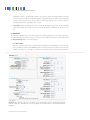
Features
•
Source inputs (write-blocked) – eSATA (SATA), PATA, USB 2.0, PCIe x 1 expansion port,
and gigabit network (NFS, iSCSI, SMB)
•
estination outputs – Dual eSATA (SATA) ports to store acquired data on one or two
D
disks, SD card, or gigabit network (iSCSI, NFS, SMB)
•
ata acquisition modes – physical image DD, physical image E01 with empty block
D
compression, logical image L01, clone, and simultaneous clone & image.
•
Hash types - MD5, SHA-1, MD5 + SHA-1
•
Remote usage – Perform operations using the web browser interface from any remote
networked location in the world
•
System configuration management via front panel LCD or web browser interface
•
User profiles can be password protected and assigned specific permission levels
•
ata log captures a complete history of data acquisitions and can be managed and
D
printed from web browser or extracted to a user-specific document
•
Stealth Mode available for use with night vision goggles (not included)
Wiebetech Branding
ABCDEFGHIJKLMNOPQRSTUVWXYZ
abcdefghijklmnopqrstuvwxyz
Product Name:
Univers 73 Black Extended
2c85m76y
PMS 711C
66c7m7y
PMS 299C
2
Ditto Forensic FieldStation User Manual
TABLE OF CONTENTS
1 PRE-INSTALLATION STEPS
1 Pre-Installation Steps
2
2 Setup
3
3 Browser Interface
3
3.1 Accessing the Browser Interface
3
3.2 Icons Used in the Browser Interface
5
3.3 User Accounts
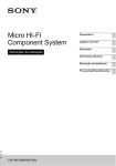
1.1 PACKAGE CONTENTS
The following list contains the items that are included in the
complete configuration for this device. Please contact CRU if
any items are missing or damaged:
6
Ditto Forensic FieldStation Unit
1
4 Home Screen
6
Unitized SAS-to-eSATA + Mini-Fit power cable
3
4.1 Action
6
IDE cable
1
4.1.1 Clone Source Disk
7
12V power supply
1
4.1.2 Physical Image Source Disk
7
Power cord
1
4.1.3 Logical Image Source Disk
8
Legacy power-to-Mini-Fit cable
1
4.1.4 Clone and Image Source Disk
10
Ethernet cable (RJ45)
1
4.1.5 Erase Destination Disk
11
2.5” IDE-to-3.5” IDE and Mini-Fit cable
1
4.1.6 Hash Disk
12
Power adapter, legacy-to-SATA
1
4.1.7 Snapshot Disk
12
4.1.8 NetView Scan
12
Velcro cable wrap
6
eSATA cable
2
SD card (pre-installed)
1
Quick Start Guide
1
4.2 Investigation Info
13
4.3 System Settings
13
4.4 Current Status
13
4.5 Disks
14
4.6 System Log
15
5 Configure Screen
16
6 Admin Screen
27
6.1 User Accounts
27
6.2 Permission Levels
27
6.3 Adding a New User
28
6.4 Editing an Existing User
28
6.5 Deleting a User
28
7 Logs Screen
28
8 Utilities Screen
29
9 Using the Front Panel Interface in Standalone Mode
31
10 Stealth Mode
35
11 Advanced Features and Functions
36
11.1 Netview Scan
36
11.2 Target Mode: Remotely Access Disks Attached to the
Ditto Forensic FieldStation with Third Party Software
38
11.3 Using iSCSI Devices
39
11.4 Using NFS and SMB (Samba) Shares
42
11.5 Adding a New Logical Image Mode
42
12 Upgrading Firmware
43
13 Technical Specifications
45
Protecting Your Digital Assets
TM
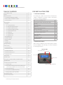
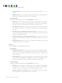
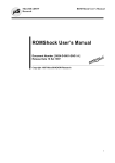
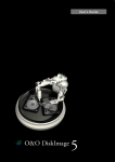
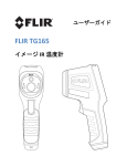
1.2 IDENTIFYING PARTS
Take a moment to familiarize yourself with the parts of the Ditto
Forensic FieldStation. This will help you to better understand
the following instructions.
TOP OF UNIT
Power Available LEDs
LCD Menu
Source LEDs
Destination LEDs
Navigation Buttons for LCD Menu
3
Ditto Forensic FieldStation User Manual
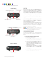
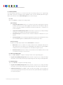
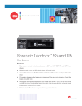
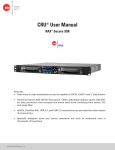
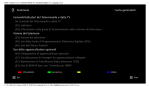
SOURCE INPUTS
(all inputs are write-blocked)
RJ45 Gigabit Ethernet Connection
4-pin Mini-Fit Power Connection
(DC Power Output)
2 SETUP
Plug the “suspect” disks or devices into the Source Inputs side of
the Ditto Forensic FieldStation. All source inputs are write-blocked
to prevent alteration. The source inputs include a USB 2.0 connec-
IDE/PATA Connection
tion for USB devices, an RJ45 gigabit Ethernet connection, an IDE/
PATA disk connection, and an eSATA connection for SATA disks or
an eSATA device. The expansion module connection is used with
the SAS, USB 3.0, and other Ditto Forensic FieldStation expansion
modules.
Expansion Module Connection
USB 2.0 Type A Connection
eSATA Connection
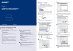
Use the Destination Outputs side of the Ditto Forensic FieldStation to store acquired data. The destination output connections
include two eSATA connections for SATA disks or eSATA devices
and an RJ45 gigabit Ethernet connection.
The rear of the Ditto Forensic FieldStation has an SD card slot and
two powering options: a 12V input for the power supply, and a
SATA power connection. The rear also has a hook for hanging the
unit inside the computer case or workstation.
DESTINATION OUTPUTS
eSATA Connections
RJ45 Gigabit Ethernet Connection
NOTE
CRU recommends that you switch the power off to
the Ditto when you add or remove a device from it in
order to avoid disk damage and data corruption.
3 BROWSER INTERFACE
The Ditto Forensic FieldStation can be configured and operated
either from the Front Panel (see Section 9) or through a web
browser.
Stealth Mode Switch
4-pin Mini-Fit Power Connections
(DC Power Output)
3.1 ACCESSING THE BROWSER INTERFACE
3.1.1 Accessing Via A Network
a. Plug an Ethernet cable into the Ethernet port on the
“Source Inputs” side of the Ditto Forensic FieldStation.
b. Connect the other end of the Ethernet cable to your
network. This usually means plugging it into a router or
REAR OF THE UNIT
Power Switch
(0 = off, 1 = on)
Hanging Hook
hub. In an office environment, you may have a network
jack built into your office wall.
c. Connect the power cable to the rear of the Ditto
Forensic FieldStation and to the provided AC adapter
or to SATA power.
d. Turn on the Ditto Forensic FieldStation’s power using
Power Input for AC Supply
SD Card Slot
SATA Power Connection
Protecting Your Digital Assets
TM
the switch on the rear panel. (0 = off, 1 = on)
4
Ditto Forensic FieldStation User Manual
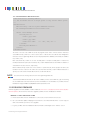
e. Type the Ditto Forensic FieldStation’s source IP address into your web browser. If you know the
address, go down to the last step of this section. If you do not know the address, continue to the next
step.
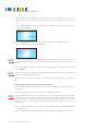
f. Press the Down navigation button on the Ditto Forensic FieldStation until you reach the “Settings”
menu. Then press Enter.
Settings
View/Edit >
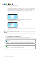
g. Press the Up or Down navigation buttons until you reach the “Source IP Address” screen.
h. Type the IP address shown into your web browser.
Source IP Address:
10.xxx.xxx.xxx
NOTE
The Ditto Forensic FieldStation is configured by default to use DHCP for IP assignment. If you need
to change to a static IP address, check with your network administrator and see Section 3.3.2 of this
manual.
i. Log into the browser interface (the default user name and password for the administrator account are
both “admin”).
NOTE
CRU recommends that you change the admin account password and create user accounts for individual
users as best data management practices.
You are now ready to use the browser interface to configure settings and preview, image, or clone attached
disks.
3.1.2 Accessing Via Direct Connection to Your Computer
a. Plug an Ethernet cable into the Ethernet port on the “Destination Outputs” side of the Ditto Forensic
FieldStation.
b. Connect the other end of the Ethernet cable to your computer’s Ethernet port.
STOP!
The destination Ethernet port can be configured to act as a server. Attaching a Ditto Forensic FieldStation acting as a server to an existing network through the destination Ethernet port will cause network
conflicts. Therefore it is important to attach the Ditto Forensic FieldStation directly to your computer
instead. To change this setting so that the Ditto Forensic FieldStation no longer acts as a server, see
Section 5.2.3.
c. Connect the power cable to the rear of the Ditto Forensic FieldStation and to the provided AC adapter
or to SATA power.
d. Turn on the Ditto Forensic FieldStation’s power using the switch on the rear panel. (0 = off, 1 = on)
Protecting Your Digital Assets
TM
5
Ditto Forensic FieldStation User Manual
e. Type the Ditto Forensic FieldStation’s destination IP address into your web browser. The default IP
address for the destination Ethernet port is 10.10.10.1. If you have changed the address and do not
remember it, continue to the next step. Otherwise, go down to the last step of this section.
f. Press the Down navigation button on the Ditto Forensic FieldStation until you reach the “Settings”
menu. Then press Enter.
Settings
View/Edit >
g. Press the Up or Down navigation buttons until you reach the “Dest. IP Address” screen.
h. Type the IP address shown into your web browser.
Dest. IP Address:
10.xxx.xxx.xxx
i. Log into the browser interface (the default user name and password for the administrator account are
both “admin”).
NOTE
CRU recommends that you change the admin account password and create user accounts for individual
users as best data management practices.
You are now ready to use the browser interface to configure settings and preview, image, or clone attached
disks.
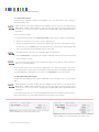
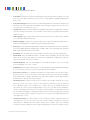
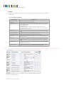
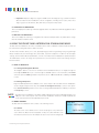
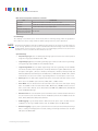
3.2 ICONS USED IN THE BROWSER INTERFACE
The browser interface uses several icons that may be clicked on to perform certain actions.
ICON
ACTION
Information
Opens a window with a brief description of the setting the information icon appears next
to.
Refresh
Refreshes the field that the icon appears next to in order to give updated information.
Reset
Loads the defaults for the setting that the Refresh icon appears next to.
Add
Adds a user defined field to a list of items.
Remove
Removes a user defined field from a list of items.
Protecting Your Digital Assets
TM
6
Ditto Forensic FieldStation User Manual
3.3 USER ACCOUNTS
The Ditto Forensic FieldStation employs a user account system to control access to its features. The “Login”
screen presents you with the ability to log in through http, or you can click the Secure Login (HTTPS) link to
log in securely. Accept the certificate and/or continue to the website, even if your browser tells you it does
not recognize it.
The default user name and password for the Administrator account are both “admin”. CRU recommends that
you change the admin account password and create user accounts for individual users as best data management practices.
Click on the Log Out button at the top right of the browser interface to log out.
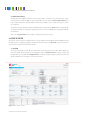
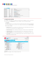
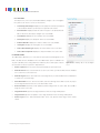
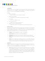
4 HOME SCREEN
The “Home” screen is where you will perform most of your operations with the Ditto Forensic FieldStation, and is
the default screen to load upon logging into the browser interface. Click on the Home tab to access the “Home”
sceen from any other area of the browser interface.
4.1 ACTION
The “Action” panel lets you start, abort, and document the following actions. The “Start” button begins the
action. The “Abort” button stops the action in progress. Click the Comment button to write a note that will
be appended to the log. Click the Configure button to modify the default settings for each action, which can
also be modified on the “Configure” screen (See Section 5).
Figure 1. The “Home” screen.
Protecting Your Digital Assets
TM
7
Ditto Forensic FieldStation User Manual
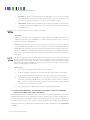
4.1.1 Clone Source Disk
The Ditto Forensic FieldStation makes an exact duplicate of the source disk and can clone to a single or
mirrored destination disk.
NOTE
While cloning the source disk, the Ditto Forensic FieldStation can also hash the source disk using the
MD5, SHA-1, or MD5 + SHA-1 algorithms. Select the hash type under the “System Settings” panel
on the “Home” screen. See Section 4.3. Hashing while using both MD5 + SHA-1 significantly reduces
performance.
To clone, follow these steps:
a. Using the browser interface, select Clone Source Disk from the “Action to Perform” drop-down box.
b. Select the source disk to clone from the “Source” drop-down box.
c. Select the destination disk from the “Destination” drop-down box. To clone to two destination disks at
the same time, select the Mirror option. Destination disks do not have to be the same physical media
as the source disk, but each must be larger than the source disk.
NOTE
For the Mirror feature to be shown, two destination disks must be attached.
d. Click the Start button. A “Completed” message box will pop up when the action has finished. Click
on the message to continue.
NOTE
You can increase the performance of the operation by clicking off of the browser interface window so
that it is not continually updated.
You can view the results of the clone action by scrolling down to the “System Log” panel on the “Home”
screen. Find and click on the latest link, which will be denoted by a filename with a date/timestamp format:
“S_yyyymmddhhmmss”. Alternatively, you can click on the Logs button from the top menu bar.
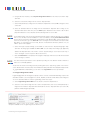
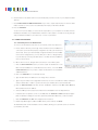
4.1.2 Physical Image Source Disk
The Ditto Forensic FieldStation creates an E01 or DD image of the source disk on one or two destination
disks.
NOTE
While imaging the source disk, the Ditto Forensic FieldStation can also hash the source disk using the
MD5, SHA-1, or MD5 + SHA-1 algorithms. Select the hash type under the “System Settings” panel
on the “Home” screen. See Section 4.3. Hashing while using both MD5 + SHA-1 significantly reduces
performance.
For the fastest performance, we recommend utilizing an NTFS file system for Windows, HFS+ for Mac, or
XFS for Linux machines. To create a physical image, follow the steps on the next page:
Figure 2. The “Action” section on the “Home” screen, showing the
options available for the “Clone Source Disk” action.
Figure 3. The “Action” section on the “Home” screen, showing the
options available for the “Physical Image Source Disk” action.
Protecting Your Digital Assets
TM
8
Ditto Forensic FieldStation User Manual
a. Using the browser interface, select Physical Image Source Disk from the “Action to Perform” dropdown box.
b. Select the source disk to image from the “Source” drop-down box.
c. Select which partition(s) to image from the “Partition” drop-down box. Choose All to image the entire
source disk.
d. Select the destination disk for the image from the “Destination” drop-down box. To image to two
destination disks at the same time, select the Mirror option. Destinations do not have to be the same
physical media as the source disk, but each must be larger than the source disk.
NOTE
For the Mirror feature to be shown, both destination disks must be empty. A quick way to accomplish
this is to use the Ditto Forensic FieldStation to erase each disk by selecting Erase Destination Disk
from the “Action to Perform” drop-down box and using the “Clear Partition Table” erase mode (see Section 4.1.5). You must also go to the Erase tab on the “Configure” Screen and make sure that “Format
After Erase” is unchecked (see Section 5.6), because if a destination disk has a partition on it, the
“Mirror” option will not appear.
e. Select which type of physical image you would like to create from the “Physical Image Type” dropdown box. The image types available are E01 or DD. You can modify which image type appears by
default in the drop-down box on the “Home” screen’s “System Settings” section (see Section 4.3), or
on the “Configure” screen’s “System” tab (see Section 5.1).
f. Click the Start button. A “Completed” message box will pop up when the action has finished. Click
on the message to continue.
NOTE
You can increase the performance of the operation by clicking off of the browser interface window so
that it is not continually updated.
You can view the results of the image action by scrolling down to the “System Log” panel on the “Home”
screen. Find and click on the latest link, which will be denoted by a filename with a date/timestamp format:
“S_yyyymmddhhmmss”. Alternatively, you can click on the Logs button from the top menu bar.
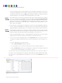
4.1.3 Logical Image Source Disk
Logical imaging allows an investigator to quickly scan the contents of a hard disk and image only the files
and folders relevant to the investigation into an L01, ZIP, TAR, or LIST file format. Data can be imaged to
one or two destination disks. To create a logical image, follow these steps:
a. Select Logical Image Source Disk from the “Action to Perform” drop-down box.
b. Select the source disk to image from the “Source” drop-down box, then choose which partition(s) to
image from the “Partition” drop-down box underneath the “Source” drop-down box. If you select “All”,
partitions will be imaged sequentially.
Figure 4. The “Action” section on the “Home” screen, showing
the options available for the “Logical Image Source Disk” action.
Protecting Your Digital Assets
TM
9
Ditto Forensic FieldStation User Manual
c. Select the destination disk for the logical image from the “Destination” drop-down box, then choose
the destination disk partition from the “Partition” drop-down box underneath. To image to two destination disks at the same time, select the Mirror option. Destination disks do not have to be the same
physical media as the source disk, but each must be larger than the source disk.
NOTE
For the Mirror feature to be shown, both destination disks must be empty. A quick way to accomplish
this is to use the Ditto Forensic FieldStation to erase each disk by selecting Erase Destination Disk
from the “Action to Perform” drop-down box and using the “Clear Partition Table” erase mode (see Section 4.1.5). You must also go to the Erase tab on the “Configure” Screen and make sure that “Format
After Erase” is unchecked (see Section 5.6), because if a destination disk has a partition on it, the
“Mirror” option will not appear.
d. Select which type of logical image you would like to create from the “Logical Image Type” drop-down
box. The format options available are L01, TAR, ZIP, or LIST. (You can modify which logical image type
appears by default in the drop-down box on the “Configure” screen’s “System” tab. See Section 5.1.)
NOTE
“Logical Image Source Disk” actions create a report of directories and files chosen from the source disk
as well as their file sizes and any error messages encountered. This report can be viewed from within
the browser interface and can be exported as an Excel spreadsheet. See Section 7.1.4.
e. Select the Logical Image Mode from the “Logical Image Mode” drop-down box. See the list of logical
image modes at the end of this subsection for information on what each mode does.
f. If you chose any other Logical Image Mode, click the Start button at the top of Action section. A
“Completed” message box will pop up when the action has finished. Click on the message to continue.
If you chose “Manual Select”, follow these steps:
i. Click on Select Files & Dirs. A dialog box will open.
ii. Use the navigation tree to select the files and folders you wish to image (See Figure 5).
iii. Click the Start button at the bottom of the dialog box. A “Completed” message box will pop up
when the action has finished. Click on the message to continue.
You can view the results of the logical image action by scrolling down to the “System Log” panel on
the “Home” screen. Find and click on the latest link, which will be denoted by a filename with a date/
timestamp format: “S_yyyymmddhhmmss”. Alternatively, you can click on the Logs button from the top
menu bar.
Figure 5. The file navigation tree.
Protecting Your Digital Assets
TM
10
Ditto Forensic FieldStation User Manual
Logical Image Modes
Beginning with the September 19, 2015 firmware update, the Logical Image action can automatically
search for files that fit the following Logical Image Modes. The action will search for specific file extensions specified by the Logical Image Mode. See the next page for information on specific file types.
Logical Image Modes, continued...
•
Manual Select: Enables the “Select Files & Dirs” button so that you can manually select which
files to logically image.
•
All Files and Dirs: Images all files and directories.
•
All Except Windows: Images all files and directories except for the Windows directory.
•
All Except Windows and Programs: Images all files and directories except for the Windows,
Program Files, Program Files (x86), and ProgramData directories.
•
All Users - Windows: Images the Windows “Users” directory.
•
All Temporary - Windows: Images the Windows/Temp and Temp directories.
•
All Except Swap and Hibernate: Images all files and directories except files named hiberfil.sys,
pagefile.sys, Win386.swp, and 386part.par.
•
All Media Files: Images all .avi, .jpeg, .jpg, .wav, and .mov files, as well as all files with extensions beginning in “.mp” (.mpeg, .mp4, .mp3, etc.) and all files with extensions beginning in “.m4”
(.m4a, .m4v, etc.).
•
All Office Files: Images all .txt and .pdf files, as well as all files with extensions beginning in “.doc”,
“.xls”, “.ppt”(.doc, .docx, .xlsx, .pptx, etc.).
•
All Financial Files: Images all .ifx, .ofx, .qfx, .qif, and .tax files.
You may also add your own customized logical image modes to this drop-down list. To do so, see Section 11.5.
4.1.4 Clone and Image Source Disk
This action simultaneously creates a clone of the source disk on one destination disk and creates an image
on a second destination disk. Two destination disks are required for this action.
NOTE
While cloning and imaging the source disk, the Ditto Forensic FieldStation can also hash the source disk
using the MD5, SHA-1, or MD5 + SHA-1 algorithms. Select the hash type under the “System Settings”
panel on the “Home” screen. See Section 4.3. Hashing while using both MD5 + SHA-1 significantly
reduces performance.
To simultaneously create a clone and a physical image of the source disk, follow these steps:
a. Select Clone & Image Source Disk from the “Action to Perform” drop-down box.
b. Select the source disk to clone and image from the “Source” drop-down box.
c. Select the destination disk for the clone from the “Clone Destination” drop-down box and the destination disk for the image from the “Image Destination” drop-down box. Destination disks do not have to
be the same physical media as the source disk, but each must be larger than the source disk.
Protecting Your Digital Assets
TM
11
Ditto Forensic FieldStation User Manual
d. Select the destination disk partition on which to save the image file from the “Image Partition” dropdown box.
e. Select which type of physical image you would like to create from the “Physical Image Type” dropdown box. The image types available are E01 or DD. (You can modify which image type appears by
default in the drop-down box on the “Configure” screen’s “System” tab. See Section 5.1.)
f. Click the Start button. A “Completed” message box will pop up when the action has finished. Click
on the message to continue.
You can view the results of the clone and image action by scrolling down to the “System Log” panel on
the “Home” screen. Find and click on the latest links, which will be denoted by a filename with a date/
timestamp format: “S_yyyymmddhhmmss”. Alternatively, you can click on the Logs button from the top
menu bar.
4.1.5 Erase Destination Disk
The Ditto Forensic FieldStation erases the destination disk using your preferred Erase Mode. The Erase
Modes available are Clear Partition Table, Quick Erase, LBA/Offset Pattern, Custom Erase, Secure Erase
Normal, Secure Erase Enhanced, DOD Clear, DOD Sanitize, NIST800-88 Clear, and NIST800-88 Purge.
To erase a disk, follow these steps:
a. Select Erase Destination Disk from the “Action to Perform” drop-down box.
b. Select the Erase Mode to use from the “Erase Mode” drop-down box. (You can modify which erase
mode appears by default in the drop-down box on the “Configure” screen’s “System” tab. See Section 5.1.)
c. Select the target destination disk(s) from the “Target” drop-down box.
d. Click the Start button. A “Completed” message box will pop up when the action has finished. Click
on the message to continue.
You can view the results of the erasure action by scrolling down to the “System Log” panel on the “Home”
screen. Find and click on the latest link, which will be denoted by a filename with a date/timestamp format:
“S_yyyymmddhhmmss”. Alternatively, you can click on the Logs button from the top menu bar.
Format After Erase
You can configure the Ditto Forensic FieldStation to automatically format a disk after you erase it. Click
on the Configure tab to go to the “Configure” screen. Then click on the Erase tab make sure that
“Format After Erase” is checked for each of the erase modes on which you’d like to enable this setting.
Figure 6. The “Action” section on the “Home” screen, showing
the options available for the “Clone & Image Source Disk” action.
Protecting Your Digital Assets
TM
Figure 7. The “Action” section on the “Home” screen, showing the
options available for the “Erase Destination Disk” action.
12
Ditto Forensic FieldStation User Manual
4.1.6 Hash Disk
The Ditto Forensic FieldStation will hash any source or a destination disk using your preferred algorithm.
Hash values are saved in the System Log. The available algorithms are “MD5”, “SHA-1”, or “MD5 + SHA-1”.
To hash a disk, follow these steps:
a. Select Hash Disk from the “Action to Perform” drop-down box.
b. Select your preferred hash algorithm from the “Hash Type” drop-down box. (You can modify which
hash algorithm appears by default in the drop-down box on the “Configure” screen’s “System” tab.
See Section 5.1.)
c. Select the target disk from the “Target” drop-down box.
d. Select the partition you want to hash from the “Partition” drop-down box.
e. Click the Start button. A “Completed” message box will pop up when the action has finished. Click
on the message to continue.
You can view the results of the hash action by scrolling down to the “System Log” panel on the “Home”
screen. Find and click on the latest link, which will be denoted by a filename with a date/timestamp format:
“S_yyyymmddhhmmss”. Alternatively, you can click on the Logs button from the top menu bar.
4.1.7 Snapshot Disk
The Ditto Forensic FieldStation provides S.M.A.R.T. and hdparm information for any source or destination
disk connected to itself. No clone or image request needs to be done.
To create a snapshot of a disk, follow these steps:
a. Select Snapshot Disk from the “Action to Perform” drop-down box.
b. Select the target disk from the “Target” drop-down box.
c. Click the Start button. A “Completed” message box will pop up when the action has finished. Click
on the message to continue.
You can view the results of the snapshot action by scrolling down to the “System Log” panel on the
“Home” screen. Find and click on the latest link, which will be denoted by a filename with a date/timestamp format: “S_yyyymmddhhmmss”. Alternatively, you can click on the Logs button from the top menu
bar.
Scroll to “eSATA Extended Disk Info” to see recorded data, including S.M.A.R.T. and hdparm information.
4.1.8 NetView Scan
NetView is a network tool that can be used to discover machines on a network and even probe them for
specific services that they may be running. This capability can help an investigator locate physically hidden
Figure 8. The “Action” section on the “Home” screen, showing
the options available for the “Hash Disk” action.
Protecting Your Digital Assets
TM
Figure 9. The “Action” section on the “Home” screen, showing
the options available for the “Snapshot Disk” action.
13
Ditto Forensic FieldStation User Manual
computers or quickly determine whether a machine is acting as a data storage device
that the Ditto Forensic FieldStation can image.
See Section 11.1 for more information about the NetView Scan feature.
4.2 INVESTIGATION INFO
The Investigation Info panel groups related information that may also be used in creating
custom directories and file names (see Section 5.8). The “Hide” button allows you to
minimize the panel.
Click the Edit button to enter information about the Investigator, Case Number, Evidence Number, Description, Notes, Base directory prefix, and a Base filename prefix for
Figure 10. The “Action” section on the “Home” screen,
showing the options available for the “Netview Scan”
action.
an E01 or DD image.
Each field is filtered to block non-printable ASCII characters. Any characters at the file
system level that may not be safe for a directory name or file name will be filtered out
and replaced with an underscore. Only printable ASCII characters are currently allowed
for directory and filenames. Multiple underscores will also be reduced to a single underscore per naming item.
The Ditto Forensic FieldStation will generate an error message if you enter a non-printable ASCII character or if your message exceeds the 58 character limit. Additionally,
Figure 11. The “Investigation Info” section.
when the final directory or filename that uses any of these fields is created, another level
of filtering is applied.
STOP!
Using apostrophes (‘) in the name fields will cause an error when the file or folder
name is created. They should not be used in the Investigation Info fields.
4.2.1 User Defined Fields
Click on the green plus sign icon to open the “Add User Defined Field” window (see
Figure 12). You may add as many user defined fields as you wish. Each user defined
Figure 12. The “Add User Defined Field” window.
field must have a title, XML tag, and value.
The title identifies the value in the Ditto Forensic FieldStation’s browser and LCD
interfaces, and the XML tag only appears in the configuration and log files.
To remove a user defined field, click on the green minus sign icon.
4.3 SYSTEM SETTINGS
Displays the current configuration settings of the Ditto Forensic FieldStation. These set-
Figure 13. The “System Settings” section.
tings are loaded as the default settings for the actions you perform in the “Action” panel.
The “Hide” button allows you to minimize the panel. Click the Edit button to customize
these settings. See Section 5.1 for details on each option.
4.4 CURRENT STATUS
Reports either as “Idle” or displays info about the action that the Ditto Forensic FieldStation is currently performing.
Protecting Your Digital Assets
TM
Figure 14. The “Current Status” section, displaying a
the status of a Physical Image action.
14
Ditto Forensic FieldStation User Manual
Figure 15. The “Disks” section on the “Home” screen.
4.5 DISKS
Displays information about the attatched disks that are currently connected to the Ditto
Forensic FieldStation.The “Hide” button allows you to minimize the panel. To see the
available space a disk has, click the green double arrow icon next in the “Used” column
header (see Figure 16). The disk usage will refresh and give an updated amount.
The “Target Mode” button allows you to present the disks attached to the Ditto Forensic
Figure 16. Clicking the green double arrow icon displays and updates amount of space currently used and
available.
FieldStation as iSCSI disks on a network. This is useful if you wish to use third party data
acquisition tools against the disks without creating an image. The “Source Network” and
“Source Destination” buttons are used for mounting iSCSI devices as well as NFS and
SMB shares to the Ditto Forensic FieldStation. For more information, see Section 11.
4.5.1 Previewing and Browsing Disks
To browse or download disk data, or to select files and folders for logical imaging,
click on a partition’s number under the disk’s “Partition” column and then select Preview (see Figure 17). This opens up a file explorer window where you can navigate
through the files and folders on the disk.
Figure 17. Drop-down menus for a disk (left) and a
disk’s partition (right).
Directory Toolbar and Right-Click Context Menu Items
ICON
ACTION
Collapse Folder Tree
Collapses the entire folder tree so that only the previewed partition’s
folder is visible.
Refresh
Refreshes the folder contents in order to give updated information.
Up
Moves up to the parent folder.
Back
Moves back to the previously viewed folder.
Folders
Toggles whether folders are displayed in the contents panel.
Select Mode
Toggles the ability to select individual files for logical imaging.
Protecting Your Digital Assets
TM
15
Ditto Forensic FieldStation User Manual
Directory Toolbar and Right-Click Context Menu Items, continued...
ICON
ACTION
Detail View/List View
Toggles whether the Size, Type, Date Created, Date Modfied, and Date
Accessed columns are visible.
Size Format
Changes whether file sizes in the “Size” column are measured as
bytes or as megabytes, gigabytes, etc.
Opens the selected file. Images and PDF files will open in a preview
window. Other files will open a dialog box to download the file to your
computer.
View
Download
Opens a dialog box to download the selected file to your computer.
Hash
Opens an info window with the selected file’s name, MD5 hash, and
file size in bytes.
HexView
Opens the file in the Ditto Forensic FieldStation’s built-in hexadecimal
viewer.
Logically Image Data
To logically image data using the “Preview” window, click on the Select Mode button and then
check the box next to each file or folder you want to logically image. When you are finished, click on
the Stage button in the lower right corner of the “Preview” window. You will be taken back to the
“Home” screen. Use the “Action” control panel as directed in Section 4.1.3. When you click on “Select
Files & Dirs”, you will be asked to confirm whether to logically image the files and folders you have
selected, or to select new files and folders.
4.5.2 View Hexidecimal Data
To view a disk’s hexidecimal data, click on the disk name under the “Port” column and then select HexView. To view a disk partition’s hexidecimal data, click on the partition’s number under the disk’s “Partition” column and then select HexView (see Figure 17).
4.5.3 View Snapshot Data
To view a disk’s snapshot information, click on the disk name under the “Port” column and then select
Snapshot.
4.6 SYSTEM LOG
Shows the actions that the Ditto Forensic FieldStation has performed (see Figure 18). The “Hide” button
allows you to minimize the panel. The “Comment” button allows you to write a note that is appended to the
log.
If there is no SD card present in the SD card slot, this panel displays the logs that have been stored in volatile memory since the Ditto Forensic FieldStation’s last power cycle. These logs are deleted when the Ditto
Forensic FieldStation is powered down. If there is an SD card present, this panel displays all actions saved on
the SD Card.
To view the log details of a particular action, click on the link under the “Message” column. which will be
denoted by a filename with a date/timestamp format: “S_yyyymmddhhmmss”. Alternatively, you can click on
the Logs button from the top menu bar.
Protecting Your Digital Assets
TM
16
Ditto Forensic FieldStation User Manual
Figure 18. The “System Logs” section on the “Home” screen.
5 CONFIGURE SCREEN
The “Configure” screen allows you to modify the way the Ditto Forensic FieldStation functions to suit your specific needs. Click on the Configure tab to access the “Configure” screen from the browser interface.
5.1 SYSTEM
The “System” tab allows you to view and customize the following settings. This information is also displayed
in the “System Settings” panel on the “Home” screen. When you are finished, click the Commit Changes
button to save the changes.
•
Default Format: This is the default file system that will be used to format destination disks when they
are used in actions that the Ditto Forensic FieldStation performs.
•
Physical Image Type: Sets the default physical image type for all actions that create a physical image.
•
Logical Image Type: Sets the default logical image type for the “Logical Image Source Disk” action.
•
Logical Image Mode: Sets the default Logical Image Mode for the “Logical Image Source Disk” action.
•
Verify Single: Determines whether individual destination disk are hashed and compared to the hash
value of the source disk’s hash value.
Figure 18. The “Configure” screen, showing the “System” tab.
Protecting Your Digital Assets
TM
17
Ditto Forensic FieldStation User Manual
•
Verify Mirror: Determines whether mirrored destination disks are hashed and compared to the hash
value of the source disk’s hash value(s). You can choose to verify eSATA-A or eSATA-B individually, both
disks, or none.
•
Verify Clone & Image: Determines whether cloned and imaged disks are hashed and compared to the
hash value of the source disk’s hash value during a “Clone & Image Source Disk” action. You can choose
to verify the clone, the image, both, or none.
•
Log Disk Info: Determines whether S.M.A.R.T. and hdparm disk information is logged before running an
action, after running an action, both, or not at all. CRU recommends that you log disk information before
and after an action.
•
HTML Logging: Logs are always saved in .XML format. This option causes the Ditto Forensic FieldStation to save logs in HTML format as well.
•
DiskView Logging: Logs any action to preview a disk or actions performed while previewing a disk (i.e.
starting or finishing a preview of a disk, starting or finishing a HexView action).
•
Hash Type: Sets the default hash algorithm that will be used for disk verification and the “Hash Disk”
action. The available algorithms are MD5, SHA-1, or MD5 + SHA-1. Note that hashing while using both
MD5 + SHA-1 significantly reduces performance.
•
Erase Mode: Sets the default erase mode that will be used for all actions that require erasing disks.
•
Stealth Mode: Turns off all LEDs and LCDs on the Ditto Forensic FieldStation. The physical “Stealth
Mode” Switch serves the same purpose (see Section 1.2). If Stealth Mode is enabled from the browser
interface, the physical switch cannot override it.
•
LCD/LED Brightness: Sets the relative brightness of the LCDs and LEDs on the face of the Ditto
Forensic FieldStation on a scale of 1 to 255.
•
Audible Buzzer: This is a planned feature that is not currently implemented. The audible buzzer will alert
the user to various actions that occur when using the Ditto Forensic FieldStation.
•
Prompt Invest. Info: Opens a “Configure Investigation Info” window after the user has hit the “Start”
button in the “Action” section on the “Home” screen. This allows the user to customize the Investigator,
Case Number, Evidence Number, Description, Notes, Base Directory Name, and the Base File Name
information prior to performing the requested action.
•
LCD Prompt Case: Five options may be chosen to modify the case number specified in the “Investigation Info” section of the “Home” screen. The case number is included in the log for the requested
action. “Disabled” leaves the case number as it is. “Inc/Dec” allows you to manually increment the
case number up or down using the navigation buttons on the face of the Ditto Forensic FieldStation.
“AutoInc” automatically increments the case number, and “AutoInc/Pause” automatically increments
the case number, but displays a confirmation prompt the LCD screen before beginning the requested
action. These options require a number to be present on the end of the Case Number specified in the
“Investigation Info” section.
•
LCD Prompt Evidence: Five options may be chosen to modify the evidence number specified in the
“Investigation Info” section of the “Home” screen. The evidence number is included in the log for the
requested action. “Disabled” leaves the evidence number as it is. “Inc/Dec” allows you to manually
increment the evidence number up or down using the navigation buttons on the face of the Ditto Forensic
Protecting Your Digital Assets
TM
18
Ditto Forensic FieldStation User Manual
FieldStation. “AutoInc” automatically increments the evidence number, and “AutoInc/Pause” automatically increments the evidence number, but displays a confirmation prompt the LCD screen before beginning the requested action. These options require a number to be present on the end of the Evidence
Number specified in the “Investigation Info” section.
•
Quick Start: Enables the “Quick Start” screen on the LCD that appears after you boot or reboot the Ditto
Forensic FieldStation. The settings for this mode may be modified in the “Quick Start” tab. See Section
5.9.
5.2 NETWORK
The “Network” tab allows you to view and customize the following settings. If you are unsure or have questions about changing your network settings, contact your network administrator. When you are finished, click
the Commit Changes button to save the changes.
5.2.1 Host Name
Allows you to change what name for the Ditto Forensic FieldStation will be displayed on a network. Host
names are not case sensitive, but must begin with any letter “A-Z”. They can contain the the letters A-Z,
numbers 0-9, underscore “_”, and dash “-” characters. Host names must also be limited to 64 characters.
Figure 20. The “Network” tab on the “Configure” screen, showing the “Source”, “Destination”, and “Wifi”
network settings. The “Wifi Network” section only appears when a USB wireless network adapter has been
plugged in.
Protecting Your Digital Assets
TM
19
Ditto Forensic FieldStation User Manual
5.2.2 Source Network
The “Source Network” section displays the source Ethernet port’s MAC Address as well as its IP assignment method. You can choose either “DHCP (Auto Config)” or “Static IP (Manual Settings)” from the top
drop-down box.
The “Remote Accessibility” drop-down box allows you to choose whether or not the Ditto Forensic FieldStation responds to any network traffic via the source Ethernet port.
5.2.3 Destination Network
The “Destination Network” section displays the source Ethernet port’s MAC Address as well as its networking mode. You can choose either “Server”, “Client (DHCP)”, or “Client (Static IP)” from the drop-down
box.
Server
“Server” allows you to configure the Ditto Forensic FieldStation for use as a server. This can be helpful
if you are connecting an iSCSI device to the destination Ethernet port, for example (see Section 11.3.2),
or you are connecting Ditto directly to your computer instead of through your office network. The
default settings below will work for most environments. This is an advanced option, so do not customize the default server configuration below unless directed to do so by your network administrator.
IP Address: 10.10.10.1
Subnet Mask: 255.255.255.0
DHCP Server: Enabled
DHCP Start Address: 10.10.10.100
DHCP End Address: 10.10.10.199
DNS Server: Enabled
DNS Domain Name: ditto.local
NTP Server: Enabled
NAT Gateway: Disabled
STOP!
Do not connect the Ditto Forensic FieldStation to another network while it is configured as a server.
Doing so will cause network conflicts and may disrupt network traffic.
Client (DHCP)
This option automatically configures the destination Ethernet port to connect to the attached network.
Client (Static IP)
This option allows you to manually configure the destination Ethernet port to connect to the attached
network.
5.2.4 Wifi Network
The “Wifi Network” section allows you to configure a third party USB wifi network adapter that’s been
plugged into the “Souce Inputs” USB port. It also displays that port’s MAC Address. Adapters with an
Atheros chipset and some adapters with Realtek chipsets are compatible.
NOTE
The Ditto Forensic FieldStation can handle multiple USB devices through a USB hub attached to the
USB port on the “Source Inputs” side of the Forensic FieldStation.
Protecting Your Digital Assets
TM
20
Ditto Forensic FieldStation User Manual
“Wifi Mode” allows you to determine whether the Ditto Forensic FieldStation connects to a wifi network
or acts as a wifi hot spot itself. Hot Spot Mode is helpful if you are working in a separate location from
the Ditto Forensic FieldStation that is still within range of a wireless network, or if there is no hardwired
network available in the location.
Choose “Client Mode” to connect to an existing wifi network or “Hot Spot Mode” to make the Ditto
Forensic FieldStation into a wifi hot spot.
Client Mode
Check “Status: Auto Start” if you want the Ditto Forensic FieldStation to connect to the specified wireless network automatically.
To select the client mode’s networking mode, you can choose either “Client (DHCP)” or “Client (Static
IP) from the drop-down box underneath the MAC Address. “Client (DHCP)” automatically configures
the USB wifi network adapter to connect to a wifi network. “Client (Static IP)” allows you to manually
configure the connection.
Hot Spot Mode
Check “Status: Auto Start” if you want the Ditto Forensic FieldStation to begin broadcasting as a hot
spot automatically whenever a wifi adapter is plugged in.
The default settings below will work for most environments, with several exceptions.
STOP!
Input your own key to ensure that your Ditto Forensic FieldStation remains secure.
STOP!
You may be required to conform to your country’s laws and regulations regarding wireless radio frequency usage. Select your two-digit country code from the “Regulatory Domain” drop down list, and
the Ditto Forensic FieldStation will limit the frequencies it may broadcast on to only those in the permitted range(s).
STOP!
Do not connect the Ditto Forensic FieldStation to a wired network while it is configured as a hot spot.
Doing so will cause network conflicts and may disrupt network traffic.
SSID: {Host Name}-wifi
Regulatory Domain: Global
Band: G - 2.4 GHz
Channel: Auto
Broadcast: Checked
Security: WPA2 Personal
Key: ditto123
Show Key: Unchecked
IP Address: 10.10.10.1
Subnet Mask: 255.255.255.0
DHCP Server: Enabled
DHCP Start Address: 10.10.20.100
DHCP End Address: 10.10.20.199
More settings are available on the next page.
Protecting Your Digital Assets
TM
21
Ditto Forensic FieldStation User Manual
Hot Spot Mode, continued...
DNS Server: Enabled
DNS Domain Name: dittowifi.local
NTP Server: Enabled
NAT Gateway: Disabled
5.3 CLONE
The “Clone” tab allows you to view and customize the following settings for disk cloning actions, including
the “Clone & Image Source Disk” action. When you are finished, click the Commit Changes button to save
the changes.
5.3.1 Typical Settings
•
Source HPA/DCO: Sets whether the cloning action should indicate in the log that there is an HPA
(host protected area) or DCO (device configuration overlay) present, temporarily bypass the HPA,
permanently unhide the HPA, or permanently unhide both the HPA and DCO.
•
Fill to End of Disk: Check this box to enable zeroes to be written to the end of the disk.
•
Reset HPA After Fill: Sets the HPA on the destination disk so that the capacity of the destination
disk is identical to the capacity on the source disk.
5.3.2 Advanced Settings
The advanced settings may be hidden. Click the Show button to reveal them.
•
Buffer Size: Sets the the buffer size used by the Ditto Forensic FieldStation during a cloning action.
The minimum size is 512K (kilobytes). The default size of 1M (megabyte) works best for most uses.
The maximum size is limited by the target file system.
•
Exit when a bad sector is encountered: Aborts the cloning action if the Ditto Forensic FieldStation
encounters a bad sector on the source disk.
5.4 PHYSICAL IMAGE
The “Physical Image” tab allows you to view and customize the following settings for physical imaging actions,
including the “Clone & Image Source Disk” action. There are separate options available for both the “E01” and
“DD” image types. When you are finished, click the Commit Changes button to save the changes.
5.4.1 E01
Click on the E01 tab to reveal the E01 image settings.
Typical Settings
•
Image File Segment Size: Allows you to specify the size in bytes that image file segments
should be. The minimum size is 1M (megabyte). The maximum size is limited by the target file
system. If this field is left blank, the maximum size will be used. Click the “I” information icon
for more information.
•
Source HPA/DCO: Sets whether the physical image action should indicate in the log that there
is an HPA (host protected area) or DCO (device configuration overlay) present, temporarily
bypass the HPA, permanently unhide the HPA, or permanently unhide both the HPA and DCO.
Protecting Your Digital Assets
TM
22
Ditto Forensic FieldStation User Manual
•
Compression Type: Sets whether the action should use empty block compression or no compression.
•
EWF File Format: Choose which EnCase image file format should be used during E01 physical
images. CRU recommends using “encase6” for most acquisitions.
Advanced Settings
The advanced settings may be hidden. Click the Show button to reveal them.
•
Buffer Size: Sets the the buffer size used by the Ditto Forensic FieldStation during an E01
physical image action. The minimum size is 512K (kilobytes). The default size of 1M (megabyte)
works best for most uses. The maximum size is limited by the target file system.
•
Error Granularity: Determines how many sectors are ignored on a read error. The minimum
size is 512 bytes. The default size is the Buffer Size. The maximum size is limited by the target
file system.
•
Swap Byte Pairs of the Media Data (endian conversion): Check this box if you need to
convert from big-endian to little-endian or vice-versa, which may be necessary for disks used in
older x86 or PowerPC-based systems.
•
Wipe Sectors on Read Error (mimic EnCase-like behavior): If a read error is encountered
during an E01 physical image action, the Ditto Forensic FieldStation will write out zeroes to fill
the sector.
•
Read Error Retries: Specifies the number of tries the Ditto Forensic FieldStation will try to read
a sector before moving on to the next sector.
5.4.2 DD
Click on the DD tab to configure the DD image settings.
Typical Settings
•
Image File Segment Size: Allows you to specify the size in bytes that image file segments
should be. The minimum size is 1M (megabyte). The maximum size is limited by the target file
system. If this field is left blank, the maximum size will be used. Click the “I” information icon
for more information.
•
Source HPA/DCO: Sets whether the physical image action should indicate that there is an HPA
(host protected area) or DCO (device configuration overlay) present, temporarily bypass the
HPA, permanently unhide the HPA, or permanently unhide both the HPA and DCO.
Advanced Settings
The advanced settings may be hidden. Click the Show button to reveal them.
•
Buffer Size: Sets the the buffer size used by the Ditto Forensic FieldStation during a DD physical image action. The minimum size is 512K (kilobytes). The default size of 1M (megabyte)
works best for most uses. The maximum size is limited by the target file system.
•
Exit when a bad sector is encountered: Aborts the DD physical image action if the Ditto
Forensic FieldStation encounters a bad sector on the source disk.
Protecting Your Digital Assets
TM
23
Ditto Forensic FieldStation User Manual
5.5 LOGICAL IMAGE
The “Logical Image” tab allows you to view and customize the following settings for the “Logical Image
Source Disk” action. There are different options available for each of the L01, ZIP, TAR, and LIST file types.
When you are finished, click the Commit Changes button to save the changes.
5.5.1 L01
Click on the L01 tab to configure the L01 image settings.
Typical Settings
•
Image File Segment Size: Allows you to specify the size in bytes that image file segments
should be. The minimum size is 1M (megabyte). The maximum size is limited by the target file
system. If this field is left blank, the maximum size will be used. Click the “I” information icon
for more information.
•
Log File Access/Modify/Change Times: Check this box to log the access, modify, and change
timestamps of files and directories during an L01 logical image action.
•
Compression Type: Sets whether the action should use empty block compression or no compression.
•
Per File Hash Type: Sets the default hash algorithm that will be used for individual file verification. The available algorithms are MD5 and SHA-1. The default setting is “None”.
Advanced Settings
The advanced settings may be hidden. Click the Show button to reveal them.
•
Buffer Size: Sets the the buffer size used by the Ditto Forensic FieldStation during an L01
logical image action. The minimum size is 512K (kilobytes). The default size of 1M (megabyte)
works best for most uses. The maximum size is limited by the target file system.
•
Read Error Retries: Specifies the number of tries the Ditto Forensic FieldStation will try to read
a sector before moving on to the next sector.
5.5.2 ZIP and TAR Settings
Click on the ZIP or TAR tab to configure the settings for either of those logical image types.
•
Log File Access/Modify/Change Times: Check this box to log the access, modify, and change
timestamps of files and directories during the logical image action. This setting is format-dependent.
5.5.3 LIST Settings
Click on the LIST tab to configure the LIST image settings.
•
Log File Access/Modify/Change Times: Check this box to log the access, modify, and change
timestamps of files and directories during the logical image action. This setting is format-dependent.
•
Validate File Extensions: Uses MIME to make sure that the file headers of the files within the
newly created logical image list match their file extensions. Any questionable files are highlighted in
the Logical Image Report.
Protecting Your Digital Assets
TM
24
Ditto Forensic FieldStation User Manual
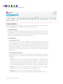
5.6 ERASE
The Ditto Forensic FieldStation allows you to view and customize settings for how the Ditto Forensic FieldStation erases disks.
5.6.1 Available Erase Modes
ERASE MODE
EXPLANATION
Clear Partition Table
Removes the partition table on the disk.
Quick Erase
Performs a single pass writing all zeroes.
LBA/Offset Pattern
Writes byte/LBA info to each sector. Each 512 byte sector is written with:
B_XXXXXXXXXXXXXX
L_DDDDDDDDDDDD
‘XXXXXXXXXXXXXX’ is the Byte offset as a hexadecimal string, and
‘DDDDDDDDDDDD’ is the LBA number as a decimal string. The remainder
of the sector is filled with zero.
Custom Erase
Performs 1-99 passes, overwriting the disk with zeroes or a user-selected
pattern.
Secure Erase Normal
Initiates the disk’s built-in Secure Erase Normal function.
Secure Erase Enhanced
Initiates the disk’s built-in Secure Erase Enhanced function.
DOD Clear
Performs the U.S. Department of Defense “Clear” standard by writing
zeroes to the drive.
DOD Sanitize
Performs the U.S. Department of Defense “Sanitize” standard by using a
0xAAAAAAA pattern, then its complement, and then another unclassified
pattern.
NIST800-88 Clear
Performs the “Clear” standard defined by NIST special publication 800-88 by
writing all zeroes to the drive.
NIST800-88 Purge
Performs the “Purge” standard defined by NIST special publication 800-88.
by initiating the drive’s built-in Secure Erase (Normal) command.
Figure 21. The “Erase” tab on the “Configure” screen, showing all available erase modes
and their customizable settings.
Protecting Your Digital Assets
TM
25
Ditto Forensic FieldStation User Manual
5.6.2 Customizable Settings
Some Erase Modes require several of the following settings to be configured a certain way as part of their
standard. In these cases, the settings cannot be modified. •
Mode Name: The name of the erase mode.
•
HPA/DCO Handling: Sets how erase actions using the specified erase mode should handle HPAs
and DCOs. It can indicate in the log that there is an HPA (host protected area) or DCO (device configuration overlay) present, temporarily bypass the HPA, permanently unhide the HPA, or permanently
unhide both the HPA and DCO.
•
Passes: For the “Custom Erase” setting only, this allows you to specify the number of passes the
disk is overwritten during the erase action. You can specify between 1 and 99 passes.
•
Overwrite Method: For the “Custom Erase” setting only, you can specify a pattern for the disk to
write repeatedly across the entire disk. If “text” is selected from the drop-down box, the “Pattern”
field must contain one or more ASCII characters. If “hex” is selected, the “Pattern” field must contain an even number of ASCII characters representing hexadecimal digits (e.g. 17a64F). Leaving the
“Pattern” field blank tells the Ditto Forensic FieldStation to use zeroes.
•
Verify: This is a planned feature that is not currently implemented. The “Verify” drop-down box will
allow you to verify the erased disk after it has been fully erased. If “Quick” is selected, the beginning,
middle, and end of the disk will be read to ensure that the last pattern was actually written. If “Full”
is selected, the entire disk will be read to ensure that the last pattern was actually written. If “None”
is selected, no verification will be performed.
•
Format After Erase: Check this box to format the disk with the default format. The default format
can be set in the “System” tab on the “Configure” screen (see Section 5.1).
5.7 HASH
The “Hash” tab allows you to view and customize the following settings for all hash actions. When you are
finished, click the Commit Changes button to save the changes.
•
Buffer Size: Sets the the buffer size used by the Ditto Forensic FieldStation during a hash action. The
minimum size is 512K (kilobytes). The default size of 1M (megabyte) works best for most uses. The
maximum size is limited by the target file system.
•
Exit when a bad sector is encountered: Aborts the hash disk action if the Ditto Forensic FieldStation encounters a bad sector on the target disk.
5.8 NAMING
The “Naming” tab allows you to customize how the Ditto Forensic FieldStation names directories and files
during imaging actions. When you are finished, click the Commit Changes button to save the changes.
As shown in Figure 22 on the next page, the file directory used in imaging actions can be a name that contains
up to six user-selectable fields, and the file name used in imaging actions can contain up to four user-selectable fields. As you customize these fields, the “Directory Name Template”, “Final Directory Name”, “File Name
Template”, and “Final File Name” fields will update. The template fields show the order of variables will appear
in the name, whereas the final name fields display the directory or file name using the actual information from
the “Investigation Info” panel on the “Home” screen and the source disk.
Protecting Your Digital Assets
TM
26
Ditto Forensic FieldStation User Manual
5.8.1 Variables
To modify the any of the user-customizable variables, navigate to the “Investigation
Info” panel on the “Home” screen (see Section 4.2).
•
Timestamp/{Timestamp}: Displays the timestamp. The timestamp is required
to be included in all directory names, but it is optional for file names.
•
Base Filename: Displays the base file name. This option is the default first variable for file names, but may be changed. User customizable.
•
Case Number: Displays the case number. User customizable.
•
Description: Displays the description field. User customizable.
•
Evidence Number: Displays the evidence number. User customizable.
•
Investigator: Displays the investigator. User customizable.
•
Source Drive Model Type: Displays the model number of the source disk.
•
Source Drive Unique ID: Displays the unique ID number of the source disk.
5.9 QUICK START
The “Quick Start” tab allows you to customize the quick start mode that appears on the
LCD of the Ditto Forensic FieldStation when the “Quick Start” option is enabled in the
“System” tab. Many of the settings below are visible only when certain types of actions
are selected in the “Action to perform” drop-down box.
Figure 22. The “Naming” tab on the “Configure”
screen.
•
Action to perform: Sets the action that is performed by the quick start mode.
•
Allowed Sources: Place a check mark next to each source where you want the Ditto Forensic FieldStation to search for a connected source.
•
Allowed Targets: Place a check mark next to each target where you want the Ditto Forensic FieldStation
to search for a connected target.
•
Clone Destination: For the “Clone Source Disk” and “Clone & Image Source Disk” actions only. Specifies the target destination where the source disk will be cloned.
•
Source Partition: Determines which partition(s) will be imaged from the source disk. Choose All to
image the entire source disk.
•
Image Destination: Specifies the target destination where the image will be placed.
•
Image Partition: Specifies the partition on the target destination where the image will be placed.
•
Action Target: For the “Erase Destination Disk” action only. Specifies which target volume will be
erased.
Protecting Your Digital Assets
TM
27
Ditto Forensic FieldStation User Manual
Figure 23. The “Admin” screen.
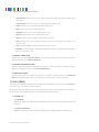
6 ADMIN SCREEN
The “Admin” screen allows the administrator to manage user accounts and assign permission levels for each user.
Click on the Admin tab to access the “Admin” screen from the browser interface.
6.1 USER ACCOUNTS
The Ditto Forensic FieldStation contains two permanent accounts; “admin” and “panel”.The “admin” account
is the Administrator account, and only the Full Name and password may be modified. The “panel” account is
the Front Panel account, and modifies access permissions for functionality that can be accessed through the
LCD screen and navigation buttons on the Ditto Forensic FieldStation.
6.2 PERMISSIONS
6.2.1 Permission Levels
Permission levels on the browser interface are displayed as “FULL”, “AUTH”, or as a hyphen, and as “Full
Access, “Must Authenticate”, and “None”, respectively, when editing or creating a user. “FULL” and “Full
Access” indicate that the user has complete access to the features governed by that permission and is not
required to enter a password. “AUTH” and “Must Authenticate” indicate that the user must authenticate
his credentials with a password in order to change a setting or perform an action that that permission
governs. A hyphen or “None” indicates that the user does not have access to the features governed by
that permission.
6.2.2 Configurable Permissions
The following list of permissions specifies what each controls, and can be configured when adding or
editing a user account. Some permissions for the Administrator and Front Panel accounts will be greyed
out by default.
• Admin: “None” allows access to modify the User Name and Full Name of the Administrator, Front
Panel, and the user’s own account, and allows the user to change his or her own password, but
blocks the user from viewing any account’s permission levels. “Modify Users” enables the user to be
able to modify user accounts, passwords, and permissions (except for the “Admin” permission). “Full
Access” additionally enables the ability to create and delete users and assign the “Admin” permission.
• Config: Governs all non-network configuration settings, including those found in the “System Settings” panel on the “Home” screen and on all tabs on the “Configure” screen.
• NetSettings: Controls access to the network settings on the “Configure” screen.
• Clone: Controls access to the “Clone Source Disk” and “Clone & Image Source Disk” actions.
Protecting Your Digital Assets
TM
28
Ditto Forensic FieldStation User Manual
• Physical Image: Controls access to the “Physical Image Source Disk” and “Clone & Image Source
Disk” actions.
• Logical Image: Controls access to the “Logical Image Source Disk” action.
• Erase: Controls access to the “Erase Destination Disk” action.
• Hash: Controls access to the “Hash Disk” action.
• Snapshot: Controls access to the “Snapshot Disk” action.
• Netview: Controls access to the “Netview Scan” action.
• Abort: Controls access to the ability to abort actions in progress.
• Note: Controls access to the “Comment” buttons in the “Action” and “System Log” panels on the
“Home” screen.
• Logs: Controls the ability to delete log files from the “Logs” screen.
• DiskView: Controls the ability to preview and download files from the suspect drive via the “Disks”
panel on the “Home” screen.
6.3 ADDING A NEW USER
To add a new user, click the Add User button, enter the user’s information, and set the permission levels.
When finished, click on the Commit Add button.
6.4 EDITING AN EXISTING USER
To update a user’s name, password, or permissions, click on the user account under the “User Name” column,
update the information, and then click the Commit Edits button.
6.5 DELETING A USER
To delete a user, click on the user account under the “User Name” column and click on the Delete User
button. Do not click this button unless you are absolutely certain you wish to delete the account.
7 LOGS SCREEN
The “Logs” screen provides information about the Ditto Forensic FieldStation’s actions. Click on the Logs tab to
access the “Logs” screen from the browser interface.
Action logs show the timestamp, the type of action performed, the user who performed the action, and a link to
the “Action Log” screen that provides more information about the performed action.
7.1 ACTION LOG
7.1.1 Settings
Displays the settings of the Ditto Forensic FieldStation that were active when the particular action was
performed.
7.1.2 User Permissions
Displays the permissions of the user that were in place when the particular action was performed.
Protecting Your Digital Assets
TM
29
Ditto Forensic FieldStation User Manual
Figure 24. The “Logs” screen.
7.1.3 Extended Disk Info
This report displays the information of the disk used (which is noted in the title of this report) in the action,
including the interface, model, serial number, capacity, the presence of HPAs (host protected areas) or
DCOs (device configuration overlays), partition information, hdparm information, and S.M.A.R.T information. If multiple disks are used in the action, then multiple reports are created.
7.1.4 Logical Image Report
This report appears in action logs of “Logical Image Source Disk” actions and displays each directory and
file that was imaged, along with their size and any error messages that were generated. If “Validate File
Extensions” is enabled for LIST logical images in the “Configure” screen, it will also log any files in LIST
logical images that have a mismatched file header and extension (see Section 5.5.3). Click on the Export
button to save a copy of the log as an Excel spreadsheet. Click on the Export Suspects button to save a
copy of all of the suspect files where there is a mismatch between the file’s MIME type and file extension.
7.1.5 Netview Report
This report appears in action logs of “Netview Scan” actions and displays summaries of the discovered
hosts, including the IP address, MAC address, and the manufacturer associated with the MAC address
if that information can be determined. The “Hostname” will be blank if a DNS lookup could not associate
the host’s IP address to a name.
8 UTILITIES SCREEN
The “Utilities” screen allows you to perform various miscellaneous functions, including the ability to upgrade
firmware, import customized configurations, remotely reboot the Ditto Forensic FieldStation, modify date and
time settings, and perform a factory reset. Click on the Utilities tab to access the “Utilities” screen from the
browser interface.
Protecting Your Digital Assets
TM
30
Ditto Forensic FieldStation User Manual
Figure 25. The “Utilities” screen.
8.1 SYSTEM MAINTENANCE
8.1.1 Firmware Upgrade
For information on how to upgrade the firmware, see Section 12.
8.1.2 Configuration
You can save and load configurations for the Ditto Forensic FieldStation. The file generated saves a copy of
every customizable setting for the unit.
Save Configuration
To save a configuration, click on the Save Config button. Name the file, and then click Continue to
open a Save As dialog box and save the file to your computer.
Load Configuration
a. Click on the Load Config utton, browse to the .xml configuration file you want to load, highlight
it, and click Open.
b. The “Confirm Import” window will open. Place a check next to each setting you want to load, and
then click Continue. By selecting these settings, you will be overwriting the existing settings, so
be sure to save the current configuration first.
c. The Ditto Forensic FieldStation will import the configuration settings. Click OK when it’s finished.
8.1.3 Other Buttons
• Reboot: Opens a confirmation to reboot the Ditto Forensic FieldStation.
• Date & Time: Allows you to set the current date, time, and timezone. Click the Synchronize button
to sync these settings with your browser’s operating system.
• Factory Reset: Opens a confirmation dialog to return the Ditto Forensic FieldStation to factory settings. Check the Purge Ditto SD card log files box to remove all log files from the SD card in the unit.
You can also use the Front Panel to perform a factory reset. See Section 9.3.
• System Verify: Verifies that the Ditto Forensic FieldStation’s operating system files have not been
modified and places a statement in the system log. If the verification fails, the details can be viewed
by exporting the System Diagnostics.
Protecting Your Digital Assets
TM
31
Ditto Forensic FieldStation User Manual
• Diagnostics: Exports a diagnostics log file in HTML format. The diagnostics log contains information
about the Ditto Forensic FieldStation’s current configuration, including user accounts, kernel messages, logs, process information, disks, PHP errors, and system verify results.
8.2 UPGRADE LOG MESSAGES
This section displays the status log of firmware upgrades and is only visible after a firmware upgrade has been
performed.
8.3 IMPORT LOG MESSAGES
This section displays the status log of configuration file exports and imports and is only visible after a configuration file has been loaded or saved.
9 USING THE FRONT PANEL INTERFACE IN STANDALONE MODE
The Ditto Forensic FieldStation can work as a standalone device with no additional computer required, which can
be useful when working with evidence disks in the field.
The Front Panel interface allows you to clone, physically image, perform a logical image using a Logical Image
Mode, simultaneously clone and image, erase, hash a disk, or perform a snapshot of a disk. You can also adjust
settings, view information about attached disks, or check on the Ditto Forensic FieldStation’s operational status.
The administrator account can assign access permissions to the Front Panel’s actions and settings using the
browser interface.
9.1 HOW TO NAVIGATE
9.1.1 Using the Navigation Buttons
The navigation buttons on the front of the Ditto Forensic FieldStation allow you to navigate through the
menu. Up and Down allow you to scroll through the available options on the Front Panel, while Enter
selects the option and Back goes back to the previous screen. If Quick Start Mode is enabled, press Back
to exit it.
9.1.2 Using a Keyboard
Plug a PC USB keyboard into the USB port on the “Source Inputs” side of the Ditto Forensic FieldStation.
You can navigate using the arrow keys. Press Enter or the Right Arrow keys to select a menu option.
Press the Left Arrow key to back out of a menu or setting. If Quick Start Mode is enabled, you can press
the Escape key to exit it.
NOTE
The Ditto Forensic FieldStation can handle multiple USB devices through a USB hub attached to the
USB port on the “Source Inputs” side of the Forensic FieldStation. However, if multiple keyboards are
connected, keystrokes from all keyboards are processed.
9.2 MENU SCREENS
The Ditto Forensic FieldStation menu consists of the following screens:
9.2.1 Status
The status screen is the default screen. It shows the progress of any current processes. When the Ditto Forensic Field Station is “Idle”, the current firmware of the
unit is also listed on this screen. An example of a status screen is shown in Figure 26.
Protecting Your Digital Assets
TM
Ditto: Idle
Version: 2015Sep19a
(Up/Dn for Menu)
Figure 26. The “Status” screen on the Front Panel LCD.
32
Ditto Forensic FieldStation User Manual
9.2.2 Perform Action
After you adjust settings to your specifications, you are ready to put the Ditto Forensic FieldStation to
work. The “Perform Action” screen lets you start or abort any of the Ditto Forensic FieldStation’s actions
using the current settings.
a. On the “Perform Action” screen, use the Up and Down buttons to cycle through the available actions.
Press Enter to select the one you want.
b. Cycle through the available settings for the action. Press Enter if you wish to modify them.
c. When you are finished modifying settings, scroll down to option that asks you to start the action (ex.
“Start Physical Image?”. Press Enter to begin.
The status and remaining time will be displayed on the LCD screen as the Ditto Forensic FieldStation performs the action. To abort an action, press the Back button. The LCD screen will ask if you wish to abort
the action. Press Enter to confirm, or Back to cancel the abort request.
9.2.3 Investigation Info
Investigator:
C. Walker
The “Investigation Info” lists the current settings that can be modified in the “Investigation Info” section on the “Home” screen of the browser interface. To modify these
settings from the browser interface, see Section 4.2.
Edit (Keyboard)
Editing Fields With A Keyboard
On the “Investigation Info” menu, an “Edit (Keyboard)” menu item will appear
when a keyboard is detected (see Figure 27). You can edit the field currently dis-
Figure 27. The “Investigator” field in the “Investigation
Info” menu on the Front Panel LCD, when a USB keyboard is attached to the Ditto Forensic FieldStation.
played on the LCD by pressing the Enter button on the face of the Ditto Forensic
FieldStation or by pressing Enter or the Right Arrow keys on the keyboard, and
then using the keys to type.
STOP!
Using apostrophes (‘) in the name fields will cause an error when the file or folder name is created. They
should not be used in the Investigation Info fields.
NOTE
Strings longer than 24 characters are displayed with an ellipses character (...) at the right side of the
string.
NOTE
The Ditto Forensic FieldStation can handle multiple USB devices through a USB hub attached to the
USB port on the “Source Inputs” side of the Forensic FieldStation. However, if multiple keyboards are
connected, keystrokes from all keyboards are processed.
Here is a table of the most common keyboard commands:
KEY
COMMAND
Escape
Cancels an edit.
Enter
Begins an edit on a user-editable string or selects the currently-visible
menu option. When pressed while editing a string, it confirms the edit.
Home/End
When editing a string, these keys move the cursor to the beginning/end
of the string, respectively.
Up/Down
Moves through the menu options. When editing a string, they move the
cursor to the beginning/end of the string, respectively.
Delete
Deletes the character currently highlighted by the cursor.
Protecting Your Digital Assets
TM
33
Ditto Forensic FieldStation User Manual
Most Common Keyboard Commands, continued...
KEY
COMMAND
Backspace
Deletes the character immediately behind the cursor.
NumLock
Forces the numbered arrow keys to type numbers when pressed.
CapsLock
Forces all letter keys to type capital letters.
Tab/Shift+Tab/Page Up/
Page Down/Function/Alt/
Windows/Control/Insert
Not handled.
9.2.4 Settings
The “Settings” screen allows you to view and customize the following settings, which are grouped into
three subsections. These settings will be the default settings used in any actions performed.
NOTE
The System Settings below cannot be modified if the Front Panel user account does not have full access
to the “Config” permission, and the Source and Destination Network Settings cannot be modified if
the Front Panel user account does not have access to the “NetSettings” permission. See Section 6 for
information on how to customize the Front Panel user account.
System Settings
•
Physical Image Type: Sets the default physical image type for all actions that create a physical
image. The image types available are E01 or DD.
•
Logical Image Type: Sets the default logical image type for all actions that create a logical image.
The logical image types available are L01, TAR, ZIP, and LIST.
•
Logical Image Mode: Sets the default logical image mode. The logical image modes available
are All Files and Dirs, All Except Windows, All Except Windows Programs (abbreviated as “All
Except W...nd Programs”), All Users - Windows, All Temporary - Windows, All Except Swap and
Hibernate (abbreviated as “All Except S..d and Hibernate”), All Media Files, All Office Files, and All
Financial Files. See Section 4.1.3 under “Logical Image Modes” for a description of each mode.
•
Hash Type: Sets the default hash algorithm that will be used for disk verification and the “Hash
Disk” action. The available options are None, MD5, SHA-1, or MD5 + SHA-1.
•
Erase Mode: Sets the default erase mode that will be used for all actions that require erasing
disks. The available modes are Clear Partition Table, Quick Erase, LBA/Offset Pattern, Custom
Erase, Secure Erase Normal, Secure Erase Enhanced, DOD Clear, DOD Sanitize, NIST800-88
Clear, and NIST800-88 Purge.
•
Default Format: This is the default file system that will be used to format destination disks when
they are used in actions that the Ditto Forensic FieldStation performs. The available formats are
HFS+, FAT32, NTFS, EXT2, EXT3, EXT4, and XFS.
•
HTML Logging: Logs are always saved in .XML format. This option causes the Ditto Forensic
FieldStation to save logs in HTML format as well. The available options are Off and On.
•
DiskView Logging: Logs any action to preview a disk or actions performed while previewing a
disk (i.e. starting or finishing a preview of a disk, starting or finishing a HexView action). The available options are Off and On.
Protecting Your Digital Assets
TM
34
Ditto Forensic FieldStation User Manual
•
LCD/LED Brightness: Sets the relative brightness of the LCDs and LEDs on the face of the Ditto
Forensic FieldStation on a scale of 1 to 255.
•
LCD Prompt Case: Five options may be chosen to modify the case number specified in the
“Investigation Info” section of the “Home” screen in the browser interface. The case number
is included in the log for the requested action. “Disabled” leaves the case number as it is. “Inc/
Dec” allows you to manually increment the case number up or down using the navigation buttons on the face of the Ditto Forensic FieldStation. “AutoInc” automatically increments the case
number, and “AutoInc/Pause” automatically increments the case number, but displays a confirmation prompt the LCD screen before beginning the requested action. These options require a
number to be present on the end of the Case Number specified in the “Investigation Info” section
of the “Home” screen in the browser interface.
•
LCD Prompt Evidence: Five options may be chosen to modify the evidence number specified in
the “Investigation Info” section of the “Home” screen. The evidence number is included in the
log for the requested action. “Disabled” leaves the evidence number as it is. “Inc/Dec” allows
you to manually increment the evidence number up or down using the navigation buttons on the
face of the Ditto Forensic FieldStation. “AutoInc” automatically increments the evidence number,
and “AutoInc/Pause” automatically increments the evidence number, but displays a confirmation
prompt the LCD screen before beginning the requested action. These options require a number
to be present on the end of the Evidence Number specified in the “Investigation Info” section of
the “Home” screen in the browser interface.
•
Quick Start: Enables the “Quick Start” screen on the LCD that appears after you boot or reboot
the Ditto Forensic FieldStation. The settings for this mode may be modified in the “Quick Start”
tab of the “Configure” screen on the browser interface. See Section 5.9.
•
Verify Single: Determines whether individual destination disk are hashed and compared to the
hash value of the source disk’s hash value. The available options are Yes and No.
•
Verify Mirror: Determines whether mirrored destination disks are hashed and compared to the
hash value of the source disk’s hash value(s). You can choose to verify no disks, eSATA-A or
eSATA-B individually, or to verify both disks.
•
Verify Clone & Image: Determines whether cloned and imaged disks are hashed and compared
to the hash value of the source disk’s hash value during a “Clone & Image Source Disk” action.
You can choose to verify no disks, the clone, the image, or both.
•
Log Disk Info: Determines whether S.M.A.R.T. and hdparm disk information is logged before
running an action, after running an action, both, or not at all.
Src (Source) Network Settings
•
Source Network: Enable or disable the source network Ethernet connection.
•
Source MAC Address: Displays the source Ethernet port’s MAC address.
•
Source IP Assignment: Displays the source Ethernet port’s IP assignment method. The available
options are DHCP or Static. An IP address can be manually configuring in the browser interface
(see Section 5.2.2).
Protecting Your Digital Assets
TM
35
Ditto Forensic FieldStation User Manual
•
Source Network Access: Allows you to choose whether or not the Ditto Forensic FieldStation
responds to any network traffic via the source Ethernet port.
•
Source IP Address: Displays the IP address assigned to the source Ethernet port.
Dst (Destination) Network Settings
•
Destination Network: Enable or disable the destination network Ethernet connection.
•
Dest. MAC Address: Displays the destination Ethernet port’s MAC address.
•
Dest. Network Mode: Displays the destination Ethernet port’s networking mode. The available
options are Server, Client (DHCP), or Client (Static IP). “Server” allows you to use enable the
Ditto Forensic FieldStation for use as a server. The network mode can be further configured in the
browser interface (see Section 5.2.3).
•
Dest. IP Address: Displays the IP address assigned to the destination Ethernet port.
•
Dest. Subnet Mask: Displays the subnet mask address assigned to the destination Ethernet
port.
9.2.5 Disk Info
(View) and then Up or Down to scroll through the following information about each
Source eSATA:
HTS5410806XXXXX
79.8GB
connected disk:
No file system
The “Disk Info” screen shows all available disks attached to either the source or
destination ports. Ports are shown only if a disk is connected there. Press Enter
• Model number
Figure 28. The “Disk Info” screen on the Front Panel
LCD.
• Disk capacity
• File system
9.3 FACTORY RESET
To reset the Ditto Forensic FieldStation’s settings back to their factory defaults, press and
hold the Up, Enter, and Down navigation buttons while powering the unit on. The Ditto
Forensic FieldStation will start up and then display the text, “Preparing Factory Reset”
****DITTO****
Initializing...
Preparing Factory Reset
(see Figure 31).
You will then be prompted to confirm your choice to reset the Ditto. Press Enter to continue or Back to cancel.
Figure 29. The “Preparing Factory Reset” screen on
the Front Panel LCD.
You can also use the browser interface to perform a factory reset. See Section 8.1.3.
10 STEALTH MODE
Stealth Mode turns off all LEDs and LCDs on the Ditto Forensic FieldStation. You can enable Stealth Mode by flipping the physical “Stealth Mode” switch on the Destination Outputs side of the Ditto Forensic FieldStation (see
Section 1.2).
You can also enable it from the browser interface. Click on the Configure tab, and then under the “System” tab
change the “Stealth Mode” drop-down box to “Enabled.” Then click Commit Changes.
NOTE
If Stealth Mode is enabled from the browser interface, the physical switch cannot override it.
Protecting Your Digital Assets
TM
36
Ditto Forensic FieldStation User Manual
11 ADVANCED FEATURES AND FUNCTIONS
11.1 NETVIEW SCAN
This type of network probing is very noisy and may trigger any IT related Intrusion Detection Devices (IDSs) on
the network. Please be sure to run this action in a very controlled and isolated environment.
a. Select Netview Scan from the “Action to Perform” drop-down box.
b. Configure the available options, which are detailed below in Section 11.1.1.
c. When you are finished, press the Start button. You should see updates every few seconds that describe
the current scan being executed, the number of hosts discovered, and the progress of the current scan.
Please note that progress estimates are crude and are still being developed. A “Completed” message box
will pop up when the action has finished. Click on the message to continue.
You can view the results of the Netview Scan action by scrolling down to the “System Log” panel on the
“Home” screen. Find and click on the latest link, which will be denoted by a filename with a date/timestamp
format: “S_yyyymmddhhmmss”. Alternatively, you can click on the Logs button from the top menu bar.
The “Netview Report” section contains summaries of the discovered hosts, including the IP address, MAC
address, and the manufacturer associated with the MAC address if that information can be determined. The
“Hostname” will be blank if a DNS lookup could not associate the host’s IP address to a name.
11.1.1 Netview Scan Configuration Options
The following options can be configured before running a Netview Scan:
Interface Selection
The “Interface” drop-down box allows you to tell the Ditto Forensic FieldStation which Ethernet connection to use during the Netview Scan. You can choose either the Source or Destination Ethernet
ports.
STOP!
The selected interface will be used when the scan is started. This may create a heavy network traffic
load and depending on the “Timing” setting in the “Discovery Options” subsection, may alert your IT
department that the network is under some sort of threat. Ensure that the selected interface is attached
to a controlled and isolated network.
Figure 30. The “Action” section on the “Home” screen, showing
the options available for the “Netview Scan” action.
Protecting Your Digital Assets
TM
37
Ditto Forensic FieldStation User Manual
IP Scan Range
By default the last octet of the IP address of the selected interface will be scanned. You may change
this value and enter a list of IP address, a range of IP addresses, or a combination of both. Click the
“Reset” icon to reset the IP Scan Range back to its default value.
Examples:
1.
Range: 10.10.10.0-255
•
2.
Range 2: 10.10.10-12.0-255
•
3.
Will only scan IP address 10.10.10.1
List 2: 10.10.10.2,10.10.10.3
•
5.
Scans addresses 10.10.10.0-255, 10.10.11.0-255, and 10.10.12.0-255.
List: 10.10.10.1
•
4.
Scans the addresses 10.10.10.0 through 10.10.10.255.
Will scan only hosts 10.10.10.2 and 10.10.10.3
Combo: 10.10.10.1,10.10.10.2,10.10.10.50-100
•
Will scan hosts 10.10.10.1, 10.10.10.2 and hosts 10.10.10.50 through 10.10.10.100.
Discovery Options
There are three optional host (machine) discovery options and one “No Ping” port scan option available. By default, the “Ping Echo” option is enabled and will suffice for most use cases. Some machines
may be configured to ignore pings and not respond, so there are two other specialized Ping options
which may be useful. Click the “Reset” icon to reload the default settings.
•
Ping Echo: Sends a standard ICMP echo request to each IP address.
•
Ping Timestamp: Sends a request for a timestamped ICMP packet.
•
Ping Netmask: Sends a request for the destination’s subnet mask using an ICMP packet.
•
No Ping: Skips host discovery and forces a port scan, which is useful when the hosts appear
to be down.
•
Timing: Selects a timing interval for scanning a network. “3” is the default setting. Lower
numbers are slower and will help you avoid triggering an intrusion detection alert, and higher
numbers are faster but may be less accurate, and may cause intrusion detection alerts.
TCP Options
NetView can optionally scan the specified hosts for open TCP ports. By default, this feature is not
enabled. Check the box next to “TCP Options” to enable this feature and expand more options. Click
the “Reset” icon to reset all TCP Options back to their default values.
•
Ports: By default, TCP ports for commonly used services as well as services to which the Ditto
Forensic FieldStation may be able to connect are entered into this text box, including ports
for NFS, iSCSI, and Samba. Only ports entered into this text box will be scanned. NetView IP
port ranges may be specified as any combination of lists and ranges. Valid port numbers are
between 1 and 65535 (inclusive). A list is in the form: 80,22,23. A range is in the form: 1-40.
Both may be combined to form: 22,23,40-50,80,90-91.
Protecting Your Digital Assets
TM
38
Ditto Forensic FieldStation User Manual
•
Syn Scan: Syn Scan is selected by default and is appropriate for most use cases. The Ditto
Forensic FieldStation generates raw IP packets and monitors for responses. This type of scan is
also known as “half-open scanning” since it does not open a full TCP connection.
•
Connect Scan: The Ditto Forensic FieldStation uses a full system-level TCP connection in order
to determine what ports are available on the host network. This scan should only be performed
by advanced users.
NOTE
The more ports being scanned, the longer the scan will take.
UDP Options
NetView can optionally scan the specified hosts for open UDP ports. By default, this feature is not
enabled. Check the box next to “UDP Options” to enable this feature. Click the “Reset” icon to reset
the UDP option back to its default values.
Ports: By default, UDP ports for commonly used services as well as services to which the Ditto
Forensic FieldStation may be able to connect are entered into this text box, including NFS, iSCSI, and
Samba. Only ports entered into this text box will be scanned. NetView IP port ranges may be specified as any combination of lists and ranges. Valid port numbers are between 1 and 65535 (inclusive).
A list is in the form: 80,22,23. A range is in the form: 1-40. Both may be combined to form: 22,23,4050,80,90-91.
NOTE
UDP port scanning takes much longer than TCP port scanning due to the fact that open and filtered
ports do not typically respond to queries. Therefore, any UDP port scanner will spend time retransmitting its query in case the query or response was lost. Furthermore, while closed ports do usually
respond with ICMP port unreachable messages, hosts tend to limit the number of those messages
sent per second, resulting in further delay.
Netview Tips
1.
See Nmap.org for general information about network scanning.
2.
Keep your IP address lists/ranges short. This will mean faster scans and less network traffic.
3.
Keep your port lists/ranges short. This will also mean faster scans and less network traffic.
4.
Start by deselecting the TCP and UDP scans. Just scanning for the presence of hosts is much
quicker than running TCP and UDP scans on a network with an unknown number of machines.
Once you have a list of discovered machines, then you can decide whether to TCP and/or UDP
scan them all or scan only a subset at a time.
5.
TCP scanning must be enabled in order to detect the target’s operating system.
11.2 TARGET MODE: REMOTELY ACCESS DISKS ATTACHED TO THE DITTO FORENSIC
FIELDSTATION WITH THIRD PARTY SOFTWARE
Disks attached to Ditto Forensic FieldStation may be mounted on your computer as iSCSI devices for use with
third party data acquisition tools. The machine this software is installed on does not have to be physically connected to the Ditto Forensic FieldStation, but rather the software may be run remotely from a separate location within the same network. To do so, you will need to put the Ditto Forensic FieldStation into Target Mode.
a. On the “Home” Screen, navigate down to the bottom of the “Disks” panel and select the Target Mode
button.
Protecting Your Digital Assets
TM
39
Ditto Forensic FieldStation User Manual
b. Check the boxes in the iSCSI column next to the disk(s) that you wish to mount on your computer as iSCSI
device(s).
c. Check Enable iSCSI and SMB authentication if you wish to require authentication in order for iSCSI
initiator software to connect to the selected disk(s). Then input your desired credentials.
d. Press the OK button.
You can now mount the disk(s) you selected in the steps above to your computer. Use the Ditto Forensic
FieldStation’s IP address in your iSCSI initiator software in order to attach to it. Initiators can vary, but typically you’ll add the IP address to the “Discovery” section of your initiator.
11.3 USING ISCSI DEVICES
11.3.1 Remotely Access an iSCSI Device
To connect to an iSCSI device that exists on your network, follow these directions.
a. Ensure that the Ethernet port through which the Ditto Forensic FieldStation is
connected to your network is properly configured for use with your network (see
Section 5.2). Unless you have manually configured the Ditto Forensic FieldStation’s network settings before, you most likely do not have to change anything.
If you are directly connecting the iSCSI device to the Ditto Forensic FieldStation,
then see Section 11.3.2.
b. On the “Home” Screen, navigate down to the bottom of the “Disks” panel.
c. Click the Source Network button if you want to attach the iSCSI device to the
Ditto Forensic FieldStation as a write-blocked source device, or click the Desti-
Figure 31. The “Target Mode” window is used to allow
computers and third party software to remotely connect via iSCSI to disks connected to Ditto.
nation Network button if you want to attach the iSCSI device as a read/writeenabled destination.
d. Click on the iSCSI tab if it is not already selected.
e. Type the iSCSI device’s IP address into the “Target Host” text field.
f. Type in the port number of the target iSCSI volume into the “Port” text field if the number is different
than the default value of ‘3260’. If you don’t know the port number, leave it as the default value.
g. Click the Discover button. The Ditto Forensic FieldStation will detect any IQNs (iSCSI Qualified
Names) attached to the IP address.
h. Select the IQN you wish to attach to the Ditto Forensic FieldStation from the drop-down box.
i. If authentication is required to connect to the IQN, click the Advanced... button and input the appropriate credentials, including the user name, password, and domain. Otherwise, continue to Step J.
j. Click the Add button. The IQN will now appear in the list below.
k. Repeat steps E through J to add more IQNs. When you are finished, click Close.
The iSCSI disk(s) have now been added to the list of Disks, allowing you to perform actions on them like
you would any other disk.
Protecting Your Digital Assets
TM
40
Ditto Forensic FieldStation User Manual
11.3.2 Directly Connect an iSCSI Device to the Ditto Forensic FieldStation
If you do not wish to connect an iSCSI device to your network (for example, it may be a suspect device
with unknown properties), you can directly connect the device to the Ditto Forensic FieldStation and isolate it from the rest of your network. There are two methods for doing so. Once you have connected the
device, continue down to the third subsection, “Adding an iSCSI Disk to the ‘Disks’ Panel”.
Connect via the Source Ethernet Port
Follow these instructions if the iSCSI device you are attaching to the Ditto Forensic FieldStation is a
suspect device. You’ll need to connect the iSCSI device to the source Ethernet port and manually configure the IP address of both the Ditto Forensic FieldStation and the iSCSI device.
Manually set the Ditto Forensic FieldStation’s IP address.
a. Click on the Configure tab at the top of the page, and then select the Network tab.
b. In the “Source Network” section, select Static IP from the drop-down box
underneath the MAC address.
c. Type in the desired IP address and subnet mask into the appropriate fields.
Do not fill in the Gateway, Primary DNS Server, or Secondary DNS Server
unless directed to do so by your network administrator.
d. Click Commit Changes.
Figure 32. The “Source Network” section on the “Configure” screen’s “Network” tab.
Manually set the iSCSI device’s IP address, subnet mask, and gateway. The first
three octets of the IP address must be identical to the first three octets of the Ditto Forensic FieldStation’s IP address. The fourth octet must be different, and must be any other number between 1 and
255. The subnet mask must be identical to the Ditto Forensic FieldStation’s subnet mask. The gateway
must also be set as the Ditto Forensic FieldStation’s IP address.
Based on the IP address configuration of a Ditto Forensic FieldStation that’s displayed in Figure 32, a
valid configuration for an iSCSI device would be as follows:
IP address: 10.10.10.100
Subnet mask: 255.255.255.0
Gateway: 10.10.10.1
After these settings are configured for the Ditto Forensic FieldStation and the iSCSI device, ensure
that the iSCSI device is connected to the source Ethernet Port. Then continue to the “Adding an iSCSI
Volume to the ‘Disks’ Panel” subsection below.
Connect via the Destination Ethernet Port
Follow these instructions if you will be transferring evidence or other data to the iSCSI device. First,
ensure that the destination Ethernet port is configured to act as a server.
a. Click on the Configure tab at the top of the page, and then select the Network tab.
b.
In the “Destination Network” section, select Server from the drop-down box underneath the
MAC address. Do not customize the default server configuration unless directed to do so by
your network administrator.
c.
Click Commit Changes.
Protecting Your Digital Assets
TM
41
Ditto Forensic FieldStation User Manual
Now connect the iSCSI Device to the destination Ethernet port. The iSCSI device will be assigned a
new IP address if the iSCSI device is configured to obtain a new IP address from DHCP, which will the
case for most devices. If no IP address is assigned, you will need to configure the iSCSI device to use
DHCP. If that is not possible, contact your network administrator.
Once the iSCSI device is assigned an IP address, continue to the “Adding an iSCSI Volume to the
‘Disks’ Panel” subsection below.
Adding an iSCSI Disk to the “Disks” Panel
On the “Home” Screen, navigate down to the bottom of the “Disks” panel.
a. Click the Source Network button if you want to attach the iSCSI device to
the Ditto Forensic FieldStation as a write-blocked source device, or click the
Destination Network button if you want to attach the iSCSI device as a read/
write-enabled destination.
b. Click on the iSCSI tab if it is not already selected.
c. Type the iSCSI device’s IP address into the “Target Host” text field.
d. Type in the port number of the target iSCSI volume into the “Port” text field
Figure 33. The “Source Network” window’s iSCSI tab
allows you to connect iSCSI devices to the Ditto via
the source Ethernet port. The “Destination Network”
tab looks similar and does the same via the destination
Ethernet port.
if the number is different than the default value of ‘3260’. If you don’t know the port number, leave
it as the default value.
e. Click the Discover button. The Ditto Forensic FieldStation will detect any IQNs (iSCSI Qualified
Names) attached to the IP address.
f. Select the IQN you wish to attach to the Ditto Forensic FieldStation from the drop-down box.
g. If authentication is required to connect to the IQN, click the Advanced... button and input the
appropriate credentials, including the user name, password, and domain. Otherwise, continue to
the next step.
h. Click the Add button. The IQN will now appear in the list below.
i. Repeat steps C through H to add more IQNs. When you are finished, click Close.
The iSCSI disk(s) have now been added to the list of Disks, allowing you to use the Ditto Forensic
Fieldstation to perform actions on them like you would any other disk.
11.3.3 Properly Remove an iSCSI Device
This process prevents timeout issues where the Ditto Forensic FieldStation will attempt to connect to
iSCSI volumes that no longer are connected to it. On the “Home” Screen, navigate down to the bottom
of the “Disks” panel.
a. Click the Source Network button if your iSCSI device is connected via the source Ethernet Port, or
click the Destination Network button if your iSCSI device is connected via the destination Ethernet
Port.
b. Click on the iSCSI tab if it is not already selected.
c. Under the “iSCSI Source Connections” or the “iSCSI Destination Connections” section, check the
boxes next to the IQN(s) you want to remove and click the Remove button.
d. Physically disconnect the iSCSI device from the Ditto Forensic FieldStation.
Protecting Your Digital Assets
TM
42
Ditto Forensic FieldStation User Manual
11.4 USING NFS AND SMB (SAMBA) SHARES
11.4.1 Connect to NFS and SMB Shares
a. On the “Home” Screen, navigate down to the bottom of the “Disks” panel.
b. Click the Source Network button if the Ditto Forensic FieldStation is connected to your network via
the source Ethernet Port, or click the Destination Network button if it is connected via the destination Ethernet Port.
c. Click on the NFS tab or the SMB tab, depending on which type of share you are connecting to.
d. Type the server name into the Server text field.
e. If you are connecting to an SMB share, select the appropriate protocol from the “Protocol” drop-down
box. If you don’t know the correct protocol, leave it as the default value of ‘SMBv1’.
f. Click the Show Shares button. The Ditto Forensic FieldStation will detect any shares attached to the
server.
g. Select the share you wish to attach to the Ditto Forensic FieldStation from the drop-down box.
h. If you are connecting to an SMB share and authentication is required, click the Advanced... button
and input the appropriate credentials, including the user name, password, and domain. If the SMB
share does not require authentication or you are connecting to an NFS share, continue to the next
step.
i. Click the Add button. The share will now appear in the list below.
j. Repeat steps C through I to add more shares. When you are finished, click Close.
The share(s) have now been added to the list of Disks, allowing you to perform actions on them like you
would any other disk.
11.4.2 Remove an NFS or SMB (Samba) Share
a. On the “Home” Screen, navigate down to the bottom of the “Disks” panel.
b. Click the Source Network button if the Ditto Forensic FieldStation is connected to your network via
the source Ethernet Port, or click the Destination Network button if it is connected via the destination Ethernet Port.
c. Click on the NFS tab or SMB tab, depending on the which type of share you are removing.
d. Under the “iSCSI Source Connections” or the “iSCSI Destination Connections” section, check the
boxes next to the share(s) you want to remove and then click the Remove button.
11.5 ADDING A NEW LOGICAL IMAGE MODE
If you want to add your own Logical Image Mode selection, you must create a DittoAutoSelect directory
on your SDCard first. Then you can add one or more auto select XML files to that directory. You may also add
subdirectories that contain one or more auto select XML files to the DittoAutoSelect directory. Insert the SD
Card into the Ditto Forensic FieldStation and your custom Logical Image Modes will then be selectable when
configuring a “Logical Image Source Disk” action.
Protecting Your Digital Assets
TM
43
Ditto Forensic FieldStation User Manual
11.5.1 DittoAutoSelect XML File Structure
<?xml version=”1.0” encoding=”UTF-8”?>
<!-- All attributes must be in single quotes if they contain double quotes.
-->
<dittoAutoSelect
xmlns:xsi=”http://www.w3.org/2001/XMLSchema-instance”
>
xsi:noNamespaceSchemaLocation=”autoSelect.xsd”
<select title=”Example Title”>
<include path=”*”>
<name>*.jpeg</name>
<name>*.jpg</name>
<name>*.m4*</name>
</include>
<!-- .m4a, .m4v, etc -->
<exclude path=”Windows”/>
</select>
</dittoAutoSelect>
The name of the auto select XML file can be any legal file name with a .xml file extension. Each auto
select XML file may contain one or more <select title=”...”> blocks. The select block’s title will appear at
the bottom of the Logical Image Mode selection list prepended with “SDCard/” followed by the subdirectory’s name, if any.
Each select block may contain one or more <include path=”...”> and/or <exclude path=”...”> blocks. The
include/exclude block’s path (case-insensitive) may contain wildcard characters and will be included in or
excluded from the auto selection, respectively.
Each include block may contain zero or more <name>...</name> blocks, which specify a file name to be
included in the auto selection. File names are case-insensitive and may contain wildcard characters to
specify a set of file names. Exclude blocks cannot contain name blocks.
NOTE
You cannot remove existing selections from the Logical Image Mode list.
To download an XML Schema that can be used to validate your auto select XML file, type the following
into the address bar of an Internet browser, where <IP Address> is the IP address of your Ditto Forensic
FieldStation: http://<IP Address>/data/DittoAutoSelect/autoSelect.xsd
12 UPGRADING FIRMWARE
Firmware upgrades are made available on CRU’s website at www.cru-inc.com/support/software-downloads/dittofirmware-updates/. There are three methods to upgrade your Ditto Forensic FieldStation’s firmware.
METHOD 1: COPY AND PASTE A LINK
a. Ensure that the Ditto Forensic FieldStation is connected to a network with Internet access.
b. Go to the firmware updates webpage and scroll down to the “Ditto Firmware Links” section. Copy the
URL of the firmware you wish to use to upgrade.
c. Log into your Ditto Forensic FieldStation’s browser interface and navigate to the “Utilities” screen.
Protecting Your Digital Assets
TM
44
Ditto Forensic FieldStation User Manual
d. Paste the link into the top text field and click the Firmware Upgrade button.
e. When it asks you to confirm the retrieval of the upgrade file, click Continue.
f. The Ditto Forensic FieldStation will download the file to itself. Once downloaded, it will ask you to confirm
the upgrade. Click Continue. After the upgrade is finished, cick OK.
g. The LCD panel of the Ditto Forensic FieldStation will ask you to reboot. Press the Enter button on the face
of the unit to reboot, or click on the Reboot button on the “Utilities” screen.
METHOD 2: DOWNLOAD TO YOUR COMPUTER
a. Go to the firmware updates webspage and scroll down to the “Ditto Firmware Links” section.
b. Click on the firmware you wish to use to upgrade to download the file. Save the file in a convenient location.
c. Log into your Ditto Forensic FieldStation’s browser interface, navigate to the “Utilities” screen, and click
on the top Upload... button.
d. Locate the firmware file you just downloaded, select it, and click Open.
e. Click on the Firmware Upgrade button.
f. The Ditto Forensic FieldStation will upload the file to itself. Once uploaded, it will ask you to confirm the
upgrade. Click Continue. After the upgrade is finished, cick OK.
g. The LCD panel of the Ditto Forensic FieldStation will ask you to reboot. Press the Enter button on the face
of the unit to reboot, or click on the Reboot button on the “Utilities” screen.
METHOD 3: UPLOAD VIA A USB THUMB DRIVE
a. Go to the firmware updates webspage and scroll down to the “Ditto Firmware Links” section.
b. Click on the firmware you wish to use to upgrade to download the file. Save the file to a USB thumb drive.
c. Insert the thumb drive into the source side USB port of the Ditto Forensic FieldStation.
d. The Ditto Forensic FieldStation will immediately scan the thumb drive and display a list on the LCD screen
of all firmware files found on the drive. Use the navigation buttons on the face of the unit to move the
blinking cursor to the firmware that you wish to use to upgrade, and then press Enter.
e. The Ditto Forensic FieldStation’s firmware will be upgraded. The LCD panel of the Ditto Forensic FieldStation will ask you to reboot. Press Enter to reboot.
Protecting Your Digital Assets
TM
45
Ditto Forensic FieldStation User Manual
13 TECHNICAL SPECIFICATIONS
Product Name
Ditto Forensic FieldStation
•
•
•
•
Data Interface Types &
Speeds
eSATA: up to 3 Gbps
1000BASE-T EtherNet: up to 1 Gbps
PATA/IDE: up to 133 MB/s
USB 2.0: up to 480 Mbps
Supported Disk Types
2.5” and 3.5” rotational or solid state hard disks
SD Card Slot Support
SD, SDHC (MMC, mini-SD, and microSD are compatible with adapters)
Wifi USB Adapter Support
• Wifi adapters with Atheros chipsets, and some Realtek chipsets
Data Connectors
•
•
•
•
•
•
Three (3) eSATA ports
Two (2) 1000BASE-T Ethernet connectors
One (1) PATA/IDE connector
One (1) USB 2.0 connector
One (1) SD Card slot
One (1) Ditto Expansion Module connector
Write-Blocked Data Inputs
eSATA, PATA/IDE, USB 2.0. Source-side Ethernet port. Other input types supported with Ditto
Expansion Modules or drive adapters.
Data Outputs
Two (2) eSATA operable as single, dual, or mirrored. Both 1000BASE-T Ethernet ports.
Supported
File Systems
ext2, ext3, ext4, FAT32, HFS+, NTFS, XFS
• Four-line LCD controlled with four soft-touch menu navigation buttons or USB keyboard
• Browser-based Ditto interface allows for direct operation, remote operation, and administration
User Interface
LED Indicators
Power in 5V/12V, USB, Source Network, IDE, eSATA, Expansion, HPA/DCO, Destination Network, eSATA A, eSATA B
Stealth Mode
Turns off all lights (LEDs/LCD)
Browser Compatibility
Internet Explorer, Firefox, Safari, Chrome, Opera
Physical Image Types
DD, E01
Logical Image Types
L01, LIST, TAR, ZIP
Image/Clone Output
Modes
Single disk image, single disk clone, image and clone, image to mirrored disks, clone to mirrored
disks, logical image to single disk, logical image to mirrored disks
Hash Modes
None, MD5, SHA-1, MD5 + SHA-1, enabled during imaging and cloning operations. Hashing while
using both MD5 + SHA-1 significantly reduces performance.
Erase Modes
Clear Partition Table, Quick Erase, Custom Erase, Secure Erase Normal, Secure Erase Enhanced,
DoD Clear, DoD Sanitize, NIST800-88 Clear, NIST800-88 Purge
External material
All-aluminum construction
Operating Humidity
5% to 95%, non-condensing
Power Switch
2 position: On / Off
Power Inputs
40W 12V 3.33A DC barrel connector (center pin positive), 15-pin standard SATA power
Protecting Your Digital Assets
TM
Compliance
•
•
•
•
EMI Standard: FCC Part 15 Class A
CE
EMC Standard: EN55022, EN55024
C-Tick
Shipping Weight
5 lbs (2.3 kg)
Product Dimensions
4.92in x 6.77in x 1.72in (125mm x 172mm x 43.7mm)
Technical Support
Your investment in CRU products is backed up by our free technical support for the lifetime of
the product. Contact us through our website, www.cru-inc.com/support or call us at 1-800-2609800 or +1-360-816-1800.
©2012-2014 CRU Acquisition Group, LLC. ALL RIGHTS RESERVED.
This User Manual contains proprietary content of CRU Acquisition Group, LLC (“CRU”) which is protected by copyright, trademark, and other intellectual property rights.
Use of this User Manual is governed by a license granted exclusively by CRU (the “License”). Thus, except as otherwise expressly permitted by that License, no part of this User Manual
may be reproduced (by photocopying or otherwise), transmitted, stored (in a database, retrieval system, or otherwise), or otherwise used through any means without the prior express
written permission of CRU.
Use of the full Ditto Forensic FieldStation product, including, without limitation, its web interface, is subject to all of the temrs and conditions of this User Manual and the above referenced
License.
This Ditto Forensic FieldStation product and User Manual are provided on a RESTRICTED basis. Use, duplication, or disclosure by the US Government is subject to restrictions set forth in
Paragraph (b) of the Commercial Computer Software License clause at 48 CFR 42.227-19, as applicable.
CRU®, Ditto®, and WiebeTech® (collectively, the “Trademarks”) are trademarks owned by CRU and are protected under trademark law. Nmap is a registered trademark of Insecure.Com,
LLC in the United States and/or other countries. Excel is a registered trademark of Microsoft in the United States and/or other countries. EnCase is a registered trademark of Guidance
Software in the United States and/or other countries. This User Manual does not grant any user of this document any right to use any of the Trademarks.
Product Warranty
CRU warrants this product to be free of significant defects in material and workmanship for a period of three years from the original date of purchase. CRU’s warranty is nontransferable
and is limited to the original purchaser.
Limitation of Liability
The warranties set forth in this agreement replace all other warranties. CRU expressly disclaims all other warranties, including but not limited to, the implied warranties of merchantability
and fitness for a particular purpose and non-infringement of third-party rights with respect to the documentation and hardware. No CRU dealer, agent, or employee is authorized to make
any modification, extension, or addition to this warranty. In no event will CRU or its suppliers be liable for any costs of procurement of substitute products or services, lost profits, loss
of information or data, computer malfunction, or any other special, indirect, consequential, or incidental damages arising in any way out of the sale of, use of, or inability to use any CRU
product or service, even if CRU has been advised of the possibility of such damages. In no case shall CRU’s liability exceed the actual money paid for the products at issue. CRU reserves
the right to make modifications and additions to this product without notice or taking on additional liability.
FCC Compliance Statement: “This device complies with Part 15 of the FCC rules. Operation is subject to the following two conditions: (1) This device may not cause harmful interference,
and (2) this device must accept any interference received, including interference that may cause undesired operation.”
This equipment has been tested and found to comply with the limits for a Class A digital device, pursuant to Part 15 of the FCC Rules. These limits are designed to provide reasonable
protection against harmful interference when the equipment is operated in a commercial environment. This equipment generates, uses, and can radiate radio frequency energy and, if not
installed and used in accordance with the instruction manual, may cause harmful interference in which the user will be required to correct the interference at their own expense.
In the event that you experience Radio Frequency Interference, you should take the following steps to resolve the problem:
1)
Ensure that the case of your attached disk is grounded.
2)
Use a data cable with RFI reducing ferrites on each end.
3)
Use a power supply with an RFI reducing ferrite approximately 5 inches from the DC plug.
4)
Reorient or relocate the receiving antenna.
FOR OFFICE OR COMMERCIAL USE
Protecting Your Digital Assets
TM
For more information,
visit the CRU web site.
www.cru-inc.com
Part Number: A9-000-0028 Rev 3.1