1
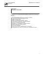
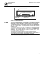
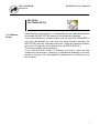
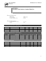
MicroSHADOW
Research
ROMShock User’s Manual
ROMShock User’s Manual
Document Number [ 0024-D-0001-ENG / A ]
Release Date 16 Set 1997
Copyright 1997 MicroSHADOW Research
1
MicroSHADOW
Research
ROMShock User’s Manual
AVVISO
Le informazioni contenute nel presente manuale possono essere soggette a modifiche
senza nessun preavviso. MicroSHADOW Research non si assume alcuna responsabilità
per eventuali errori o inesattezze nella documentazione. Nello stesso modo la
MicroSHADOW Research non è responsabile in alcun modo dei danni causati da difetti,
guasti o scelte di progetto dell’ HARDWARE del prodotto ROMShock. Questo implica
che nessun tipo di garanzia, per quanto suddetto, può essere rivendicata.
Se non specificato diversamente, ogni riferimento a società, nomi e dati utilizzati nelle
riproduzioni delle schermate e negli esempi è puramente casuale ed ha il solo scopo di
illustrare l’uso del prodotto ROMShock. Nessuna parte di questo manuale può essere
riprodotta in qualsiasi forma o mezzo elettronico senza autorizzazione scritta della
MicroSHADOW Research
NOTICE
The information contained in this manual is subject to change without notice.
MicroSHADOW Research assumes no responsibility or liability for any errors or
inaccuracies in the documentation. In the same way MicroSHADOW Research assumes
no liability for any damage resulting from defects, circuitry damage or design’s choice of
ROMShock HARDWARE. It makes no warranty of any kind (express, implied or statutory)
with respect to this publication, and expressly disclaims any and all warranties of
merchantability, fitness for particular purposes and noninfringement of third party rights.
Any referement to Corporations, names and data used in screen’s reproduction are purely
casual and are intented for tutorial purpose use only. No part of this manual may be
photocopied or reproduced in any form or by electronic media without prior written
authorization from MicroSHADOW Research.
Microsoft, MS-DOS, Windows, Windows95 are registered trademark of Microsoft
Corporation.
Intel is a registered trademark of Intel Corporation.
Motorola is a registered trademark of Motorola Corporation
2
MicroSHADOW
Research
ROMShock User’s Manual
IMPORTANTS
Plug and unplug the emulation PODs with TARGET SYSTEM
switched off.
When possible power the emulator through the TARGET SYSTEM (
Power Option JUMPER shorted and external power connector not used
). This is a good method to avoid LATCH-UP problems.
When you are using external power feature you must supply power to
emulator and TARGET SYSTEM at the same time.
3
MicroSHADOW
Research
ROMShock User’s Manual
SECTION 1
GENERAL FEATURES
ROMShock is an 8/16Bit ROM/EPROMEMULATOR with the following
features :
8 Bit EPROM EMULATION from 27x256 to 27x080
16 Bit EVEN/ODD EPROM EMULATION
JEDEC standard POD
RESET and NEGATED RESET outputs
CENTRONICS PARALLEL standard interface
External or parasitic power supply
Windows 3.1 or Windows95 software interface
EXADECIMAL/ASCII dump window
DOS version software
Binary, Intel STD/EXT and Motorola S file formats
High transfer rate ( about 4.5 seconds for ½ Megabyte of code )
4
MicroSHADOW
Research
ROMShock User’s Manual
SECTION 2
KNOW THE EMULATOR
LOADING
INDICATOR
POWER
INDICATOR
EVEN POD
CONNECTOR
ODD POD
CONNECTOR
Figure 1 - The emulator front panel
2.1 Front
Panel
On the front panel two 34-pin flat cable connectors are present. These
connector are called EVEN and ODD PODs.
During a 8 Bit EPROM emulation ( Mode SMALL 5-9 ) only the EVEN
POD must be used.
In the modality 16 BIT EVEN/ODD 16 BIT both the EVEN/ODD POD are
used ( See section 5.1 ).
There are special modalities called LARGE MODES ( Mode 10-15 )
where both EVEN/ODD pods are used but a special adapter ADPLARGE 28-32, included in the kit, is required.
The POWER indicator indicate the presence of the power, the LOADING
indicator is active during the loading session. Moreover this indicator
signals a level change on the RST/RST# outputs in the emulator back.
5
MicroSHADOW
Research
ROMShock User’s Manual
RST# & RST OUTPUTS
POWER OPTION JUMPER
PARALLEL PORT
CONNECTOR
EXTERNAL POWER
CONNECTOR
Figure 2 - The emulator back panel
2.2 Back
The 25-PIN connector must be connected to the personal computer’s
parallel port. ( A 80cm flat cable is included in the kit for this purpose ).
The two-poles connector present at the extreme left of the panel give the
two RST e RST# outputs. The yellow-green crocodile cable must be
plugged in here.
The connector placed at the right of the panel gives the external power
capability . Use the black-red cable for this feature. ( REMEMBER TO
UNSHORT THE POWER OPTION JUMPER WHEN USING THE
EXTERNAL POWER METHOD ).
The power option jumper is placed at the left of 25PIN connector.
This JUMPER must be shorted when target-parasithic power method is
used. Open this JUMPER when external power is supplied.
NOTE : EXTERNAL POWER MUST BE 5V DC
6
MicroSHADOW
Research
ROMShock User’s Manual
SECTION 3
SOFTWARE SETUP
3.1 Software
Setup
Software setup in Windows 3.x / Windows95 can be made launching the
executable file SETUP.EXE present in the distribution diskette.
If you have Windows 3.x based system you can use FILE MANAGER, if
you have Windows95 you can start the setup process selecting the
SETUP.EXE from the computer resources. ( Open the resource window,
open the 3.5 floppy drive and double click on SETUP.EXE file ).
The setup process is self-explanied..
If you need the DOS version of software you have to copy the files
contained in the directory <\dosonly> of distribution diskette in your work
directory. However, the executable file datazap!.exe is sufficent to use
the emulator.
7
MicroSHADOW
Research
ROMShock User’s Manual
SECTION 4
CONNECTING THE EMULATOR
ROMShock has differents connecting methods. These methos change in
accodance with of desidered emulation mode. For further information on
emulation modes see the SECTION 5 - EMULATOR WORKING
MODES.
4.1 SMALL MODE The SMALL MODE permits to EMULATE, using the of EVEN POD only,
all the devices from 27x256 to 27x040.
See Figure 3 for the connecting details.
PARALLEL PORT CONNECTION
RESET PIN
EMULATOR
EVEN POD
MICROPROCESSOR
Figure 3 - Connecting in 8 BIT SMALLMODE
8
MicroSHADOW
Research
4.2 EVEN /ODD
16 BIT MODE
ROMShock User’s Manual
The 16 Bit EVEN/ODD mode permits to EMULATE at the same time two
EPROM from 27x256 to 27x040 in modality EVEN/ODD.
Pay attention! The ODD POD of ROMShock can’t be used to emulate
devices independently . See SECTION 5 for further information on
EVEN/ODD functions.
PARALLEL PORT CONNECTION
EMULATOR
RESET PIN
ODD POD
EVEN POD
MICROPROCESSOR
Figure 3 - 16 Bit EVEN/ODDconnecting
4.3
8 BIT LARGE
MODE
The LARGE MODE is a special working mode that permits the
extensions of the emulation capability up to 1 Mbyte allowing emulation
of devices from 27x256 to 27x080. The LARGE MODE requires a
particular adapter ADP-LARGE 28-32 included in the KIT
For further detail on this working mode see the SECTION 5.
PARALLEL PORT CONNECTION
RESET PIN
LARGE ADAPT.
EMULATOR
EVEN POD
ODD POD
uP
Figure 5 - 8 Bit LARGEMODE connecting
9
MicroSHADOW
Research
ROMShock User’s Manual
SECTION 5
EMULATORE WORKING MODES
5.1
The 16
emulation
modes
ROMShock has 16 EMULATION MODES ( 0..15 ). You have to
configure some parameters to obtain the desired EMULATION
functionality. Use the table 1 to configure ROMShock.
Modes
16 BIT EVEN/ODD - 512
16 BIT EVEN/ODD - 1024
16 BIT EVEN/ODD - 2048
16 BIT EVEN/ODD - 4096
16 BIT EVEN/ODD - 8192
SMALL 8 BIT - 256
SMALL 8 BIT - 512
SMALL 8 BIT - 1024
SMALL 8 BIT - 2048
SMALL 8 BIT - 4096
LARGE 8 BIT - 256
LARGE 8 BIT - 512
LARGE 8 BIT - 1024
LARGE 8 BIT - 2048
LARGE 8 BIT - 4096
LARGE 8 BIT - 8192
Used PODS
** POD 1 / POD 2
** POD 1 / POD 2
POD 1 / POD 2
POD 1 / POD 2
* POD 1 / POD 2
** POD 1
** POD 1
POD 1
POD 1
* POD 1
POD1 / POD 2
POD1 / POD 2
POD1 / POD 2
POD1 / POD 2
POD1 / POD 2
* POD1 / POD 2
Total
KBYTES
Organiz.
64
128
256
512
1024
32
64
128
256
512
32
64
128
256
512
1024
2 x 27C256
2 x 27C512
2 x 27C010
2 x 27C020
2 x 27C040
1 x 27C256
2 x 27C512
1 x 27C010
1 x 27C020
1 x 27C040
1 x 27C256
1 x 27C512
1 x 27C010
1 x 27C020
1 x 27C040
1 x 27C080
ADP
LARGE
28-32
UNUSED
UNUSED
UNUSED
UNUSED
UNUSED
UNUSED
UNUSED
UNUSED
UNUSED
UNUSED
JP1 1-2
JP1 1-2
JP1 2-3
JP1 2-3
JP1 2-3
JP1 2-3
28 Pins
Adapter
datazap!
Mode Flag
Note 1
Note 1
-M0
-M1
-M2
-M3
-M4
-M5
-M6
-M7
-M8
-M9
-M10
-M11
-M12
-M13
-M14
-M15
Note 2
Note 2
Table 1 - The emulator working modes
* Model XL only
**Requires the 28 pins adapter ADP 32-28 included in thel KIT
Note 1
To use 28 Pin devices in EVEN/ODD mode you can use the ADP 32-28 adapter for the ODD POD.
For the EVEN POD you can use the ADP LARGE 28-32 adapter connecting the EVEN probe in the
socket marked ‘U1’ and shorting the jumper ‘JP1’, always present in the adapter, on position 1-2.
At this point you have to insert a 28 Pin socket in the 32 Pin socket in the adapter target-side. Take
care to connect the Pin 14 of the new socket with the Pin 16 of the POD socket.
If the dimensions of the ADP LARGE 28-32 are excessive it’s possible to build a simple 32-28
adapter. See the appendix of this manual for construction details.
Also, you can find the ADP-LARGE 28-32 schematic always in the appendix of this manual.
10
MicroSHADOW
Research
ROMShock User’s Manual
Note 2
To use 28 Pin devices in SMALL MODE you simply can use theADP 32-28 adapter.
11
MicroSHADOW
Research
5.2
THE 16 BIT
EVEN/ODD
MODE
ROMShock User’s Manual
In a typical 16 Bit system , the system memory can be organized as two
8 Bit banks. This means that the address lines driven by the micro are
shifted of one position. (Address A1 of micro conencted to address A0
of the memory, address A2 of micro connected to address A1 of
memory and so on .. ). Obviosly all the address lines except the line A0
are commons for the two devices.
In fact, the address line A0 has the word‘s LOW / HIGH selection
functionality.
With the 16 Bit EVEN/ODD mode you can emulate two 32 Pin EPROM
devices.
Also you can emulate two 28 Pin devices using the two adapters
included in the KIT ( ADP LARGE 28-32, ADP 32-28 ).
A typical EVEN/ODD 16 Bit system is shown in Figure 6.
Figure 6 -16 Bit EVEN/ODDconfiguration
12
MicroSHADOW
Research
ROMShock User’s Manual
5.3
THE SMALL 8
BIT MODE
The ROMShock’s circuitry it’s formed by two distinct DATA sections.
This means that if one section is unused, all the memory relative to that
section is lost. This is not a problem if the requested emulation memory
is limited to 512 Kbytes (256KB for the S model). If you need more
emulation memory you can use the LARGE 8 BIT MODE.
The SMALL mode foresees the using of the POD#1 only (EVEN POD ).
To use 28 Pins devices it’s necessary to use the adapter ADP 32-28.
5.4
THE LARGE 8
BIT MODE
The LARGE 8 BIT mode may be activated using the special adapter
ADP-LARGE 28-32 ( see Figure 4 ) included in the KIT. This adapter
permits the use of all the available memory to emulate devices from
27C256 (32Kx8) alla 27C080 (1Mx8).
If you have the S model the emulation is limited to 27C040 ( 512Kx8 ).
5.5
THE LARGE
ADAPTER
Below is reported the ADP-LARGE 28-32 layout. The ADP-LARGE 2832 adapter may be used to emulate 28 Pins devices too. For this
purpose use the SMALL MODE with the EVEN POD only. The JUMPER
( in the high side of the board ) must be configured in position 1-2. With
32 Pin devices, the JP1 JUMPER must be configured in position 2-3.
Figure 4 - The ADP-LARGE 28-32 LARGE ADAPTER
13
MicroSHADOW
Research
ROMShock User’s Manual
SECTION 6
ROMSHOCK.EXE
WINDOWS 3.1 / 95 PROGRAM INTERFACE
The Windows ROMShock program could be considered as an accessory
to keep in the Windows’s desktop giving the possibility to activate code
loading at any moment..
A typical work enviroment could consist of a DOS-Shell where you
launch your compiler or assembler and the ROMShock program.
When the compiling phase is terminated you simply have to press the
LOAD button on the ROMShock program’s panel to activate the code
loading.
In the program’s panel, there are four buttons plus a big button with the
product’s logo. Pressing the big button will display the general program
information. The four buttons activates respectively the fundamental
functions of the program.
Open File Button
Menù
TRANSLATE Button
RESET Button
LOAD Button
Figure 8 - The main window of ROMShock program
14
MicroSHADOW
Research
Open File
Button
Translate
Button
ROMShock User’s Manual
Pressing this button will access the Windows standard load-dialog.
You can select Intel Std/Ext, Motorola S, or binary file type.
Pay attention! The file extension is independent from in wich the file is
interpreted. The translating mode must be setted in the
CONFIGURATION DIALOG in this same section described.
The currently selected file could be saved as DEFAULT file at program
startup by simply giving a configuration save command.
The configuration-save command is available trough the ‘Configuration’
menu with the ‘Save Configuration’ selection.
The ‘ Open File’ function is available through the File Menu too
The TRANSLATE function can be used to convert files. This is useful
during the devolpement process to generate programmer’s files .BIN or
.IMG. The TRANSLATE function can process Intel STD/EXT and
Motorola S 16/24 Bit formats.
If the ‘Auto Detect’ option in the configuration DIALOG is active, the
software automatically checks for the .HEX/.S native extensions.
If one of these extensions is found the program activates the associated
conversion.The program, by default, generates a binary file (.BIN).
If the Image option in the configuration dialog is active the program will
generate a image file (.IMG).
A image file is a file with dimension equal to the difference between the
highest address and the lowest address, addresses obviously refer to
the input file. The parts not covered by addresses are filled with the
constant 255 ( 0xFF ).
RESET Button The RESET button permits a transition on signals RST and RTS#,
present on connector in the back panel. By connecting one of these
signals on the RESET pin of your TARGET MICROPROCESSOR, it will
be possible to reset your TARGET by simply pressing this button.
LOAD Button
The LOAD button loads, into the emulator, the file currently selected.
Pressing this button a progress-bar will appear.
At the same time the LOADING LED in the front panel will light.
During the LOAD session the RST and RST# signal becomes active.
15
MicroSHADOW
Research
6.1
The HexVIEW
Window
ROMShock User’s Manual
The HexVIEW window, to be activated through the ‘Action’ menù with
‘HexVIEW’ selection, allows the display the the currently selected file in
HEXADECIMAL and ASCII format.
The HexVIEW window can be used to check code allocation.
You can scroll the entire file with the following key combinations :
‘Home’ KEY
Beginning
of file.
‘Page Up’ KEY
Scroll back of 256 Bytes, 4096 Bytes
or 64K depending on the state of the
SHIFTand CONTROL keys.
‘End’ KEY
End of file
‘Page down’ KEY
Scroll up of 256 Bytes, 4096 Bytes
or 64K depending on the state of the
SHIFT and CONTROL keys.
Scrolling function key-table
PAGE UP
Scroll back of 256 Bytes
SHIFT + PAGE UP
Scroll back of 4096 Bytes
CONTROL + PAGE UP
Scroll back of 64 KBytes
PAGE DOWN
Scroll up by 256 Bytes
SHIFT + PAGE DOWN
Scroll up by 4096 Bytes
CONTROL + PAGE DOWN Scroll up by 64 KBytes
16
MicroSHADOW
Research
Memory address
ROMShock User’s Manual
Hexadecimal DUMP section
ASCII DUMP section
Figure 9 - The HexVIEW window
6.2
The
Configuration
Window
The configuartion DIALOG of the ROMShock program is accessible
through the Configuration menu with the selection Config.
Through the configuration DIALOG it’s possible to change some
parameters like the EMULATION MODE, the input file format and the
LOAD OFFSET. Once these parameters are set, you can keep this
configuration performing a save configuration command ( Available
through the configuration menu with selection Save Config).
The ROMShock configuration will be saved ( in a binary format ) in the
file <\windows\rshock.ini>.
Emulation MODE
Communication port
Input file format
Translate Options
Load Offset
Figure 10 - The configuration DIALOG
17
MicroSHADOW
Research
ROMShock User’s Manual
6.2.1 Emulation Use the EMULATION MODE RADIO BUTTON to set the emulation
mode. For details about the emulation mode see the SECTION 5 and in
Mode
particular the Table 1.
Radio Button
The COMMUNICATION PORT RADIO BUTTON selects the parallel
6.2.2
Communication communication port of your PC where the emulator is connected.
Port
6.2.3 Input File
Type
6.2.4
Translation
Mode
6.2.5 Load
Offset
The INPUT FILE TYPE RADIO BUTTON tell the program how the input
file has to been translated. Three kind of files are recognized : Intel
STD/EXT, Motorola S and BINARY files.
Using the AUTO DETECT mode, automatically the program tries to
detect the input file format.
In the TRANSLATION MODE group are enclosed the file translation
options. The TRANSLATE function converts a .HEX / .S file in a
BINARY or BINARY IMAGE file.
Through this options it’s possible to select the binary output file format
and its size ( BINARY mode only ).
Obviously the size of the binary file is restricted to the powers of two.
In this field it’s possible to set a LOAD OFFSET.
The offset must be written in HEXADECIMAL format in the range 0FFFFF.
18
MicroSHADOW
Research
ROMShock User’s Manual
SECTION 7
USING THE EMULATOR UNDER MS-DOS
THE DATAZAP!.EXE PROGRAM
7.1
DATAZAP!.EXE The DOS version of ROMShock (DATAZAP!.EXE ) allows the loading
of files into the emulator with the DOS operating system only. This is
GENERAL
useful to create batch programmes.
SYNTAX
The general syntax to use this program is the following :
DATAZAP! [switches] filename.ext
This table reports the switches summary
Switch
-Mx
-Fx
-R
-Nx
Ohhhhhh
-T
-I
-Skkkk
-H
Description
Functional Mode ( See Table )
x = 0..15 ( Default = 0 )
File Format
x = I Intel Standard e Intel
Extended
x = S Motorola S Files
x = B BINARY Mode
Generate a Reset ( 250ms Pulse )
Port Number
x = 1 LPT1
x = 2 LPT2 ( Default )
File Offset
Translate Mode
Image Generation
BINARY file size
Display Help Page
Table 2 - The datazap!.exe switches
19
MicroSHADOW
Research
ROMShock User’s Manual
SWITCH -Mx ( FUNCTIONAL MODE)
7.2
DATAZAP!.EXE The -Mx switch sets the EMULATION MODE. Refer to SECTION 5 and
Table 1 for details.
SWITCHES
SWITCH -Fx ( FILE FORMAT )
This switch sets the input file format. The software can translate three
formats : Intel STD/EXT, Motorola S 16/24 Bit and BINARY files. The
software automatically checks for the natural extensions .HEX /.S /
.BIN. If one of these extensions are found the software activates the
associated conversion. If the extension is ommited and the -Fx switch
wasn’t used , the software assumes for default the .BINARY format.
SWITCH -R ( GENERATE RESETPULSE )
The -R switch is an alternative mode to send a RESET PULSE to the
TARGET SYSTEM without operating directly on the HARDWARE.
Using this option the program simply generates a transition on outputs
RST / RST# ( these outputs obviously are to be connected to the
microprocessor reset input pin ). The implse width is about 250ms.
SWITCH -Nn ( PORT NUMBER )
Use this switch to select the parallel port where the emulator is
connected.
SWITCH -Ohhhhhh ( File Offset )
With this switch it’s possible to add a LOAD OFFSET to the input file
loading addresses.This offset must be supplied in HEXADECIMAL
FORMAT in the range from 0(h) to FFFFF(h).
SWITCH -T ( TRANSLATE MODE)
The -T switch selects the FILE TRANSLATE OPERATING MODE.
This mode allows the use of the datazap!.exe program as a file
converter utility. Detail about this mode is explained in SECTION 8.
SWITCH -I ( IMAGE MODE)
This switch, in combination with the switch -T tells to the program to
generate IMAGE files ( .IMG ) instead of the BINARY default format (
.BIN ).
20
MicroSHADOW
Research
ROMShock User’s Manual
SWITCH -Skkkk ( BINARY FILE SIZE )
This switch, in combination with the switch -T ( Don’t use with the -I
switch ) sets the output file size. The areas, uncovered by any
address, relative to the input file, will be filled with the constant FF(h).
The kkkk parameter must be supplied in decimal notation in the range
from 32 to 1024.
SWITCH -H ( HELP PAGE )
The program syntaxs and a short description of the main features can
be displayed using this switch.
7.3
CARICAMENTO
DEI FILES CON
DATAZAP!.EXE
Loading a file on the emulator with datazap!.exe is really easy.
We assume that your linker give as output a Intel STD/EXT or Motorola
.S or a pure BINARY file.
To start the loading you just have to write :
datazap! FileName.ext -Mx
Pay attention to the emulation mode selected by the switch -Mx.
Once started, the program will display some input file parameters and
the data transfer will begin. On your display you can see the transferred
byte count and at the end you can obtain the elapsed time.
The LOADING LED will be active for all the transfer time. At the same
time the RST / RST# outputs are active. This allows the TARGET CPU
in the RESET STATE to be kept.
Terminated the transfer, the RST and RST# outputs change their state
and the LOADING LED turns off ( CPU RUNNING STATE ).
21
MicroSHADOW
Research
ROMShock User’s Manual
SECTION 8
FILES CONVERSION USING DATAZAP!.EXE
8.1 FILES
CONVERSION
As just mentioned, datazap!.exe can be used as a file converter utility.
This is really useful at the end of the developing process to generate
the programmer BINARY or IMAGE files to obtain the final ROM /
EPROM. In TRANSLATE mode, the software can detect the Intel
STD/EXT, Motorola S 16/24 Bit files formats.
The software automatically checks for the .HEX / .S native extension
and if one of these extensions are found, the program activates the
associated conversion. The program generates a pure BINARY file
(.BIN) or a BINARY IMAGE file if the -I switch is used.
An image file is a file of dimension equal to the difference between the
highest address and the lowest address, addresses obviously refering
to the input file. The parts not covered by any addresses are filled with
the constant 255 ( 0xFF ).
To invoke a conversion just write :
datazap! FileName.ext -T [ -I ]
Table 3 reassume the conversion combinations.
Desired
conversion
.HEX -> .BIN
.HEX -> .IMG
.S -> BIN
.S -> IMG
Command Line
( If extension supplied )
Command Line
( Extension not supplied ot
extension different by the
defuult )
datazap! FileName.hex -T datazap! FileName.xxx -T FI
datazap! FileName.hex -T datazap! FileName.xxx -T -I
-I
-FI
datazap! FileName.s -T
datazap! FileName.xxx -T FS
datazap! FileName.s -T -I datazap! FileName.xxx -T -I
-FS
Table 3 - Translating modes
22
MicroSHADOW
Research
ROMShock User’s Manual
APPENDIX A
TECHNICAL AND PHISICAL CHARACTERISTICS
Electrical characteristic
Power supply
External supply
Average working current
5V DC +-5%
5V DC +-5%
140 mA
Phisical Characteristics
Working temperature range
Weight
0 - 45 °C
150 g
DC electrical input characteristics ( signals A[14..19] )
SYMBOL
VIL
VIH
IIL
IIH
PARAMETER
CONDITION
Input Low Voltage
Input High Voltage
Input LowLeakage Current 0V≤VIN≤VIL
Input High Leakage Current 3.5V≤VIN≤VCC
MIN.
Vss-0.5
2.00
-
TYP.
-
MIN.
Vss-0.5
2.00
-
TYP.
-
-
MAX
0.8
Vcc+1
-100
10
UNITS
V
V
µA
µA
MAX
0.8
Vcc+1
-100
10
UNITS
V
V
µA
µA
MAX
115
25
25
25
UNITS
ns
ns
ns
ns
DC electrical input characteristics ( signals A[0..13] )
SYMBOL
VIL
VIH
IIL
IIH
PARAMETER
CONDITION
Input Low Voltage
Input High Voltage
Input LowLeakage Current 0V≤VIN≤VIL
Input High Leakage Current 3.5V≤VIN≤VCC
-
Sswitching AC characteristics
SYMBOL
tad
tced
toed
toedf
DESCRIPTION
Address IN to data OUT
Chip Enable In to Data Out
Output Enable In to Data Out
Output Enable Data Float
CONDITION
MIN.
95
15
15
15
TYP.
100
20
20
20
23
MicroSHADOW
Research
ROMShock User’s Manual
Figure 11 - AC WAVEFORMS
24
MicroSHADOW
Research
ROMShock User’s Manual
APPENDIX B
HARDWARE CONSIDERATIONS
In this section you can find useful information about the ROMShock
Hardware. This information may be useful if you want to use
ROMShock with particolar TARGET systems in non-standard working
enviroment. If you have system instability, it is best if you analyze the
interface section first.
No emulators in the world can grant 100% compability with the
original emulated device.
To give help to the designer we report the FRONT-END section of the
emulator.
Figure 12 - EMULATOR FRONT-END
25
MicroSHADOW
Research
ROMShock User’s Manual
APPENDICE C
EPROM PINOUT
Figure 13 reports the JEDEC standard pinout for all the devices from
27x256 to 27x080
Figure 13 - EPROM PINOUT
26
MicroSHADOW
Research
ROMShock User’s Manual
APPENDICE D
FILE FORMATS
The Intel-Standard and Intel-Extended file format
Symbol
:
Lenght
Address
Type
Data
CheckSum
Contents
Record Mark
Record Lenght
Address
Type
Data
CheckSum
CR
LF
Carriage Return
Line Feed
Explanation
Beginning of the Record
Lenght of Record
Load Address
Record Type
One Byte of Data
The sum of all bytes ( MOD 256), including the
checksum itself, should be zeo.
Carriage Return = ODH
Line Feed = 0AH
INTEL .HEX FILE EXAMPLE
:020000040001F9
:0AE1000053439A000000A808000035
:01E1A4004535
:10000000C238A9A8081BF40000F442093B5BA9FF11
:100010000A8FF20A00A900008FF40A00A9FF7F8F5F
:10002000F60A00A900008FF80A00A20000A0B001A3
:10003000D0038AF00EF8A900889701D0FBC603CA46
:1000400010F6D8D8A900008FFA0A008FFC0A00F831
:100050008FFE0A00D822F2000148221A3701CBDBBA
:0700600080FC6B8000000032
:020000040000FA
:10F000005C54F0005C54F0005C54F0005C54F00080
:00000001FF
27
MicroSHADOW
Research
ROMShock User’s Manual
DATA RECORD FORMAT
Lenght Field ( Two Ascii bytes to be packed in a byte )
Load Address ( Four Bytes to be packed in a 16 bit WORD )
Type Field - Data Record = 00H
:
0
7
1
A
3
D
0
0
A
3
7
2
E
9
2
1
4
0
8
B
C
F
3
6
Data ( Two Ascii bytes to be packed in a byte )
CheckSum
Carriage Return ( 0DH )
Line Feed ( OAH )
END OF FILE FORMAT
Lenght Field ( Two Ascii bytes to be packed in a byte )
Load Address ( Always 0000 )
Type Field - End Of file identificator = 01H
CheckSum
:
0
0
0
0
0
0
0
1
F
F
Carriage Return ( 0DH )
Line Feed ( OAH )
SEGMENT RECORD ( INTEL-EXTENDED ONLY )
Lenght Field ( Normally 02H )
Start Address ( Not used by our software - Normally Zero )
Type Field - Segment Record Identificator = 02H
Intel 'Pure' segment value
CheckSum
:
0
2
0
0
0
0
0
2
s
s
s
s
c
c
Carriage Return ( 0DH )
Line Feed ( OAH )
SEGMENT RECORD ( INTEL-EXTENDED ONLY )
Lenght Field ( Normally 02H )
Start Address ( Not used by our software - Normally Zero )
Type Field - Segment Record Identificator = 04H
High word of the 32Bit addressing capability
CheckSum
:
0
2
0
0
0
0
0
4
s
s
s
s
c
c
Carriage Return ( 0DH )
Line Feed ( OAH )
PROGRAM ENTRY POINT
Lenght Field ( Normally 04H )
Start Address ( Not used by our software - Normally Zero )
Type Field - Program Entry Point Identificator = 05H
Linear 32Bit Entry Point Address
CheckSum
:
0
4
0
0
0
0
0
5
e
e
e
e
e
e
e
e
c
c
Carriage Return ( 0DH )
Line Feed ( OAH )
Figure 14 - Intel STD/EXT File Format
28
MicroSHADOW
Research
ROMShock User’s Manual
The Motorola S files format
Symbol
S
Record Type
ByteNum
Address
Data
CheckSum
CR
LF
Contents
Record Mark
Record Type
Bytes Number
Address
Data
CheckSum
Explanation
Beginning of the Record
See The Explanations
Number of Bytes
Load Address (16 or 24 Bits)
One Byte of Data
Given by the formula :
( 255 - ( Sum of all bytes from Load Address to
the last data byte ) MOD 256
Carriage Return Carriage Return = ODH
Line Feed
Line Feed = 0AH
Motorola S FILE EXAMPLE
S00600004844521B
S20E01E10053439A000000A80800002F
S20501E1A4452F
S214010000C238A9A8081BF40000F442093B5BA9FF0B
S2140100100A8FF20A00A900008FF40A00A9FF7F8F59
S214010020F60A00A900008FF80A00A20000A0B0019D
S214010030D0038AF00EF8A900889701D0FBC603CA40
S804010000FA
29
MicroSHADOW
Research
ROMShock User’s Manual
DATA RECORD FORMAT (16 BIT ADDRESSING)
Record Type ( 1 = Data Record with 16 Bits Addressing )
ByteNum - Number of data bytes 'nn' ( Two ascii bytes to be packed in a byte )
Load Address in a 16 bit record ( Four Bytes to be packed in a 16 bits WORD )
S
1
0
7
A
3
D
5
6
A
3
7
2
E
9
2
1
4
0
8
B
C
F
3
Data ( Two Ascii bytes to be packed in a byte )
CheckSum
Carriage Return ( 0DH )
Line Feed ( OAH )
DATA RECORD FORMAT (24 BIT ADDRESSING)
Record Type ( 2 = Data Record with 16 Bit Addressing )
ByteNum - Number of data bytes 'nn' ( Two ascii bytes to be packed in a byte )
Load Address in a 24 bit record ( Six Bytes to be packed in a 32 bits WORD )
S
2
0
6
A
3
D
5
6
A
3
7
2
E
9
2
1
4
0
8
B
C
F
3
Data ( Two Ascii bytes to be packed in a byte )
CheckSum
Carriage Return ( 0DH )
Line Feed ( OAH )
END OF FILE FORMAT (16 BITS ADDRESSING)
End of file Identificator ( 09H = 16 Bits Addressing )
ByteNum - Number of bytes
Start Address ( Not used by our software )
CheckSum
S
9
0
0
0
0
0
0
F
F
Carriage Return ( 0DH )
Line Feed ( OAH )
END OF FILE FORMAT (24 BITS ADDRESSING)
End of file Identificator ( 08H = 24 Bits Addressing )
ByteNum - Number of bytes
Start Address ( Not used by our software )
CheckSum
S
8
0
0
0
0
0
0
0
0
F
F
Carriage Return ( 0DH )
Line Feed ( OAH )
Figure 15- The Motorola SFormat
30
MicroSHADOW
Research
ROMShock User’s Manual
APPENDIX E
BUILD A 32 PIN - 28 PIN ADAPTER
NC
32 Pin Socket
28 Pin Socket
Jumper VCC +5V
GND Pins
Building
retails
The adapter is formed by a 32 Pin socket and a 28 Pin socket.
The 28 Pin socket must be plugged below the 32 PIN socket with his
PIN 14 plugged in the PIN 16 of the 32 PIN socket ( EPROM GND ). At
this point it’s sufficent to make a link between the PIN 32 of the 32 PIN
socket and the PIN 28 of the other socket ( This resolves the power
supply connection).
The resulting adapter is now ready to be placed in the POD socket.
For this adapter it is best to use lathed sockets.
31
MicroSHADOW
Research
ROMShock User’s Manual
Figure 16 - ADP-LARGE28-32 SCHEMATIC
32