1
WD-pic
User’s Manual
by
Lihua Ou
August 2002
Contents
1
Introduction
1.1 Product overview . . . . . . . . . . . . . . . . . . . . . . . . . . . . . . . . . .
1.2 First sample run . . . . . . . . . . . . . . . . . . . . . . . . . . . . . . . . . . .
2
Conventions
2.1 User assumption . . . . . . .
2.2 Notational conventions . . .
2.3 Terms . . . . . . . . . . . .
2.4 Abbreviations . . . . . . . .
2.5 Basic user interface goals . .
2.6 First sample redone . . . . .
2.7 Using grid & gravity . . . .
2.8 Organization of this manual .
3
.
.
.
.
.
.
.
.
.
.
.
.
.
.
.
.
.
.
.
.
.
.
.
.
.
.
.
.
.
.
.
.
.
.
.
.
.
.
.
.
Basic Use Cases
3.1 Affecting the session . . . . . . . . .
3.1.1 Basic file manipulations . . .
3.1.2 Standard Edit menu items . .
3.1.3 Using external editor on the IR
3.1.4 Selecting an object . . . . . .
3.1.5 Defining grid . . . . . . . . .
3.1.6 Activating grid . . . . . . . .
3.1.7 Setting gravity . . . . . . . .
ii
.
.
.
.
.
.
.
.
.
.
.
.
.
.
.
.
.
.
.
.
.
.
.
.
.
.
.
.
.
.
.
.
.
.
.
.
.
.
.
.
.
.
.
.
.
.
.
.
.
.
.
.
.
.
.
.
.
.
.
.
.
.
.
.
.
.
.
.
.
.
.
.
.
.
.
.
.
.
.
.
.
.
.
.
.
.
.
.
.
.
.
.
.
.
.
.
.
.
.
.
.
.
.
.
.
.
.
.
.
.
.
.
.
.
.
.
.
.
.
.
.
.
.
.
.
.
.
.
.
.
.
.
.
.
.
.
.
.
.
.
.
.
.
.
.
.
.
.
.
.
.
.
.
.
.
.
.
.
.
.
.
.
.
.
.
.
.
.
.
.
.
.
.
.
.
.
.
.
.
.
.
.
.
.
.
.
.
.
.
.
.
.
.
.
.
.
.
.
.
.
.
.
.
.
.
.
.
.
.
.
.
.
.
.
.
.
.
.
.
.
.
.
.
.
.
.
.
.
.
.
.
.
.
.
.
.
.
.
.
.
.
.
.
.
.
.
.
.
.
.
.
.
.
.
.
.
.
.
.
.
.
.
.
.
.
.
.
.
.
.
.
.
.
.
.
.
.
.
.
.
.
.
.
.
.
.
.
.
.
.
.
.
.
.
.
.
.
.
.
.
.
.
.
.
.
.
.
.
.
.
.
.
.
.
.
.
.
.
.
.
.
.
.
.
.
.
.
.
.
.
.
.
.
.
.
.
.
.
.
.
.
.
.
.
.
.
.
.
.
.
.
.
1
1
2
.
.
.
.
.
.
.
.
6
6
6
7
10
11
11
13
17
.
.
.
.
.
.
.
.
18
18
18
20
21
23
23
24
25
3.2
4
3.1.8 Setting the current insertion point .
Affecting the IR . . . . . . . . . . . . . . .
3.2.1 Inserting an object . . . . . . . . .
3.2.2 Adjusting attributes during insertion
3.2.3 Indicating x, y coordinates . . . . .
3.2.4 Adding text . . . . . . . . . . . . .
.
.
.
.
.
.
.
.
.
.
.
.
.
.
.
.
.
.
Advanced Features
4.1 Affecting the session . . . . . . . . . . . . . . .
4.1.1 Setting font and size of text . . . . . . .
4.1.2 Preferences . . . . . . . . . . . . . . . .
4.2 Affecting the IR . . . . . . . . . . . . . . . . . .
4.2.1 Changing values of variables . . . . . . .
4.2.2 Changing attributes of an existing object .
4.2.3 Constructs . . . . . . . . . . . . . . . .
4.2.4 Macros . . . . . . . . . . . . . . . . . .
4.2.5 File copy . . . . . . . . . . . . . . . . .
4.2.6 Labelling . . . . . . . . . . . . . . . . .
.
.
.
.
.
.
.
.
.
.
.
.
.
.
.
.
.
.
.
.
.
.
.
.
.
.
.
.
.
.
.
.
.
.
.
.
.
.
.
.
.
.
.
.
.
.
.
.
.
.
.
.
.
.
.
.
.
.
.
.
.
.
.
.
.
.
.
.
.
.
.
.
.
.
.
.
.
.
.
.
.
.
.
.
.
.
.
.
.
.
.
.
.
.
.
.
.
.
.
.
.
.
.
.
.
.
.
.
.
.
.
.
.
.
.
.
.
.
.
.
.
.
.
.
.
.
.
.
.
.
.
.
.
.
.
.
.
.
.
.
.
.
.
.
.
.
.
.
.
.
.
.
.
.
.
.
.
.
.
.
.
.
.
.
.
.
.
.
.
.
.
.
.
.
.
.
.
.
.
.
.
.
.
.
.
.
.
.
.
.
.
.
.
.
.
.
.
.
.
.
.
.
.
.
.
.
.
.
.
.
.
.
.
.
.
.
.
.
.
.
.
.
.
.
.
.
.
.
.
.
.
.
.
.
.
.
.
.
.
.
.
.
.
.
.
.
.
.
.
.
.
.
.
.
.
.
.
.
.
.
.
.
25
27
27
27
29
30
.
.
.
.
.
.
.
.
.
.
32
32
32
34
34
34
35
38
42
44
46
5
Trouble Shooting & Tips
48
5.1 Trouble shooting . . . . . . . . . . . . . . . . . . . . . . . . . . . . . . . . . . 48
5.2 Tips . . . . . . . . . . . . . . . . . . . . . . . . . . . . . . . . . . . . . . . . . 48
6
Limitations
49
List of Figures
1.1
1.2
1.3
1.4
A flow diagram . . . . .
pic code of Figure 1.1 . .
Screen layout of WD-pic
First sample . . . . . . .
.
.
.
.
.
.
.
.
.
.
.
.
.
.
.
.
.
.
.
.
.
.
.
.
.
.
.
.
.
.
.
.
.
.
.
.
.
.
.
.
.
.
.
.
.
.
.
.
.
.
.
.
.
.
.
.
.
.
.
.
.
.
.
.
.
.
.
.
.
.
.
.
.
.
.
.
.
.
.
.
.
.
.
.
.
.
.
.
.
.
.
.
.
.
.
.
.
.
.
.
.
.
.
.
.
.
.
.
.
.
.
.
.
.
.
.
.
.
.
.
1
2
3
5
2.1
2.2
2.3
2.4
2.5
2.6
2.7
2.8
An example diagram . . . . . . . .
pic code of Figure 2.1 . . . . . . . .
Grid Definition Dialog . . . . . .
Grid Box1C . . . . . . . . . . . . .
A sample of using grid & gravity - I
Gravity Setting Dialog . . . . . .
A sample of using grid & gravity - II . . .
A sample of using grid & gravity - III . . .
.
.
.
.
.
.
.
.
.
.
.
.
.
.
.
.
.
.
.
.
.
.
.
.
.
.
.
.
.
.
.
.
.
.
.
.
.
.
.
.
.
.
.
.
.
.
.
.
.
.
.
.
.
.
.
.
.
.
.
.
.
.
.
.
.
.
.
.
.
.
.
.
.
.
.
.
.
.
.
.
.
.
.
.
.
.
.
.
.
.
.
.
.
.
.
.
.
.
.
.
.
.
.
.
.
.
.
.
.
.
.
.
.
.
.
.
.
.
.
.
.
.
.
.
.
.
.
.
.
.
.
.
.
.
.
.
.
.
.
.
.
.
.
.
.
.
.
.
.
.
.
.
.
.
.
.
.
.
.
.
.
.
.
.
.
.
.
.
.
.
.
.
.
.
.
.
.
.
.
.
.
.
.
.
.
.
.
.
.
.
.
.
13
13
14
14
15
16
16
16
3.1
3.2
3.3
3.4
3.5
3.6
3.7
3.8
3.9
3.10
Open Dialog . . . . . . . . . . . . . . . . .
Save As Dialog . . . . . . . . . . . . . . .
Set External Editor Dialog . . . . . . . . .
Sample of selected object, the box on the left
Grid Definition Dialog . . . . . . . . . . .
Grid Activation Dialog . . . . . . . . . . .
Gravity Setting Dialog . . . . . . . . . . .
box Attributes . . . . . . . . . . . . . . . .
Label Dialog . . . . . . . . . . . . . . . . .
Indicate points with grid & gravity . . . . . .
.
.
.
.
.
.
.
.
.
.
.
.
.
.
.
.
.
.
.
.
.
.
.
.
.
.
.
.
.
.
.
.
.
.
.
.
.
.
.
.
.
.
.
.
.
.
.
.
.
.
.
.
.
.
.
.
.
.
.
.
.
.
.
.
.
.
.
.
.
.
.
.
.
.
.
.
.
.
.
.
.
.
.
.
.
.
.
.
.
.
.
.
.
.
.
.
.
.
.
.
.
.
.
.
.
.
.
.
.
.
.
.
.
.
.
.
.
.
.
.
.
.
.
.
.
.
.
.
.
.
.
.
.
.
.
.
.
.
.
.
.
.
.
.
.
.
.
.
.
.
.
.
.
.
.
.
.
.
.
.
.
.
.
.
.
.
.
.
.
.
.
.
.
.
.
.
.
.
.
.
.
.
.
.
.
.
.
.
.
.
19
21
22
23
23
25
26
28
29
30
iv
4.1
4.2
4.3
4.4
4.5
4.6
4.7
4.8
4.9
4.10
4.11
4.12
4.13
4.14
Font Dialog . . . . . . . . . . . .
A sample of setting font, before . . .
A sample of setting font, after . . . .
Preferences Dialog . . . . . . .
Variables Dialog . . . . . . . . .
Box Attributes Dialog . . . . .
Constructs Dialog - Loop . . . .
Constructs Dialog - Conditional
Constructs Dialog - Block . . .
Macros Dialog - Define . . . . .
Macros Dialog - Undefine . . . .
File Copy Dialog - Copy . . . . .
File Copy Dialog - Copy Through
File Copy Dialog - sh . . . . . .
.
.
.
.
.
.
.
.
.
.
.
.
.
.
.
.
.
.
.
.
.
.
.
.
.
.
.
.
.
.
.
.
.
.
.
.
.
.
.
.
.
.
.
.
.
.
.
.
.
.
.
.
.
.
.
.
.
.
.
.
.
.
.
.
.
.
.
.
.
.
.
.
.
.
.
.
.
.
.
.
.
.
.
.
.
.
.
.
.
.
.
.
.
.
.
.
.
.
.
.
.
.
.
.
.
.
.
.
.
.
.
.
.
.
.
.
.
.
.
.
.
.
.
.
.
.
.
.
.
.
.
.
.
.
.
.
.
.
.
.
.
.
.
.
.
.
.
.
.
.
.
.
.
.
.
.
.
.
.
.
.
.
.
.
.
.
.
.
.
.
.
.
.
.
.
.
.
.
.
.
.
.
.
.
.
.
.
.
.
.
.
.
.
.
.
.
.
.
.
.
.
.
.
.
.
.
.
.
.
.
.
.
.
.
.
.
.
.
.
.
.
.
.
.
.
.
.
.
.
.
.
.
.
.
.
.
.
.
.
.
.
.
.
.
.
.
.
.
.
.
.
.
.
.
.
.
.
.
.
.
.
.
.
.
.
.
.
.
.
.
.
.
.
.
.
.
.
.
.
.
.
.
.
.
.
.
.
.
.
.
.
.
.
.
.
.
.
.
.
.
.
.
.
.
.
.
.
.
.
.
.
.
.
.
.
.
.
.
.
.
.
.
.
.
.
.
.
.
.
.
.
.
.
.
.
.
.
.
.
.
.
.
.
.
.
.
.
.
.
.
33
34
34
35
36
37
38
40
41
42
43
44
45
46
Chapter 1
Introduction
1.1
Product overview
pic is a troff [1, 3] pre-processor for drawing pictures that are included in troff documents [1,
2, 3]. WD-pic, as the name suggests, is a WYSIWYG (What You See Is What You Get),
Direct-manipulation pic, a picture drawing program with the interchangeability of batch and
WYSIWYG. It is built on top of the pic program, using the pic language as its internal picture
representation. Therefore, it is an enhancement of the pic program.
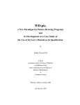
It has been observed that the pic language is well suited for drawing computer science technical document illustrations, such as flow charts and state diagrams. Thus, WD-pic is also intended
mainly for these kinds of diagrams. Figure 1.1 shows a flow diagram generated from the pic code
shown in Figure 1.2.
WD-pic runs on the Solaris UNIX environments with the JAVA runtime environment, version 1.3.1 or later.
document
WD-pic
troff
Figure 1.1: A flow diagram
1
typesetter
Introduction
2
ellipse "document"
arrow
box "WD-pic"
arrow
box "troff"
arrow
ellipse "typesetter"
Figure 1.2: pic code of Figure 1.1
1.2
First sample run
The picture in Figure 1.1 can be easily drawn with WD-pic. To start the program, run the
following command:
[lename]
lename is an optional parameter, specifying the name of an existing file to load as the internal
representation on start-up, or the name of a non-existent file that will receive the current internal
representation whenever Save of the File menu is requested.
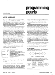
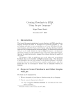
The screen layout of WD-pic is illustrated in Figure 1.3.
The following steps show one way to draw Figure 1.1. You will learn other ways to draw the
same picture in later sections.
wdpic
1. Left mouse click the ellipse button on the palette, and input " d o c u m e n t "1 from
the keyboard, without moving the mouse.
2. Left mouse click the arrow button.
3. Left mouse click the box button, and input " W D - p i c " from the keyboard, without
moving the mouse.
4. Left mouse click the arrow button.
1
White space is used to separate tokens; a blank token is denoted “ ”.
First sample run
3
Figure 1.3: Screen layout of WD-pic
Introduction
4
5. Left mouse click the box button, and input " t r o f f " from the keyboard without moving
the mouse.
6. Left mouse click the arrow button.
7. Left mouse click the ellipse button, and input " t y p e s e t t e r " from the keyboard
without moving the mouse.
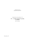
As you are doing the above operations, the internal representation shown in Figure 1.2 is
generated in the editing window and the picture shown in Figure 1.1 is drawn on the canvas, as
illustrated in Figure 1.4.
First sample run
5
Figure 1.4: First sample
Chapter 2
Conventions
2.1
User assumption
You, the user of WD-pic, are assumed to know the pic language well. If not, please refer to a
user’s manual of the pic program [2].
2.2
Notational conventions
The following text conventions are used in the manual:
Times Roman is used for normal text.
Times Italics is used for emphasis and new terms in normal text.
Times Bold is used for section names.
Helvetica is used for program names and file names except in command lines.
Helvetica Oblique is used for widget and key name variables.
Helvetica Bold is used for widget and key name constants.
Courier is used for internal representation contents.
6
Terms
7
Courier Oblique is used for variables of pic internal representation syntax.
Courier Bold is used for constants of pic internal representation syntax.
Computer Modern Sans Serif is used for command code and use case names.
Computer Modern Sans Serif Italics is used for variables of command syntax.
Computer Modern Sans Serif Bold is used for constants of command syntax.
<A + B >is used to specify the simultaneous combination of key A and key B .
MenuA!MenuItemB is used to specify the menu item MenuItemB in the menu MenuA.
2.3
Terms
The following terms are used throughout the manual:
WD-pic — the name of the program.
user — the person who uses WD-pic, addressed by “you”.
pic primitive — abbreviate as “primitive”, defined by the pic grammar, e.g., box, line,
arrow, circle, ellipse, arc, spline, and move.
pic object — abbreviate as “object”, a pic primitive together with its attributes.
pic token — abbreviate as “token”, a smallest semantically meaningful syntactic unit in
the pic language, e.g., box, line, arrow, circle, ellipse, arc, spline, move,
up, down, left, right, ;, :, ", and variable identifiers.
attribute — used to give more information about a primitive, consisting of a keyword,
perhaps followed by a value, e.g.,
Conventions
8
h(eigh)t expr ,
rad(ius) expr ,
up opt-expr ,
right opt-expr ,
from position,
at position,
by expr ,
dotted opt-expr ,
chop opt-expr ,
invis,
fill opt-expr ,
text-list,
wid(th) expr ,
diam(eter) expr ,
down opt-expr ,
left opt-expr ,
to position,
with corner ,
then,
dashed opt-expr ,
-> <- <->,
solid,
same,
expr .
In these attributes, the parenthesized text describes an optional full spelling of the containing token.
internal representation — abbreviate as “IR”, the text file containing the pic code corresponding to the picture drawn on the canvas.
session — an invocation of WD-pic.
edit window — abbreviate as “EW”, the window used to view and edit the IR.
external editor — your preferred text editor, not part of WD-pic, indicated to your operating system by setting a shell variable, e.g., setenv EDITOR vi.
canvas — used for displaying the picture corresponding to the IR.
palette — used for causing input to the IR, made up of the box, circle, ellipse, line,
arrow, spline, arc, ;, ", Constructs, Copy, Macros, Label, and Variables buttons,
and an attribute area, whose content changes to provide the attributes for the object that
was most recently inserted.
menu bar — used for operating and adjusting current session, made up of the File, Edit,
Tools, and Help menus.
Terms
9
menu item — a unit of a menu.
tool bar — shortcuts to some menu items, made up of the New, Open, Save, Copy,
Paste, Undo, Redo, Grid, and Help buttons.
screen layout — made up of a menu bar, a tool bar, a palette, a canvas and an EW, as shown
in Figure 1.3.
left mouse click — abbreviate as “LMC”, a left mouse click.
right mouse click — abbreviate as “RMC”, a right mouse click.
double click — two LMCs not more than 1 second apart.
current insertion point — abbreviate as “CIP”, the point in the IR in which the next object
will be inserted, indicated by the cursor on the canvas and the cursor in the EW; normally,
it is after the last inserted object.
the picture corresponding to an IR — the picture generated by pic when it interprets the
entire IR from start to end, regardless of where in the IR the CIP is.
current file name — a name for the file into which a Save would cause writing of the entire
IR.
basic interpretation cycle — abbreviate as “BIC”, the process starts with inputting into
the IR, and ends with the picture on the canvas being redrawn. For example, following
sequenced steps illustrate a BIC:
1. LMC a pic token on the palette.
2. The token is added to the IR.
3. The picture on the canvas is redrawn.
pop-up menu — a menu that is opened by a RMC on the canvas.
grid — a network of horizontal and vertical lines that provide coordinates for locating
points on the canvas; a grid is determined by Center , dX , and dY values, where Center
Conventions
10
is the origin; dX is the distance between any two adjacent horizontal lines; dY is the
distance of any two adjacent vertical lines.
grid point — a point in a grid at which a horizontal line and a vertical line cross.
gravity — used to control the restriction of positioning points; it has no effect on the IR.
gravity tightness radius — abbreviate as “tightness radius”, the radius of the area around a
grid point or an object corner around which gravity is effective.
approximate point — the point on the canvas that you LMCed.
indicated point — the point corresponding to an approximate point that is finally indicated
by WD-pic by use of gravity and inserted into the IR.
type xxx — type xxx from the keyboard without concern for the location of the cursor;
xxx is added to the IR at the CIP and is shown also in the EW.
type xxx into the EW — make sure the cursor is in the EW; type xxx from the keyboard;
xxx is added to the EW at the CIP.
type xxx into the external editor — make sure the cursor is in the external editor, type
xxx from the keyboard; xxx is added to the to-be-edited file, which is taken as the IR
after you save and quit the external editor.
type xxx into the yyy field of zzz dialog — make sure the cursor is in the yyy field of
zzz dialog; type xxx from the keyboard; xxx is added to the yyy field of zzz dialog.
2.4
Abbreviations
BIC — Basic Interpretation Cycle
CIP — Current Insertion Point
EW — Edit Window
GUI — Graphic User Interface
Basic user interface goals
11
IR — Internal Representation
LMC — Left Mouse Click
RMC — Right Mouse Click
WD — WYSIWYG Direct-manipulation
WYSIWYG — What You See Is What You Get
2.5
Basic user interface goals
Compared to the pic program, the major advantage of WD-pic is its GUI. This GUI gives you the
benefits of WYSIWYG and direction manipulation. Some other basic goals of the user interface
of WD-pic are the following:
All styles of input, i.e., by mouse or by keyboard, are fully interchangeable, without the
need to inform the application where its next input is coming from.
There is no need to move the mouse to the canvas or the EW except to explicitly and
directly identify a point or an object; therefore, the mouse movement is minimized.
The internal representation should be as much as possible what a human would write in
the pic language to achieve the picture shown on the canvas.
When inputting text that is expected and that has a definite end, there is no need to move
the mouse to a text window and to confirm at the end.
2.6
First sample redone
As mentioned in Section 1.2, there are always alternative ways to draw the same picture. Besides
using the palette as described in Section 1.2, you can also type the whole IR given in Figure 1.2
into the EW or with an external editor.
The following sequenced steps illustrate another way to draw Figure 1.1 strictly from the
keyboard:
Conventions
12
1. Type e l l i p s e. The ellipse token is added to the IR at the CIP. After you enter a
blank, an ellipse with default size is added at the CIP on the canvas.
2. Type " to start inputting text or you can LMC the " button on the palette. In either case, "
is added to the IR at the CIP.
3. Type d o c u m e n t. document is added to the IR at the CIP.
4. End the text input by typing " from the keyboard. After " is added to the IR, the ellipse
object is redrawn with text “document” in its center on the canvas.
5. Press the Enter key to finish inputting the ellipse object. A new line is started in the IR.
6. Type a r r o w. arrow is added to the IR at the CIP. After the Enter key is pressed, an
arrow with default size is added at the CIP on the canvas.
7. Type b o x " p i c ". box "pic" is added to the IR at the CIP. After the Enter key is
pressed, a box with “pic” at the center is added at the CIP on the canvas.
8. Type a r r o w. arrow is added to the IR at the CIP. After the Enter key is pressed, an
arrow with default size is added at the CIP on the canvas.
9. Type b o x " t r o f f ". box "troff" is added to the IR at the CIP. After the Enter
key is pressed, a box with “troff” at the center is added at the CIP on the canvas.
10. Type a r r o w. arrow is added to the IR at the CIP. After the Enter key is pressed, an
arrow with default size is added at the CIP on the canvas.
11. Type e l l i p s e " t y p e s e t t e r ". ellipse "typesetter" is added to the
IR at the CIP. After the Enter key is pressed, an ellipse with “typesetter” at the center is
added at the CIP on the canvas.
If you see the text in red in the EW after inputting ; or Enter key, you have made a syntax
error. Check your input in the EW, and correct it. If you see the text in red in the EW before
inputting ; or Enter key, the text could be right. WD-pic marks it red because the sentence is
not completed.
Using grid & gravity
13
Box1: box
box at Box1.c + (boxwid, boxht)
Figure 2.1: An example diagram
Figure 2.2: pic code of Figure 2.1
At this point, you should see the picture of Figure 1.1 drawn on the canvas while the pic code
of Figure 1.2 is in the EW, as illustrated in Figure 1.4.
In the following sections, you will learn how to change the attributes of the objects and how
to draw an object at a desired position.
2.7
Using grid & gravity
There are cases in which a specific position is desired. For instance, after having given an at,
from, or to token, you would then need to specify a position. A position could be a (x, y)
coordinate pair, or may be specified in other ways. For example, you might want to draw the
diagram shown in Figure 2.1.
This diagram can be generated from the pic code shown in Figure 2.2.
One way to draw Figure 2.1 and to get the IR shown in Figure 2.2 is to use the keyboard to
enter the text of Figure 2.2 into the IR. Another way is by direct manipulation.
Two key concepts of WD-pic are its grid and gravity. Their main purpose is to allow direct
manipulation placement of objects while getting (x, y) coordinates that would be written by a
human user when using pic in the batch mode. Gravity is used to map the approximate point that
you can achieve with a mouse to a corner of an existing object or to a grid point. When gravity
is off, the point you have LMCed, whatever its coordinates are as a pair of real numbers, is taken
as the indicated point.
The following steps show one way of using grid and gravity to draw the diagram:
Conventions
14
Figure 2.3: Grid Definition Dialog
Figure 2.4: Grid Box1C
1. LMC the box button. box is added to the IR at the CIP. A box with default size is drawn
on the canvas according to the IR.
2. LMC the Label button. Type B o x 1 and end the label input by typing :. Box1: is added
to the IR before box.
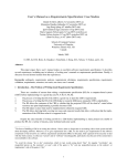
3. Select Tools!Define Grid from the menu bar. A Grid Definition dialog with fields
filled with default values, as illustrated in Figure 2.3, shows up.
4. Type Box1C into the Name field, Box1.c into the Center field, boxwid into the dX
field, and boxht into the dY field, as illustrated in Figure 2.4.
5. LMC the Activate Now button. A grid with name Box1C, center Box1.c, dX boxwid,
Using grid & gravity
15
Figure 2.5: A sample of using grid & gravity - I
and dY boxht is saved. The canvas is redrawn according to the current complete IR with
the activated grid Box1C superimposed, as illustrated in Figure 2.5.
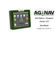
6. Select Tools!Set Gravity from the menu bar. A Gravity Settings dialog with fields
filled with default values, as illustrated in Figure 2.6, shows up.
7. Make sure that on and medium are selected, and gravitate to grid points and gravitate to pic corners are checked.
8. LMC the OK button.
9. LMC the box button from the palette. box is added to the IR at the CIP. The canvas is
redrawn from the current complete IR.
10. LMC the at button from the palette. at is added to the IR at the CIP.
11. Move the mouse to the canvas, and LMC the grid point just northeast of the box’s northeast
corner in Figure 2.7.
12. Box1.c + (boxwid, boxht) is added to the IR after the at at the CIP. The whole
picture is redrawn with the second box at the expected position, as shown in Figure 2.8.
Conventions
16
Figure 2.6: Gravity Setting Dialog
Figure 2.7: A sample of using grid & gravity - II
Figure 2.8: A sample of using grid & gravity - III
Organization of this manual
17
Grid and gravity are independent session concepts. They are used to help you work with the
objects on the canvas by direct manipulation. Thus the grid appears on the canvas, but not in the
IR. Details of grid and gravity setting are given in Sections 3.1.5 and 3.1.7.
2.8
Organization of this manual
The rest of the manual is organized mainly based on use cases. Chapter 3 describes the basic
use cases affecting both the session and the IR. Chapter 4 describes the advanced features of the
program. What to do if you have trouble and tips on how to use the program better are given in
Chapter 5. Chapter 6 gives the limitations of the current version of WD-pic.
Chapter 3
Basic Use Cases
A use case is classified according to its effect, whether the effect is on the session or on the IR.
All the manipulations in a use case are based on the assumption that the program is running,
unless otherwise specified.
There are some basic dialog manipulations that happen in many use cases:
The Cancel button and the OK button are used almost in every dialog. LMCing the
Cancel button closes the dialog without having any effect. LMCing the OK button closes
the dialog while causing the intended effect of the dialog.
The Default button is given in dialogs in which values are to be input into fields. LMCing
this button fills each field with the appropriate default value according to the purpose of
the dialog.
The Reset button is given in dialogs in which values are to be input into fields. LMCing
this button clears every field. Then you can start filling the fields again.
3.1
Affecting the session
3.1.1
Basic file manipulations
There are four basic file manipulations: New, Open, Save, and Save
18
as.
Affecting the session
19
Figure 3.1: Open Dialog
New: create a new IR. There are three ways:
– With the menu bar: select File!New from the menu bar.
– With the shortcut key: type <Ctrl+N>.
– With the tool bar: LMC the New button in the tool bar.
The IR is set to empty, and Untitled is established as the current file name.
Open: open an existing file, which is assumed to contain pic code.
– With the menu bar: select File!Open from the menu bar or select a recently opened
files from File!Recent Files.
– With the shortcut key: type <Ctrl+O>.
– With the tool bar: LMC the Open button in the tool bar.
An Open dialog, as illustrated in Figure 3.1, shows up on the screen. In any of the standard
ways, indicate the name of the file you want to open. Then LMC the OK button.
The indicated file name is established as the current file name. The content of the named
file is established as the IR and shows up in the EW. Finally, the picture corresponding to
Basic Use Cases
20
the complete IR is drawn on the canvas.
Save: save the current complete IR.
– With the menu bar: select File!Save from the menu bar.
– With the shortcut key: type <Ctrl+S>.
– With the tool bar: LMC the Save button in the tool bar.
Normally Save is done when a file name is established. If there is no current file name
established, a Save As dialog, as illustrated in Figure 3.2, shows up. In any of the standard
ways, indicate a file name. Then LMC the OK button. The file name is taken as the current
file name. In any case, the current complete IR is saved in the file named by the current
file name.
Save as: establish a new current file name and save the current complete IR in the named
file.
– With the menu bar: select File!Save As from the menu bar.
A Save As dialog, as shown in Figure 3.2, pops up. In any of the standard ways, indicate
a file name. Then LMC the OK button.
The indicated file name is taken as the current file name. Finally, the current complete IR
is saved in the file named by the current file name.
3.1.2
Standard Edit menu items
The Edit menu has the following standard items:
Undo - to undo the last action in the edit window,
Redo - to redo the last action in the edit window,
Copy - to copy the selected content in the edit window to the clipboard,
Paste - to paste the content in the clipboard to the edit window,
Affecting the session
21
Figure 3.2: Save As Dialog
Cut - to cut the selected content in the edit window,
Undo and Redo are not always available. Undo is enabled only when there has been some
change made to the IR, e.g., adding, deleting text. Redo is enabled when Undo has been done.
Please note that these standard items only work with the EW. You will see the use of other
items in the Edit menu, such as Change Attribute, Reset Font, Set CIP, and Run External
Editor in later sections.
3.1.3
Using external editor on the IR
Besides using the EW to review and edit the IR, you can also specify any external text editor that
is accessible from your system to work on the IR. The following steps show you how to set and
work with such an external editor:
1. Set the external editor. Two ways to do that are:
Before starting WD-pic, run the following command or whatever command your host
system uses to set shell variables:
setenv EDITOR editorname or set EDITOR = editorname,
where editorname is the name of the editor that you prefer to use.
Basic Use Cases
22
Figure 3.3: Set External Editor Dialog
If you start WD-pic without having run the above command, choose Tool!Set
External Editor from the menu bar. A Set External Editor dialog, as illustrated
in Figure 3.3, pops up. Enter the name of your preferred text editor. Then LMC the
OK button.
2. Run the external editor:
With the menu bar: choose Editor!Run External Editor from the menu bar.
With the shortcut key: type <Ctrl+R>.
The external editor launches. The current complete IR is copied as the file to be edited by
the external editor.
3. Edit the to-be-edited file as you wish.
4. Save and quit the external editor, causing the last version of the to-be-edited file to be taken
as the IR.
The saved IR is copied into the EW. The picture corresponding to the complete IR is drawn on
the canvas.
Note that any time you need to modify the IR, you can do it either by direct manipulation
editing of the EW or by use of an external editor. However, the advantage of using an external editor is that you are able to invoke a specialized editor with powerful commands or your
favourite editor whose commands are most familiar to you.
Affecting the session
23
Figure 3.4: Sample of selected object, the box on the left
Figure 3.5: Grid Definition Dialog
3.1.4
Selecting an object
If you want to select an existing object, you can either LMC or RMC the object on the canvas
that you want to select.
The indicated object is highlighted in a different color on the canvas, as illustrated in Figure
3.4. Also the related primitive in the EW of the object is highlighted in the same color.
3.1.5
Defining grid
In WD-pic, a picture could have several grids with different settings. Each grid is saved with a
unique name given by you or the program by default. To define a new gird, choose Tools!Define
Grid from the menu bar. A Grid Definition dialog, as illustrated in Figure 3.5, shows up, initialized to the default values.
The default values for the fields are:
Name: NewGrid
Basic Use Cases
24
Center: (0,0)
dX: movewid
dY: moveht
If you do not like the name NewGrid for the new grid, input a new grid name n of your
choice by typing into the Name field. Indicate the center of the grid by typing into the Center
field or selecting from the field’s pop-up list. The center must be some point, and could be
specified by a symbolic expression, such as Box1.c, or by a constant, such as (0,0). Define
the dX and the dY field values by typing into the fields or selecting from the fields’ pop-up lists.
After you are done, LMC the Save button. The grid setting is saved with the given name n.
You can activate the saved grid anytime later by giving its name, n. If you want to activate grid
n right now, LMC the Activate Now button. The just defined grid n is activated. The canvas
is redrawn according to the current complete IR with grid n superimposed. If you do not see
the grid superimposed on the canvas, you have made an error when defining the grid. Check the
status bar for further information and re-define the grid. Section 3.1.6 describes how the grid is
determined from the data of the grid setting.
To modify a previously defined grid, choose its name from the field’s pop-up list. Make the
changes. Then LMC the Save button.
3.1.6
Activating grid
If you want to activate a previously defined grid, choose Tools!Activate Grid from the menu
bar, or RMC the canvas and choose Activate Grid from the pop-up menu. If there is not a
previously saved grid, a warning dialog shows up. You are asked to define a grid. Otherwise, a
Grid Activation dialog, as illustrated in Figure 3.6, shows up. Select the name of the grid that
you want to activate from the pop-up list of the Name field. Then LMC the OK button. The
named grid is activated. The canvas is redrawn according to the current complete IR with the
activated grid superimposed. This grid is determined by the previously defined Center , dX , and
dY values in the Grid Setting dialog. Center is the origin. A horizontal line and a vertical line
cross at this origin. The distance between any two adjacent horizontal lines of the grid is dX ,
and the distance between any two adjacent vertical lines of the gird is dY .
Affecting the session
25
Figure 3.6: Grid Activation Dialog
3.1.7
Setting gravity
To set the gravity, choose Tools!Set Gravity from the menu bar. Or RMC the canvas and
choose Set Gravity from the pop-up menu. A Gravity Setting dialog, as illustrated in Figure
3.7, shows up.
Click On or Off to turn the gravity on or off. Whenever gravity is off, whatever (x, y)
coordinates are indicated by the mouse is taken as the indicated point. Gravity has three tightness
radii: coarse at 1/4 inch, medium at 1/8 inch and fine at 1/16 inch. Choose any one. Select
gravitate to grid points and gravitate to pic corners to cause the grid points and corners
of existing objects to be indicated. Whenever the gravity is on, and the distance between the
approximate point and a grid point or a corner is within gravity’s tightness radius of the grid
point or the corner, the grid point or the corner is indicated.
If a picture is scaled, the tightness radii are divided by the scale value at the CIP.
3.1.8
Setting the current insertion point
Normally, the CIP is just after the last inserted object, where the cursors are in the EW and on
the canvas. There are two ways to change the CIP:
Direct manipulation:
– With the pop-up menu:
Basic Use Cases
26
Figure 3.7: Gravity Setting Dialog
1. Point the mouse at the object whose definition in the IR is desired to position the
CIP.
2. RMC the object, choose Set CIP from the pop-up menu.
– With the menu bar:
1. Select the object by LMCing it.
2. Choose Edit!Set CIP from the menu bar.
The cursor in the EW is moved to the new insertion point. The cursor on the canvas is
moved too.
In the EW: Move the cursor to the pic token after which you want the CIP to be positioned.
The cursor on the canvas is moved too.
Affecting the IR
3.2
Affecting the IR
3.2.1
Inserting an object
27
There are two ways to insert an object at the CIP:
With the palette: LMC the desired pic token on the palette.
With the keyboard: type the related pic primitive and signal the end of the object either by
typing a ; token, or by pressing the Enter key.
For example, if you want to draw a box, you can either LMC the box button on the palette,
or type b o x and press the Enter key from the keyboard. The pic code box is added to the IR
at the CIP. The canvas is redrawn according to the complete IR. The result is that a box of default
size is drawn after the previous CIP and the CIP follows the just added box.
3.2.2
Adjusting attributes during insertion
There are several ways to change the attributes of an object during insertion:
Assume a primitive has just been inserted into the IR.
With the palette: All possible attributes of the primitive are shown in the attributes area of
the palette as buttons. Figure 3.8 illustrates the palette after a box has been added to the
IR. There are several types of buttons in the attributes area.
1. an independent button, e.g., fill and invis. LMCing one of these buttons will add its
token, e.g., fill and invis to the IR at the CIP.
2. a button with a value field, e.g., wid, ht and at. LMCing one of these buttons causes
the addition of both its token and the value shown in the field to the IR. You can
change a value by typing into its field. If a value field is empty, only the token is added
to the IR. In this last case, WD-pic will be expecting that you will provide the required
value by another means, e.g., typing, typing into the EW, or direct manipulation.
3. a button in a set of buttons connected with ks, e.g., solid k dashed k dotted. You
can LMC only one of them to add its token to the IR.
Basic Use Cases
28
Figure 3.8: box Attributes
To change the attributes of the object, change the values in the fields if necessary and LMC
the related buttons in the attributes area.
With the keyboard: Type the attributes at the CIP. For the example, type w i d = expr .
End inputting the object by typing ; or pressing the Enter key. wid=expr ; is added to
the IR at the CIP.
In either case, the picture on the canvas is redrawn according to the current complete IR.
Affecting the IR
29
Figure 3.9: Label Dialog
3.2.3
Indicating x, y coordinates
There are two ways to indicate x, y coordinates, direct manipulation and textually.
Direct manipulation: If you want to specify a point by direct manipulation, e.g., after an
at, from, or to token, you may wish to make sure the grid and gravity are set properly.
Otherwise the exact point the mouse is at is taken as the indicated point and this will need
to be expressed as a pair of real numbers, (x, y). As mentioned in Section 3.1.7, when
gravity is on, a grid point or a corner of an existing object could be taken as the indicated
point.
Move the mouse close to the point that you want to indicate on the canvas. Its exact (x, y)
coordinates of the point are shown at the right side of the status bar. LMC the point. There
are three cases:
– Corner: If the indicated point is a corner of an object, the expression of this corner
consisting of the object’s label and the corner’s designation, e.g., n, e, or ne, is
added to the EW. If the object has no label, a Label dialog, as illustrated in Figure
3.9, shows up. Input a label for the object in the field. Then LMC the OK button.
– Grid point: If the indicated point is a grid point, a symbolic expression for the indicated point, as specified below, is added to the IR at the CIP:
Center + (n * dX, m * dY)
Basic Use Cases
30
Figure 3.10: Indicate points with grid & gravity
where |n| is one less than the number of horizontal lines from the origin to the indicated point inclusive, and n = -|n| if the indicated point is to the left of Center ;
|m| is one less than the number of vertical lines from the origin to the indicated point
inclusive, and m = -|m| if the indicated point is below Center . Center , dX and dY
are the values of Center , dX , dY of the current activated grid, respectively.
For example, assume the current activated grid is defined as: Center = Box1.ne,
dX = boxwid, dY = boxht. The symbolic expression of the point marked “+”
in Figure 3.10 is :
Box1.ne + (2*boxwid, boxht).
This expression is added to the IR at the CIP.
– Arbitrary other (x, y) point: If the LMCed point is not any corner or grid point, the
coordinates of the point are added to the IR at the CIP.
When gravity is off, the exact point the mouse is at is taken as the indicated point.
Textually: Type position, where position is a pic expression for the position of the
desired point. position is added to the IR at the CIP.
3.2.4
Adding text
In pic, text can be either an attribute of any pic primitive except move, or a standalone object.
Each line of text is a separate quoted string.
Affecting the IR
31
Adding text as an attribute is the same as adjusting other attributes. Assume that you have
just inserted an object, such as a box, into the IR at the CIP.
– With the palette:
1. LMC the " button. " is added to the IR.
2. Type the text that you want to attach to the object, and end by typing ". The
typed text followed by " is added to the IR at the CIP as you type.
– With the keyboard:
1. Type ", and " is added to the IR.
2. Type the text you want to attach to the object, and end by typing ". The typed
text followed by " is added to the IR at the CIP as you type.
A way to get multiple text items associated with an object, each in a separate line centered
inside the object is to repeat Steps 1 through 2 for each text item.
Adding text as a standalone object is the same as adding text as an attribute, except that the
quoted text is not following any other object.
Chapter 4
Advanced Features
4.1
4.1.1
Affecting the session
Setting font and size of text
If you want to change the font format of some text, even as small as one character, LMC one end
of the text. Drag the mouse to highlight the text that you want to change. Choose Tools!Font
from the menu bar. A Font dialog, as illustrated in Figure 4.1, shows up. In a standard way,
select your preferred font format including style and size, then LMC the OK button.
The selected text on the canvas is changed to the selected font format. As there is no font
information in the pic language, the IR is not changed. Consequently, the setting of the font and
size affects only the appearance of the text in the canvas for the current session.
In pic, text in quotes is passed verbatim to troff which does the font and size changes according to troff font and size change commands in the quoted text. So pic itself does nothing with
fonts and sizes. To be able to see what the result would look like when printed, use these font
and size settings session commands to make the font and size of the displayed text be what troff
thinks it is. You can make the troff commands themselves invisible so that they are not displayed.
For instance, assuming that the current canvas font is Times Roman, to get the result of a box
with “Hello” in Helvetica, size 8, follow the steps:
1. Insert box "\fH\s8Hello\s0\fP" into the IR. The canvas is drawn with a box centered with text “\fH\s8Hello\s0\fP”, as illustrated in Figure 4.2.
32
Affecting the session
33
Figure 4.1: Font Dialog
2. Select “\fH\s8” on the canvas, choose Tools!Font from the menu bar, select Invisible
in the Font dialog, or set the size to 0.
3. LMC the OK button. “\fH\s8” is made invisible and zero width on the canvas.
4. Select “\s0\fP” on the canvas, choose Tools!Font from the menu bar, select Invisible
in the Font dialog, or set the size to 0.
5. LMC the OK button. “\s0\fP” is made invisible and zero width on the canvas.
6. Select “Hello” on the canvas, choose Tools!Font from the menu bar and set the font to
Helvetica or Arial, size 8.
7. LMC the OK button. You see “Hello” in Helvetica size 8 centered in the box on the canvas,
as illustrated in Figure 4.3.
Once any text is set to invisible, you cannot select it on the canvas. To see the invisible text
on the canvas, RMC the object which the text is an attribute, choose Reset Font. Alternatively,
Advanced Features
34
Figure 4.2: A sample of setting font, before
Figure 4.3: A sample of setting font, after
you can select the object by LMCing it. Then choose Reset Font from Edit menu. In either
case, the font of the selected object is set back to the system default font.
4.1.2
Preferences
Choose Tools!Preferences from menu bar. A Preferences dialog, as illustrated in Figure
4.4, shows up. You can set your preferred values for the attributes of box, circle, ellipse,
line, arrow, arc, and spline. After you are done, LMC the OK button.
The changes you make will affect the new inserted objects by using the palette from now
on, until the next time you change the preferences again. By this means, whenever you add
a primitive into the IR by LMCing the buttons on the palette, the preferred attributes of that
primitive that you set in the Preferences dialog are added to the primitive automatically as
they are added to the IR. For instance, if you change the line style of box to dotted, then
dotted will be added to the IR to each box that is inserted into the IR by LMCing the box
button on the palette after the preference is changed.
4.2
4.2.1
Affecting the IR
Changing values of variables
The pic program has 20 variables, e.g., boxwid and boxht. There are two ways to change any
of these values:
With the palette:
Affecting the IR
35
Figure 4.4: Preferences Dialog
1. LMC the Variables button on the palette. A Variables dialog, as illustrated in
Figure 4.5, shows up.
2. Choose the variable var that you want to change from the field’s pop-up list. var ’s
value at the CIP and the default value show up.
3. Type a valid pic expression expr into the New Value field.
4. LMC the OK button.
With the keyboard: type assignment for the variable var that you want to change, e.g.,
var =expr .
An assignment statement for the changed variable, e.g., var =expr , is added to the IR at the
CIP. The canvas is redrawn according to the current complete IR.
4.2.2
Changing attributes of an existing object
You can change the attributes of an existing object with the palette during insertion, as described
in Section 3.2.2, or you can change the attributes later in any of the following ways:
Advanced Features
36
Figure 4.5: Variables Dialog
Direct manipulation:
– With the palette:
1. Select the object, as described in Section 3.1.4. The available attribute tokens of
the selected object show up in the attributes area on the palette.
2. Make the changes.
3. LMC the attribute buttons to change the values. The modifications are saved into
the IR.
– With the pop-up menu:
1. RMC the object.
2. Choose Change Attribute from the pop-up menu. An Object Attributes
dialog shows up based on what kind of object is selected. Figure 4.6 illustrates a
Box Attributes dialog.
3. Make the changes.
4. LMC the OK button. The modifications are saved into the IR.
With the keyboard: Find the object in the EW whose attributes you want to change. Add
or change the values of attributes.
Affecting the IR
37
Figure 4.6: Box Attributes Dialog
Advanced Features
38
Figure 4.7: Constructs Dialog - Loop
In any case, the picture on the canvas is redrawn from the complete IR.
4.2.3
Constructs
Loops
With the palette:
1. LMC the Constructs button on the palette. A Constructs dialog, as illustrated in
Figure 4.7, shows up.
2. If the Loop tab is not in front of the other tabs, LMC the Loop tab.
3. Fill in the parts of the for statement. The parts are for, to, by, and do.
Affecting the IR
39
4. LMC the OK button.
With the keyboard: Type f o r
anything } at the CIP.
expr1
to
expr2
by
expr3
do
{
In any case, for expr1 to expr2 by expr3 do { anything } is added to the IR at the
CIP. The picture on the canvas is redrawn from the complete IR.
Conditionals
With the palette:
1. LMC the Constructs button on the palette. A Constructs dialog, as illustrated in
Figure 4.7, shows up.
2. If the Conditional tab is not in front of the other tabs, LMC the Conditional tab.
An empty if statement shows up, as illustrated in Figure 4.8.
3. Fill in the parts of the if statement. The parts are if, then and else.
4. LMC the OK button.
With the keyboard: Type i f
anything2 } at the CIP.
expression
then
{ anything1 }
else
{
In any case, if expression then { anything1 } else { anything2 } is added to
the IR at the CIP. The picture on the canvas is redrawn from the complete IR.
Blocks
With the palette:
1. LMC the Constructs button on the palette. A Constructs dialog, as illustrated in
Figure 4.7, shows up.
2. If the Block tab is not in front of the other tabs, LMC the Block tab. An empty
block statement shows up, as illustrated in Figure 4.9.
Advanced Features
40
Figure 4.8: Constructs Dialog - Conditional
Affecting the IR
41
Figure 4.9: Constructs Dialog - Block
Advanced Features
42
Figure 4.10: Macros Dialog - Define
3. Fill in the parts of the block statement. The parts are block name and body.
4. LMC the OK button.
With the keyboard: Type blockname : { anything } at the CIP.
In any case, blockname : { anything } is added to the IR at the CIP. The picture on the
canvas is redrawn from the complete IR.
4.2.4
Macros
Define
With the palette:
1. LMC the Macros button on the palette. A Macros dialog, as illustrated in Figure
4.10, shows up.
2. If the Define tab is not in front of the other tabs, LMC the Define tab.
3. Fill in the parts of the define statement. The parts are macro name and replacement
text.
4. LMC the OK button.
Affecting the IR
43
Figure 4.11: Macros Dialog - Undefine
With the keyboard: Type d e f i n e
name
{ replacement text } at the CIP.
In any case, define name { replacement text } is added to the IR at the CIP. The
picture on the canvas is redrawn from the complete IR.
Undefine
With the palette:
1. LMC the Macros button on the palette. A Macros dialog, as illustrated in Figure
4.10, shows up.
2. If the Undefine tab is not shown in front of other tabs, LMC the Undefine tab. An
empty undef statement, as illustrated in Figure 4.11, shows up.
3. Fill in the macro name that you want to undefine in the undef statement.
4. LMC the OK button.
With the keyboard: Type u n d e f
macro-name at the CIP.
In any case, undef macro-name is added to the IR at the CIP. The picture on the canvas
is redrawn from the complete IR.
Advanced Features
44
Figure 4.12: File Copy Dialog - Copy
4.2.5
File copy
Copy
With the palette:
1. LMC the File Copy button on the palette. A File Copy dialog, as illustrated in
Figure 4.12, shows up.
2. If the Copy tab is not in front of the other tabs, LMC the Copy tab.
3. Fill in the name of the file that you want to copy in the copy statement.
4. LMC the OK button.
With the keyboard: Type c o p y
" filename " at the CIP.
In any case, copy "filename" is added to the IR at the CIP. The picture on the canvas is
redrawn from the complete IR.
Copy Through
With the palette:
1. LMC the File Copy button on the palette. A File Copy dialog, as illustrated in
Figure 4.12, shows up.
Affecting the IR
45
Figure 4.13: File Copy Dialog - Copy Through
2. If the Copy Through tab is not in front of the other tabs, LMC the Copy Through
tab. An empty copy thru statement is shown up, as illustrated in Figure 4.13.
3. Fill in the parts of the copy thru statement. The parts are file name and macro
name or macro replacement text.
4. LMC the OK button.
With the keyboard: Type c o p y " file " t h r u macro-name or c o p y
file " t h r u { macro replacement text } at the CIP.
"
In any case, copy "file" thru macro-name or copy "file" thru { macro replacement text } is added to the IR at the CIP. The picture on the canvas is redrawn from
the complete IR.
sh
With the palette:
1. LMC the File Copy button on the palette. A File Copy dialog, as illustrated in
Figure 4.12, shows up.
2. If the sh tab is not in front of the other tabs, LMC the sh tab. An empty sh statement
is shown up, as illustrated in Figure 4.14.
Advanced Features
46
Figure 4.14: File Copy Dialog - sh
3. Fill in the body of the sh statement.
4. LMC the OK button.
With the keyboard: Type s h
{ anything } at the CIP.
In any case, sh { anything } is added to the IR at the CIP. The picture on the canvas is redrawn
from the complete IR.
4.2.6
Labelling
With the palette:
1. LMC the Label button on the palette. The CIP moves to the beginning of the beingedited object.
2. Type the name of the label, beginning with an uppercase letter.
3. Type : to signal the end of label name. The CIP moves back to wherever it is before
LMCing the Label button.
With the keyboard:
1. Find the object in the EW to which you want to add a label and set the CIP to the
beginning of the object.
Affecting the IR
2. Type the name of the label, beginning with an uppercase letter.
3. Type : to signal the end of the label name.
In either case, the label is added to the being-edited object in the IR.
47
Chapter 5
Trouble Shooting & Tips
5.1
Trouble shooting
Choose Help!Content from the menu bar or LMC the Help button on the tool bar. You can
also press the F1 key on the keyboard.
5.2
Tips
Construct a picture sequentially.
Work in the EW, as it helps to check the syntax error while typing.
Work carefully with insertion if direction is changed.
48
Chapter 6
Limitations
The sizes and positions of objects cannot be changed by direct mouse manipulations.
Copy, paste, cut, undo, and redo work only with the EW, not the canvas.
One cannot do search and replace in the EW.
Font information of the text is not saved.
One cannot directly manipulate constructs, e.g., for, if, and block, on the canvas.
One cannot output pictures in a standard graph format, e.g., gif and png, or print from
WD-pic. You have to feed the saved pic file to pic or to another program that is capable of
dealing with pic input.
49
Bibliography
[1] Narain Gehani. Document Formatting and Typesetting on the Unix System second edition.
Silicon Press, Summit, NJ, 1987.
[2] Brian W. Kernighan. PIC - A Graphics Languages for Typesetting. Bell Laboratories,
Computer Science Technical Report No.116, December 1984.
[3] B. Srinivasan. Unix Document Processing and Typesetting. World Scientific, Singapore,
New Jersey, London, 1993.
50