1
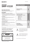
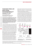
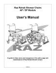
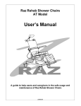
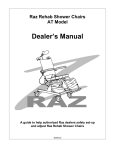
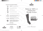
I N S TA L L AT I O N / U S E R S M A N UA L
!
IMPORTANT: The installation and set up instructions should
be carried out by a qualified technician.
IMPORTANT: It is important to refer to the wheelchair owner’s
manual for additional safety information related
to the safe operation of the wheelchair.
TABLE OF CONTENTS
1 Mounting hardware contents . . . . . . . . . . . . . . . . . . . . . . . . . . . 3
2 Tools required. . . . . . . . . . . . . . . . . . . . . . . . . . . . . . . . . . . . . . . 3
3 Important installation information. . . . . . . . . . . . . . . . . . . . . . . . 4
4 Installation Instructions. . . . . . . . . . . . . . . . . . . . . . . . . . . . . . . . 6
5 Removing the backrest. . . . . . . . . . . . . . . . . . . . . . . . . . . . . . . 10
6 Removing the backrest cover for washing . . . . . . . . . . . . . . . . 10
7 Installing pelvic/lumbar or lateral supports. . . . . . . . . . . . . . . . 11
8 Installing the head/neck support hardware . . . . . . . . . . . . . . . 11
Complies with:
-ISO 16840-4 Wheelchair Seating - part 4: Seating Systems for use in motor vehicles.
-RESNA WC-4:2012 Section 20: Seating Systems for use in motor vehicles.
It is recompensed that a headrest be used when the back rest is used for transport
in a motor vehicle.
1422791 Ontario Ltd
Dynamic Health Care Solutions
753011 2nd Line, Mono ON L9W 2Z2, Canada
+519-942-8441
EC
REP
|
www.DynamicHCS.com
Advena Ltd. 33 Bridge St, Hereford HR4 9DQ, UK
1 Mounting Hardware Contents
2 - Cane clamps
2 - Backrest mounting plates with pins
6 - Back angle and depth adjustment screws
2 - Back angle and depth locking plates
4 - Back cane clamp screws
4 - Back cane clamp nuts
2 - Back cane clamp nut retainer plates
13
8
10
6
3
14
11
9
12
5
1
PARTS PER CLAMP
ITEM
PART #
Item No.
1
2
3
4
5
6
7
8
9
10
11
1
2
3
4
5
6
7
8
9
10
11
12
13
14
NIB-0509
NIB-0276
NIB-0501
NIB-0505
NIB-0504
IB-0048
NIB-0506
NIB-0507
IB-0193
NIB-0514
NIB-0515
NIB-0510
NIB-0512
NIB-0541
DESCRIPTION
PartNo.
NIB-0509
NIB-0276
NIB-0501
NIB-0505
NIB-0504
IB-0048
NIB-0506
NIB-0507
IB-0193
NIB-0514
NIB-0515
4
7
2
QTY
Description
Qty.
CLAMP - INNER
1
SPLIT CLAMP - OUTER
2
HEX SOCKET SET SCREW M6X6
1
M6X30 SBHCS
2
HJN M6
2
NUT RETAINER
PLATERequired 1
2 Tools
M6X20 SBHCS
3
Wrenches – 10mm – 13mm
CLAMP PLATE
1
keys –WASHER
4mm (5/32") – 3mm
5/16" INTERNALAllen
TOOTHED
2
ATTACHING POST-THREADED
1
ATTACHING POST
1
clamp - inner
split clamp - outer
hex socket set screw M6X6
M6X30 SBHCS
HJN M6
nut retainer plate
M6X20 SBHCS
clamp plate
5/16” internal toothed washer
attaching post-threaded
attaching post
hex socket button head M6X10
M8 HLN thin
universal back mounting bracket
1
2
1
2
2
1
3
1
2
1
1
2
1
1
3
3 Important Information: Follow Before Installation
WEIGHT CAPACITY: The weight capacity of the nxt Back is 300lbs – 136kg
Please note that the Quickfit mounting hardware on the nxt Back are preassembled with the cane clamp in the rear most mounting position to maximize
seat depth of the wheelchair – see Fig. 1 below.
The configuration can be changed by orienting the Quickfit cane clamp forward,
providing a forward mounting position. See figure 2 below.
Note: The Quickfit mounting hardware provides 2.5"–6.4cm (3.5"–8.9cm on
VC Back) of depth adjustment, in front of and behind the back canes.
To set the Quickfit mounting hardware in the forward most position:
• Remove the cane clamp from the mounting plate
• Rotate the cane clamp 180° and re-attach it to the mounting plate
• Install clamp as shown in Fig. 2
Fig. 1: Quickfit clamp in rearward most position.
1
32"
1
22"
Fig. 2: Quickfit clamp in forward most position.
1
32"
1
22"
Please Note: Setting the desired position of the nxt Back may compromise
the stability of the wheelchair.
Be aware that the forward and aft position for the backrest will change the user’s
centre of gravity within the wheelchair. A back set in the most rearward position
can significantly reduce the rearward stability of the wheelchair. In contrast, a
more forward back position may reduce the wheelchair’s forward stability.
4
3 Important Information: Read Before Installation
The Quickfit mounting hardware can
accommodate different size back canes.
3/4"–19mm 7/8"–22mm and 1"–25mm back
canes can be accommodated without inserts,
see Fig. 3.
DYNAMIC HEALTH CARE
SOLUTIONS
Fig. 3:
Back Rest attachment post metric extension kit PN: NIB-07
POST SPACER ATTACHMENT INSTALLATION
ws Back
Resta to
fit up
to a
2" wider
wheelchair
than
Backhead
Restscrews.
optimal width.
1. Using
4mm
(5/32”
) Allen
Wrench
remove the
2 button
allows 16" wide nxt Back Rest to fit 18" wide chair. Standard posts allow for
Install the spacer
between 4the
lock washer
and attachment
wider2.
wheelchair.
Kit includes
spacers
PN: NIB-0260
and 4post.
screws PN: NIB-0709
3. Install the new button head screw and tighten securely.
4. Do this to both attachment posts on the left and right side of back.
UP DIRECTION
Up Direction
Spacer NIB-0260
Spacer
NIB-0260
Screw NIB-0709
Screw
NIB-0709
Use these
this hole
extra
seat
Use
holesif with
the
depth
VC
backisorneeded.
if extra seat
depth is needed.
Left Side Assembly Shown
LEFT SIDE ASSEMBLY SHOWN
5
4
nxt Back Installation Instructions
WARNING:DO NOT substitute hardware provided.
Use only high strength hardware provided.
1. Remove wheelchair back upholstery if applicable
2. Establish the desired mounting plate configuration
for the user as described in section 3.
3. Loosen the two cane clamp screws and mount Quickfit bracket on the back canes.
4. Position the cane clamp at the height desired and tighten screws enough to
hold it in place. Full tightening can be done when back is installed and final
adjustments have been done.
5. The Multi-clamp cane mounting hardware can be installed where a smaller size
tube is inserted into a larger tube (ie 3/4"–19mm inside a 1"–25mm tube). First
tighten clamp around larger tube, then tighten set screw using a 5/32" Allen
wrench until they touch the smaller diameter tube, holding the tube straight,
then tighten clamp around smaller tube. See Fig. 4 below.
6. Measure the height of the Quickfit clamp assembly from a fixed position on
the wheelchair and install the second at the same desired height. Further,
make sure the cane clamp mounting plates are mounted parallel with each
other. See Fig. 5 below.
7. All HA (Height Adjustable) Backs can be infinitely adjusted from 16"–40.6cm
to 20"–50.8cm. Loosen the three cap screws with a 4mm Allen wrench on the
rear of the backrest, set the backrest to the desired height and tighten the
lock nuts into place. When the HA Back is in its lowest position, tuck
the excess padding behind the seat cushion. See Fig. 6 below.
M6 Set Screw
Fig. 4: MultiClamp/Set Screws
6
Fig. 5: Cane clamps must be
installed at the same height
and parallel to each other
Fig. 6: Loosen 3 cap screws
to adjust back height
4
nxt Back Installation Instructions
6. To install the backrest on the mounting plates:
Step 1. Insert the top of the backrest slot onto the top adjustment pins
Step 2. Rotate the lower section of the backrest rearward to lock it into the
locking latch to secure the backrest in place.
Step 1
Step 2
Step 3
7. To ensure the backrest is properly fitted you may need to adjust the
lock nuts on the top mounting pins. Due to variances between different
wheelchair manufacturers, the lock nuts are adjustable. The lock nuts
can be adjusted to allow installation onto a wheelchair which is 1"–25mm
wider than the actual backrest. Mounting pin spacers allow the nxt Back to
fit 3 sizes of chairs, (ie a 16"–40.6cm back can
be mounted on a 16"–40.6cm, 17" – 43.8cm
or 18"–45.7cm wide wheelchair). Remove the
existing pins, add the spacer in between the
clamp plate and the pin and tighten into place
with longer Allen screws provided , as shown in
section 3. Mounting pin spacers are available
on request when ordering the nxt Back.
Tighten lock nut allowing 1/8"–3.2mm
of space between inner nut and back slot
7
4
nxt Back Installation Instructions
8. To adjust the lock nuts on the mounting pins refer to the instructions below.
a. Secure the backrest in place on the wheelchair and determine the
amount of adjustment required for each lock nut. See diagram below.
b. Remove the backrest from the wheelchair and use a 13mm wrench to
adjust the lock nuts.
c. To adjust the lock nuts, turn the nuts clockwise to shorten and counter
clockwise to lengthen. For easy removal and installation of the
backrest leave a minimum of 1/8"–3.2mm gap between the backrest
mounting slot and the lock nut.
Adjustment for Back Width
1
8 " MAXIMUM
8
Set adjustment pin nut
up to within 1/8"–3.2mm
of the backrest slot
4
9.
nxt Back Installation Instructions
Make sure that the overall fit and alignment of the back is correct, if not
make adjustments as required.
10. Secure the cane clamp screws onto each back cane.
11. Setting the best depth and recline settings it is best done with the client seated
in the wheelchair. While the client is seated and supported in the wheelchair,
loosen the depth screws on the mounting plate and set to the desired
position. Tighten all screws to lock the backrest in position. The backrest can
be mounted asymmetrically, so be sure that it is symmetrical if desired.
Depth/Recline screws
The notches on the plate are to
be used as a reference guide
for symmetrical adjustment on
the right and left sides.
9
5 Removing the BackresT
To remove the backrest from the wheelchair
Step 1. Lift on the one hand release lever to release the latches,
push the bottom of the back forward.
Step 2. Lift the backrest off the upper pins to remove completely.
6 Removing the Cover for Washing & Care
1. Release the upholstery tab from the top rear of the backrest.
2. Release the hook Velcro from the bottom of the backrest shell,
and remove the pad.
3. For light cleaning of the backrest fabric may be wiped down with a damp cloth.
4. Follow laundering instructions provided with the cover.
Release upholstery tab
10
Undo velcro closure & remove foam pad before washing outer
cover
7 Pelvic/Lumbar Supports & Optional Lateral Supports
1. The Pelvic-lumbar support pads can be uniquely positioned to provide optimal
pelvic positioning and lumbar support. The supports come uninstalled,
allowing them to be specifically fit to the person at the time of the back
installation. Fit as shown between fabric and inner shell of backrest. Hook
Velcro on the front of the pelvic pad attached to the Velcro compatible fabric
of the cover.
2. Where additional lateral support is required, optional lateral supports are
available and provide additional lateral/hip support where needed. Fit
pads between the fabric and the shell of the backrest.
3. After positioning support pads, seal velcro closure, reposition cover on
the backrest shell, attach the upholstery clip and lock.
Pelvic-lumbar support pads
Lateral support pads
8 Installing Head/Neck Supports
1. Attachment slots are stamped into the back shell for attaching after market
head/next rests.
2. An off set optional mounting plate is available to bring the headrest out from
the shell further.
Pre stamped head/neck rest slots
Optional head/neck rest kit
11
WARRANTY POLICY
The nxt Seating Series Back Support has a Limited Warranty for 24 months
from the date of delivery to the original purchaser. If any defect in material or
workmanship is found, the manufacturer will repair or replace the component,
at our discretion. This limited warranty does not cover daily wear and tear or
damage that is a result of mishandling, misuse, neglect, or not following the
care and maintenance instructions. Your Back Support cover is under warranty for
90 days. The warranty includes damage due to workmanship, material defects or
errors caused by the manufacturer. This warranty does not apply to cigarette burns,
damage to the cover by sharp objects that may cause tears, or damage as a result
of not following the washing instructions. Claims and repairs should be processed
through your nearest authorized Dealer. A copy of the invoice issued to the
purchaser of the product may be required prior to processing a warranty claim.
By
Dynamic Health Care Solutions
T (866) 875-2877 • F (866) 875-2878
w w w.DynamicHCS.com