1
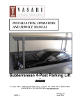
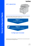
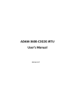
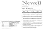
2-346-297-21 (1) AUDIO MIXER SRP-V110 Operating instructions Table of Contents Main characteristics ............................... Dimensions .............................................. 2 2 Connections example ............................ Name and function of each part ........... MONO INPUT section .............................. STEREO INPUT section ............................. MONITOR section ................................... MASTER section ..................................... Back panel section ................................. 3 4 4 6 8 9 !º Block diagram ......................................... Main specifications ................................ Trouble-shooting guide ......................... !™ !£ !¢ Before operating the unit, please read this manual and the supplied “WARNING” thoroughly and retain it for future reference. Precautions On safety (Refer to the supplied “WARNING”.) • Should any liquid or solid object fall into the cabinet, unplug the unit and have it checked by qualified personnel before operating it any further. • Unplug the unit from the wall outlet if it is not to be used for an extended period of time. To disconnect the cord, pull it out by grasping the plug. Never pull the cord itself. On installation • Do not install the unit in a location near heat sources such as radiators or air ducts, or in a place subject to direct sunlight, excessive dust, mechanical vibration or shock. On operation • Before making program source connections, be sure to turn the power switch off and unplug the unit. • When the unit is not used, turn the power off to conserve energy and to extend the useful life of your unit. On cleaning the cabinet Clean the cabinet, panel and controls with a soft cloth lightly moistened with mild detergent solution. Do not use any type of abrasive pad, scouring powder or solvent such as alcohol or benzine. On repacking Do not throw away the carton and the packing material. It makes an ideal container for transporting the unit. When shipping the unit for repair work or to another location, repack it as it was. If you have any questions or problems concerning your unit, please contact your nearest Sony dealer. To prevent fire or shock hazard, do not expose the unit to rain or moisture. To avoid electrical shock, do not open the cabinet. Refer servicing to qualified personnel only. This symbol is intended to alert the user to the presence of uninsulated "dangerous voltage" within the product's enclosure that may be of sufficient magnitude to constitute a risk of electric shock to persons. This symbol is intended to alert the user to the presence of important operating and maintenance (servicing) instructions in the literature accompanying the appliance. *The caution marking is put on the bottom enclosure. 1998 by Sony Sound Tec Corporation Main characteristics This is a small, multi-functional eight-group buses audio mixer combined with a small/mid-sized SR system and multi track recorder, etc. that supports recording systems. Equipped with 10 channels of mono input, 4 channels of stereo input, and 4 channels of auxiliary stereo input Equipped with 8 AUX channels AUX 1/2 can be used as STEREO AUX of the pre-fader. AUX 3/4 can (simultaneously) switch between the pre and post faders. AUX5/6 can be switched to AUX7/8 using the fader. All output systems can be monitored Despite its small size, it can provide support in various ways using a variety of input systems. AFL is installed in all outputs. GROUP and AUX 1/2 can be monitored in stereo. Simple connection to multi-track recorders This (9U) size can be installed onto a standard 19 inch rack using the optional MU-110BK. The TAPE IN connectors and GRP/DIRECT OUT connectors are equipped with 8 channels enabling simple connection to multi-track recorders. Smooth operations are possible from recording to mixing down each track This enables all operations up until the mix down stage without changing connections by simply switching between the TAPE, MONI, and DIRECT buttons. Dimensions 396 (155/8) 86 (31/2) 120 (43/4) 36 (17/16) 430 (17) 2 Unit : mm (inch) Connections example SR system connection Main characteristics Dimensions Keyboard Compressor AUDIO MIXER SRP-V110 Microphone CD or MD Player Compressor Connections example Graphic Equalizer Graphic Equalizer Effector Power Amplifier Power Amplifier Main Speaker Monitor Speaker Recording system connection Keyboard Multi Track Recorder Compressor Microphone CD or MD Player AUDIO MIXER SRP-V110 Monitor Speaker Effector DAT(Master Recorder) 3 Name and function of each part MONO INPUT section 1 POWER switch When the switch is pressed to the ON side, the power is turned on. 2 LEVEL control ON 1 POWER OFF 1 2 LEVEL TAPE 2 LCF +10 -10 5 6 TAPE LEVEL LCF +10 -10 -40 -60 LEVEL -40 -60 +10 -10 HIGH 3 4 HIGH -15 +15 -15 +15 -15 500 1.5K 500 1.5K 500 100 10K 100 10K 100 MID MID 7 -15 8 +15 -15 +15 -15 +15 LOW -15 +15 AUX 9 -15 AUX 1-2 MONI 1 2 -∞ 0 1-2 MONI 1 2 -∞ 0 1 !º !™ -∞ 0 -∞ 0 0 -∞ !£ 0 -∞ 57 -∞ 5 7 -∞ 0 -∞ 0 68 -∞ !§ - 0 ON ON PFL PFL L R ODD EVEN L ODD PEAK +10 L-R +5 @º 0 -5 1-2 3-4 5-6 -10 !∞ !¶ !• 0 -5 1-2 3-4 7-8 !ª 5-6 7-8 -20 DIRECT DIRECT -∞ -∞ 6 MID (Mid equalizer) frequency control This varies the central frequencies of the mid equalizer between 100 Hz - 10 kHz. 7 MID (Mid equalizer) level control This varies the mid equalizer level between –15 dB - +15 dB. The equalizer is a peaking type. 8 LOW (Low equalizer) level control L-R +5 -10 -20 4 L ODD R EVEN PEAK +10 !¢ 68 -∞ 0 This suppresses frequencies of 80 Hz or lower from the channel signal at 12 dB/oct (12 decibels per octave) when it is on. This function is very effective for removing “touch noise” that occurs when a microphone is being held, and “blow noise” caused by breathing. This varies the high equalizer level between –15 - +15 dB. The equalizer is a 12 kHz shelving type. 4 -∞ This switches the signal input from the MIC/LINE connectors to the TAPE IN connectors. Using this function, sounds, such as those from a multi-track recorder connected to the TAPE IN connectors, can be input to each channel without changing connections. (Channels 1 - 8 only) 5 HIGH (High equalizer) level control 3 4 -∞ !¡ -∞ 3 3 TAPE button 4 LCF (Low Cut Filter) button -15 LOW This controls the input signals from the MIC or LINE connectors at a suitable level. When connected to the MIC connector, the input signal level can be controlled between –10 - –60 dBu, and when connected to the LINE connector, it can be controlled between +10 –40 dBu. In order to control the input signal at a suitable level, set the meter to VU operation, press the PFL button of the channel to be controlled to display the signal level on the meter. In this state, turn the LEVEL control to control the signal so that 0VU display on the meter is lit sometimes. @¡ This varies the low equalizer level between –15 dB - +15 dB. The equalizer is a 40 Hz peaking type. 9 AUX 1-2 PAN control When turned towards the “1”, sound is shifted to the AUX 1 bus, and when turned in the “2” direction, it is shifted to the AUX 2 bus. When turned to the maximum in either direction, the output level is increased by +3 dB. !º AUX 1-2 control This controls the level that is sent to the AUX 1/2 buses. This AUX is a pre-fader (splitting the signal before the channel fader). It is used to create a separate balance mix and stereo monitor, as it does not depend on the position of the channel fader. This changes the function of the AUX 1/2. When it is off, the AUX 1-2 PAN control and AUX 1-2 control operate as normal AUX. When it is on, the input signals from the TAPE IN connectors (or MIC/LINE connectors if the TAPE button is turned on) are sent to the AUX 1/2 buses. Sounds, such as those from a multi-track recorder that has been connected to the TAPE connectors, can be monitored through the AUX 1/2 output using this function. (MONO INPUT 1 - 8 only) !™ AUX 3 and 4 controls These control the levels that are sent to the AUX 3 and 4 buses. These AUX’s can switch between the pre-fader and post fader (splitting the signal after it has passed through the channel fader) by using the PRE switch. (Refer to the MASTER section “2 PRE button”) !£ AUX 5/7 and 6/8 controls These control the levels that are output to the AUX 5/7 and 6/8 buses. These AUX’s are post faders. As a result, the AUX level changes depending on the position of the channel fader. This is used when sending signals to the effector, etc. to be connected externally. !¢ AUX 7/8 button When turned in the “L ODD” direction, sound is shifted to the MASTER L, GROUP 1, 3, 5 and 7 (odd channel) buses, and when turned in the “R EVEN” direction, sound is shifted to the MASTER R, GROUP 2, 4, 6, and 8 (even channel) buses. When turned to the maximum in either direction, the output level is increased by +3 dB. !¶ PFL button When turned on, the signals before they pass through the channel fader are routed to the PHONES connector and the MONITOR OUTPUT connectors, while displaying the level on the meter. When PFL buttons for a number of channels are pressed simultaneously, a mixed signal is routed. In this case, signals from channels whose AFL button is turned on are not output. Name and function of each part !¡ MONI button !§ PAN control !• PEAK indicator This is lit up whenever the signal level, after passing through the equalizer, is within 3 dB of the maximum level. When this LED is lit, the signal is excessive, and must be controlled using the LEVEL control. When the MIC connector is used, change it to the LINE connector. !ª Assign buttons When the L-R button is pressed, the signal is routed to the MASTER L/R bus, and when the 1/2, 3/4, 5/6 or 7/8 buttons are pressed, the signal is routed to each group bus. @º Channel fader This sets the signal level for the channels. @¡ DIRECT button When this button is turned off, the signals from the GROUP bus are output; and when it is turned on, the post fader signals from the MONO INPUT channels 1 - 8 are output to the GRP/DIRECT OUT 1 - 8 connectors. These send the signals to the AUX 5/6 buses when turned off, and to the AUX 7/8 buses when turned on. !∞ ON button * 0 dBu=0.775 V When turned on, the signals from the channels are routed to each output. However, the PFL function is available even if this switch is turned off. 5 Name and function of each part STEREO INPUT section ST5 ST6 ST7 ST8 !∞ -∞ 2 0 -∞ 0 -∞ ST2 ST3 ST4 -10dBs -10dBs -10dBs -15 +15 -15 +15 -15 +15 HIGH -15 +15 -15 +15 -15 +15 MID 4 LOW 5 0 -∞ 0 -∞ 0 -∞ 0 0 -∞ 0 -∞ 0 -∞ 0 L-R 0 -5 1-2 3-4 5-6 -10 --∞ 0 -∞ 0 0 -∞ 0 -5 3-4 5-6 -10 7-8 LOW AUX 1-2 0 3 -∞ 0 -∞ 0 -∞ 0 4 57 57 8 68 68 -∞ 0 0 ON ON PFL PFL L R ODD EVEN PEAK +10 1-2 +15 4 L-R +5 -15 MID 3 PEAK +10 +15 -∞ L R ODD EVEN R EVEN PEAK +5 0 PFL L ODD -15 1-2 -∞ ON PFL +15 AUX -∞ 0 -15 LOW 6 8 -∞ +10 +15 5 7 ON L R ODD EVEN -15 1 HIGH MID 4 68 !º +15 3 5 7 0 -15 1-2 -∞ 4 7 +15 AUX 3 6 -15 LOW 1-2 -∞ HIGH MID AUX 6 0 ST1 3 !¢ -∞ -10dBs HIGH -∞ 0 PEAK +10 L-R +5 0 -5 1-2 3-4 5-6 -10 7-8 9 !¡ !™ L-R +5 0 -5 1-2 3-4 5-6 -10 7-8 7-8 -20 -20 -20 -20 -∞ -∞ -∞ -∞ !£ ST1 - ST4 channels 1 –10 dBs button When this button is turned off, the reference input level is +4 dBu; and when it is turned on, it is –10 dBu. 2 HIGH (High equalizer) level control This varies the high equalizer level between –15 - +15 dB. The equalizer is a 12 kHz shelving type. 3 MID (Mid equalizer) level control 4 LOW (Low equalizer) level control This varies the low equalizer level between –15 - +15 dB. The equalizer is a 40 Hz peaking type. 5 AUX 1-2 control This controls the level to be sent to AUX 1/2 buses. The signal that has been input to L is routed through the AUX 1 bus, while the signal that has been input to R is routed through the AUX 2 bus. This AUX is a prefader (splitting the signal before the channel fader). Thus, this is used to create a separate balance mix and stereo monitor, as it does not depend on the position of the channel fader. 6 AUX 3 and 4 controls These control the levels to be sent to the AUX 3/4 buses. In this case, the L and R signals are mixed. This AUX can switch between the pre-fader and post fader (which splits the signal after the channel fader) using the PRE button. (Refer to the MASTER section “2 PRE button”) 7 AUX 5/7 and 6/8 controls These control the levels that are sent to the AUX 5/7 and 6/8 buses. In this case, the L and R signals are mixed. These AUX’s are post faders. As a result, the AUX level changes depending on the position of the channel fader. This is used when sending signals to the effector, etc. to be connected externally. 8 AUX 7/8 button These output the signals to the AUX 5/6 buses when turned off, and to the AUX 7/8 buses when turned on. When turned on, the signals from the channels are routed to each output. However, the PFL function is available even if this switch is turned off. !º Balance control When turned in the “L ODD” direction, sound is shifted to the MASTER L, GROUP 1, 3, 5, and 7 (odd channel) buses, and when turned in the “R EVEN” direction, sound is shifted to the MASTER R, GROUP 2, 4, 6, and 8 (even channel) buses. When turned to the maximum in either direction, the output level is increased by +3 dB. !¡ PFL button Name and function of each part This varies the mid equalizer level between –15 - +15 dB. The equalizer is a 2.5 kHz peaking type. 9 ON button When turned on, the signals in stereo before they pass through the channel fader are routed to the PHONES connector and the MONITOR OUTPUT connectors, while displaying the level on the meter. When PFL buttons for a number of channels are pressed simultaneously, the mixed signal is routed. In this case, signals from channels whose AFL button is turned on are not output. !™ PEAK indicator This is lit up whenever the signal level, after passing through the equalizer, is within 3 dB of the maximum level. When this LED is lit, the signal is excessive, and must be controlled using the LEVEL control. !£ Assign buttons When the L-R button is pressed, the signal is routed to the MASTER L/R buses, and when the 1/2, 3/4, 5/6, or 7/8 buttons are pressed, the signal is routed to each group bus. !¢ Channel fader This sets the signal level for the channels. ST5 - ST8 channels ST5 - ST8 channels are auxiliary stereo input channels. Signals from these channels are only routed to the MASTER L/R buses. !∞ Channel volume control This controls the level that is routed to the MASTER L/ R buses. 7 Name and function of each part MONITOR section 1 PHONES (headphones) connector Phone jack (Tip: L, Ring: R, Sleeve: GND) This is the connector that the headphones are connected to. The same signals are output as those from the MONITOR OUTPUT connectors, and signals from channels whose PFL or AFL buttons are turned on can be confirmed. 2 PEAK meter indicator AUDIO MIXER SRP-V110 1 This is lit up when the level meter is used as a peak meter. PHONES 3 VU meter indicator 2 3 PEAK 4 8 PEAK VU 5 POWER +15 +5 +13 +11 +3 +1 +10 +9 0 -1 +7 -3 +5 +3 -5 -7 0 -10 -10 -20 +48V 6 PFL 7 R L AFL MONO MONITOR L/ODD 9 R/EVEN -∞ 0 AUX MASTER 0 AFL -∞ 0 AFL 0 AFL 6 +48 V indicator 3 -∞ +10 0 AFL PRE TO L-R 4 -∞ 2TR IN 7 PFL indicator 5 AUX 1-2 +10 This is lit up when the PFL button of any channel is turned on. 0 AFL 6 -∞ GRP1-2 +10 0 GRP3-4 AFL 8 PEAK button 7 -∞ When off, the level meter operates as the VU meter, and when on it switches to operating as the PEAK meter. GRP5-6 +10 0 AFL 8 -∞ This is lit up when the power (DC +48 V) for condenser microphone is output. +10 0 AFL -∞ This displays the level of whichever channels PFL or AFL buttons are turned on. The level meter in this system can be switched between PEAK operation and VU operation. Whichever of the PEAK or VU meters indicator is lit shows the scale to use. During PEAK or VU operation, the “0 ” represents the reference level in both the PEAK and VU meters. This is lit up when the power is turned on. +10 PRE 4 LEVEL meter 5 POWER indicator 2TR IN 1-2 -∞ !º This is lit up when the level meter is used as a VU meter. GRP7-8 +10 AFL AFL AFL 1-2 3-4 5-6 AFL AFL 7-8 L-R 9 MONITOR control +10 +5 0 -5 -10 -20 -∞ 8 This controls the output levels of the PHONES and MONITOR OUT connectors. !º AFL MONO buttons This outputs an AFL mono signal that is routed through the PHONES and MONITOR connectors. When the L/ODD button is turned on, sound is only routed through the L and odd channels, and when the R/EVEN button is turned on, sound is only routed through the R and even channels. MASTER section 1 AUX MASTER controls This controls the output level to the AUX OUTPUT connector. 2 PRE buttons This switches AUX 3 and AUX 4 for all channels between the pre-fader and post fader. It is switched to pre-fader when it is on, and post fader when it is off. 3 AFL buttons AUDIO MIXER SRP-V110 PHONES PEAK PEAK VU POWER +15 +5 +13 +11 +3 +1 +10 +9 0 -1 +7 -3 +5 +3 -5 -7 0 -10 -10 -20 +48V 4 2TR IN level control PFL This controls the level of the signals that are input from the 2TR IN connector. R L AFL MONO MONITOR L/ODD This sends each signal to the MASTER L/R bus. 2TR IN 4 1-2 +10 -∞ 0 AFL PRE 5 TO L-R button R/EVEN -∞ 0 AUX MASTER 0 AFL -∞ 0 -∞ +10 0 AFL PRE TO L-R 4 -∞ +10 2TR IN 0 AFL 1 5 -∞ AUX 1-2 +10 0 AFL 6 -∞ 3 GRP1-2 5 +10 0 GRP3-4 AFL 7 -∞ GRP5-6 +10 0 AFL 8 -∞ 6 GROUP faders This controls the level of the signals to be routed to the MASTER L/R bus when signals are routed from the GROUP bus to the GRP/DIRECT OUT connector and the TO L-R button is turned on. Each GROUP fader controls the signal level of every 2 channels, and each channel is not controlled one by one. AFL 3 2 Name and function of each part The signals after the AUX MASTER volume are routed to the PHONES or MONITOR OUT connectors, and displays the level on the meter. When the AFL buttons for a number of channels are turned on simultaneously, they are output after being mixed. However, when a PFL button is turned on, signals from channels whose AFL buttons are pressed are not routed, and only signals from channels whose PFL buttons are pressed are routed. GRP7-8 +10 AFL AFL AFL AFL AFL 1-2 3-4 5-6 7-8 L-R 7 7 AFL buttons The signals after the GROUP fader or L/R fader are routed to the PHONES and MONITOR OUT connectors, and displays their levels on the meter. However, when a PFL button is turned on, signals from channels whose AFL buttons are pressed are not routed, and only signals from channels whose PFL buttons are pressed are routed. When the AFL buttons for a number of channels are turned on simultaneously, a mixed signal is routed. +10 8 L-R fader +5 6 0 -5 8 This controls the level of the signals that are routed from the MASTER L/R bus to the MASTER OUTPUT connectors. -10 -20 -∞ 9 Name and function of each part Back panel section 74 5 STEREO INPUT ST5 ST2 ST6 R L L(MONO) R GRP/ DIRECT OUT ST1 L(MONO) R TAPE IN MONO INPUT 8 7 L(MONO) INSERT LINE INSERT LINE MIC ON OFF !£ !º 8 R +48V MONITOR OUT R ST8 L ST7 L(MONO) R L ST4 R 10 ST3 R L(MONO) L(MONO) MIC R OUTPUT INSERT R R L 8 L L OUT 7 6 5 4 3 IN R 2TR MASTER !™ 1 MONO INPUT MIC connectors XLR-3-31 type (Balanced, reference level: –60 - –10 dBu) (Pin No.1: ground, No.2: hot, No.3: cold) These are input connectors for the MONO INPUT channels. Microphones can be connected. 2 MONO INPUT LINE connectors Phone jacks (Balanced, reference level: –40 - +10 dBu) (Tip: hot, Ring: cold, Sleeve: ground) These are input connectors for the MONO INPUT channels. Line level output equipment can be connected. 3 MONO INPUT INSERT connectors Phone jacks (Unbalanced, reference level: –3 dBu) (Tip: output, Ring: input, Sleeve: ground) These are INSERT IN/OUT connectors for the MONO INPUT channels. External equipment can be inserted before the installed equalizer. Compressors and gates, etc. are connected. 4 TAPE IN connectors Phono jacks (Unbalanced, reference level: –10 dBu) These are TAPE IN connectors for MONO INPUT channels. They connect the output for each track, such as from a multi-track recorder, etc., and are used for monitoring or laying down tracks. 10 0 !¡ 96 AUX OUTPUT 8 5 STEREO INPUT connectors Phone jacks (ST1 – ST4) (Tip: hot, Ring: cold, Sleeve: ground) (Balanced, reference level: +4/ –10 dBu) Phone jacks (ST6, ST8) (Unbalanced, reference level: –10 dBu) Phono jacks (ST5, ST7) (Unbalanced, reference level: –10 dBu) These are input connectors for the STEREO INPUT channels. Line level output equipment with a reference level of between +4 dBu and –10 dBu can be connected for ST1 - ST4, and line level output equipment with a reference level of –10 dBu can be connected for ST5 - ST8 in stereo. Signals are internally distributed to the R side when only the L (MONO) connector is connected for ST1 - ST4, ST6 and ST8. 6 2TR IN connectors Phono jacks (Unbalanced, reference level: –10 dBu) These are connectors to input signals, such as those from DAT or MD recorders. The level is controlled by the 2TR IN level control on the MASTER section. 7 GRP/DIRECT OUT connectors Phono jacks (Unbalanced, reference level: –10 dBu) These output each GROUP bus signal. When the DIRECT button for the MONO INPUT 1 - 8 channels is turned on, they become direct output connectors that output post fader signals from each MONO INPUT channel. 3 2 GRP/ DIRECT OUT MONO INPUT 7 INSERT TAPE IN MONO INPUT 2 MIC 1 LINE INSERT LINE INSERT LINE INSERT LINE 1 MIC INSERT LINE INSERT LINE INSERT LINE MIC 2 9 INSERT 4 MIC 3 LINE 3 MIC MIC 6 2 5 1 5 MIC MIC 6 1 Name and function of each part 4 74 8 AUX OUTPUT connectors Phone jacks (Unbalanced, reference level: +4 dBu) 9 2TR OUT connectors Phono jacks (Unbalanced, reference level: –10 dBu) These distribute and output the MASTER OUTPUT L/ R signals. They are connected to DAT or MD recorders, or equivalent. !º MONITOR OUT connectors Phone jacks (Unbalanced, reference level: +4 dBu) These output the same signals as the PHONES connector, and signals from any channels whose PFL or AFL buttons are turned on can be confirmed. !£ +48 V button This is the button to supply power (DC +48 V) for condenser microphones to the MIC connectors of the MONO INPUT channels 1 - 8. When this button is turned on, DC +48 V is output to all MIC connectors. Caution • Before turning on the +48 V button or after changing the cable connection, turn down the output fader or the output volume. • The line equipment must be connected to the LINE input side. • When a dynamic microphone is used in conjunction with a microphone that uses +48 V power, the dynamic microphone may under-perform. !¡ MASTER OUTPUT connectors XLR-3-32 type (Balanced, reference level: +4 dBu) (Pin No. 1: ground, No. 2: hot, No. 3: cold) * 0 dBu=0.775 V !™ MASTER INSERT connectors Phone jacks (Unbalanced, reference level: –6 dBu) (Tip: output, Ring: input, Sleeve: ground) These are the INSERT IN/OUT connectors of the MASTER OUTPUT. External equipment can be inserted before the L/R fader. They are connected to the compressor or gate, etc. !¡ 11 AUX 5-8 PFL L PFL R CONTROL GP OUT1-8 L-R GROUP 1-8 AUX 1-2 AUX 3-4PRE AUX 3-4POST Block diagram +48V FADER PEAK TAPE MIC -10 - -60dBs L-R ON LCF FADER 1-2 INSERT LCF LINE +10 - -40dBs -20dB STEREO L OUTPUT +4dBs PAN EQ 3-4 FREQ LEVEL 5-6 LEVEL 7-8 LOW MID HIGH INSERT MONI STEREO R OUTPUT +4dBs PAN TAPE INPUT -10dBs INSERT AUX1-2 AUX3 AFL ATT GROUP/DIRECT OUTPUT -10dBs ATT AUX4 DIRECT 2TR OUTPUT -10dBs ATT AFL MONO 7/8 LEVEL METER AUX5/7 7/8 PEAK AUX6/8 L/ODD PFL PHONES MONO INPUT 1-8 R/EVEN +48V PEAK FADER PAN -20dB MONITOR 1-2 EQ LCF LINE +10 - -40dBs MONITOR OUTPUT +4dBs L-R ON LCF MIC -10 - -60dBs 3-4 FREQ LEVEL FADER 5-6 LEVEL 7-8 LOW MID HIGH INSERT PAN AUX1-2 TO L-R GROUP1-2/3-4/5-6/7-8 OUTPUT AUX3 AFL AUX4 7/8 AUX5/7 7/8 AUX6/8 AUX1-2 AUX1 OUTPUT +4dBs PFL MONO INPUT 9-10 AUX2 OUTPUT +4dBs AFL PEAK FADER ON BAL -10dBs EQ TO L-R L-R L (MONO) +4/-10dBs + 1-2 + 3-4 R +4/-10dBs AUX3/4 AUX3/4 OUTPUT +4dBs 5-6 LEVEL PRE 7-8 LOW MID HIGH AFL AUX1-2 AUX5/6/7/8 AUX3 AUX5/6/7/8 OUTPUT +4dBs AFL AUX4 AFL 2TR IN 7/8 2TR INPUT -10dBs AUX5/7 7/8 TO L-R AUX6/8 +48V PFL +48V STEREO INPUT 1-4 LEVEL L -10dBs R -10dBs STEREO INPUT 5,7 LEVEL L (MONO) -10dBs R -10dBs STEREO INPUT 6,8 12 !™ Main specifications Name MONO INPUT Connector type Circuit Reference level Maximum level Impedance Suitable load impedance MIC XLR-3-31 type Balanced –60 - –10 dBu –37 - +13 dBu 2.2 kΩ — LINE ø 6.3 Phone jack –40 - +10 dBu –17 - +27 dBu 22 kΩ — TAPE INPUT Phono jack Unbalanced –10 dBu +13 dBu 10 kΩ — INSERT INPUT ø 6.3 Phone jack Unbalanced –3 dBu +20 dBu 30 kΩ — –3 dBu +20 dBu 47 Ω 600 Ω or more INSERT OUTPUT STEREO INPUT ø 6.3 Phone jack Balanced –10/+4 dBu +13/+27 dBu 3.3 kΩ or more — 5,7 Phono jack Unbalanced –10 dBu +27 dBu 10 kΩ or more — 6,8 ø 6.3 Phone jack Unbalanced –10 dBu +27 dBu 10 kΩ or more — AUX OUTPUT ø 6.3 Phone jack Unbalanced +4 dBu +20 dBu 100 Ω 600 Ω or more GROUP/DIRECT OUTPUT Phono jack Unbalanced –10 dBu +10 dBu 320 Ω 10 kΩ or more INPUT Phono jack Unbalanced –10 dBu +27 dBu 10 kΩ or more — OUTPUT Phono jack Unbalanced –10 dBu +10 dBu 320 Ω 10 kΩ or more Balanced +4 dBu +24 dBu 47 Ω 600 Ω or more Unbalanced –6 dBu +20 dBu 30 kΩ or more — –6 dBu +20 dBu 47 Ω 600 Ω or more 2TR XLR-3-32 type STEREO OUTPUT INSERT INPUT ø 6.3 Phone jack INSERT OUTPUT MONITOR OUTPUT PHONES ø 6.3 Phone jack Unbalanced +4 dBu +20 dBu 100 Ω 600 Ω or more ø 6.3 Phone jack Unbalanced — 40 mW + 40 mW — 8 Ω or more Audio section General section Frequency response +0.5/–1.0 dB (20 Hz – 50 kHz) +0.5/–0.5 dB (20 Hz – 20 kHz) Total harmonic distortion Less than 0.005% (MIC INPUT: –60 dBu, L-R OUTPUT: +14 dBu, 1 kHz) E.I.N Less than –129 dBu (MIC INPUT: –60 dBu) Residual noise level Less than –95 dBu (20 Hz - 20 kHz, L-R OUTPUT FADER: – ∞) Less than –82 dBu (20 Hz - 20 kHz, L-R OUTPUT FADER: 0, 14 ch routed) Less than –106 dBu (20 Hz - 20 kHz, GROUP OUTPUT FADER: – ∞) Less than –95 dBu (20 Hz - 20 kHz, GROUP OUTPUT FADER: 0, 14 ch routed) Crosstalk Less than –90 dB (Fader down, 1 kHz) Less than –98 dB (ON button: OFF, 1 kHz) (0 dBu=0.775 V) Power supply voltage Refer to the supplied “WARNING ”. Power consumption 50 W Operating temperature 0°C – 40°C Storage temperature –20°C – 60°C Mass Approx. 8.7 kg External dimensions 430 × 120 × 396 mm (17 × 4 3/4 × 15 5/8 inches) (width/height/depth, excluding protruding parts) Supplied Accessories Operating instructions (1), WARNING (1) Block diagram Main specifications 1-4 Specifications and external appearance are subject to change for improvement without prior notice. !£ 13 Trouble-shooting guide In the event of any unexpected problems, please double-check the following points. If after that, normal operation cannot be resumed, contact the store from which the item was purchased, or your nearest Sony dealer. Condition Causes/Solutions When the POWER switch is turned on, the power indicator does not light up, nor is any sound output. • Check that the power cord is connected. Although the POWER indicator is lit, no sound is output. • Check whether or not the ON button is turned off. (Pages 5 and 7) • Check whether the assign button is correctly pressed. (Pages 5 and 7) No sound is output from the TAPE IN connector. • Check whether or not the TAPE button is turned off. (Page 4) No sound is output from the GROUP bus. • Check whether or not the DIRECT button is turned on. (Page 5) No sound is output from the 2TR IN connector. • Check whether or not the TO L-R button is turned off. (Page 9) No sound is output from the AUX 5, 6, 7 and 8 buses. • Check whether the AUX 7/8 button is pressed correctly. (Pages 5 and 7) No sound is output from the PHONES connector or the MONITOR OUT connector. • Check whether or not all of the AFL buttons are turned off. (Page 9) • Check whether or not the PFL button is turned on. (Pages 5 and 7) Sound from the AUX 1/2 and GROUP bus is output through the MASTER OUTPUT. • Check whether or not the TO L-R button is turned on. (Page 9) The sound is distorted. • Check whether the settings of the LEVEL controls and –10 dBu button are correct. (Pages 4 and 7) • Check whether or not the line level output equipment is connected to the MIC connector. (Page 10) 14 !¢ 15 Printed in Japan