1
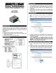
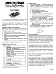
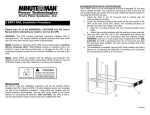
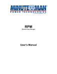
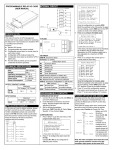
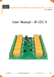
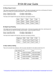
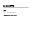
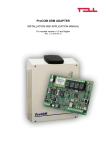
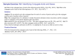
INTERNAL CIRCUIT
Common
R1
R2
R3
PROGRAMMABLE RELAY CARD
R4
USER MANUAL
R5
+5V
INTRODUCTION
This Programmable Relay card is an UPS management product with 6
relay output contacts for monitoring the status and 1 input contact as a
shutdown UPS or a battery test command.
Features:
Monitors UPS events.
6 programmable relay output contacts.
Configurable normal open or normal close for each relay contact.
Configurable UPS shutdown delay time.
Configurable input signal as shutdown UPS or battery test.
Has the ability to protect up to 6 computers unattended shutdown
gracefully.
R6
CPU Pin
GND-R
Input
OUTLINE
GND-R
Common
R1
R2
R3
R4
R5
R6
Input
Tx
Rx
GND-C
SPECIFICATIONS
Size Net (L x W)
Weight Net
Operating Temperature
Operating Humidity
Power Input Volts
Power Input Current
Power Consumption
Relay Contacts Volts
Relay Contacts Current
5.1” x 2.4”
0.50 lbs
0 ~ 40° C
10 ~ 80 %
8 ~ 20V DC
10mA
1.2 Watts
24VDC (max)
1A (max)
INSTALLATION
Note: These Programmable Relay cards are designed to be Hot
Swappable, but there is a remote chance that when Hot-Swapping the
Programmable Relay card that the UPS will shutdown. MINUTEMAN
recommends following steps 1 through 4 when installing the
Programmable Relay card, but to hot-swap, skip to step number 3.
1. Turn off all the equipment that is plugged into the UPS.
2. Turn off the UPS and unplug the UPS’s power cord from the AC wall
outlet.
3. Remove the option slot cover plates from the rear panel of the UPS.
4. Insert the Programmable Relay card into the option slot, and secure
with the retaining screws.
I/O PINOUT
GND-R: Ground for relays
Common: 12~24VDC
Default Alarm Event
R1
Summary Alarm
R2
Power Fail
R3
Battery Low
R4
On Bypass
R5
Overload
R6
Over Temperature
Input: Remote shutdown or battery test
Tx: Transmit to PC, connect to sub9-pin2
Rx: Receive from PC, connect to sub9-pin3
GND-C: Ground for configuration Tx and Rx pins
OFF (Default)
ON
SW1 Normal open
Normal close
SW2 Default settings
Customized settings
PROGRAMMABLE CONTACTS
APPLICATION EXAMPLE
Set SW1 and SW2 to the OFF position. Apply 12VDC to the Common
contact and connect the lamps to R1~R6 terminals. Install a push button
from the Common contact to the input terminal. Press the button for at
least 3 seconds to shutdown the UPS remotely.
Common
SW1
SW2
+12V
GND-R
R1
Summary Alarm
R2
Power Fail
R3
Battery Low
R4
On Bypass
R5
Overload
R6
Over Temperature
Input
Shutdown UPS
COMMUNICATION SETUP
1. Connect Tx to pin2, Rx to pin3 and GND-C to pin5 of PC RS232 port.
2. In the Windows environment, launch the Hyper-Terminal program then
open the specified COM port.
3. Set the following properties:
Baud rate: 2400, Data Bits: 8, Parity: None
Stop Bit: 1, Flow Control: None
CONFIGURATION
1. Press <Enter> to get the main menu of the Programmable Relay card.
+---------------------------+
|
UPS Relay Card
|
+---------------------------+
Firmware Version: Relay Card V1.4
[1].Customize Output Relay
[2].Configure Input Signal
[3] Customize Normal Open or Normal Close
[0].Quit
Please Enter Your Choice =>
2. Press ‘1’ to configure the alarm event for R1~R6.
can be configured for different power events.
Contacts R1~R6
OBTAINING SERVICE
1.
+---------------------------+
|
Customize Output Relay |
+---------------------------+
Relay
Selected Event
[1].Relay1: Summary Alarm
[2].Relay2: Power Fail
[3].Relay3: Battery Low
[4].Relay4: On Bypass
[5].Relay5: Overload
[6] Relay6: Over Temperature
[0].Back To Previous Menu
Please Enter Your Choice =>
Once the configuration is complete switch SW2 MUST be switched to
the ON position to apply the new settings. SW2 MUST remain in the
ON position to use the new settings. Switch SW2 back to OFF position
to reset to the default settings.
3. Press ‘2’ to configure the Input signal.
+---------------------------+
| Configure Input Signal |
+---------------------------+
[1].Act as Shutdown or Test: Shutdown
[2].Input Signal Confirm: 3 Seconds
[3].Delay Before Shutdown: 30 Seconds
[0].Back To Previous Menu
Please Enter Your Choice =>
In this menu, the input signal can be redefined as shutdown UPS or
battery test signal. Meanwhile, the UPS shutdown delay time is also
adjustable to a maximum of 9999 seconds.
4. Press ‘3’ to configure the normal open or normal close for each relay.
+---------------------------+
| Customize Output Relay |
+---------------------------+
Relay Selected Event
[1].Relay1: Normal Close
[2].Relay2: Normal Open
[3].Relay3: Normal Close
[4].Relay4: Normal Open
[5].Relay5: Normal Close
[6].Relay6: Normal Open
[0].Back To Previous Menu
2.
3.
4.
Call your dealer for assistance. If you cannot reach your dealer, or if
they cannot resolve the problem call or fax MINUTEMAN Technical
Support at the following numbers; Voice phone (972) 446-7363, FAX
line (972) 446-9011 or visit our Web site at www.minutemanups.com
the "Discussion Board". Please have the following information
available BEFORE calling the Technical Support Department.
a. Your name and address.
b. Where and when the unit was purchased.
c. All of the model information about your relay card.
d. Any information on the failure.
e. A technician will ask you for the above information and, if
possible, help solve your problem over the phone. In the event
that the unit requires factory service, the technician will issue
you a Return Material Authorization Number (RMA #).
f.
If the relay card is under warranty, the repairs will be done at no
charge. If not, there will be a charge for repair.
Pack the relay card in its original packaging. If the original
packaging is no longer available, ask the Technical Support
Technician about obtaining a new set. It is important to pack the
relay card properly in order to avoid damage in transit. Never use
Styrofoam beads for a packing material.
a. Include a letter with your name, address, daytime phone number,
RMA number, a copy of your original sales receipt, and a brief
description of the problem.
Mark the RMA # on the outside of all packages. The factory cannot
accept any package without the RMA # marked on the outside.
Return the relay card by insured, prepaid carrier to:
Para Systems Inc.
MINUTEMAN UPS
1455 LeMay Drive
Carrollton, TX 75007
ATTN: RMA #
LIMITED PRODUCT WARRANTY
Please Enter Your Choice =>
Once the configuration is complete switch SW2 MUST be switched to
the ON position to apply the new settings. SW2 MUST remain in the
ON position to use the new settings. Switch SW2 back to OFF position
to reset to the default settings. SW1 can be used to change the normal
open or the normal close contacts for all relays. SW1 set to the OFF
position; normal open (default), SW1 set to the ON position; normal
close.
5. Press ‘0’ to quit this configuration session. The system will prompt you
to save or not. Press ‘Y’ to save your settings, ‘N’ to ignore.
POWER OPTION IN WIN 2000/XP
This relay card has the ability to provide UPS signals for Windows
NT4/2000/XP/2003. First connect the RS232 port on the PC to the relay
card as shown:
Common
Para Systems Inc. (Para Systems) warrants this equipment, when properly applied
and operated within specified conditions, against faulty materials or workmanship for a
period of three years from the date of purchase. For equipment sites within the
United States and Canada, this warranty covers repair or replacement of defective
equipment at the discretion of Para Systems. Repair will be from the nearest
authorized service center. Replacement parts and warranty labor will be borne by
Para Systems. For equipment located outside of the United States and Canada,
Para Systems only covers faulty parts. Para Systems products repaired or replaced
pursuant to this warranty shall be warranted for the un-expired portion of the warranty
applying to the original product. This warranty applies only to the original purchaser
who must have properly registered the product within 10 days of purchase.
The warranty shall be void if (a) the equipment is damaged by the customer, is
improperly used, is subjected to an adverse operating environment, or is operated
outside the limits of its electrical specifications; (b) the equipment is repaired or
modified by anyone other than Para Systems or Para Systems-approved personnel;
or (c) has been used in a manner contrary to the product’s User's Manual or other
written instructions.
Any technical advice furnished before or after delivery in regard to use or application of
Para Systems’ equipment is furnished without charge and on the basis that it
represents Para Systems’ best judgment under the circumstances, but it is used at the
recipient’s sole risk.
RTS pin7
GND-R
GND pin5
R1
Power Fail
R2
Battery Low
R3
Except as provided herein, Para Systems makes no warranties, expressed or implied,
including warranties of merchantability and fitness for a particular purpose. Some
states do not permit limitation of implied warranties; therefore, the aforesaid
limitation(s) may not apply to the purchaser.
CTS pin8
DCD pin1
R4
R5
R6
Shutdown UPS
Input
DTR pin4
Then open the power option from control panel and click on the UPS tab to
setup the signals polarity, select Positive for Power Fail, Low Battery and
UPS Shutdown. Since the R1~R6 contacts are programmable, the output
contacts can be configured for 3 computers with 2 signals (power fail and
low battery) or 6 computers with one signal (power fail or low battery).
Note: All of the computers must have the same earth ground
potential. Connect all of the computers input power cords to the
same UPS.
EXCEPT AS PROVIDED ABOVE, IN NO EVENT WILL PARA SYSTEMS BE LIABLE
FOR DIRECT, INDIRECT, SPECIAL, INCIDENTAL, OR CONSEQUENTIAL
DAMAGES ARISING OUT OF THE USE OF THIS PRODUCT, EVEN IF ADVISED
OF THE POSSIBILITY OF SUCH DAMAGE. Specifically, Para Systems is not liable
for any costs, such as lost profits or revenue, loss of equipment, loss of use of
equipment, loss of software, loss of data, cost of substitutes, claims by third parties, or
otherwise. The sole and exclusive remedy for breach of any warranty, expressed or
implied, concerning Para Systems’ products and the only obligation of Para Systems
hereunder, shall be the repair or replacement of defective equipment, components, or
parts; or, at Para Systems’ option, refund of the purchase price or substitution with an
equivalent replacement product. This warranty gives you specific legal rights and
you may have other rights, which vary from state to state.
34000308