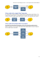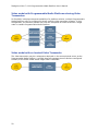
1
Dialogic® Vision™ 1000 Programmable Media Platform User’s Manual January 2011 64-0400-04 www.dialogic.com Copyright and legal notice Copyright © 2006-2011 Dialogic Inc. All Rights Reserved. You may not reproduce this document in whole or in part without permission in writing from Dialogic Inc. at the address provided below. All contents of this document are furnished for informational use only and are subject to change without notice and do not represent a commitment on the part of Dialogic Inc. and its affiliates or subsidiaries (“Dialogic”). Reasonable effort is made to ensure the accuracy of the information contained in the document. However, Dialogic does not warrant the accuracy of this information and cannot accept responsibility for errors, inaccuracies or omissions that may be contained in this document. INFORMATION IN THIS DOCUMENT IS PROVIDED IN CONNECTION WITH DIALOGIC® PRODUCTS. NO LICENSE, EXPRESS OR IMPLIED, BY ESTOPPEL OR OTHERWISE, TO ANY INTELLECTUAL PROPERTY RIGHTS IS GRANTED BY THIS DOCUMENT. EXCEPT AS PROVIDED IN A SIGNED AGREEMENT BETWEEN YOU AND DIALOGIC, DIALOGIC ASSUMES NO LIABILITY WHATSOEVER, AND DIALOGIC DISCLAIMS ANY EXPRESS OR IMPLIED WARRANTY, RELATING TO SALE AND/OR USE OF DIALOGIC PRODUCTS INCLUDING LIABILITY OR WARRANTIES RELATING TO FITNESS FOR A PARTICULAR PURPOSE, MERCHANTABILITY, OR INFRINGEMENT OF ANY INTELLECTUAL PROPERTY RIGHT OF A THIRD PARTY. Dialogic products are not intended for use in medical, life saving, life sustaining, critical control or safety systems, or in nuclear facility applications. Due to differing national regulations and approval requirements, certain Dialogic products may be suitable for use only in specific countries, and thus may not function properly in other countries. You are responsible for ensuring that your use of such products occurs only in the countries where such use is suitable. For information on specific products, contact Dialogic Inc. at the address indicated below or on the web at www.dialogic.com. It is possible that the use or implementation of any one of the concepts, applications, or ideas described in this document, in marketing collateral produced by or on web pages maintained by Dialogic may infringe one or more patents or other intellectual property rights owned by third parties. Dialogic does not provide any intellectual property licenses with the sale of Dialogic products other than a license to use such product in accordance with intellectual property owned or validly licensed by Dialogic and no such licenses are provided except pursuant to a signed agreement with Dialogic. More detailed information about such intellectual property is available from Dialogic’s legal department at 926 Rock Avenue, San Jose, California 95131 USA. Dialogic encourages all users of its products to procure all necessary intellectual property licenses required to implement any concepts or applications and does not condone or encourage any intellectual property infringement and disclaims any responsibility related thereto. These intellectual property licenses may differ from country to country and it is the responsibility of those who develop the concepts or applications to be aware of and comply with different national license requirements. Dialogic, Dialogic Pro, Dialogic Blue, Veraz, Brooktrout, Diva, Diva ISDN, Making Innovation Thrive, Video is the New Voice, Diastar, Cantata, TruFax, SwitchKit, SnowShore, Eicon, Eicon Networks, NMS Communications, NMS (stylized), Eiconcard, SIPcontrol, TrustedVideo, Exnet, EXS, Connecting to Growth, Fusion, Vision, PowerMedia, PacketMedia, BorderNet, inCloud9, I-Gate, Hi-Gate, NaturalAccess, NaturalCallControl, NaturalConference, NaturalFax and Shiva, among others as well as related logos, are either registered trademarks or trademarks of Dialogic Inc. and its affiliates or subsidiaries. Dialogic's trademarks may be used publicly only with permission from Dialogic. Such permission may only be granted by Dialogic’s legal department at 926 Rock Avenue, San Jose, California 95131 USA. Any authorized use of Dialogic's trademarks will be subject to full respect of the trademark guidelines published by Dialogic from time to time and any use of Dialogic’s trademarks requires proper acknowledgement. The names of actual companies and products mentioned herein are the trademarks of their respective owners. This document discusses one or more open source products, systems and/or releases. Dialogic is not responsible for your decision to use open source in connection with Dialogic products (including without limitation those referred to herein), nor is Dialogic responsible for any present or future effects such usage might have, including without limitation effects on your products, your business, or your intellectual property rights. Any use case(s) shown and/or described herein represent one or more examples of the various ways, scenarios or environments in which Dialogic® products can be used. Such use case(s) are non-limiting and do not represent recommendations of Dialogic as to whether or how to use Dialogic products. Revision history Revision Release date Notes 64-0400-04 Rev A January 2011 BK, Dialogic® Vision™ 1000 Programmable Media Platform 5.1 and Dialogic® Vision™ 1000 Video Gateway 5.1 64-0400-03 Rev A May 2010 BK, Dialogic® Vision™ 1000 Programmable Media Platform 5.0 and Dialogic® Vision™ 1000 Video Gateway 5.0 64-0400-02 Rev B December 2009 BK, Dialogic® Vision™ VX Integrated Media Platform 4.2 and Dialogic® Vision™ CX Video Gateway 4.2 64-0400-02 Rev A August 2009 BK, Dialogic® Vision™ VX Integrated Media Platform 4.2 and Dialogic® Vision™ CX Video Gateway 4.2 64-0400-01 Rev A June 2009 BK, Dialogic® Vision™ VX Integrated Media Platform 4.1 and Dialogic® Vision™ CX Video Gateway 4.1 Last modified: 2011-01-13 Refer to www.dialogic.com for product updates and for information about support policies, warranty information, and service offerings. Table of Contents 1. Introduction .................................................................................................. 9 2. Overview of the Dialogic® Vision™ 1000 Programmable Media Platform ..... 10 Programmable Media Platform overview ................................................................... 10 Software components.......................................................................................... 11 Signaling protocols and models ............................................................................ 11 Media capabilities ............................................................................................... 11 Interfaces .......................................................................................................... 13 Fast call setup .................................................................................................... 14 ISDN models ........................................................................................................ 15 ISDN audio model............................................................................................... 15 ISDN video model ............................................................................................... 15 ISUP models ......................................................................................................... 16 Basic ISUP audio model ....................................................................................... 16 Basic BICC audio model ....................................................................................... 16 Basic ISUP video model ....................................................................................... 17 Basic BICC video model ....................................................................................... 17 ISUP scalable deployment model .......................................................................... 18 ISUP redundant deployment model ....................................................................... 18 IP models ............................................................................................................. 19 IP-only audio model ............................................................................................ 19 IP-only video model ............................................................................................ 20 Models with Video Transcoders ................................................................................ 20 Video Transcoder interconnect ............................................................................. 20 Video model with a single Video Transcoder ........................................................... 21 Video model with multiple Video Transcoders ......................................................... 21 Video model with Programmable Media Platforms sharing Video Transcoders ............. 22 Video model with co-located Video Transcoder ....................................................... 22 Standards............................................................................................................. 23 Document conventions ........................................................................................... 25 Related documentation .......................................................................................... 25 3. Configuring the Dialogic® Vision™ 1000 Programmable Media Platform ..... 27 Overview of configuring the Programmable Media Platform ......................................... 27 Gathering information ............................................................................................ 27 Network configuration information ........................................................................ 28 ISDN configuration information ............................................................................ 28 Trunk configuration information ............................................................................ 28 Signaling server configuration information ............................................................. 30 ISUP configuration information ............................................................................. 31 Video Transcoder configuration information ........................................................... 35 IP-324M configuration information ........................................................................ 35 Ethernet redundancy configuration information ...................................................... 36 Network monitor configuration information ............................................................ 38 Node configuration information............................................................................. 39 SIP load balancing configuration information .......................................................... 39 Logging into the Programmable Media Platform for the first time ................................. 40 Configuring the Programmable Media Platform to use a static IP address ................... 40 Obtaining an IP address through DHCP .................................................................. 41 Accessing the Dialogic Vision Console ...................................................................... 42 Creating or revising a configuration ......................................................................... 44 4 Table of Contents Create a configuration ......................................................................................... 44 Revise a configuration ......................................................................................... 45 Additional configuration tasks ............................................................................... 45 Backing up a configuration ..................................................................................... 45 Restoring a configuration........................................................................................ 46 Accessing the Programmable Media Platform using a secure shell ................................ 47 Resetting the root password ................................................................................... 47 Installing a security certificate ................................................................................ 47 User account management ..................................................................................... 49 Creating a new user account ................................................................................ 49 Modifying a user account ..................................................................................... 49 Removing a user account..................................................................................... 50 Centralized user authentication ............................................................................... 50 Types of LDAP servers ......................................................................................... 50 Configuring the Provider server ............................................................................ 50 Configuring the Consumer server.......................................................................... 51 4. Dialogic® Vision™ Console parameters ........................................................ 52 Configuration menu parameters .............................................................................. 52 Overview ........................................................................................................... 52 Node definition ................................................................................................... 52 Date and Time ................................................................................................... 53 Host IP information ............................................................................................. 54 Resource configuration ........................................................................................ 56 SIP parameters .................................................................................................. 59 RTP parameters .................................................................................................. 60 NbUP circuits...................................................................................................... 62 Trunks .............................................................................................................. 63 PSTN................................................................................................................. 67 Signaling Server ................................................................................................. 68 Options ............................................................................................................. 73 Capacity upgrade................................................................................................ 73 SNMP configuration ............................................................................................. 74 Network redundancy configuration ........................................................................ 75 Video Transcoder ................................................................................................ 76 Import/Export configuration ................................................................................. 77 Operations menu parameters .................................................................................. 77 Services ............................................................................................................ 77 Maintenance ...................................................................................................... 78 Provisioning menu parameters ................................................................................ 79 Routing profiles configuration ............................................................................... 80 Call routing table ................................................................................................ 80 CCXML application configuration ........................................................................... 80 VoiceXML application configuration ....................................................................... 80 Video transcoder resource configuration ................................................................ 80 Monitoring menu parameters .................................................................................. 81 RAID page ......................................................................................................... 81 Trunks page ....................................................................................................... 82 CCXML statistics ................................................................................................. 82 Call Server status ............................................................................................... 83 VoiceXML Interpreter view ................................................................................... 84 VoiceXML Interpreter status ................................................................................. 85 SSML Processor view........................................................................................... 87 5 Dialogic® Vision™ 1000 Programmable Media Platform User's Manual SSML Processor status ........................................................................................ 87 Signaling Monitor................................................................................................ 89 Video Transcoder status ...................................................................................... 89 Network Monitor ................................................................................................. 91 Log files ............................................................................................................ 91 CDR files ........................................................................................................... 92 System menu parameters ...................................................................................... 92 Authentication page ............................................................................................ 92 User administration page ..................................................................................... 93 5. Managing the Dialogic® Vision™ 1000 Programmable Media Platform ........ 94 Working with Programmable Media Platform services ................................................. 94 Viewing Programmable Media Platform information .................................................... 95 Audit tracking ....................................................................................................... 96 Audit tracking console log files ............................................................................. 97 Audit tracking configuration archives ..................................................................... 97 Managing VoiceXML applications .............................................................................. 98 Adding a VoiceXML application ............................................................................. 98 Removing a VoiceXML application ....................................................................... 100 Modifying a VoiceXML application definition .......................................................... 100 Pattern matching syntax .................................................................................... 100 Managing CCXML applications ............................................................................... 102 Default CCXML application ................................................................................. 102 Adding a CCXML application definition ................................................................. 102 Removing a CCXML application definition ............................................................. 105 Modifying a CCXML application definition ............................................................. 105 CCXML application definition pattern matching syntax ........................................... 105 Managing video transcoder resources ..................................................................... 107 Configuring a video transcoder system ................................................................ 107 Defining video transcoder resources for the Programmable Media Platform .............. 108 Specifying video transcoding in a call leg ............................................................. 109 Video transcoder logging ................................................................................... 110 Video call completion to voice service .................................................................... 110 Call logic ......................................................................................................... 111 Using the service .............................................................................................. 111 Configuring streaming-only media server applications .............................................. 112 Working with Ethernet Redundancy ....................................................................... 112 Ethernet redundancy concepts ........................................................................... 113 Configuring the SIP network .............................................................................. 114 Configuring the RTP network .............................................................................. 114 Configuring the Circuit-Switched Signaling network .............................................. 115 Configuring the NbUP network ............................................................................ 115 Configuring the Billing network ........................................................................... 116 Configuring the OA&M network ........................................................................... 117 Configuring the Signaling Redundant network ...................................................... 117 Network redundancy and the network monitor service ............................................. 118 Configuring the network monitor service ............................................................. 118 Out-of-band management .................................................................................... 119 Using the remote management interface ............................................................. 119 Managing Vision Nodes ........................................................................................ 120 Vision node concepts......................................................................................... 120 Vision node guidelines ....................................................................................... 120 Defining a node ................................................................................................ 121 6 Table of Contents Disabling or enabling a node member ................................................................. 121 Removing a node member ................................................................................. 122 Upgrading node capacity ................................................................................... 122 Using SIP load balancing ...................................................................................... 122 How SIP load balancing works ............................................................................ 122 Configuring SIP load balancing ........................................................................... 122 6. Developing VoiceXML applications ............................................................. 124 Overview of developing VoiceXML applications ........................................................ 124 Managing media .................................................................................................. 124 Developing an audio application ............................................................................ 124 Developing a video application .............................................................................. 124 Playing a video message.................................................................................... 124 Recording and posting a video message .............................................................. 125 MPEG-4 limitation for 3G-324M handsets ............................................................. 125 Using the record utterance functionality ................................................................. 126 7. Logging ...................................................................................................... 127 Overview of Programmable Media Platform logging .................................................. 127 Call Server system logs ........................................................................................ 127 Logging levels .................................................................................................. 127 Logging defaults ............................................................................................... 128 Changing the logging level ................................................................................. 128 Changing other logging defaults ......................................................................... 129 Log file format.................................................................................................. 129 VoiceXML Interpreter system logs .......................................................................... 130 Logging levels .................................................................................................. 131 Logging defaults ............................................................................................... 131 Changing the logging level ................................................................................. 132 Changing other logging defaults ......................................................................... 132 Log file format.................................................................................................. 133 SSML Processor system logs ................................................................................. 134 Logging levels .................................................................................................. 135 Logging defaults ............................................................................................... 135 Changing the logging level ................................................................................. 136 Changing other logging defaults ......................................................................... 136 Log file format.................................................................................................. 136 VoiceXML application logs ..................................................................................... 137 Log file format.................................................................................................. 138 SSML application logs .......................................................................................... 139 Logging and performance ..................................................................................... 140 8. Authorization and Usage Indication interface ............................................ 141 Overview of the Authorization and Usage Indication interface ................................... 141 Message format .................................................................................................. 141 HTTP operations ............................................................................................... 142 Authorization exchange ........................................................................................ 142 AuthorizationRequest ........................................................................................ 142 AuthorizationResponse ...................................................................................... 143 Usage exchange .................................................................................................. 144 UsageIndication request message ....................................................................... 145 UsageConfirmation message .............................................................................. 147 Call detail records ................................................................................................ 148 CDR entry format ............................................................................................. 148 7 Dialogic® Vision™ 1000 Programmable Media Platform User's Manual 9. SIP interface .............................................................................................. 152 Overview of the SIP interface ................................................................................ 152 Inbound calls ...................................................................................................... 152 Variable mappings ............................................................................................ 153 Specifying the initial VoiceXML URI to invoke ....................................................... 154 Session data update.......................................................................................... 154 CCXML parameters ........................................................................................... 155 Proxy server .................................................................................................... 155 Location server................................................................................................. 155 Load balancing and failover ................................................................................ 155 ISUP to SIP cause values ...................................................................................... 156 SIP to ISUP cause values ...................................................................................... 158 VoiceXML exit information .................................................................................... 159 Returned data encoded as SIP-VXML ................................................................... 160 Returning data in XML format ............................................................................. 160 BYE reason header .............................................................................................. 161 Call transfer ........................................................................................................ 161 Bridge transfer ................................................................................................. 161 Blind transfer ................................................................................................... 163 Consultation transfer......................................................................................... 164 10. Fine tuning the configuration ..................................................................... 165 Overview of fine tuning the configuration ............................................................... 165 Avoiding conflicts with the Dialogic Vision Console ................................................... 165 Fine tuning the H.100 clocking configuration ........................................................... 165 Default H.100 clocking configuration ................................................................... 165 H.100 clock manager configuration file ................................................................ 167 Changing the default H.100 clocking configuration ................................................ 170 11. Glossary ..................................................................................................... 171 12. Index ......................................................................................................... 177 8 1. Introduction The Dialogic® Vision™ 1000 Programmable Media Platform User's Manual provides configuration, administration, and management information as well as application development guidelines for those who choose to use the Dialogic® Vision™ 1000 Programmable Media Platform. This manual assumes that you are familiar with the VoiceXML language and coding web applications. For information about installing the Dialogic® Vision™ Server hardware, see the relevant hardware installation manual (listed in Related documentation). Note: Product names have been changed since Dialogic® Vision™ 1000 Programmable Media Platform Release 5.0. The table below indicates terminology that was formerly associated with the products, as well as the new terminology by which the products are now known. Former terminology Current terminology Dialogic® Vision™ VX Integrated Media Platform Dialogic® Vision™ 1000 Programmable Media Platform Dialogic® Vision™ CX Video Gateway Dialogic® Vision™ 1000 Video Gateway Also referred to as "Programmable Media Platform" Also referred to as "Video Gateway" The terms "Dialogic® Vision™ Server", "Vision Server", or "server" are used in this document to refer collectively or individually (depending on specific context) to the Dialogic® Vision™ 1000 Video Gateway or the Dialogic® Vision™ 1000 Programmable Media Platform. 9 2. Overview of the Dialogic® Vision™ 1000 Programmable Media Platform Programmable Media Platform overview The Programmable Media Platform is a VoiceXML media server that enables users to deploy video and speech-enabled applications in IP, ISDN, and ISUP networks. It provides the following functionality: Supports industry-standard VoiceXML 2.1 and the use of CCXML to control inbound and outbound dialing, call transfers, and conferencing. Supports the HTTP streaming of media files with caching on the server. Optionally provides in-band DTMF support. Optionally connects incoming faxes to a third-party T.38 server. Optionally provides fast call setup techniques to speed up 3G-324M call setup time. Produces detailed event logs with multiple information levels. Provides a web-based console, called the Dialogic® Vision™ Console (also referred to as "Vision Console" in this manual), to configure and manage the Programmable Media Platform. Provides an SNMP interface for monitoring application usage and server health. The Programmable Media Platform is described in more detail in the following topics: Software components Signaling protocols and models Media capabilities Interfaces Fast call setup 10 Overview of the Dialogic® Vision™ 1000 Programmable Media Platform Software components The Programmable Media Platform contains the Call Server and the VoiceXML Subsystem. The Call Server manages call control and transaction capabilities for all Programmable Media Platform models except IP-only audio. The VoiceXML Subsystem includes the following software components: Component Description VoiceXML Interpreter Interprets VoiceXML dialogs. At startup, the VoiceXML Interpreter loads a media resource object named MIOSIP. This object provides the Media Resource Function with the ability to process media. SSML Processor Processes SSML requests for multimedia and text-to-speech. At startup, the SSML Processor loads an audio driver TCP object named ADTCP. This object serves as a link between the SSML Processor and the VoiceXML Interpreter. Media Resource Function Provides media processing including record, playback, and interfaces to speech recognition resources. Signaling protocols and models The Programmable Media Platform can implement the following signaling protocols: ISDN, which is available with the ISDN audio and ISDN video models. ISUP, which is available with the ISUP audio and ISUP video models. ISUP models can be configured for scalability and redundant capability. The Programmable Media Platform uses SIP/RTP signaling to interface with the IP network. For more information, see ISDN models, ISUP models, and IP models. Media capabilities The Programmable Media Platform supports the following audio media formats: Format Encoding Raw (headerless) 8 kHz 8-bit mu-law and A-law (G.711) WAV (RIFF header) 8 kHz 8-bit mu-law and A-law, and 8 kHz 16-bit linear Sun Audio (AU) 8 kHz 8-bit mu-law and A-law, and 8 kHz 16-bit linear SPHERE (NIST header) 8 kHz 8-bit mu-law, and 8 kHz 16-bit linear The ISDN video, ISUP video, and IP-only video models also support the video/3gpp MIME type. 11 Dialogic® Vision™ 1000 Programmable Media Platform User's Manual The Programmable Media Platform supports the following codecs: Codec type Codec Description Audio AMR IETF RFC 3267; 3GPP TS 26.090, 26.101, and 26.073, version 5.3.0, 2004. G.711 A-law and mu-law G.723.1 G.726 G.729 A Video Comfort noise IETF RFC 3389 H.263 Standard: IETF RFC 2190, ITU-T Recommendation H.263, and 3GPP specifications TS.26.111, TS.26.911, TS.26.140. Encoding format (Profile/Level): Baseline level 10, 20, 30, 45. Picture format: QCIF Quarter Common Interchange Format (176 x 144) and CIF Common Interchange Format (352 x 288). Frame rate: 6 to 30 fps. Integer value only. 3G side is up to 15 fps. IP side is determined via SDP negotiation. Encoding bit rate: Up to 384 kbps. 3G side is 42 kbps. IP side is determined via SDP negotiation. H.263+ Standard: IETF RFC 2429, ITU-T Recommendation H.263, and 3GPP specifications TS.26.111, TS.26.911, TS.26.140. Picture format, frame rate, and encoding bit rate are the same as for H.263. 12 Overview of the Dialogic® Vision™ 1000 Programmable Media Platform Codec type Codec Description H.264 Standard: IETF draft-ietf-avt-rtp-rfc3984bis-06.txt, ITU-T Recommendation H.264, and 3GPP specifications TS.26.111, TS.26.911, TS.26.140. Encoding format (Profile/Level): Baseline profile, level 1.0, 1b, 1.1, 1.2, 1.3, 2, 2.1, 2.2, 2.3, and 3. Packetization mode single-NAL and non-interleave. Levels 1.0, 1b, 1.1, and 1.2 support the same picture format, frame rate, and encoding bit rate as for H.263, except that CIF at 30 fps is not supported. Level 1.3 supports CIF and QCIF at 30 fps with a bit rate of 768 kbps. Levels 2, 2.1, 2.2, 2.3, and 3 support CIF at 30 fps with a bit rate of 2 Mbps. MPEG-4 Standard: IETF RFC 3016, ISO/IEC 14496-2:2004 and 3GPP specifications TS.26.111, TS.26.911, TS.26.140. Encoding format (Profile/Level): Simple profile level 0, 0b, 1, 2, and 3. MPEG-4 supports the same picture format, frame rate, and encoding bit rate as for H.263. Fax relay T.38 Transparent media NbUP 3GPP TS 29.415 Clearmode IETF RFC 4040 Interfaces The Programmable Media Platform includes the following programmatic and management interfaces: Interface Description VoiceXML W3C standardized interface for creating user dialogs. 13 Dialogic® Vision™ 1000 Programmable Media Platform User's Manual Interface Description Call Control Extensible Markup Language (CCXML) W3C interface that enables the Programmable Media Platform to execute applications written in the W3C Working Draft of CCXML dated 29th June 2005 (http://www.w3.org/TR/2005/WD-ccxml-20050629). You can use CCXML to write applications that provide call control for the duration of a phone call, including call setup, monitoring, and teardown. You can also use CCXML applications to provide call routing and conferencing functionality. For information, see Managing CCXML applications, the Dialogic® Vision™ CCXML Developer's Manual, and http://www.w3.org/TR/2005/WD-ccxml-20050629. Authorization and Usage Indication interface XML-over-HTTP mechanism for access control over session establishment and gathering information for call detail reports. For information, see Overview of the Authorization and Usage Indication interface. SIP interface Signaling interface presenting calls or a method of establishing sessions for an application server. For information, see Overview of the SIP interface. SNMP Agent that provides enterprise MIBs to monitor server performance, view statistics, monitor a RAID server, and receive alarms. The master agent supports SNMPv1, SNMPv2c, and SNMPv3. For information, see the Dialogic® Vision™ SNMP Reference Manual. Fast call setup The Programmable Media Platform supports the following techniques for speeding up 3G324M call setup time: Packed H.245 messages, which group independent H.245 messages together into a single NSRP command frame. This reduces the number of message round-trips, and thus reduces call setup time. Windowed Simple Retransmission protocol (WNSRP), an H.245 transport improvement technique that is standardized in ITU-T Recommendation H.324 and accepted into the 3G-324M standard by 3GPP. Media oriented negotiation acceleration (MONA), which unites the technologies for H.324 call setup acceleration under a common framework. MONA was approved by the ITU-T in August 2006, and is recommended in 3GPP Release 7 in TR 26.911. Note: You must obtain the appropriate license to use one of these techniques. For information, see the readme file for this release. 14 Overview of the Dialogic® Vision™ 1000 Programmable Media Platform The Programmable Media Platform does not support: The signaling preconfigured channel (SPC) MONA technique. Preconfigured channel media frames encapsulated in MONA signaling preference messages. ISDN models The Programmable Media Platform is available with an ISDN audio model and an ISDN video model. ISDN audio model In the ISDN audio model, the platform: Provides ISDN signaling. Provides SIP signaling. Supports the Call Control Extensible Markup Language (CCXML) for call control. Executes VoiceXML applications and their associated media processing functions. The following illustration shows the ISDN audio model: ISDN video model In the ISDN video model, the platform: Provides ISDN signaling with 3G-324M. Provides SIP signaling. Provides the option to transcode between AMR and G.711. Supports the Call Control Extensible Markup Language (CCXML) for call control. Executes VoiceXML applications and their associated media processing functions. The ISDN video model requires a mobile video device that supports 3G-324M. The following illustration shows the ISDN video model: 15 Dialogic® Vision™ 1000 Programmable Media Platform User's Manual ISUP models The Programmable Media Platform is available with an ISUP audio model and an ISUP video model. Each of these models can be configured for scalability and redundant capability. This topic describes the: Basic ISUP audio model Basic BICC audio model Basic ISUP video model Basic BICC video model ISUP scalable deployment model ISUP redundant deployment model Basic ISUP audio model In the basic ISUP audio model, the Programmable Media Platform: Provides ISUP signaling. Provides SIP signaling. Supports the Call Control Extensible Markup Language (CCXML) for call control. Executes VoiceXML applications and their associated media processing functions. The following illustration shows the basic ISUP audio model: Basic BICC audio model In the basic BICC audio model, the Programmable Media Platform: 16 Provides BICC signaling. Overview of the Dialogic® Vision™ 1000 Programmable Media Platform Provides SIP signaling. Supports the Call Control Extensible Markup Language (CCXML) for call control. Executes VoiceXML applications and their associated media processing functions. The following illustration shows the basic BICC audio model: Basic ISUP video model In the basic ISUP video model, the Programmable Media Platform: Provides ISUP signaling with 3G-324M. Provides SIP signaling. Supports the Call Control Extensible Markup Language (CCXML) for call control. Executes VoiceXML applications and their associated media processing functions. The basic ISUP video model requires a mobile video device that supports 3G-324M. The following illustration shows the basic ISUP video model: Basic BICC video model In the basic BICC video model, the Programmable Media Platform: Provides BICC signaling with 3G-324M. Provides SIP signaling. Supports the Call Control Extensible Markup Language (CCXML) for call control. Executes VoiceXML applications and their associated media processing functions. The basic BICC video model requires a mobile video device that supports 3G-324M. The following illustration shows the basic BICC video model: 17 Dialogic® Vision™ 1000 Programmable Media Platform User's Manual ISUP scalable deployment model For scalability, multiple Programmable Media Platforms can be deployed where the ISUP termination on one server provides the signaling between the SS7 access network and each of the other servers in the system. In this model, the servers are configured to share the single signaling point code terminated by the server with ISUP interface. This configuration allows for high density deployments for a single signaling point code. The following illustration shows the ISUP scalable deployment model. ISUP redundant deployment model For a redundant and fault-tolerant system, two Programmable Media Platforms can be deployed to provide higher availability. The servers share a single signaling point code and provide node-level redundancy. The following illustration shows an ISUP model with two Programmable Media Platforms to support redundancy. The redundant pair of servers with ISUP terminations seamlessly provides signaling services for multiple servers as in the scalable deployment model. 18 Overview of the Dialogic® Vision™ 1000 Programmable Media Platform IP models The Programmable Media Platform is available with an IP-only audio model and an IP-only video model. IP-only audio model In the IP-only audio model, the Programmable Media Platform: Provides SIP signaling. Provides audio media capabilities. Executes VoiceXML applications and their associated media processing functions. The web application uses standard VoiceXML operations to process audio. For information, see Developing an audio application and the Dialogic® Vision™ VoiceXML Reference Manual. The following illustration shows the IP-only audio model: Note: The IP-only audio model does not use media boards and does not include the Call Server. 19 Dialogic® Vision™ 1000 Programmable Media Platform User's Manual IP-only video model In the IP-only video model, the Programmable Media Platform: Provides SIP signaling. Provides audio capabilities. Provides video capabilities. Provides the option to transcode between AMR to G.711. Supports the Call Control Extensible Markup Language (CCXML) for call control. Executes VoiceXML applications and their associated media processing functions. The web application uses standard VoiceXML operations to process audio, and extended VoiceXML operations to process video. It can play, record, and post video messages. For more information, see Developing an audio application, Developing a video application, and the Dialogic® Vision™ VoiceXML Reference Manual. The following illustration shows the IP-only video model: Models with Video Transcoders The Programmable Media Platform includes options for video transcoders. A video transcoder can be deployed in several configurations based on application need as described in the following topics. Video Transcoder interconnect Video model with a single Video Transcoder Video model with multiple Video Transcoders Video model with Programmable Media Platforms sharing Video Transcoders Video model with co-located Video Transcoder For more information on video transcoders, see Managing video transcoder resources. Video Transcoder interconnect The Programmable Media Platform controls the video transcoder resources and inserts the transcoder in the video media path between the platform and the target IP endpoint. The communication interface to the IP endpoint is SIP. The interworking of the Programmable Media Platform has proprietary control of the video transcoder. Video traffic is routed to and from the video transcoder via RTP. Audio traffic flows separately from the Programmable Media Platform to the IP endpoint via RTP. 20 Overview of the Dialogic® Vision™ 1000 Programmable Media Platform Video model with a single Video Transcoder In a simple case, a video transcoder is mated with the Programmable Media Platform. The Programmable Media Platform is configured with this single video transcoder system which is used to complete Programmable Media Platform routes for the negotiated video codecs. Video model with multiple Video Transcoders For scalability in transcoding requirements, multiple video transcoder systems may be required to satisfy the needs of the application or the connectivity requirements of the target IP endpoints. For this reason, the Programmable Media Platform may be configured to use multiple video transcoders. 21 Dialogic® Vision™ 1000 Programmable Media Platform User's Manual Video model with Programmable Media Platforms sharing Video Transcoders For flexibility in deployments and scalability of a platform solution, multiple Programmable Media Platforms may be configured to share multiple video transcoder systems. In this configuration, the solution provider can view the composite of these servers as a single node or scalable Programmable Media Platform. Video model with co-located Video Transcoder The video transcoder may be a subsystem deployed on the same physical server as the Programmable Media Platform. Logically these are separate servers and are configured similarly to the Video model with a single Video Transcoder. 22 Overview of the Dialogic® Vision™ 1000 Programmable Media Platform Standards The Programmable Media Platform complies with and supports the following standards, depending on the model: Standard Version Programmable Media Platform model BICC ITU-T Q.1901, 2000 All ISUP models ITU-T Q.1902-6, 2001 ANSI T1.673-2002[R2007] CCXML Version 1.0, based upon the W3C Working Draft of CCXML dated 29th June 2005 All models, except IPonly audio See http://www.w3.org/TR/2005/WDccxml-20050629. ISUP ITU White, ITU Blue, ITU 97, ETSI V2, ETSI V3, Q.767, ANSI 88, ANSI 92, ANSI 95, JNTT All ISUP models MRCP A Media Resource Control Protocol Developed by Cisco, Nuance, and Speechworks, Shanmugham, Monaco, and Eberman, IETF Internet-Draft, draftshanmugham-mrcp-05, January 2004. All models MTP ITU, ANSI, JNTT, JTTC All ISUP models NETANN Basic Network Media Services with SIP, IETF RFC 4240 All models that use a SIP application server See http://www.ietf.org/rfc/rfc4240.txt. OSP Open Settlement Protocol ETSI TS 101 321 All models RFC 2833 RTP Payload for DTMF Digits, Telephony Tones and Telephony Signal, Schulzrinne and Petrack, IETF RFC 2833, May 2000. All models RTSP Real Time Streaming Protocol (RTSP), Schulzrinne, Rao, and Lanphier, IETF RFC 2326, April 1998. All models 23 Dialogic® Vision™ 1000 Programmable Media Platform User's Manual Standard Version Programmable Media Platform model SIP RFC 1889, RTP: A Transport Protocol for Real-Time Applications All models RFC 1890, RTP profiles RFC 2327, SDP: Session Description Protocol RFC 2833, RTP payload for DTMF digits RFC 3261, SIP: Session Initiation Protocol, Rosenberg et al., June 2002 RFC 3262, Reliability of Provisional Responses in SIP RFC 3263, Locating SIP servers RFC 3264, SDP Offer/Answer RFC 3311, SIP UPDATE method RFC 3325, Private Extensions to SIP for Asserted Identity within Trusted Networks RFC 3326, The Reason Header Field for SIP RFC 3398, ISDN ISUP to SIP mapping (partial support) RFC 3515, SIP Refer Method RFC 4040, RTP Payload Format for a 64 kbit/s Transparent Call RFC 4566, SDP: Session Description Protocol RFC 4694, Number Portability Parameters for the tel URI RFC 5009, Private Header Extension to SIP for Authorization of Early Media RFC 5168, XML Schema for Media Control (SIP VFU) SIP-VXML SIP Interface to VoiceXML Media Services, Burke et al., IETF Internet-Draft, draftburke-vxml-2, November 2006 All models SISR W3C Semantic Interpretation for Speech Recognition, Version 1.0 All models 24 Overview of the Dialogic® Vision™ 1000 Programmable Media Platform Standard Version Programmable Media Platform model SRGS Speech Recognition Grammar Specification Version 1.0, Hunt et al, W3C Candidate Recommendation, 16th March 2004. All models See http://www.w3.org/TR/speechgrammar. SSML Speech Synthesis Markup Language Version 1.0, Burnett et al, W3C Recommendation, 7th September 2004. All models See http://www.w3.org/TR/speechsynthesis. VoiceXML Voice Extensible Markup Language (VoiceXML) Version 2.1, Oshry et al, W3C Candidate Recommendation, 13th June 2005. All models See http://www.w3.org/TR/voicexml21. Document conventions By default, the Programmable Media Platform software is installed in the /opt/nms/vx directory. This manual uses the string vx to refer to the default installation directory. Related documentation The following manuals provide information related to installing and configuring the Programmable Media Platform: Document Description Installing the Dialogic® Vision™ AQR1U Server Describes how to install and cable the Dialogic® Vision™ AQR1U Server. Installing the Dialogic® Vision™ Server TIGI2U Describes how to install and cable the Dialogic® Vision™ Server TIGI2U. Installing the Dialogic® Vision™ Server TIGW1U Describes how to install and cable the Dialogic® Vision™ Server TIGW1U. Dialogic® Vision™ VoiceXML Administration Manual Describes how to configure the VoiceXML subsystem. Supplements the VoiceXML subsystem configuration information in this manual. 25 Dialogic® Vision™ 1000 Programmable Media Platform User's Manual Document Description Dialogic® Vision™ Call Server Administration Manual Describes how to configure the Call Server. Dialogic® Vision™ Signaling Server Administration Manual Describes how to configure the Signaling Server. Dialogic® Vision™ CCXML Developer's Manual Describes how to use the CCXML interface to configure and develop CCXML applications for the Programmable Media Platform. Dialogic® Vision™ SNMP Reference Manual Describes the management information bases (MIBs) and agents that support SNMP on the Programmable Media Platform. Dialogic® Vision™ VoiceXML Reference Manual An online manual that provides a VoiceXML language dictionary. Dialogic® CG 6565 Media Board Installation and Developer's Manual Describes how to configure the Dialogic® CG 6565 Series Media Boards. 26 Supplements the Call Server configuration information in this manual. Supplements the Signaling Server configuration information in this manual. 3. Configuring the Dialogic® Vision™ 1000 Programmable Media Platform Overview of configuring the Programmable Media Platform All software is pre-installed and pre-configured on the Programmable Media Platform. However, software parameters are set for the manufacturing environment. You must reconfigure some of these parameters so that the system operates properly at your site. You must use the Dialogic® Vision™ Console to set up the Programmable Media Platform software. Using this web-based tool, you can enter field values and the tool automatically modifies the configuration files for your model. Note: Attempting to generate a configuration manually may cause the configuration to be incompatible with the Vision Console and may render the Programmable Media Platform inoperable. For more information, see Avoiding conflicts with the Dialogic Vision Console. This section describes how to use the Vision Console to set up the Programmable Media Platform software. It contains the following topics: Gathering information Logging into the Programmable Media Platform for the first time Accessing the Dialogic Vision Console Creating or revising a configuration Backing up a configuration Restoring a configuration Accessing the Programmable Media Platform using a secure shell Resetting the root password Installing a security certificate User account management Centralized user authentication Gathering information Before you configure the Programmable Media Platform, have the following types of information available: Network configuration information (all models) ISDN configuration information (ISDN models) Trunk configuration information (TDM models) Signaling server configuration information (ISUP models) ISUP configuration information (ISUP models) Video Transcoder configuration information (if applicable) IP-324M configuration information (if applicable) Ethernet redundancy configuration information (if applicable) Network monitor configuration information (if applicable) 27 Dialogic® Vision™ 1000 Programmable Media Platform User's Manual Node configuration information (if applicable) SIP load balancing configuration information (if applicable) Network configuration information The following information is required for all Programmable Media Platform models, except where indicated: Required information Value Domain name for the Programmable Media Platform DNS server IP addresses Programmable Media Platform Ethernet 0 IP address, subnet mask, and default server Programmable Media Platform Ethernet 1 IP address, subnet mask, and default server (All models except IP-only audio) Media board 0 IP address, subnet mask, and default server (All models that have two media boards) Media board 1 IP address, subnet mask, and default server, if present. IP address of the application server where the VoiceXML index is hosted Port of the HTTP server for the application server where the VoiceXML index is hosted ISDN configuration information If you are using the ISDN audio or ISDN video model, gather the following ISDN configuration information: Required information Value ISDN protocol variant ISDN equipment type Trunk configuration information The following information is required for all Programmable Media Platform models, except IP-only audio and IP-only video: 28 Configuring the Dialogic® Vision™ 1000 Programmable Media Platform Required information CRC Value ☐ On ☐ Off Line impedance ☐ DSX1 ☐ G703_75_OHM ☐ G703_120_OHM Frame type ☐ E F ☐ D4 ☐ CEPT Line coding ☐ AMI ☐ B8ZS (T1) ☐ HDB3 (E1) ☐ AMI_ZCS (T1) ☐ AMI_BELL (T1) ☐ AMI_DS (T1) ☐ AMI_GTE (T1) Label or identification used to physically identify each E1 trunk on media board 0 Voice trunks (can also carry signaling): Trunk 1: ________ Trunk 2: ________ Trunk 3: ________ Trunk 4: ________ Trunk 5: ________ Trunk 6: ________ Trunk 7: ________ Trunk 8: ________ Signaling only trunks: Trunk 9: ________ Trunk 10 ________ 29 Dialogic® Vision™ 1000 Programmable Media Platform User's Manual Required information (For implementations with two media boards) Label or identification used to physically identify each E1 trunk on media board 1 Value Voice trunks (can also carry signaling): Trunk 1: ________ Trunk 2: ________ Trunk 3: ________ Trunk 4: ________ Trunk 5: ________ Trunk 6: ________ Trunk 7: ________ Trunk 8: ________ Signaling only trunks: Trunk 9: ________ Trunk 10 ________ Signaling server configuration information The following information is required for ISUP models that have a Signaling Server: Required information Value Signaling server IP address Signaling server circuit start value Signaling server variant (switch type) ☐ ANSI88 ☐ ANSI92 ☐ ANSI95 ☐ ANSIBICC ☐ ETSIV2 ☐ ETSIV3 ☐ ITU97 ☐ ITUBICC ☐ ITUBLUE ☐ ITUWHITE ☐ JNTT ☐ Q767 30 Configuring the Dialogic® Vision™ 1000 Programmable Media Platform Required information Value Name of the signaling server associated with each trunk. Media board 0: Values for CG media board 1 are used for implementations with multiple media boards. Trunk 2: ________ Trunk 1: ________ Trunk 3: ________ Trunk 4: ________ Trunk 5: ________ Trunk 6: ________ Trunk 7: ________ Trunk 8: ________ Media board 1: Trunk 1: ________ Trunk 2: ________ Trunk 3: ________ Trunk 4: ________ Trunk 5: ________ Trunk 6: ________ Trunk 7: ________ Trunk 8: ________ ISUP configuration information If you are using the basic ISUP audio or basic ISUP video model, gather the following configuration information: MTP/M3UA common information MTP 1 information (only applicable if MTP transport is required) MTP 2 and MTP 3 information (only applicable if MTP transport is required) M3UA information (only applicable if SIGTRAN transport is required) Peer signaling process information (only applicable if SIGTRAN transport is required) ISUP/BICC information MTP/M3UA common information Required information Value Transport ☐ MTP ☐ SIGTRAN 31 Dialogic® Vision™ 1000 Programmable Media Platform User's Manual Required information Value PC format ☐ 3.8.3 (14 bits) ☐ 8.8.8 (24 bits) Other __________ Local point code MTP 1 information (only applicable if MTP transport is required) Required information Value Number of E1s/T1s required T1 ________________ E1 ________________ How E1s are being presented BNC Male (75 ohms) RJ48 (120 ohms) RJ45 (120 ohms) Line coding AMI B8ZS (T1) HDB3 (E1) AMI_ZCS (T1) AMI_BELL (T1) AMI_DS (T1) AMI_GTE (T1) Frame type ESF D4 CEPT CRC On Off 32 Configuring the Dialogic® Vision™ 1000 Programmable Media Platform Required information Value Label or identification used to physically identify each E1 trunk Voice trunks (can also carry signaling): Trunk 1: ________ Trunk 2: ________ Trunk 3: ________ Trunk 4: ________ Trunk 5: ________ Trunk 6: ________ Trunk 7: ________ Trunk 8: ________ Signaling only trunks: Trunk 9: ________ Trunk 10 ________ MTP 2 and MTP 3 information (only applicable if MTP transport is required) Required information Value Number of links SS7 variant Trunk number for link 1 Timeslot for link 1 Adjacent point code for link 1 Signaling link code (SLC) for link 1 Subservice field link for link 1 Trunk number for link 2 Timeslot for link 2 Adjacent point code for link 2 Signaling link code (SLC) for link 2 Subservice field link for link 2 33 Dialogic® Vision™ 1000 Programmable Media Platform User's Manual M3UA information (only applicable if SIGTRAN transport is required) Required information Value Local routing context Network appearance code Service variant ☐ ANSI ☐ BICC ☐ ITU ☐ CHINA ☐ NTT ☐ TTC SCTP source port Peer signaling process information (only applicable if SIGTRAN transport is required) Required information Value Destination IP address SCTP port Peer type ☐ IPSP ☐ SGP IPSP mode ☐ DE ☐ SE Dynamic routing key management Use network appearance Client side ISUP/BICC information Required information Origination point code Subservice field 34 Value Configuring the Dialogic® Vision™ 1000 Programmable Media Platform Required information Value Destination point codes for circuits on each T1/E1 trunk Number of circuits used per trunk Circuit identification code (CIC) for each T1/E1 trunk Trunk direction for each T1/E1 trunk ISUP variant Is inbound call required? Is outbound call required? Is transfer required? If yes, what type? Range of numbers to use for the Media Platform Video Transcoder configuration information The following information is required for models that use video transcoding: Required information Value IP address of video transcoder system IP address of second video transcoder system, if used IP address of third video transcoder system, if used IP address of n video transcoder system, if used IP-324M configuration information The following information is required for models that support 3G-324M calls over IP: Required information Value IP-324M support ☐ Enabled 35 Dialogic® Vision™ 1000 Programmable Media Platform User's Manual Ethernet redundancy configuration information If you plan to use the Ethernet redundancy feature, gather the following information as applicable: Network information SIP network RTP network Circuit-switched signaling network NbUP network Billing network OA&M network Signaling redundant network Routes configuration information For information on Ethernet redundancy, see Working with Ethernet redundancy. Network information Determine the network addresses for each of the separate networks you need to address. Specify a VLAN ID if you require VLAN tagging for the traffic on these networks. Network name Network address VLAN ID SIP RTP Circuit-switched signaling NbUP OA&M Billing Signaling redundancy SIP network Determine the IP address information related to your SIP network for each component of the server. For configuration instructions, see Configuring the SIP network. Device IP address Subnet mask Default gateway Server host RTP network If you do not use a separate network for RTP traffic, disregard this section. Determine the IP address information related to your RTP network for each component of the server. 36 Configuring the Dialogic® Vision™ 1000 Programmable Media Platform For configuration instructions, see Configuring the RTP network. Device IP address Subnet mask Default gateway Server host Media board #1 Media board #2 Circuit-switched signaling network If you do not require SIGTRAN or BICC traffic in your system, disregard this section. Determine the IP address information related to your circuit-switched signaling network for each component of the server. For configuration instructions, see Configuring the Circuit-Switched Signaling network. Device IP address Subnet mask Default gateway Signaling board NbUP network If you do not use a separate network for NbUP traffic, disregard this section. Determine the IP address information related to your NbUP network for each component of the server. For configuration instructions, see Configuring the NbUP network. Device IP address Subnet mask Default gateway Media board #1 Media board #2 Billing network If you do not use a separate network for Billing traffic, disregard this section. Determine the IP address information related to your Billing network for each component of the server. For configuration instructions, see Configuring the Billing network. Device IP address Subnet mask Default gateway Server host OA&M network If you do not use a separate network for operations, administration, and management, disregard this section. Determine the IP address information related to your OA&M network for each component of the server. For configuration instructions, see Configuring the OA&M network. 37 Dialogic® Vision™ 1000 Programmable Media Platform User's Manual Device IP address Subnet mask Default gateway Server host Signaling Redundant network If you do not use redundant servers to implement circuit-switched signaling redundancy, disregard this section. Determine the IP address information related to your signaling redundant network for each component of the server. For configuration instructions, see Configuring the Signaling Redundant network. Device IP address Subnet mask Default gateway Signaling board Routes configuration information If you plan to use the network redundancy feature, gather the following routes information. Host routes Network type Network IP address Subnet mask Primary destination Backup destination Subnet mask Primary destination Backup destination SIP RTP OA&M Billing Media boards routes Network type Network IP address RTP NbUP For more information, see Network redundancy and the network monitor service. Network monitor configuration information If you plan to use the network monitor service, specify IP addresses to be monitored for each network. Network name Primary address(es) Backup address(es) Monitored from SIP Host RTP Host and Media boards OA&M Host 38 Configuring the Dialogic® Vision™ 1000 Programmable Media Platform Network name Primary address(es) Backup address(es) Monitored from Billing Host NbUP Media boards For more information, see Network redundancy and the network monitor service. Node configuration information If you intend to group Vision Servers into a Vision node, specify the node name and the IP address for each node member. The node member name is automatically derived from the node name by appending a dash and a sequential number to the node. For example, if the node name is VISION, the node members will be named VISION-1, VISION-2, and so on. Node name Node member IP address Member 1: Member 2: Member 3: Member 4: Member 5: Member 6: Member 7: Member 8: For more information, see Managing Vision Nodes. SIP load balancing configuration information If you intend to use SIP load balancing, you must choose a virtual IP address for the single SIP entry point. The virtual IP address must be on the same network as the signaling network. For more information on this feature, see Using SIP load balancing. 39 Dialogic® Vision™ 1000 Programmable Media Platform User's Manual Logging into the Programmable Media Platform for the first time The information in this topic assumes you have installed and cabled the Programmable Media Platform, as described in the installation manuals (see Related documentation). The Programmable Media Platform is shipped from the manufacturer with the following default IP network configuration for the first Ethernet interface (eth0): IP address: 192.168.0.1 Subnet mask: 255.255.255.0 Gateway: None Host name: VISION You must use the Vision Console to configure the IP address for the Programmable Media Platform. You can configure the Programmable Media Platform to use a static IP address (recommended) or DHCP. Configuring the Programmable Media Platform to use a static IP address To configure the Programmable Media Platform to use a static IP address, follow these steps: Step Action 1 Assign IP address 192.168.0.100 to the computer that will access the Dialogic® Vision™ Console. 2 Connect the Vision Console computer to eth0 on the Programmable Media Platform either directly using a crossover cable, or connect through a standalone Ethernet hub or switch. 3 Enter the following URL from an Internet Explorer or Firefox browser on the Vision Console computer: http://192.168.0.1 You are redirected to secure HTTP (HTTPS) connection. A message related to the web site's security is displayed. You can click to continue to the web site, or you can install a security certificate on the system. For information, see Installing a security certificate. For terminal or command line access, you may use secure shell (SSH) or optionally connect via KVM (but KVM is not recommended for deployed systems). 4 Log into the Vision Console using the following information: User: vision-sys-admin Password: Vision_1000 The Overview page appears. 40 Configuring the Dialogic® Vision™ 1000 Programmable Media Platform Step Action 5 Click Host IP information in the Configuration menu. The Host IP information page appears. 6 Change the value of the IP address field for eth0 to the desired IP address. Then set appropriate values for the Subnet mask and Gateway fields. 7 Configure the server’s unique hostname, and then enter DNS server addresses in the DNS servers section, if required. 8 Double check the host IP information, and click Submit to apply the changes. The Vision Console attempts to reconnect after 15 seconds. If the server is on a different IP subnet than the Vision Console computer, the connection fails. 9 To validate that the gateway IP address is correct, change the IP address of the Vision Console machine to match the IP address subnet of the Programmable Media Platform. Then access the Vision Console by entering the IP address used in Step 6. Obtaining an IP address through DHCP If you need to use DHCP for the platform IP address, follow these steps: Step Action 1 Set up the DHCP server so the hostname and IP address assigned to the Programmable Media Platform are predetermined, for example, based on the platform's MAC address. 2 Assign IP address 192.168.0.100 to the computer that will access the Dialogic® Vision™ Console. 3 Connect the Vision Console computer to eth0 on the Programmable Media Platform either directly using a crossover cable, or through a standalone Ethernet hub. 4 Enter the following URL from an Internet Explorer or Firefox browser on the Vision Console computer: http://192.168.0.1 You are redirected to secure HTTP (HTTPS) connection. A message related to the web site's security is displayed. You can click to continue to the web site, or you can install a security certificate on the system. For information, see Installing a security certificate. For terminal or command line access, you may use secure shell (SSH) or optionally connect via KVM (but KVM is not recommended for deployed systems). 41 Dialogic® Vision™ 1000 Programmable Media Platform User's Manual Step Action 5 Log into the Programmable Media Platform using the following information: User: vision-sys-admin Password: Vision_1000 The Overview page appears. 6 Click Host IP information in the Configuration menu. The Host IP information page appears. 7 Click DHCP next to eth0 to enable DHCP. 8 Click Submit. 9 Connect the Programmable Media Platform to the network. 10 Once the Programmable Media Platform has acquired its IP address and is reachable through a ping, access the Vision Console. 11 Click Services on the Operations menu. 12 Click Reboot, and wait for the system to restart before continuing. Accessing the Dialogic Vision Console Use the Dialogic® Vision™ Console to configure and manage the Programmable Media Platform or a Vision node. To access the Vision Console, follow these steps: Step Action 1 Open one of the following local browsers. It is helpful to view the pages in full screen mode. 2 Firefox 1.0 or later Microsoft® Internet Explorer® 6.0 or later If this is the first time you are accessing the Vision Console, you must set up a host IP address for it as described in Logging into the Programmable Media Platform for the first time. Once you have configured the host IP address for the Vision Console, enter the configured address. 42 Configuring the Dialogic® Vision™ 1000 Programmable Media Platform Step Action 3 Enter the following information: User name: (a user name listed below) Password: Vision_1000 The default password for all user names is Vision_1000. The Vision Console displays the Overview page, which contains information about the servers, media boards, port rating, software version, installed patches, and licensing information for the Programmable Media Platform. This page also shows whether conferencing is enabled. The user names for the Vision Console have the following rights: User name Associated rights visionroot Super-user. This user can do everything a system administrator can do. In addition, this user can change the Programmable Media Platform model with assistance from Dialogic Technical Services and Support. This user can also delete log files and CDR files. Note: Appropriate licenses are required to change the Programmable Media Platform model. visionsysadmin System administrator. This user can do everything an application administrator can do. In addition, this user can change System menu settings, Configuration and Provisioning menu settings, and can perform a port capacity upgrade. Note: Appropriate licenses are required to perform a port capacity upgrade. visionappadmin Application administrator. This user can monitor and add routes, and monitor and add CCXML applications. visionguest End user. This user has read-only access in all menus. The options in the Configuration and Operations menus are read-only for this user. For more information, see User account management. 43 Dialogic® Vision™ 1000 Programmable Media Platform User's Manual Creating or revising a configuration This topic describes how to create or revise a configuration for a Programmable Media Platform or a Vision node using the Dialogic® Vision™ Console. For information about configuration parameters, see the Vision Console parameters section. Create a configuration To create a configuration using the Vision Console, follow these steps: Step Action 1 Access the Vision Console, and log in as vision-sys-admin. The Overview page appears with information about the version of the Programmable Media Platform. 2 If you intend to group multiple Vision Servers into a Vision node, define the node. Click Node Definition on the Configuration menu. See Managing Vision Nodes for more information. 3 Check the host IP information settings. These values are set during initial setup, as described in Logging into the Programmable Media Platform for the first time. Click Host IP information on the Configuration menu, and fill in the fields. Click Submit. 4 Click Resources on the Configuration menu, and fill in the fields. Click Submit. 5 Click SIP on the Configuration menu, and fill in the fields. Click Submit. 6 Click RTP on the Configuration menu, and fill in the fields. Click Submit. 7 Enter PSTN parameters, if you are configuring an ISDN audio, ISDN video, or ISUP video model; or an ISUP audio model with signaling server integration. Click PSTN on the Configuration menu, and fill in the fields. Click Submit. 8 Click Services on the Operations menu, and then click Restart all. Once the status of all services is STARTED, you can proceed. 9 Check the status of all services from the Monitoring menu; these services should be online. 10 Depending on the server model you are configuring, you might also need to manually specify additional configuration settings, as described in Additional configuration tasks. 44 Configuring the Dialogic® Vision™ 1000 Programmable Media Platform Revise a configuration To revise a configuration using the Vision Console, follow these steps: Step Action 1 Access the Vision Console, and log in as vision-sys-admin. The Overview page appears with information about the version of the Programmable Media Platform. 2 Make the appropriate parameter changes. 3 If you changed any Configuration menu parameters, restart all services. Click Services on the Operations menu, and then click Restart all. Once the status of all services is STARTED, you can proceed. Additional configuration tasks The following table lists additional configuration tasks you may need to perform after using the Vision Console, depending on the configured environment: Models Configuration task For more information, see... All Change H.100 clocking configuration. Fine tuning the H.100 clocking configuration. ISUP audio and ISUP video models Add additional settings for SS7 signaling trunk in the /opt/nmstx/etc/cx/txcfg1.txt file. Add TX IP information required for SIGTRAN in /opt/nmstx/etc/cx/ipcfg1.txt. Add MTP3, SIGTRAN, and ISUP configuration information in /opt/hsdata/raid/nms_hearsay/cfg/oam/ss7_config_default.xml. Dialogic® Vision™ Signaling Server Administration Manual. Backing up a configuration To back up an existing Programmable Media Platform or Vision node configuration, follow these steps: Step Action 1 Access the Vision Console, and log in as vision-sys-admin. 2 Click Import/Export on the Configuration menu. The Import/Export configuration page appears. 45 Dialogic® Vision™ 1000 Programmable Media Platform User's Manual Step Action 3 Under Export current configuration, click Save As. The File Download window appears. 4 Click Save, locate the directory where you want to store the downloaded configuration, and enter the file name in the File name field. The configuration is downloaded to a .zip file. 5 Click Save. The system backs up the configuration and displays a message. 6 Click OK. Restoring a configuration To restore a Programmable Media Platform or Vision node configuration, follow these steps: Step Action 1 Access the Vision Console, and log in as vision-sys-admin. 2 Click Import/Export in the Configuration menu. The Import/Export page appears. 3 Under Import configuration, click Browse, and locate the configuration you want to restore. 4 Select the configuration elements to be restored, such as base configuration or network configuration. For a Vision node, you can choose to restore the configuration of the full node or specific node members. 5 Click Apply. A confirmation message displays. 6 Click OK. The system restores the configuration. 7 Click Refresh to display the Overview page. 8 Click Services on the Operations menu, and then click Restart all to restart the Programmable Media Platform services. 46 Configuring the Dialogic® Vision™ 1000 Programmable Media Platform Accessing the Programmable Media Platform using a secure shell The Programmable Media Platform is normally managed through the Vision Console. However, in some situations (for example, to take actions requested by Dialogic Technical Services and Support), you may need to use a secure shell (ssh) to log into the Programmable Media Platform. Any user name defined in the database can access the Programmable Media Platform with ssh, but only users with super-user rights can run root commands. You must run root commands using the sudo command. To use ssh to log into the Programmable Media Platform, follow these steps: 1. Use an ssh client to establish a secure shell connection. For example: ssh [email protected] Replace 192.168.0.1 with the IP address of your Programmable Media Platform. 2. When prompted, enter the user password (Vision_1000 is the default password). You now have access to a standard bash shell. To run root commands, follow these steps: 1. Connect to the Programmable Media Platform using a user name with super-user rights. For example: ssh [email protected] 2. Use sudo to run the command that requires root privileges. For example: sudo ifconfig sudo/bin/bash Resetting the root password If you can no longer connect to the Vision Server using one of the user names defined in the database, you can change the root password on the Vision Server by booting the server in single-user mode. To change the root password on the Vision Server, follow these steps: 1. Connect a keyboard and monitor to the Vision Server. 2. Boot the Vision Server. 3. At the boot loader boot screen, select the kernel and press e. 4. Select the second line (the line starting with the word kernel) and press e. 5. Append the word single to the end of the line and press Enter. 6. Press b to boot the kernel. 7. Once the kernel is booted, enter the passwd command followed by the new password. 8. Reboot the server by entering the reboot command. Installing a security certificate The Dialogic® Vision™ Server provides secure HTTP (HTTPS) access. It uses a self-signed certificate, which means that it is generated by the server itself and not by a known certificate authority. This self-signed certificate does not present a security risk. 47 Dialogic® Vision™ 1000 Programmable Media Platform User's Manual When you log into the server for the first time, a message about the web site's security certificate or a message about untrusted connection is displayed, depending on the browser. You can click to continue to the web site, or you can install a security certificate on the system so that the security message won't be displayed each time you log in. Note: These steps may differ depending on the browser version you are using. On the Firefox browser, follow these steps to create a trusted connection: Step Action 1 After you enter the URL for the gateway in the browser, the message This Connection is Untrusted is displayed. Click I Understand the Risks. Information about the risks is displayed. 2 Click Add Exception. The Add Security Exception dialog box is displayed. 3 Ensure that the check box for Permanently store this exception is checked. 4 Optionally click View to verify the information about the certificate. 5 Click Confirm Security Exception to complete the process for creating a trusted connection. 6 Once installed, the trusted connection expires after one year. The trusted connection also expires if you upgrade the Dialogic® Vision™ Server software. In these cases, repeat Steps 1-5 to recreate a trusted connection. On the Microsoft® Internet Explorer® browser, follow these steps to install a security certificate: Step Action 1 After you enter the URL for the gateway in the browser, the message There is a problem with this website's security certificate is displayed. Click Continue to this website. The Vision Console main page is displayed. 2 Next to the URL drop-down list, click Certificate Error. The Untrusted Certificate dialog box is displayed. 3 Click View certificates to view information about the certificate. The Certificate Information dialog box is displayed. 4 Click Install Certificate. The Certificate Import Wizard dialog box is displayed. 48 Configuring the Dialogic® Vision™ 1000 Programmable Media Platform Step Action 5 Accept the default responses and click Next until you reach the final question; then click Finish. A security warning message is displayed. 6 Click Yes to complete the process for installing the certificate. 7 Once installed, the certificate expires after one year. The certificate also expires if you upgrade the Dialogic® Vision™ Server software. In these cases, repeat Steps 1-6 to reinstall the security certificate. User account management The system administrator can add and modify user accounts, set and reset passwords, specify a user's access level, and more through user account management. Default user names are provided by the Vision Server, as described in Accessing the Dialogic Vision Console. User account information is stored in a single database and is managed through the Vision Console. For related information, see Centralized user authentication. Creating a new user account Follow these instructions to create a new user account: 1. Access the Vision Console as described in Accessing the Dialogic Vision Console, and log in with an account that has system administrator rights, such as vision-sysadmin. 2. Click User administration on the System menu. The User administration page is displayed. 3. Click Add and fill in the fields for the new user, including a unique user name, password, and access level. Then click Submit. 4. Repeat step 3 for each new user account that you wish to create. Modifying a user account Follow these instructions to modify a user account: 1. Access the Vision Console as described in Accessing the Dialogic Vision Console, and log in with an account that has system administrator rights, such as vision-sysadmin. 2. Click User administration on the System menu. The User administration page is displayed. 3. Click Edit next to the user name that you wish to modify. The properties of this user name are displayed. 4. Edit the properties as required and click Submit. 5. Repeat steps 3-4 for each user account that you wish to modify. 49 Dialogic® Vision™ 1000 Programmable Media Platform User's Manual Removing a user account Follow these instructions to remove a user account: Note: Default user accounts provided by the Vision Server may be edited but may not be deleted. 1. Access the Vision Console as described in Accessing the Dialogic Vision Console, and log in with an account that has system administrator rights, such as vision-sysadmin. 2. Click User administration on the System menu. The User administration page is displayed. 3. Click Remove next to the user name that you wish to delete. 4. Repeat step 3 for each user name that you wish to delete. Centralized user authentication The Vision Server allows the creation of a centralized user database which permits user name and password information to be shared among multiple servers. Authentication information is managed by a Lightweight Directory Access Protocol (LDAP) server. On standalone servers, only the local LDAP server is referenced. When a centralized authentication database is shared among multiple Vision Servers, authentication requests are sent over the network to the acting LDAP server. These message exchanges are encrypted and require the use of a server certificate. For information about creating user accounts, see User account management. Types of LDAP servers A Provider server is the master server. All updates to the database which contains the user information are made through the Provider server. A Consumer server is a slave to the Provider server. Consumer servers are notified of changes to the Provider server database when they occur; for example, a new user is added or a user is removed. Consumer servers are used for replication. Consumer servers can function even when the Provider server is offline. If the Provider server is down, users can still log in using a Consumer server. If your environment uses multiple Vision Servers, you can configure one server as a Provider and all other servers as a Consumer. This set up allows you to use the same user names and passwords on each server. A Standalone server is one in which the server acts as an LDAP master server and is only accessed by the local server. By default, the Programmable Media Platform is configured as a Standalone server. Configuring the Provider server Follow these instructions to configure the Provider server: 1. Access the Vision Console as described in Accessing the Dialogic Vision Console, and log in as vision-sys-admin. 2. Click Authentication on the System menu. The User authentication page is displayed. By default, the Programmable Media Platform is configured as a Provider 50 Configuring the Dialogic® Vision™ 1000 Programmable Media Platform server with read-only database access. For a description of the fields, see System menu parameters. 3. Configure fields on this page as required and click Submit. Configuring the Consumer server You can view or configure the following information on a Consumer server: View and configure the IP address of the Provider server. View the status of the Provider server certificate. Pull and install the Provider server certificate. Follow these instructions to configure the server type as Consumer: Note: This procedure assumes that you have previously configured user authentication settings on the Provider server. 1. Access the Vision Console as described in Accessing the Dialogic Vision Console, and log in as vision-sys-admin. 2. Click Authentication on the System menu. The User authentication page is displayed. By default, the Programmable Media Platform is configured as a Provider server with read-only database access. For a description of the fields, see System menu parameters. 3. Under LDAP server setting, select Consumer as the type. 4. Under Provider, enter the IP address and port of the Provider server. 5. Click Install to install the Provider server certificate on the Consumer server. The server status is updated. For example, the status can be Trusted, Untrusted, or Unavailable. 51 4. Dialogic® Vision™ Console parameters Configuration menu parameters The Configuration menu contains the following pages: Overview Node definition Date and Time Host IP information Resource configuration SIP parameters RTP parameters NbUP circuits Trunks PSTN Signaling Server Options Capacity upgrade SNMP configuration Network redundancy configuration Video Transcoder Import/Export configuration Note: If your environment includes multiple Vision Servers defined as a Vision node, some pages (such as Date and Time, Options, SNMP) contain information that is common to all node members, while other pages (such as Host IP information, Resources) contain serverspecific information. Use the node navigation menu to select and submit the configuration for each node member. Overview The Overview page displays information about the current Programmable Media Platform configuration such as: Model type and version Media board information Port rating Whether conferencing is enabled License information Node definition The Node definition page allows you to group two or more Vision Servers in a Vision node. Access this page by clicking Node definition on the Configuration menu. 52 Dialogic® Vision™ Console parameters Group Parameter Description Node Node name Node name, such as VISION. Node members Member name Name of member that belongs to this node. This name is automatically derived from the node name by appending a dash and a sequential number to the node. For example, if the node name is VISION, the node members will be named VISION-1, VISION-2, and so on. IP address IP address of the node member. Enabled Click the check box to enable this node member. Clear the check box to disable the node member. Edit Click Remove to remove a node member. Node members will automatically be renamed to be sequential as necessary. Click Update to update node member information. Click Discover to view a list of Vision Servers on the present Ethernet segment that are not already part of a node. Add Click Add to add a node member. Deploy Click Deploy to apply the node definition to the node members, assuming that all members are available. For more information, see Managing Vision Nodes. Date and Time The Date and Time page configures date and time settings for the Programmable Media Platform. Access this page by clicking Date and Time on the Configuration menu. Note: Before changing the date and time settings, you should stop services from the Services page of the Operations menu. Parameter Description Date Date. Example: Wed Nov 11 2009. Click the calendar icon to change the date. Time zone Time zone. Example: America/Montreal. Click the arrow in the dropdown list to change the time zone. Time Time. Click the up or down arrow to change the hour or minutes. 53 Dialogic® Vision™ 1000 Programmable Media Platform User's Manual Parameter Description NTP Network Time Protocol. Use NTP to synchronize time and date across multiple servers. Click the check box to enable Network Time Protocol. If enabled, the NTP Server #1 and NTP Server #2 parameters are displayed. NTP Server #1 IP address of NTP Server #1, if used. NTP Server #2 IP address of NTP Server #2, if used. Host IP information The Host IP information page configures the IP network settings for the Programmable Media Platform. Access this page by clicking Host IP information on the Configuration menu. For a Vision node, this page displays server-specific information. Use the node navigation menu to select and configure a node. Group Parameter Description Interface configuration Interface Ethernet interface, such as eth0 and eth1, or interface alias, such as eth0:1 and eth1:1. Enabled Indicates whether the interface is active and whether two interfaces are bonded. Bonded interfaces share the same bond device value. For example, to bond eth0 and eth1, set this parameter to bond0 for both interfaces. 54 DHCP Indicates whether DHCP is enabled for the interface. IP address IP address for the interface, if DHCP is not enabled. Subnet mask Subnet mask for the interface, if DHCP is not enabled. Gateway IP address of the default gateway for the Programmable Media Platform network card, if DHCP is not enabled. VLAN Virtual LAN (VLAN) ID, used to enable on-host VLAN tagging. Dialogic® Vision™ Console parameters Group Parameter Description VIP Virtual IP address, used for SIP load balancing. Edit To create an alias for the selected interface which may be a physical Ethernet port or a bond device, click Add alias. A new entry is added at the bottom of the table. To remove an interface definition, click Remove. Traffic types Type Interface Type of traffic for on-host services. Signaling - interface that handles SIP traffic Media - interface that handles RTP traffic OA&M - interface that handles administration and management tasks such as SNMP Billing - interface that handles Billing traffic Interface associated with the traffic type. If set to any for Media, OA&M, and Billing, this means that the traffic is not bound to any specific interface. If set to any for Signaling, this means that the traffic is bound to the first interface discovered in the system in this order: 1. Native interfaces followed by their non-VLAN aliases. 2. VLAN-enabled native interfaces in order of VLAN IDs. 3. Bonding interfaces followed by their non-VLAN aliases. 4. VLAN-enabled bonding interfaces in order of VLAN IDs. Hostname DNS Servers IP routes Hostname Host name for the Programmable Media Platform. Server #1 Server #3 IP address of the domain name servers for the Programmable Media Platform. IP address IP address for the IP route of a configured interface. Routes cannot be assigned to alias interfaces. You can assign the route to the parent of the alias; the operating system will route packets to the appropriate alias. If the alias is VLAN-enabled, then you can assign a route directly to it. 55 Dialogic® Vision™ 1000 Programmable Media Platform User's Manual Group Parameter Description Subnet mask Subnet mask for the IP route of a configured interface. Destination Destination IP address for the IP route of a configured interface. Backup destination Backup destination IP address for the IP route of a configured interface. Used when the network monitor service performs a failover or a switchover to the backup network. Interface Interface associated with the IP route. Edit To remove an IP route definition, click Remove. Add To create an IP route for a configured interface, click Add. Use the arrows below the table to reorder routes as needed. Resource configuration The Resource configuration page configures and enables functionality such as conferencing, T.38 fax, and video transcoding. It also configures the size of codec and conferencing resource pools for the media boards in the Programmable Media Platform. Access the Resource configuration page by clicking Resources on the Configuration menu. The information on this page varies with the configuration, such as Programmable Media Platform with a Video Transcoder system. The Resource configuration page automatically opens in basic mode. By default, all codecs support RFC 2833 encoding, decoding, and DTMF detection. In addition, for a Vision node, this page displays server-specific information. Use the node navigation menu to select and configure a node. Group Associated implementations Parameter Description Global resources All T.38 Indicates whether T.38 fax functionality is enabled. All SIP info Indicates whether the Programmable Media Platform can accept incoming SIP INFO messages with DTMF content. 56 Dialogic® Vision™ Console parameters Group Associated implementations Parameter Description All SIP to SIP server Indicates whether the Programmable Media Platform can make SIP to SIP calls in passthrough mode; that is, with no audio transcoding. Implementations with licensed video transcoding ports Video transcoding Indicates whether video transcoder resources are available for the Programmable Media Platform. If enabled, video transcoding is inserted in the video path if the Programmable Media Platform finds incompatible video codec characteristics between call legs. If disabled, the call is dropped if the Programmable Media Platform finds incompatible video codec characteristics. Video Transcoder Implementations with licensed video transcoding ports Use video transcoding in dialog connections Forces video transcoding in the dialog leg. Implementations with licensed video transcoding ports Add video transcoder Specifies the IP address of the video transcoder system to be used by the Programmable Media Platform. Click Add video transcoder to add this video transcoder system to the configuration. The IP address is added to the table as well as the system name and number of channels. ID ID of the video transcoder system. IP address IP address of the video transcoder system. If enabled, video transcoding is inserted in the video path regardless of the negotiated video codec on either side. If disabled, video transcoding only applies to calls with incompatible video codec characteristics. 57 Dialogic® Vision™ 1000 Programmable Media Platform User's Manual Group Resource Parameter Description Name Video transcoder system name. Channels Number of full-duplex video transcoder channels available for use by the Programmable Media Platform. Edit Click Remove to remove the video transcoder system associated with this IP address from the configuration. All G.711 Indicates whether G.711 mu-law or G.711 A-law is enabled. Implementations with a G.723 license from Dialogic G.723 Indicates whether G.723 is enabled. All G.726-32 Indicates whether G.726 is enabled. Implementations with a G.729 license from Dialogic G.729 Indicates whether G.729 is enabled. Video models, or audio models with an AMR license from Dialogic AMR Indicates whether AMR is enabled. Video models Clear channel Indicates whether clear channel is enabled. Video models Mobile video Indicates whether 3G-324M is enabled. Implementations with licensed conferencing ports Conferencing Indicates whether conferencing functionality is enabled. Associated implementations Note: Do not use Advanced mode without contacting Dialogic Technical Services and Support. 58 Dialogic® Vision™ Console parameters SIP parameters The SIP parameters page configures SIP-related settings including SIP load balancing. You can access this page by clicking SIP on the Configuration menu. For a Vision node, this page displays server-specific information. Use the node navigation menu to select and configure a node. Group Associated implementations Parameter Description General All Transport protocol Defines whether the VoiceXML interpreter defaults to using TCP or UDP. All SIP load balancing Click the Enabled check box to enable SIP load balancing. Implementations with SIP load balancing Name Name of server to be used as a SIP destination. IP address IP address of the server to be used as a SIP destination. Port Port for this server. Edit Click Remove to remove this server. Add Click Add to add a server. Realm Associates a user name and password pair to a certain context. Used for SIP realm authentication. SIP load balancing servers Authentication All For example: dialogic.com. User name User name associated with a realm. Password Password for this user name. Edit Click Remove to remove a user name and password pair. 59 Dialogic® Vision™ 1000 Programmable Media Platform User's Manual Group Associated implementations Parameter Description Add Click Add to add a user name and password pair for a specific realm. Add Default If the user name and password pair is to be used for all authentication requests regardless of the realm, click Add Default. RTP parameters The RTP parameters page configures media board settings. You can access this page by clicking RTP on the Configuration menu. For a Vision node, this page displays server-specific information. Use the node navigation menu to select and configure a node. Group Associated implementations Parameter Description Board #0 interface configuration All Interface Ethernet interface, such as eth0 and eth1, or interface alias, such as eth0:1 and eth1:1, on the media board. Status Status of the interface on the media board: enabled or redundant. IP address IP address of the media board. Subnet mask Subnet mask for the media board. Gateway IP address of the router for the media board. VLAN Virtual LAN (VLAN) ID, used to enable VLAN tagging for the media board. 60 Dialogic® Vision™ Console parameters Group Associated implementations Parameter Description Edit To create an alias for the selected interface, click Add alias. A new entry is added at the bottom of the table. To remove an interface definition, click Remove. Board #1 interface configuration Implementations where the Programmable Media Platform has two media boards Boards traffic types All Board #0 IP routes All See Board #0 interface configuration for parameters and parameter descriptions. Type Type of traffic being sent through the media board: RTP or NbUP. Interface Interface associated with the traffic type: RTP or NbUP. IP address IP address for the IP route of a configured interface. Subnet mask Subnet mask for the IP route of a configured interface. Destination Destination IP address for the IP route of a configured interface. Backup destination Backup destination IP address for the IP route of a configured interface. Used when the network monitor service performs a failover or a switchover to the backup network. Edit To remove an IP route definition, click Remove. Add To create an IP route for a configured interface, click Add. 61 Dialogic® Vision™ 1000 Programmable Media Platform User's Manual Group Associated implementations Board #1 IP routes Implementations where the Programmable Media Platform has two media boards Parameter Description See Board #0 IP routes for parameters and parameter descriptions. If this route is a clone of Board #0 IP routes, click the Clone field. NbUP circuits The NbUP page contains NbUP configuration information. Access this page by clicking NbUP circuits on the Configuration menu. For a Vision node, this page displays server-specific information. Use the node navigation menu to select and configure a node. Group Parameter Description NbUP configuration Mode NbUP mode. Values are: SLAVE, MASTER, or MASTER if call originator. Frame duration Frame size. Values are: 5 ms or 20 ms. PDU type PDU type. Values are: CRC_ENABLE, CRC_DISABLE BICC configuration Group size BICC circuit group size. Used when sending group circuit messages. This value should match the Circuit Group size used when defining circuit groups in the Signaling Server page. Board Board # Media board number. Number of circuits Number of circuits supported on the media board. Circuits Read-only parameter. Range of circuits. Route # Defines the route circuits reserved for outgoing PSTN calls. Strategy Specifies how the circuits are selected for this route. PSTN routes For a description of the valid values, see Values for the PSTN routes group. 62 Dialogic® Vision™ Console parameters Group Parameter Description Circuit list Range of circuits available for this route. Use comma-separated list of circuits or circuit range. For example: 1-128, 257-384, 387, 390 Edit Click Remove to remove a PSTN route. Add Click Add to reserve another route circuit for outgoing PSTN calls. Trunks The Trunks page configures trunk settings and circuit groups. Access this page by clicking Trunks on the Configuration menu. For a Vision node, this page displays server-specific information. Use the node navigation menu to select and configure a node. Group Associated Implementations Parameter Description Trunk configuration All Frame type Indicates frame type of T1 or E1. CRC signal checking Indicates whether the media resource provides CRC signal checking. Line impedance Type of cable connecting the media resource to the T1 or E1 network. Trunk framing Framing format. Line code Ones density maintenance method used on the trunk line to maintain a clear channel transmission. Clock source Media board's clock source. Network: source is from the PSTN. Internal: source is from the internal oscillator. 63 Dialogic® Vision™ 1000 Programmable Media Platform User's Manual Group Associated Implementations Parameter Description PSTN routes All Route 1 - Route n Defines the route circuits reserved for outgoing PSTN calls, and specifies how the circuits are selected. For a description of the valid values, see Values for the PSTN routes group. Click Add to reserve another route circuit for outgoing PSTN calls. Board #0 trunks All Trunk 1 - Trunkn Whether the specified trunk on Board 0 is enabled or disabled, and the PSTN route associated with the trunk. Board #1 trunks Implementations where the Programmable Media Platform has two media boards Trunk 1 - Trunkn Whether the specified trunk on Board 1 is enabled or disabled, and the PSTN route associated with the trunk. Values for the PSTN routes group Use a circuit code identifier (CCI) to identify a PSTN route. A CCI is an integer ranging from 1 to the highest circuit (CCI max). For example, if the routes contain four E1 trunks (each containing 30 circuits), circuits are numbered from 1 to 120. The value of CCI max is 120. The following table describes the valid values for each route in the PSTN routes group: 64 Dialogic® Vision™ Console parameters Value Description FROM_TOP Selects the first idle circuit in decreasing CCI order. This strategy always selects the highest available circuit. Example With this circuit selection strategy, a series of calls might be placed as follows: 1. A first call is placed on the last circuit, CCI max. 2. A second call is placed on circuit (CCI max – 1), because CCI max is busy processing the first call. 3. The first call terminates, so CCI max becomes idle. 4. A third call is placed on CCI max, because CCI max is now available. 5. A fourth call is placed on (CCI max - 2), because both CCI max and (CCI max - 1) are busy processing calls 3 and 2, respectively. FROM_BOTTOM Selects the first idle circuit in increasing CCI order. This strategy always selects the lowest available circuit. Example With this circuit selection strategy, a series of calls might be placed as follows: 1. A first call is placed on the first circuit, CCI 1. 2. A second call is placed on the second circuit, CCI 2, because the first circuit is busy processing the first call. 3. The first call terminates, so the first circuit becomes idle. 4. A third call is placed on CCI 1, because CCI 1 is now available. 5. A fourth call is placed on CCI 3, because CCI 1 and CCI 2 are busy processing calls 3 and 2, respectively. 65 Dialogic® Vision™ 1000 Programmable Media Platform User's Manual Value Description DESCENDING Selects a circuit by rotating circuits in decreasing CCI order, from the highest circuit (CCI max) down to the middle of the route ((CCI max / 2) + 1). If no circuit is idle on the second half of the route, a circuit on the first half of the route is selected. Example With this circuit selection strategy, a series of calls might be placed as follows: 1. A first call is placed on the last circuit, CCI max. 2. A second call is placed on (CCI max – 1). 3. The first call terminates, so CCI max becomes idle. 4. A third call is placed on (CCI max – 2). 5. For each subsequent call, the next lower circuit is selected up to the middle of the route. When the last circuit in the half route is reached ((CCI max / 2) + 1), the selection strategy rotates back to the last circuit CCI max, because that is the first available circuit in decreasing order of CCI. ASCENDING Selects a circuit by rotating circuits in increasing CCI order, from the first circuit (CCI 1) up to the middle of the route (CCI max / 2). If no circuit is idle on the first half of the route, a circuit on the second half is selected. Example With this circuit selection strategy, a series of calls might be placed as follows: 1. A first call is placed on the first circuit, CCI 1. 2. A second call is placed on the second circuit, CCI 2. 3. The first call terminates, so the first circuit becomes idle. 4. A third call is placed on CCI 3. 5. For each subsequent call, the next higher circuit is selected, up to the middle of the route. When the last circuit in the half route is reached (CCI max / 2), the selection strategy rotates back to CCI 1, because that is the first available circuit in increasing order of CCI. TIMER (Default) The selected circuit is the one on which the inactivity timer is the most important. At the beginning, all circuits have the same inactivity timer. The circuits are selected in decreasing CCI order, starting from CCI max down to 1. When all circuits have been used once, they are selected by the inactivity timer. 66 Dialogic® Vision™ Console parameters PSTN The PSTN page contains additional configuration settings for the following Programmable Media Platform models: ISDN models ISUP models Access this page by clicking PSTN on the Configuration menu. For a Vision node, this page displays server-specific information. Use the node navigation menu to select and configure a node. Additional settings for ISDN models The following settings apply to the ISDN audio and ISDN video models: Group Parameter Description ISDN ISDN type ISDN protocol variant. ISDN equipment ISDN equipment type. For more information, see ISDN models. Additional settings for ISUP models The following settings apply to the ISUP audio and ISUP video models: Group Parameter Description Signaling servers ID Signaling server ID. Redundant pair If checked, the signaling server is part of a redundant pair. IP IP address for the signaling server or the signaling server pair. Circuit start Starting number of the circuit that the signaling server or signaling server pair can handle. Switch type ISUP protocol variant for the signaling server or signaling server pair, such as ETSIV2, ETSIV3, ANSIBICC, and ITUBICC. Point code Point code for the signaling server or signaling server pair. Specify the point code value as a decimal or hexadecimal number. Edit Click Remove to remove the associated signaling server from the list. 67 Dialogic® Vision™ 1000 Programmable Media Platform User's Manual Trunk T1 or E1 trunk handled by the previously defined signaling servers. The values in this field vary, depending on the number of boards and the trunk configuration. Signaling Server Signaling server ID. BICC circuit BICC circuit configured on a Dialogic® CG Series Media Board. BICC circuits are grouped by media boards. The values in this field vary, depending on the number of media boards configured for BICC. Signaling Server Signaling server ID. Trunk - Signaling Server association Circuit - Signaling Server association (for BICC switch type only) For more information, see ISUP models. Signaling Server The Signaling Server page contains additional configuration information for ISUP models that have a Signaling Server. The information on this page varies with the configuration, such as redundant pair configuration, and MTP or SIGTRAN transport protocol. Access this page by clicking Signaling Server on the Configuration menu. Group Associated implementations Parameter Description All ISUP Redundant pair If checked, the signaling server is part of a redundant pair. Mate signaling IP IP address for the mate signaling server. Mate OA&M IP IP address for the mate signaling server OA&M interface. Server Role SS701 is the default primary server. SS702 is the default backup server. IP address IP address of the Dialogic® TX 5000 Series SS7 Board network interface used for redundancy. Subnet mask Subnet mask of the TX 5000 Series SS7 Board network interface used for redundancy. Signaling Server redundant pair configuration TX Board Redundant IP information 68 Implementations with redundant servers Dialogic® Vision™ Console parameters Group Parameter Description Mate IP address IP address of the other TX 5000 Series SS7 Board used in the redundancy pair. Node point code Point code for the signaling server or signaling server pair. Specify the point code value as a decimal or hexadecimal number. SS7 subservice field MTP 3 subservice. All ISUP ISUP switch type ISUP protocol variant for the Signaling Server or Signaling Server pair, such as ETSIV2, ETSIV3, ANSIBICC, and ITUBICC. Implementations where transport is MTP Transport Indicates transport protocol: MTP or SIGTRAN. MTP link type MTP 3 protocol variant. MTP links Indicates how MTP links for ISUP arrive at the gateway. Associated implementations All ISUP ISUP & MTP base configuration ISUP base configuration MTP base configuration When checked, the links are embedded in the trunks connected to the media boards. When unchecked, the links are connected directly to the signaling board. Implementations where transport is SIGTRAN M3UA base configuration Transport Indicates transport protocol: MTP or SIGTRAN. Local routing context Used when transport is set to SIGTRAN. Network appearance code Values are determined and configured by network operators on each side of an association. Service variant Protocol variant of the M3UA service user. Source port Listening STCP port. 69 Dialogic® Vision™ 1000 Programmable Media Platform User's Manual Group TX Board SIGTRAN IP information Associated implementations Implementations where transport is SIGTRAN Implementations where transport is SIGTRAN Peer signaling process 70 Parameter Description DPC length Destination point code length. IP address IP address of the Dialogic® TX 5000 Series SS7 Board. Subnet mask Subnet mask of the TX 5000 Series SS7 Board. Gateway IP address of the router for the TX 5000 Series SS7 Board. ID ID of the peer signaling process. IP IP address of the peer signaling process. Port Remote SCTP port. PS type Peer signaling type: IPSP or SGP. IPSP mode Valid when PS type is IPSP. Indicates whether the IPSP mode is single-ended or double-ended. Dynamic routing key management Indicates whether this peer signaling process can send and receive dynamic routing key management (DRKM) messages. Use network appearance Determines whether the optional network appearance parameter is included when communicating with the remote peer. ASP Indicates whether an ASP identifier is required in sent and/or received ASPUP and ASPUP ACK (ASP Up Acknowledgement) messages. Dialogic® Vision™ Console parameters Group Associated implementations Parameter Description Client For PS type of IPSP, checked indicates that associations are automatically initiated from this PSP. For PS type of IPSP, unchecked means associations are not initiated from this PSP. The other side is expected to initiate any associations. All ISUP Destination point codes All ISUP ISUP circuits definition Edit Removes the peer signaling process. DPC Destination point code for a circuit. Adjacent Specifies whether the point code is adjacent to the Programmable Media Platform. Routing context For SIGTRAN transport type, specifies the routing context of the peer server. Associated PSP For SIGTRAN transport type, specifies the space-separated peer signaling process(es) associated with the DPC. Edit Removes the associated destination point code from the list. Add new DPC Enter the destination point code for another circuit, and click Add New DPC to add another destination point code to the list. Index Circuit group index. Start circuit Starting number of the circuit group that the signaling server or signaling server pair can handle. 71 Dialogic® Vision™ 1000 Programmable Media Platform User's Manual Group Associated implementations Implementations where transport is MTP MTP links Parameter Description Start CIC Starting CIC of the circuit group that the signaling server or signaling server pair can handle. Number of circuits Number of circuits in the circuit group. DPC Destination point code associated with the circuit group. Unused circuits A space-separated list of circuits within the range of this circuit group that are not controlled by ISUP. Edit Removes the current circuit definition. Trunk T1 or E1 trunk used for signaling. The values in this field vary, depending on the number of boards and the trunk configuration. Status If checked, indicates that the MTP link is enabled. Adjacent DPC Destination point code associated with each route. Other DPC A space-separated list of nonadjacent DPCs reachable by this link. SLC Signaling link code. Signaling timeslot Timeslot on the signaling trunks to be reserved for signaling. For E1 line types, the value is usually 16. Remote MTP 72 Implementations Speed Speed of signaling link in Kbps. Index Index of the link definition. Dialogic® Vision™ Console parameters Group links Associated implementations Parameter Description with redundant servers Port Number Remote TX 5000 Series SS7 Board port number (corresponds to the MTP link index configured on the remote server). DPC Destination point code of the remote link. Other DPC A space-separated list of nonadjacent DPCs reachable by this link. SLC Signaling link code of the remote link. Edit Removes the current remote link definition. For more information, see ISUP models. Options The Options page contains global and advanced settings. Access this page by clicking Options on the Configuration menu. Group Global Parameter Description Billing If checked, billing is enabled. Parameters in drop-down list Select a parameter to be configured from the drop-down list and click Add. The parameter is displayed in the window above and its value can be edited. For more information on these parameters, see the Dialogic® Vision™ Call Server Administration Manual. Advanced Telecom Capacity upgrade The Capacity upgrade page lets you configure the port capacity of the Programmable Media Platform. Access this page by clicking Capacity on the Configuration menu. For a Vision node, this page displays server-specific information. Use the node navigation menu to select and configure a node. Parameter Description New VoiceXML Interpreter port rating Port capacity of the VoiceXML Interpreter based on the number of licenses purchased. 73 Dialogic® Vision™ 1000 Programmable Media Platform User's Manual Parameter Description Announcement port rating Port capacity for announcements; can be used for Video Call Completion to Voice (VCCV) feature and playback of network announcements feature. Call Server Port capacity of the Call Server based on the number of licenses purchased. SNMP configuration The SNMP configuration page lets you configure SNMP parameters for the Programmable Media Platform. Access this page by clicking SNMP on the Configuration menu. Group SNMP Base Configuration Parameter Description Version SNMP version. Engine ID For SNMPv3, Engine ID. Name System name. Description System description. Location System location. Contact Whom to call when the system needs attention. Read only community Read-only community name. Read/Write community Read-write community name. Name User name. Add user name in the field and click Add new user. The user name is shown in the Name field. Permission Permission type: read-only or read/write. Authentication Password Password and password type (MD5 or SHA). Privacy Password Password and password type (DES or AES). Edit To remove a user, click Remove. Receiver IP IP address for trap receiver. System Description Communities (SNMPv1 and SNMPv2c only) Users (SNMPv3 only) Traps Receivers 74 Dialogic® Vision™ Console parameters Port Port for receiver IP. Community For SNMPv1 and SNMPv2c, default trap sink community to use. User For SNMPv3, user name. Edit To remove a trap receiver, click Remove. Add To add a trap receiver, click Add. Network redundancy configuration The Network Redundancy Configuration page lets you configure network redundancy parameters. Access this page by clicking Network redundancy on the Configuration menu. For a Vision node, this page displays server-specific information. Use the node navigation menu to select and configure a node. Group Parameter Description Redundancy Manager Network redundancy Click the check box to enable network redundancy. Leave blank to disable. Monitoring frequency Monitoring frequency in milliseconds. Monitoring timeout Number of times the network monitor service pings the monitored interfaces before it triggers a failover. Location Location of the monitored interface, such as Host or Board 0. Name Name of the monitored interface, such as bond0 or eth0. Monitor Click the check box to enable monitoring of this interface. Network name Name of the monitored network, such as Signaling or Billing. Primary IP(s) IP address or addresses to monitor on the primary network. Separate multiple IP addresses with a space. Monitored Interfaces Monitored networks and IPs 75 Dialogic® Vision™ 1000 Programmable Media Platform User's Manual Group Parameter Description Backup IP(s) IP address or addresses to monitor on the backup network. Separate multiple IP addresses with a space. If blank, the network monitor service uses the same address for the primary network and the backup network. Originator Origin of the network monitoring. Values are: All, Media board(s), and Host. For example, if set to Media boards, the network will be monitored from the boards. If set to Host, the network will be monitored from the host. If set to All, the network will be monitored from everywhere. Virtual IP addresses Edit Click Remove to remove this network and associated IP addresses from being monitored. Add Click Add to add a network and associated IP addresses to be monitored. Interface Interface associated with the virtual IP address to be used for single SIP entry point in SIP load balancing. This interface is defined on the Host IP information page. Peer IP Peer IP address with which the virtual IP address is shared. Monitored Network Name of a previously defined monitored network. Edit Click Remove to remove this virtual IP address from being used in SIP load balancing. Add Click Add to add a virtual IP address. For more information about network redundancy, see Network redundancy and the network monitor service. For more information about SIP load balancing, see Using SIP load balancing. Video Transcoder The Video Transcoder page lets you configure video transcoder resources for a video transcoder system. Access this page by clicking Video Transcoder on the Configuration menu. 76 Dialogic® Vision™ Console parameters Parameter Description Channels Number of full-duplex video transcoder channels that are available for this system. Usage high water (%) High water mark for CPU usage in percentage. If this threshold is reached, the system issues an SNMP notification. Usage low water (%) Low water mark for CPU usage in percentage. If this threshold is reached, the system issues an SNMP notification to indicate that the CPU level has returned to an acceptable level. This notification only occurs if the high water mark notification was previously issued. Usage reject high water (%) Upper limit of high water mark for CPU usage in percentage. If this threshold is reached, the system issues an SNMP notification and begins to reject calls. Usage reject low water (%) Lower limit of high water mark for CPU usage in percentage. If this threshold is reached, the system issues an SNMP notification and begins to accept calls. For more information about video transcoding, see Managing video transcoder resources. Import/Export configuration The Import/Export configuration page lets you back up and restore a Programmable Media Platform configuration. Access this page by clicking Import/Export on the Configuration menu. For more information, see Backing up a configuration and Restoring a configuration. Operations menu parameters The Operations menu contains the following pages: Services Maintenance Services Use the Services page to start or stop Programmable Media Platform services, quiesce the Call Server, VoiceXML Interpreter or Video Transcoder, and set up services to start up automatically when the Programmable Media Platform starts up. Access this page by clicking Services on the Operations menu. Basic Services page The basic Services page contains the following parameters. Field Description Status Indicates the server status. 77 Dialogic® Vision™ 1000 Programmable Media Platform User's Manual Field Description Managed services Indicates the number of managed services. Started services Indicates the number of services that have been started. Advanced Services page The advanced Services page provides more detail on each service. This page contains the following parameters. Each row in the table represents one service. Field Description Service name Name of the service. Status Indicates whether the service is starting, started, stopped, quiesced, or unavailable. Unavailable is for node members only. Quiesced is for Call Server, VoiceXML Interpreter, and Video Transcoder only. The Programmable Media Platform can only accept new calls when the service is started. Managed Specifies how the service starts. When selected, the service is started automatically on start-up. If not selected, you must start the service manually. Tasks One of the following actions: Start: Starts the service. Stop: Stops the service. Restart: Stops and then restarts the service. Quiesce: Stops the service from processing new calls. Quiesce is for Call Server, VoiceXML Interpreter, and Video Transcoder only. Quiesce does not affect calls that are currently being processed. Maintenance Use the Maintenance page to change the log levels of Programmable Media Platform logs, clear the application data cache, deploy licenses, and install patches. Access this page by clicking Maintenance on the Operations menu. For a Vision node, each node member and associated information is displayed in its own server-specific page. Actions on a page affect the selected node member only. Group Field Description Logging settings Service name Name of the service. 78 Dialogic® Vision™ Console parameters Group Field Description Log level Log level of the associated service. Valid values are as follows, in order of decreasing severity and increasing verbosity: FATAL ERROR WARNING INFO1 INFO2 INFO3 INFO4 INFO5 Cache Click Cache to clear the application data cache for the associated service. Component Name of the component, such as Signaling Server or Ethernet Redundancy. Status Indicates the status of the component. For example, indicates whether the Signaling Server being managed is a standalone server, the primary server or backup server. Action Click Switch to change the current server role. N/A Software RAID If RAID status is degraded, you can click Rebuild to rebuild a RAID-1 array disk. N/A Deploy license For information about deploying licenses, contact Dialogic Technical Services and Support. N/A Install patch For information about installing patches, contact Dialogic Technical Services and Support. Component states Provisioning menu parameters The Provisioning menu contains the following pages: Routing profiles configuration Call routing table CCXML application configuration VoiceXML application configuration Video transcoder resource configuration 79 Dialogic® Vision™ 1000 Programmable Media Platform User's Manual Routing profiles configuration The Routing profiles configuration page specifies the profile of a route. Access this page by clicking Gateway profiles on the Provisioning menu. For information about defining a routing profile, see the Dialogic® Vision™ 1000 Video Gateway Administration Manual. Call routing table The Call Routing Table page defines routes for the Programmable Media Platform using the gateway routing table. This table is used when the Call Server is configured to work as a gateway. Access this page by clicking Gateway routes on the Provisioning menu. For more information, see the Dialogic® Vision™ 1000 Video Gateway Administration Manual. CCXML application configuration The CCXML application configuration page defines custom CCXML applications to the Programmable Media Platform. Access this page by clicking CCXML applications on the Provisioning menu. For more information, see Managing CCXML applications. VoiceXML application configuration The VoiceXML application configuration page defines VoiceXML applications to the Programmable Media Platform. Access this page by clicking VoiceXML applications on the Provisioning menu. For more information, see Managing VoiceXML applications. Video transcoder resource configuration The Video transcoder resource configuration page defines video transcoder resources for the Programmable Media Platform. Access this page by clicking Video transcoder resources on the Provisioning menu. To enable video transcoding, see the Resource configuration page on the Configuration menu. For more information about video transcoding, see Managing video transcoder resources. Parameter Description ID ID of the video transcoder system. IP address IP address of the video transcoder system to be used by the Programmable Media Platform. Enter the IP address and click Add video transcoder to add this video transcoder system to the configuration. The IP address is added to the table as well as the system name and number of channels. Name Video transcoder system name. Channels Number of full-duplex video transcoder channels available for use by the Programmable Media Platform. Edit Click Remove to remove the video transcoder system associated with this IP address from the configuration. 80 Dialogic® Vision™ Console parameters Monitoring menu parameters The Monitoring menu contains the following pages: RAID page Trunks page CCXML statistics Call Server status VoiceXML view VoiceXML status SSML Processor view SSML Processor status Signaling Monitor Video Transcoder status Network Monitor Log files CDR files Note: If your environment includes multiple Vision Servers defined as a Vision node, some pages contain information that is common to all node members, while other pages contain server-specific information. Use the node navigation menu to select a node member. RAID page The RAID page displays RAID status. Access this page by clicking RAID on the Monitoring menu. Group Field Description RAID-1 Array Volume status Volume status: optimal or degraded. Optimal indicates both disk drives are online. Degraded indicates one or both disk drives are missing. Disk 0 Disk 1 Rebuild percentage Indicates progress of RAID-1 array rebuild in percentage. Status Status of the first disk: online, missing, or offline requested. Additional flag Additional information if any. For example, shows out-of-sync if rebuild is in progress. Status Status of the second disk: online, missing, or offline requested. Additional flag Additional information if any. For example, shows out-of-sync if rebuild is in progress. 81 Dialogic® Vision™ 1000 Programmable Media Platform User's Manual If you replace a disk drive, the Vision Console shows the new drive's status as offline requested. To rebuild the new drive, go to the Maintenance page on the Operations menu and click Rebuild next to RAID. The RAID page is then displayed showing the new drive as online and out-of-sync, and the rebuild percentage in progress. Trunks page The Trunks page displays a trunk monitoring chart. Access this page by clicking Trunks on the Monitoring menu. If your Dialogic® Vision™ Server is configured to use BICC, this page is called Circuits on the Monitoring menu. Field Description Circuits Total number of configured circuits. Information about circuit states. Circuit states Idle: Circuit not used Busy Out of service Blocked Unknown (Not available for BICC) Information about trunk (line) states. Trunk states Signaling In sync Yellow alarm Blue alarm Red alarm (ISUP models) Number of circuits reserved for signaling (raw circuits). The Vision Console displays this information as you hover over an unknown circuit in the chart. Information about blocked circuits, if any. The Vision Console displays this information as you hover over a blocked circuit in the chart. Valid values: Blocked local-maintenance: Circuit is locally blocked for maintenance. remote-maintenance: Circuit is remotely blocked for maintenance. local-hardware: Hardware is locally blocked. remote-hardware: Hardware is remotely blocked. CCXML statistics The CCXML statistics page displays a bar chart that represents the following statistics: Number of active CCXML sessions, connections, and dialogs. Maximum number of CCXML sessions, connections, and dialogs. Access this page by clicking CCXML statistics on the Monitoring menu. 82 Dialogic® Vision™ Console parameters Call Server status The Call Server status page displays status information for the Call Server. Access this page by clicking Call Server status on the Monitoring menu. Group Description Server information Contains the following fields: Field Description Status Status of the Call Server: Loading Telecom: server is starting. Online: server started and is accepting incoming calls. Quiesced: server is quiesced and rejects incoming calls. Active SIP calls Number of active SIP calls. Active PSTN calls Number of active PSTN calls. Total calls Total number of calls since process startup. Max concurrent calls Maximum number of concurrent calls since process startup. 83 Dialogic® Vision™ 1000 Programmable Media Platform User's Manual Group Description System information Contains the following fields: CCXML statistics Cache information Field Description Version Name and version of the Call Server, with the process name in brackets. Startup time Time the process started in coordinated universal time (UTC). Uptime Total time in days, hours, and minutes since process startup. Channel Configured number of channels accepting calls, available to place calls, or both. Licenses Available number of Call Server licenses. Displays the following statistics: Number of active CCXML sessions, connections, and dialogs. Maximum number of CCXML sessions, connections, and dialogs. Displays the current and maximum memory usage and disk usage of the Call Server's internal caches. The server has the following types of caches: CCXML, for CCXML scripts. Script, for JavaScript files fetched from a CCXML script. When the limit is reached on a cache, older and less frequently used resources are deleted from the cache. Channel information Displays the current execution (or health) status for each channel belonging to the server. VoiceXML Interpreter view The VoiceXML Interpreter view page displays a real-time view of the VoiceXML Interpreter's current activity. Access this page by clicking VoiceXML view on the Monitoring menu. 84 Dialogic® Vision™ Console parameters Field Description [online] Status of the VoiceXML Interpreter: [offline] [online] if the channels are accepting new connections. [offline] if the channels have been quiesced. For information on quiescing and restarting channels, see Working with Programmable Media Platform services. calls in progress Number of calls currently in progress. calls total Total number of calls since startup. max concurrent calls Maximum number of concurrent calls since startup. The VoiceXML Interpreter view page also lists the channels as they are used, including the DNIS and ANI of each call. VoiceXML Interpreter status The VoiceXML Interpreter status page displays VoiceXML Interpreter status information. Access this page by clicking VoiceXML status on the Monitoring menu. Group Description Session information Contains the following fields: Field Description Status Status of the VoiceXML Interpreter: [online] The channels are accepting new connections. [offline] The channels are quiesced. Calls in progress Current number of calls. Total calls Total number of calls since startup. Max concurrent calls Maximum number of concurrent calls since process startup. 85 Dialogic® Vision™ 1000 Programmable Media Platform User's Manual Group Description System information Contains the following fields: Field Description Version Name and version of the VoiceXML Interpreter, with the process name in brackets. Configuration file Name of the configuration file for the current process. MIO Name and version of the current Media Interface Object implementation. The Media Interface Object is used by the Media Resource Function component of the VoiceXML subsystem. Startup time Time the process started in coordinated universal time (UTC). Uptime Total time in days, hours, and minutes since process startup. Channels Configured number of channels accepting calls, available to place calls, or both. Licenses Available number of licenses for the different call modes. Health information Displays information about the health of the channels and identifies any channel that has generated an exception or is not responding. OK displays if all channels are operating normally. Cache information Displays the current and maximum allowed sizes of the VoiceXML Interpreter's internal caches. The VoiceXML Interpreter has caches for: VoiceXML documents Grammar files ECMA script files XML documents When the limit is reached on a cache, older and less frequently used resources become eligible for deletion from the cache. 86 Dialogic® Vision™ Console parameters Group Description Channel information Displays the current execution (or health) status for each channel belonging to the VoiceXML Interpreter. SSML Processor view The SSML Processor view page displays a real-time view of the SSML Processor's current activity. Access this page by clicking SSML view on the Monitoring menu. Field Description [online] Status of the SSML Processor: [offline] [online] The channels are accepting new connections. [offline] The channels are quiesced. For information about quiescing and restarting channels, see Working with Programmable Media Platform services. current client connections Number of calls currently in progress. max concurrent client connections Maximum number of concurrent calls since start-up. The SSML Processor view page also displays: Information about each client as it connects and disconnects, including the client IP address. Text-to-speech (TTS) information including the vendor name, locale name, server address, server port number, and channel number. SSML Processor status This SSML Processor status page displays SSML Processor status information. Access this page by clicking SSML status on the Monitoring menu. 87 Dialogic® Vision™ 1000 Programmable Media Platform User's Manual Group Description Session information Displays the following types of session information: System information Health information 88 Field Description Status Status of the SSML Processor: [online] The channels are accepting new connections. [offline] The channels are quiesced. Current client connections Current number of connections. Max concurrent client connections Maximum number of concurrent client connections since process startup. Displays the following types of system information: Field Description Version Name and version of the SSML Processor, with the process name given in brackets. Configuration file Name of the configuration file for the current process. Audio driver Name and version of the current audio driver (AD) implementation. Startup time Time, in coordinated universal time (UTC), at which the process was started. Uptime Total time in days, hours, and minutes since process startup. Channels Total number of SSML Processor channels. Displays information about the health of the channels and identifies any channel that has generated an exception or is not responding. OK displays if all channels are operating normally. Dialogic® Vision™ Console parameters Group Description Cache information Displays the current and maximum allowed sizes of the prompt and lexicon caches. The memory cache size and the disk cache size are displayed. Statistics information Provides statistical information about TTS engine usage, giving the total usage, maximum concurrent usage, and number of available instances for each locale. An administrator uses this information to determine if the number of instances available for a particular locale is sufficient for the current load. Signaling Monitor The Signaling Monitor page displays status information for a Signaling Server if one is used. Access this page by clicking Signaling Monitor on the Monitoring menu. Group Field Description Signaling server status Server ID ID of the signaling server. IP IP address for the signaling server. Role Indicates whether the server acts in a primary or secondary role. Location Indicates whether the server is local or remote. Status Status of the signaling server. Link index MTP link identifier. Server ID ID of the signaling server owning this link. Status MTP link status. Signaling links status Video Transcoder status The Video Transcoder status page displays status information for the video transcoder. Group Field Description Server information Active channels Number of full-duplex video transcoder channels currently in use. 89 Dialogic® Vision™ 1000 Programmable Media Platform User's Manual Group System information Field Description Active gateways Number of gateways currently connected to this video transcoder. Usage level Current CPU usage level of the video transcoder system. Errors Number of errors generated since the video transcoder was last started. Warnings Number of warnings generated since the video transcoder was last started. Version Version of the video transcoder. Startup time Time the video transcoder was last started in coordinated universal time (UTC). Uptime Total time in days, hours, and minutes since the video transcoder was last started. Maximum number of full-duplex video transcoder channels that have been configured for use on this system. Active gateway information 90 Channels Note: The number of channels configured for use may be less than or equal to the maximum allowed by the license. The number of channels available for the system is defined in the Video Transcoder page of the Configuration menu. ID ID of the gateway. State Current overall state of the gateway. Name Name of the application running on the gateway. Host Host name of the gateway. Channels Number of full-duplex channels in use for the active gateway. Startup time Time the gateway was connected to the video transcoder in coordinated universal time (UTC). Dialogic® Vision™ Console parameters Network Monitor The Network Monitor page displays status information for the network including network redundancy. The information displayed on this page varies with the configuration. Access this page by clicking Network on the Monitoring menu. Group Field Description Network Interfaces Name Location and name of the monitored interface, such as Host eth0 or Board0 eth0. Status Status of the monitored interface: UP or DOWN. IP IP address of the monitored interface. Link Speed Link speed of the monitored interface. Active Slave / Slave Role Role of the monitored interface: Primary, Backup, or N/A. Status Redundancy status: Primary, Backup, or Deadlock. General Redundancy State Primary means that all of the redundant pairs use the primary physical interface. Backup means that all of the redundant pairs use the backup physical interface. Deadlock means that the network monitor is unable to synchronize all of the interfaces; that is, the monitored IP addresses cannot be reached from either the primary or the backup interface. Monitored Networks Status Name Name of the monitored network, such as Signaling or Billing. Status Status of the monitored network: Available or Unavailable. Log files The Log files page displays log file information for the following components: Web Console Call server VoiceXML interpreter SSML processor Signaling server Video transcoder 91 Dialogic® Vision™ 1000 Programmable Media Platform User's Manual System service Process monitor Network monitor To view a log file, click on the file name. To save the log file locally, click on Save as. If you are logged in as root, the Clear <component> logs button at the bottom of the page allows you to delete all files for the current component. CDR files The CDR files page displays CDR file information for the following components: Call server VoiceXML interpreter To view a CDR file, click on the file name. To save the CDR file locally, click on Save as. If you are logged in as root, the Clear <component> CDRs button at the bottom of the page allows you to delete all files for the current component, except for the ones in the most recent directory. CDR files are accumulated in a directory structure where the year, month, and day is a different directory level. The directory for the most recent day is never deleted. System menu parameters The System menu contains the following pages: Authentication User administration For more information, see User account management and Centralized user authentication. Authentication page The Authentication page contains information to configure the server's security environment. Access this page by clicking Authentication on the System menu. Any action on this page automatically restarts the Vision Console and the local authentication server. Group Parameter Description Server certificate Date created Date that the server certificate was created. Expires Date that the server certificate expires. Status Status of the server certificate. Values are: Valid, Invalid. Create This button is used to manually create a new selfsigned certificate; for example, if you believe the certificate can no longer be trusted. Under normal conditions, you should not need to use this button. 92 Dialogic® Vision™ Console parameters Group Parameter Description LDAP server setting Type Lightweight directory access protocol (LDAP) server setting. Values are: Provider, Consumer, Standalone. Read-only Read-only setting for the Provider type. Values are: Yes, No. Provider For the Consumer type, specifies the IP address of the Provider server. Once set, the user will need to install the server certificate. Server status Values are: Trusted, Untrusted, Unavailable. Action Click Install to install the Provider server certificate on the Consumer server. N/A User administration page The User administration page contains information about user accounts. Access this page by clicking User administration on the System menu. Group Parameter Description N/A User name Lists all user names in the system. Access level Lists access level for each user name. Edit Click Edit to edit user account information for a user name. Click Reset Password to reset the password to the system default. User name Unique user name. Password Password for this user name. Confirm password Confirm password for this user name. Access level Access level for this user name. Values are: root administrator, system administrator, application administrator, and guest. Edit user 93 5. Managing the Dialogic® Vision™ 1000 Programmable Media Platform Working with Programmable Media Platform services Use the Dialogic® Vision™ Console to set up auto-start for Programmable Media Platform services and to manually start, stop, and restart these services. The Vision Console also lets you quiesce the Call Server service, VoiceXML Interpreter service, and Video Transcoder service. This forces the service to stop processing new calls, but does not affect any calls currently being processed. To work with Programmable Media Platform services: Step Action 1 Access the Vision Console, as described in Accessing the Dialogic Vision Console. 2 Click Services on the Operations menu. The Services page appears. Select Advanced from the drop-down list. On a Vision node, select the node member you want to manage. Actions on this page affect the selected node member only. 3 Click the Managed field to change the auto-start capability for the associated service. 94 Managing the Dialogic® Vision™ 1000 Programmable Media Platform Step Action 4 Click one of the following buttons in the Tasks column for the entity you want to manually start, stop, quiesce, or restart: Button Description Start Starts the associated service. The service status changes to Starting while the service starts, and to Started after it is fully started. Stop Stops the associated service. The service status changes to Stopped when the service is stopped. If you click Stop for the Call Server, VoiceXML Interpreter, or Video Transcoder service, the service stops without completing the in-process calls. Quiesce (Call Server, VoiceXML Interpreter, and Video Transcoder services only) Forces the service to stop processing new calls, but does not affect any calls currently being processed. Use this functionality to interrupt service and carry out maintenance operations on an active server without disturbing active calls. Once maintenance operations are complete, you can stop, restart, or unquiesce the quiesced services. Unquiesce allows the server to accept new calls without restarting. Restart Stops and then restarts the associated service. If you restart the Call Server, VoiceXML Interpreter, or Video Transcoder service, the service stops without completing the in-process calls. Click Restart All to stop and restart all server services. Once the Programmable Media Platform is in production, you should stop components only when you need to troubleshoot a call issue. You should stop components in the following order: 1. Call Server 2. Video Transcoder 3. VoiceXML Interpreter 4. SSML Processor Always quiesce the Call Server, VoiceXML Interpreter, and Video Transcoder before you stop them, so that existing calls are not disrupted. Viewing Programmable Media Platform information Use the Dialogic® Vision™ Console to view information about Programmable Media Platform components and interfaces. The following table describes the procedures for viewing information in the Vision Console: 95 Dialogic® Vision™ 1000 Programmable Media Platform User's Manual Component Type of information Procedure Trunks (for PSTN models) Illustration of trunk and circuit states, which shows: Click Trunks on the Monitoring menu or click Circuits if the server is configured for BICC. For field descriptions, see Trunks. The total number of circuits. Whether a circuit is idle, busy, out of service, or blocked. Whether a trunk is in sync or in an alarm state. If a trunk is in an alarm state, the Trunks page shows the alarm. CCXML statistics Number of active CCXML sessions, connections, connections, conferences, and dialogs. Click CCXML statistics on the Monitoring menu. For field descriptions, see CCXML statistics. Call Server Server information, system information, CCXML statistics, cache information, and channel information. Click Call Server status on the Monitoring menu. For field descriptions, see Call Server status. VoiceXML Interpreter Current activity Click VoiceXML view on the Monitoring menu. For field descriptions, see VoiceXML Interpreter view. Status Click VoiceXML status on the Monitoring menu. For field descriptions, see VoiceXML Interpreter status. Current activity Click SSML view on the Monitoring menu. For field descriptions, see SSML Processor view. Status Click SSML status on the Monitoring menu. For field descriptions, see SSML Processor status. SSML Processor Audit tracking The audit tracking tool allows the system administrator to identify user access and changes submitted through the Vision Console. The tool stores a copy of the system configuration 96 Managing the Dialogic® Vision™ 1000 Programmable Media Platform between various submittals and identifies the user who submitted the changes. The system administrator can use this information to determine whether to roll back to a previous known working configuration, for example, in case of a server failure. The audit tracking tool monitors and logs the following types of activity on the Vision Console: User access Configuration changes from the Configuration menu Service update and maintenance updates from the Operations menu Provisioning changes from the Provisioning menu System-level changes from the System menu Audit tracking console log files Actions that change the status of the Video Gateway are logged in an audit tracking console log file. Examples of these actions as previously described are: user access, changes submitted in the Configuration, Operations, Provisioning, and System menu. To view console log files, select the Log files option from the Monitoring menu and click the Web Console tab. Console log files are available in HTML format and text file format. Text file formats may be requested by Dialogic Technical Services and Support for troubleshooting purposes. The naming convention for console log files is: console0.html to console9.html console0.log to console9.log Up to 10 files of 10 MB each can be stored at one time. The file rolls over when the maximum size is reached; the oldest file is removed when the maximum limit is reached. These files are stored in /opt/nms/vx/cfgtool/webapps/WebConfigurator/logs/audit/. Audit tracking configuration archives A configuration archive file is created when a user submits a change from the Configuration, Operations, Provisioning, or System menu. A separate configuration archive file is created for each of these activities. To view configuration archive files, select the Log files option from the Monitoring menu and click the Web Console tab. The configuration archive file stores the date, time, user name, and a configuration snapshot taken after the change was applied. Up to 500 configuration archive files per user can be stored at one time. The oldest archive is removed when the maximum limit is reached. The system administrator has the option to download or restore a particular configuration directly from the archive file itself. The naming convention for configuration archive files is: YYYYMMDD-HHMMSS-user.zip where user represents the user name who submitted the configuration change. Configuration archive files are in ZIP format and are stored in /opt/nms/vx/cfgtool/webapps/WebConfigurator/bck/. 97 Dialogic® Vision™ 1000 Programmable Media Platform User's Manual Managing VoiceXML applications Use the Dialogic® Vision™ Console to specify the following properties for individual VoiceXML applications: A number range that maps to the application. Incoming calls within the specified range are processed by the application. The initial URI to use for an incoming call, based on the specified number range. Whether logging is enabled, and the name of the application log file. Whether call transfers are allowed. The maximum call duration. To specify properties for an application, first add the application to the Vision Console. This topic describes how to: Add a VoiceXML application Remove a VoiceXML application Modify a VoiceXML application definition It also describes the pattern matching syntax used in application definitions. Adding a VoiceXML application To add a VoiceXML application to the Vision Console, follow these steps: Step Action 1 Access the Vision Console, as described in Accessing the Dialogic Vision Console. 2 Click VoiceXML applications on the Provisioning menu. The VoiceXML application configuration page appears. To define a default application for all incoming calls, use the .% pattern. If no other matches are found for an incoming call, the initial URI associated with the .% pattern is used. 98 Managing the Dialogic® Vision™ 1000 Programmable Media Platform Step Action 3 In the Add new application box, enter the following information for the new application: Field Description Number range Number range that maps to the application. The number range can be a combination of digits and wildcards. If the dialed number of an incoming call matches the number ranges of multiple applications, the call is matched to the most specific number range. For information about the syntax used for specifying number ranges, see Pattern matching syntax. Initial URI Initial URI to use for a call, based on the number range of the dialed number (DNIS). If the Programmable Media Platform receives a call whose DNIS does not match the number range for any of the configured applications, the caller is redirected to the URI specified in the DefaultInitialURI setting of the VoiceXML Interpreter configuration file. For more information, see the Dialogic® Vision™ VoiceXML Administration Manual. 4 Logging enabled If checked, logging is per ormed for the application. Log subdirectory Subdirectory to which application logs are written, if logging is enabled. Transfer allowed If checked, call transfers are allowed for the application. Max call duration Maximum call duration allowed for the application. Click Add. The Vision Console adds the new definition to the top of the definition list. The following example shows two defined applications. The first application matches incoming calls that have four-digit numbers. The second application matches all incoming calls that do not have four-digit numbers. 99 Dialogic® Vision™ 1000 Programmable Media Platform User's Manual Removing a VoiceXML application To remove an application from the Vision Console: Step Action 1 Access the Vision Console, as described in Accessing the Dialogic Vision Console. 2 Click VoiceXML applications on the Provisioning menu. The VoiceXML application configuration page appears. 3 Locate the row that contains the application you want to remove, and click Remove. Modifying a VoiceXML application definition To modify a VoiceXML application definition, follow these steps: Step Action 1 Access the Vision Console, as described in Accessing the Dialogic Vision Console. 2 Click VoiceXML applications on the Provisioning menu. The VoiceXML application configuration page appears. 3 Add the application to the Vision Console. 4 Fill in appropriate information for the application. For a description of the entry fields, see Adding a VoiceXML application to the Vision Console. 5 Click Update to save the changes. Pattern matching syntax The following table describes the syntax used to specify patterns for matching the dialed number (DNIS) for inbound calls: 100 Managing the Dialogic® Vision™ 1000 Programmable Media Platform Symbol Description . (period) Wildcard that matches any single digit. For example, 123.... matches any dialed string beginning with 123, plus exactly four additional digits. [] Range of digits. A consecutive range is indicated with a hyphen (-); for example, [5-7]. A non-consecutive range is indicated with a comma (,); for example, [5,8]. Hyphens and commas can be used in combination; for example, [5-7,9]. Note: Only single-digit ranges are supported. For example, [98-102] is invalid. () A pattern; for example, 408(555). Used in conjunction with the symbol ?, %, or +. ? Preceding digit occurred zero or one time. % Preceding digit occurred zero or more times. This is similar to the asterisk (*) used in regular expression. + Preceding digit occurred one or more times. The following table provides examples of destination patterns and how they are interpreted: Pattern Translation 408555.+ 408555, followed by one or more wildcard digits. Indicates the string must contain at least 7 digits starting with 408555. 408555.% 408555, followed by zero or more wildcard digits. Indicates the string must contain at least 408555. 408555+ 40855, followed by 5 repeated one or more times. 408555% 40855, followed by 5 repeated zero or more times. Any explicitly matching digit before the % symbol is not stripped off. 408555? 40855, followed by 5 repeated zero or one time. Any explicitly matching digit before the ? symbol is not stripped off. 40855[5-7].+ 40855, followed by 5, 6, or 7, plus any digit repeated one or more times. 40855[5-7].% 40855, followed by 5, 6, or 7, plus any digit repeated zero or more times. 40855[5-7]+1234 40855, followed by 5, 6, or 7 repeated one or more times, followed by 1234. 101 Dialogic® Vision™ 1000 Programmable Media Platform User's Manual Pattern Translation 408(555)+1234 408, followed by 555, which may repeat one or more times, followed by 1234. Managing CCXML applications Use the Dialogic® Vision™ Console to specify the following properties for individual CCXML applications: A number range that maps to the CCXML application. Calls within the specified range are processed by the application. The initial URI to use for an incoming call, based on the specified number range. The dialog server that processes the initial URI. The outbound routes that the CCXML application uses for the PSTN calls that it creates. The Vision Console adds this information to the CCXML application definition file (ccxmlappcfg.xml). Note: To specify properties for an application, you must first add the application to the Vision Console. This topic describes: Default CCXML application Adding a CCXML application definition Removing a CCXML application definition Modifying a CCXML application definition The pattern matching syntax used to match the dialed numbers of inbound calls and to define outbound routes Default CCXML application The Programmable Media Platform is shipped with a default CCXML application called inbound.ccxml, which is defined on the Vision Console as a custom application. This application matches all incoming calls and routes outbound calls to route 0. With route 0, the route is chosen automatically according to the associated incoming call. By default, all incoming calls are handled by dialog server 127.0.0.1:5070. If you need additional routing functionality, you can do any of the following: Redefine inbound.ccxml to the Vision Console. Create one or more new CCXML applications, and define those applications as custom applications on the Vision Console. Access the gateway routing table functionality by creating one or more server applications. For information, see the Dialogic® Vision™ 1000 Video Gateway Administration Manual. Adding a CCXML application definition To add a CCXML application to the Vision Console, follow these steps: 102 Managing the Dialogic® Vision™ 1000 Programmable Media Platform Step Action 1 Access the Vision Console, as described in Accessing the Dialogic Vision Console. 2 Click CCXML applications on the Provisioning menu. The CCXML application configuration page appears. By default, there is one CCXML application called inbound.ccxml defined for the Programmable Media Platform. This application is defined as a custom application. Gateway applications are used for routing when the Call Server is used as a gateway. For more information, see the Dialogic® Vision™ 1000 Video Gateway Administration Manual. 103 Dialogic® Vision™ 1000 Programmable Media Platform User's Manual Step Action 3 To add a new CCXML application to the Vision Console, click New in the Custom applications section, and enter the following information: Field Description Number range Number range associated with the CCXML application specified by the Initial URI value. The number range can be a combination of numbers, alphabetic characters, and wildcards. The Programmable Media Platform checks if the dialed number of an incoming call matches this. If it finds a match, the corresponding CCXML application is executed. If the dialed number matches the number range of multiple applications, the call is matched to the most specific number range. For more information, see Pattern matching syntax. Initial URI Initial URI to use for an incoming call, based on the number range of the dialed number. Dialog servers List of dialog servers for the application. Separate each dialog server with a comma. Outbound routes List of outbound routes for the calls that the CCXML application creates. Separate each route with a comma. PSTN routes For a PSTN route, the syntax is: route-Route_Number[Priority] where: Route_Number identifies a PSTN route, as defined in the telecom conf file. Priority specifies the priority level for load balancing over the telecom routes. If Route_Number is set to 0, the route is chosen automatically according to the associated incoming call. SIP routes For a SIP route, the syntax is: IP_Address:Port[Priority] where: 104 IP_Address:Port is the IP address and port of a SIP route. Priority the priority level for load balancing over SIP routes. Managing the Dialogic® Vision™ 1000 Programmable Media Platform Step Action 4 Click Apply. The Vision Console adds the new definition to the top of the definition list in the Custom applications section. Removing a CCXML application definition To remove an application from the Vision Console, follow these steps: Step Action 1 Access the Vision Console, as described in Accessing the Dialogic Vision Console. 2 Click CCXML applications in the Provisioning menu. The CCXML application configuration page appears. 3 Locate the row that contains the application you want to remove, and click Remove. A confirmation message appears. 4 Click OK to remove the application. Modifying a CCXML application definition To modify a CCXML application definition, follow these steps: Step Action 1 Access the Vision Console, as described in Accessing the Dialogic Vision Console. 2 Click CCXML applications on the Provisioning menu. The CCXML application configuration page appears. 3 Click Edit. The Edit CCXML application page appears. 4 Modify the application as appropriate. For a description of the entry fields, see Adding a CCXML application definition. 5 Click Apply to save the changes. CCXML application definition pattern matching syntax The following table describes the syntax used to specify patterns for matching the dialed number (DNIS) for inbound calls. This is based on standard regular expression syntax. 105 Dialogic® Vision™ 1000 Programmable Media Platform User's Manual Symbol Description . (period) Wildcard that matches any single digit or character. For example, 123.... matches any dialed string beginning with 123, plus exactly four additional digits. [] Range of digits. A consecutive range is indicated with a hyphen (-); for example, [5-7]. A non-consecutive range is indicated with a comma (,); for example, [5,8]. Hyphens and commas can be used in combination; for example, [5-7,9]. Note: Only single-digit ranges are supported. For example, [98-102] is invalid. () A pattern; for example, 408(555). Used in conjunction with the symbol ?, *, or +. ? Preceding digit occurred zero or one time. * or % Preceding digit occurred zero or more times. + Preceding digit occurred one or more times. The following table provides examples of destination patterns and how they are interpreted: Pattern Translation 408555.+ 408555, followed by one or more wildcard digits. Indicates the string must contain at least 7 digits starting with 408555. 408555.* 408555, followed by zero or more wildcard digits. Indicates the string must contain at least 408555. 408555+ 40855, followed by 5 repeated one or more times. 408555* 40855, followed by 5 repeated zero or more times. Any explicitly matching digit before the * (asterisk) is not stripped off. 408555? 40855, followed by 5 repeated zero or one time. Any explicitly matching digit before the ? (question mark) is not stripped off. 40855[5-7].+ 40855, followed by 5, 6, or 7, plus any digit repeated one or more times. 40855[5-7].* 40855, followed by 5, 6, or 7, plus any digit repeated zero or more times. 106 Managing the Dialogic® Vision™ 1000 Programmable Media Platform Pattern Translation 40855[5-7]+1234 40855, followed by 5, 6, or 7 repeated one or more times, followed by 1234. 408(555)+1234 408, followed by 555, which may repeat one or more times, followed by 1234. Managing video transcoder resources Video transcoding is the process of converting video media from one video codec type to another (for example, from H.264 to H.263) between two endpoints to suit the requirements of the device at each endpoint. Transcoding involves decoding and encoding of each frame of a video stream. Video transrating adjusts the number of video frames per second (and bitrate of the video) between two endpoints to suit the requirements of the device at each endpoint. Image resizing converts video from one image size to another (for example, from CIF to QCIF) between two endpoints to suit the requirements of the device at each endpoint. In this document, the term video transcoding or video transcoder encompasses video transcoding, video transrating, and image resizing. For a list of video codecs supported by the video transcoder, see Media capabilities. For an overview of the ways in which a video transcoder can be deployed, see Models with Video Transcoders. The procedures for managing video transcoder resources include: Configuring a video transcoder system Defining video transcoder resources for the Programmable Media Platform Specifying video transcoding in a call leg Video transcoder logging Configuring a video transcoder system Follow these steps to configure each video transcoder system in your environment: Step Action 1 Access the Vision Console for your video transcoder system. 107 Dialogic® Vision™ 1000 Programmable Media Platform User's Manual Step Action 2 Click Video Transcoder on the Configuration menu, and the Video Transcoder page is displayed with default values based on your license. 3 Modify the number of full-duplex video transcoder channels that are available for this system as needed. The default value is the maximum number of licensed channels. The number of channels configured for use may be less than or equal to the maximum allowed by the license. To restrict usage, you can specify a number that is less than the maximum number of licensed video transcoder resources. Modify the high water mark for CPU usage in percentage as needed. If this threshold is reached, the system issues an SNMP notification. Modify the low water mark for CPU usage in percentage as needed. If this threshold is reached, the system issues an SNMP notification. Modify the upper limit of high water mark for CPU usage in percentage. If this threshold is reached, the system issues an SNMP notification and begins to reject calls. Modify the lower limit of low water mark for CPU usage in percentage. If this threshold is reached, the system issues an SNMP notification and begins to accept calls. Click Submit to apply the changes. Click Services on the Operations menu. On the Services page, start or restart the Video Transcoder service to apply the new configuration. Defining video transcoder resources for the Programmable Media Platform This procedure applies to a Programmable Media Platform that is mated with one or more video transcoder systems, which may be external or co-located. To define video transcoder resources for a Programmable Media Platform, follow these steps: Step Action 1 Access the Vision Console for your Programmable Media Platform, as described in Accessing the Dialogic Vision Console. 2 Click Resources on the Configuration menu, and the Resource Configuration page is displayed. 3 108 In the Global resources group, enable video transcoding. This global flag indicates whether video transcoder resources are available for the Programmable Media Platform. Click Submit to apply the change. Click Services on the Operations menu. On the Services page, start or restart the Call Server service to apply the new configuration. Managing the Dialogic® Vision™ 1000 Programmable Media Platform Step Action 4 Click Video transcoder resources on the Provisioning menu, and the Video transcoder resource configuration page is displayed. Specify the IP address of a video transcoder system to be attached to the Programmable Media Platform and click Add video transcoder. The IP address is listed in the table as well as the system name and number of channels. The Media Platform determines if video transcoder services are running on that system and displays a message accordingly. Specify the IP address of each additional video transcoder system to be deployed, if any, and click Add video transcoder. To remove a video transcoder system, click Remove. Click Submit to apply the changes. After you have updated values on the Provisioning menu, you do not have to restart the Call Server service to apply the new configuration. Specifying video transcoding in a call leg If you have enabled video transcoding for the Programmable Media Platform on the Resources page in the Configuration menu, transcoding will be used only when incompatible video codec characteristics are detected by the Programmable Media Platform. If needed, you can force every call to use video transcoding through the routing profile. To force video transcoding for every call, create or edit the routing profile as follows: Step Action 1 Access the Vision Console for your Programmable Media Platform, as described in Accessing the Dialogic Vision Console. 2 Click Gateway profiles on the Provisioning menu, and the Routing profiles configuration page is displayed with a default profile. 3 In the General section, edit the default profile (or select the desired profile to be edited from the Current profile drop-down list) and select Force in the Video transcoding field. 4 Click Submit to apply the changes. 5 Click Gateway routes in the Provisioning menu. The Call routing table page is displayed. Verify that the updated profile is associated the appropriate routing entry. When Force is specified in the profile and associated with a route, video transcoding is inserted in the video path regardless of the negotiated video codec on either side. When Dynamic is specified, video transcoding only applies to calls with different video codec characteristics such as a different codec or a different picture frame. For more information on routing profiles and routing tables, see the Dialogic® Vision™ 1000 Video Gateway Administration Manual. Benefits of always enabling video transcoding in the path can include the following: 109 Dialogic® Vision™ 1000 Programmable Media Platform User's Manual Enables the server to respond to a VFU request without relying on the remote endpoint. For MPEG-4 codec in particular, ensures that the DCI information will not change in the middle of the session between a 3G endpoint and an RTP endpoint. Video transcoder logging Video transcoder log files are created in the /opt/nms/video/logs directory on the video transcoder system. Note: Video transcoder log files are intended for use by Dialogic Technical Services and Support. The default logging level is ERROR. The logging level is configurable on the Maintenance page, Operations menu of the Vision Console. The logging levels are identical to the Call Server system log levels described in Logging levels. The following information is provided to help you manage your system requirements according to the number of video transcoder resources in use in your environment: The maximum size of each log file is 10 MB. When an individual log file reaches this maximum size, it is rolled over and a new file is created. The maximum rollover files is five. At any point, there may be six files for each type of log file: one active log file and five rollover log files. When video transcoder services are stopped and started, the logs directory is rolled over. For example, the first time after installation, all logs are created in the logs directory. If the video transcoder services are stopped and restarted, logs.1 directory is created which stores past log files. Current logging occurs in the logs directory. The logs directory rollover value is 2. At any point, there may be three logs directories: logs, logs.1, and logs.2. For example, in a system that uses 60 video transcoder channels, the maximum number of log files that reside in the logs directory may be up to 1632 files (272 active log files along with 5 rollover log files for each). The maximum combined size of these log files may be up to about 16 GB (1632 files at 10 MB each). Video call completion to voice service The Video Call Completion to Voice (VCCV) service allows a 3G video call to be connected as a voice-only call when the called party is not able to receive video calls. This service may be useful in the following call scenarios: Called party is not a 3G subscriber. Called party is a 3G subscriber but is out of 3G coverage. Called party is a 3G subscriber but is in a busy, no answer, or switched-off condition. Called party is roaming in a network that does not support video calls. Called party has no subscription to video calls. The service terminates the initial video call and starts a separate audio call to the called party. During the audio conversation, the service streams application-defined video content to the 3G calling party. VCCV provides an interactive option which allows the calling party to decide whether to proceed with an audio call or whether to disconnect the original call. After the prompt is played, if the calling party doesn't respond, the call will be disconnected. 110 Managing the Dialogic® Vision™ 1000 Programmable Media Platform Note: The interactive option of VCCV requires Programmable Media Platform licenses. By default, the interactive option is not enabled. VCCV provides an option for video fallback to a voice call if a 3G video call fails to connect. This fallback is triggered by configurable cause codes. If a video call fails to connect due to a cause code specified in the list, the Vision Server will execute the VCCV or interactive VCCV logic. VCCV provides early media support. If early media is enabled, media begins to flow in both directions before the 3G video call is connected. In an SS7 network, this means that the 3G324M negotiation starts after the address complete message (ACM) rather than the answer message (ANM) is received from the Call Server. Call logic At a high level, the call logic for Video Call Completion to Voice (VCCV) is as follows: 1. A user makes a video call from a 3G handset to a party that cannot receive video calls. 2. The network determines that bearer capability is not supported and redirects the call to the Dialogic® Vision™ Server. 3. If the routing profile associated with the routing table entry specifies VCCV, the Vision Server then terminates the initial video call and places an audio call to the called party. If interactive VCCV is enabled, the calling party is presented with a menu that allows him to continue with an audio call or to disconnect the original call. 4. Without the early media option, after the called party answers the call, an audio announcement is played to the called party while 3G negotiation takes place. The call is typically connected after the audio announcement is complete. In some cases, depending on network traffic and when 3G negotiation is complete, the call may take a little longer to be connected. 5. If the early media option is enabled, the Vision Server begins to stream a video ringback file while the called party’s handset is ringing. When the called party answers the phone, the server stops the video ringback file, and bridges the audio path between the two parties. No audio announcement is played to the called party. 6. A video background file is played to the calling party while the call is in progress. 7. The call is complete and both sides disconnect. Note: To play network announcements, you must have announcement port capacity; see Capacity Upgrade. Using the service To use Video Call Completion to Voice (VCCV), follow these steps: Step Action 1 Click CCXML applications in the Provisioning menu. If it is not already listed, add the gateway.ccxml application. For more information, see Managing CCXML applications. The default gateway.ccxml script contains VCCV application logic. 111 Dialogic® Vision™ 1000 Programmable Media Platform User's Manual Step Action 2 For interactive VCCV, create a new Gateway Application or edit an existing one in CCXML applications in the Provisioning menu. Set the Initial URI field to file:///opt/nms/vx/callserver/www/ccxml/i-gateway.ccxml. For more information, see Managing CCXML applications. The i-gateway.ccxml script contains interactive VCCV application logic with a preset menu. To create a custom menu, you will need to update the VoiceXML application located in the /opt/nms/vx/vxmlinterpreter/www/ivccv/ directory. 3 Click Gateway routes in the Provisioning menu. Edit the default profile or create a new profile and set the Outbound call mode to voice+ (for standard VCCV or for interactive VCCV) in the General section of the Routing profile configuration page. Select the Video Fallback to Audio option as needed in the General section, and specify the cause codes that will trigger this option in the PSTN section. Select other options as needed, such as early media, in the VCCV section of the page. For more information, see Dialogic® Vision™ 1000 Video Gateway Administration Manual. You do not need to restart the Call Server after making changes in the Provisioning menu. 4 Assign this profile to the desired route in the routing table. For more information, see the Dialogic® Vision™ 1000 Video Gateway Administration Manual. Configuring streaming-only media server applications In some use cases, you may want a media server to send high-quality 3G video through the Programmable Media Platform to a 3G handset without receiving media in return. Doing so helps to conserve video transcoder resources. To support this use case, the Programmable Media Platform application must specify a=sendonly in SDP media lines and must comply with RFC 3264, An Offer/Answer Model with SDP. You must also set these two parameters in the vxmlinterpreter.conf file to sendonly: com.vision.miosip.media.VideoCallPreferredVideoDirection com.vision.miosip.media.VideoCallPreferredAudioDirection Working with Ethernet Redundancy Ethernet redundancy refers to the ability of the Dialogic® Vision™ Server to reach the network it is connected to through redundant network interfaces. It allows devices on the network to reach the server and vice versa if one of the connections to the server fails. In addition, the Vision Server supports addressing multiple independent IP networks. This is achieved by configuring multiple IP addresses for the same network adapter on the server. You can configure up to seven predefined IP networks on the server: 112 Managing the Dialogic® Vision™ 1000 Programmable Media Platform SIP RTP Circuit-switched signaling NbUP Billing OA&M Redundant circuit-switched signaling You can configure a different IP address for SIP, RTP, and so on. In order to properly separate the traffic, you need to assign each predefined IP network to a specific traffic type. Since the Vision Server has a limited number of network interfaces, it is also possible to enable VLAN tagging on the server’s configured network interfaces to provide proper network isolation. Ethernet redundancy is configurable through the Dialogic® Vision™ Console. You can configure Ethernet bonding; create interface aliases; enable on-host and on-board VLAN tagging; and assign traffic types to configured interfaces. The following topics provide more information about Ethernet redundancy: Ethernet redundancy concepts Configuring the SIP network Configuring the RTP network Configuring the Circuit-Switched Signaling network Configuring the NbUP network Configuring the Billing network Configuring the OA&M network Configuring the Signaling Redundant network See Network redundancy and the network monitor service for related information. Ethernet redundancy concepts Ethernet bonding is used to link two physical Ethernet ports on the host in a redundant manner. The Vision Server implements bonding in an active-backup configuration. Only one port in the bond is the active port; the other port serves as a backup if the active port fails. Bonding is enabled by assigning a bond interface to two physical interfaces. An interface alias is used to link multiple IP addresses to a single physical network interface. This is also known as multi-homing. An interface alias is enabled by assigning multiple IP addresses to a single interface. Up to 16 aliases are supported per interface. A virtual LAN, or VLAN, is a group of hosts with a common set of requirements that communicate as if they were attached to the same broadcast domain regardless of their physical location. VLAN is used to enable network splitting or network isolation. Assigning a VLAN ID (also called VLAN tagging) to each virtual interface allows each interface to be isolated. The Vision Server follows the IEEE 802.1Q standard for VLAN tagging. 113 Dialogic® Vision™ 1000 Programmable Media Platform User's Manual Configuring the SIP network To configure the SIP network for Ethernet redundancy, follow these steps: Step Action 1 Determine the Ethernet redundancy requirements for your environment. See SIP network for more information. 2 If you haven't already, access the Vision Console as described in Accessing the Dialogic Vision Console. 3 Click on Host IP information in the Configuration menu. The Host IP information page is displayed. 4 Define an interface for the SIP network and assign the Signaling traffic type to this interface. You can also configure Ethernet bonding, create interface aliases, enable VLAN tagging, and define IP routes if needed. See Host IP information for field descriptions. Click Submit. 5 Continue to configure other predefined IP networks in your system. 6 After you have finished configuring all predefined IP networks, restart services. Click on Services in the Operations menu, and then click Restart all. Once the status of all platform services is STARTED, you can proceed. Configuring the RTP network If you do not use a separate network for RTP traffic, see RTP parameters section to configure the media board network interface. To configure the RTP network for Ethernet redundancy, follow these steps: Step Action 1 Determine the Ethernet redundancy requirements for your environment. See RTP network for more information. 2 If you haven't already, access the Vision Console as described in Accessing the Dialogic Vision Console. 3 Click on Host IP information in the Configuration menu. The Host IP information page is displayed. 4 Define an interface for the RTP network and assign the Media traffic type to this interface. You can also configure Ethernet bonding, create interface aliases, enable VLAN tagging, and define IP routes if needed. See Host IP information for field descriptions. Click Submit. 114 Managing the Dialogic® Vision™ 1000 Programmable Media Platform Step Action 5 Click on RTP in the Configuration menu. The RTP parameters page is displayed. 6 Define an interface on the media board and configure it to be on the same network as the RTP network you created in Step 4. Assign the RTP traffic type to this interface. Configure the redundant status on the second interface as needed; it would become redundant to the first interface. See RTP parameters for field descriptions. Click Submit. 7 Continue to configure other predefined IP networks in your system. 8 After you have finished configuring all predefined IP networks, restart services. Click on Services in the Operations menu, and then click Restart all. Once the status of all platform services is STARTED, you can proceed. Configuring the Circuit-Switched Signaling network If you do not require SIGTRAN or BICC traffic in your system, disregard this section. To configure the circuit-switched signaling network, follow these steps: Step Action 1 Determine the Ethernet redundancy requirements for your environment. See Circuit-switched signaling network for more information. 2 If you haven't already, access the Vision Console as described in Accessing the Dialogic Vision Console. 3 Click on Signaling Server in the Configuration menu. The Signaling Server page is displayed. 4 Specify IP address information for the Signaling (TX) board. To get to the TX Board fields, set Transport to SIGTRAN or set ISUP switch type to ITUBICC or ANSIBICC. See Signaling Server for field descriptions. Click Submit. 5 Continue to configure other predefined IP networks in your system. 6 After you have finished configuring the predefined IP networks, restart services. Click on Services in the Operations menu, and then click Restart all. Once the status of all platform services is STARTED, you can proceed. Configuring the NbUP network If you do not use a separate network for NbUP traffic, disregard this section. To configure the NbUP network for Ethernet redundancy, follow these steps: 115 Dialogic® Vision™ 1000 Programmable Media Platform User's Manual Step Action 1 Determine the Ethernet redundancy requirements for your environment. See NbUP network for more information. 2 If you haven't already, access the Vision Console as described in Accessing the Dialogic Vision Console. 3 Click on RTP in the Configuration menu. The RTP parameters page is displayed. 4 Define an interface for the NbUP network and assign the NbUP traffic type to this interface. Define the IP route if needed. See RTP parameters for field descriptions. Click Submit. 5 Continue to configure other predefined IP networks in your system. 6 After you have finished configuring all predefined IP networks, restart services. Click on Services in the Operations menu, and then click Restart all. Once the status of all platform services is STARTED, you can proceed. Configuring the Billing network If you do not use a separate network for Billing traffic, disregard this section. To configure the Billing network for Ethernet redundancy, follow these steps: Step Action 1 Determine the Ethernet redundancy requirements for your environment. See Billing network for more information. 2 If you haven't already, access the Vision Console as described in Accessing the Dialogic Vision Console. 3 Click on Host IP information in the Configuration menu. The Host IP information page is displayed. 4 Assign the Billing traffic to the appropriate network interface. Define the IP route if needed. See Host IP information for field descriptions. Click Submit. 5 Continue to configure other predefined IP networks in your system. 6 After you have finished configuring the predefined IP networks, restart services. Click on Services in the Operations menu, and then click Restart all. Once the status of all platform services is STARTED, you can proceed. 116 Managing the Dialogic® Vision™ 1000 Programmable Media Platform Configuring the OA&M network If you do not use a separate network for OA&M traffic, disregard this section. To configure the OA&M network for Ethernet redundancy, follow these steps: Step Action 1 Determine the Ethernet redundancy requirements for your environment. See OA&M network for more information. 2 If you haven't already, access the Vision Console as described in Accessing the Dialogic Vision Console. 3 Click on Host IP information in the Configuration menu. The Host IP information page is displayed. 4 Assign the OA&M traffic to the appropriate network interface. Define the IP route if needed. See Host IP information for field descriptions. Click Submit. 5 Continue to configure other predefined IP networks in your system. 6 After you have finished configuring the predefined IP networks, restart services. Click on Services in the Operations menu, and then click Restart all. Once the status of all platform services is STARTED, you can proceed. Configuring the Signaling Redundant network If you do not use a separate network for circuit-switched signaling redundancy, see the Signaling Server section to configure the redundant network interface of the signaling board. To configure the Signaling Redundant network for Ethernet redundancy, follow these steps: Step Action 1 Determine the Ethernet redundancy requirements for your environment. See Signaling Redundant network for more information. 2 If you haven't already, access the Vision Console as described in Accessing the Dialogic Vision Console. 3 Click on Signaling Server in the Configuration menu. The Signaling server page is displayed. 4 Fill in the fields as appropriate. For example, configure the redundant status for the signaling server as appropriate. See Signaling Server for field descriptions. Click Submit. 117 Dialogic® Vision™ 1000 Programmable Media Platform User's Manual Step Action 5 Continue to configure other predefined IP networks in your system. 6 After you have finished configuring all predefined IP networks, restart services. Click on Services in the Operations menu, and then click Restart all. Once the status of all platform services is STARTED, you can proceed. Network redundancy and the network monitor service The Programmable Media Platform supports network redundancy and provides a network monitor service. The primary role of this service is to monitor specified IP addresses and perform a failover if these addresses become unavailable. This service also ensures that redundant network interface pairs are synchronized across the system, so that the host and the media boards in the system can exchange RTP traffic as needed. Failover is defined as an automatic fallback to a redundant backup device when the primary device fails. Switchover is a failover that is triggered by manual intervention. You can enable network redundancy and configure the following parameters in the Vision Console: Monitored interfaces Monitored networks and IP addresses Monitoring frequency in milliseconds Monitoring timeout The network monitor service considers the first interface of a redundant pair as the primary interface, and the second one as the backup. If the network monitor service detects that a failover occurred in one interface group, it will force a failover for all interface groups, so that all active interfaces operate from the same Ethernet switch. Configuring the network monitor service Follow these steps to use network redundancy and configure the network monitor service: 1. Determine Ethernet redundancy requirements for your environment. See Ethernet redundancy configuration information. 2. Configure your environment for Ethernet redundancy. See Working with Ethernet redundancy. 3. Determine the network monitor service requirements for your environment. See Network monitor configuration information. 4. Access the Vision Console, as described in Accessing the Dialogic Vision Console. 5. Click on Network Redundancy in the Configuration menu. The Network Redundancy Configuration page is displayed. 6. Fill in the fields as appropriate. For example, enable network redundancy, enable monitoring for all available interfaces, and configure monitored networks. See Network redundancy configuration for parameter descriptions. Click Submit. 118 Managing the Dialogic® Vision™ 1000 Programmable Media Platform 7. After you have finished configuring network redundancy, restart services. Click on Services in the Operations menu, and then click Restart all. Once the status of all gateway services is STARTED, you can proceed. Out-of-band management Out-of-band management allows you to monitor and manage the Vision Server remotely using a dedicated management channel, regardless of whether the server is powered on. A remote management interface is included with the Dialogic® Vision™ AQR1U Server model. Other models do not support this feature. For a current list of models that support this feature, see the readme file for the release. Using the remote management interface The remote management interface uses the eth3 interface on the Vision Server and has the following default IP network configuration: IP address: 192.168.0.2 Subnet mask: 255.255.255.0 Gateway: none The eth3 interface is shared between the operating system and the management module. The interface has two MAC addresses and two IP addresses, but only one cable is connected to it. See the hardware installation guide for the Dialogic® Vision™ AQR1U Server for details on the Ethernet interfaces. To access the remote management interface, follow these steps: Step Action 1 Assign IP address 192.168.0.100 to the computer that will access the remote management interface. 2 Connect this computer to eth3 on the Vision Server either directly using a crossover cable, or connect through a standalone Ethernet hub or switch. 3 Enter the following URL from a Microsoft® Internet Explorer or Firefox browser on the computer: http://192.168.0.2 You are redirected to secure HTTP (HTTPS) connection. A message related to the web site's security is displayed. You can click to continue to the web site, or you can install a security certificate on the system. For information, see Installing a security certificate. 4 Log into the remote management interface using the following information: User: vision-root Password: vision The System Information page is displayed. 119 Dialogic® Vision™ 1000 Programmable Media Platform User's Manual Step Action 5 Click Remote Control in the top menu bar. The Remote Control page is displayed with two options. 6 To launch the redirection console viewer, click Console Redirection. Note: You will need to install the Java Runtime Environment to use this option. 7 To see the server power status and perform power control functions, click Power Control. The following power control functions are available: Reset Server Power Off Server - Immediate Power Off Server - Orderly Shutdown Power On Server Power Cycle Server Managing Vision Nodes For installations where density requires multiple Vision Servers, you have the ability to manage a group of two or more Vision Servers as one logical unit. This group of Vision Servers is referred to as a Vision node. A Vision node can consist of a combination of Video Gateways and Programmable Media Platforms, including models with video transcoders. For example, a Vision node can consist of the following: Two Programmable Media Platforms with a Signaling Server and one media board, where each Programmable Media Platform provides 120 video ports Two Programmable Media Platforms with two media boards, where each Programmable Media Platform provides 240 video ports The resulting Vision node contains redundant SS7 signaling and 720 video ports. Vision nodes are configurable from the Configuration menu of the Vision Console. Vision node concepts A Vision Server that is part of a Vision node is referred to as node member. Each server of a Vision node can be used to manage the full node. A node member that is used to access and manage a node is referred to as a node manager. A node manager can support multiple console clients. Vision node guidelines Follow these guidelines when creating and working with a Vision node: A Vision Server can only be part of one node. A node can have at most two Signaling Servers. Each node member is configured to be aware of all the members in the node. 120 Managing the Dialogic® Vision™ 1000 Programmable Media Platform Members of the same node are assumed to be physically co-located; that is, on the same Ethernet switch or segment. This is to avoid delays when synchronizing information across node members. Node members are not required to have the same hardware configuration. For example, some members can provide SS7 connectivity while other members only provide media processing. A node can be managed from any member of the node. The member used by a web client to access a node’s console interface is referred to as its node manager. Connecting to a node manager's Vision Console provides access to the full node, assuming all node members are available. A node member can be temporarily excluded from the node (that is, disabled). This allows a node member to remain in the node configuration even if it is physically unavailable. Defining a node Follow these instructions to define a node: 1. Determine the node requirements for your environment, which includes determining an IP address for each server. See Node configuration information. 2. Access the Vision Console using one of the servers in the node. This server is considered the node manager. 3. Access the Node definition page by clicking on Node Definition in the Configuration menu. 4. Enter the node name. Define the node using the list of IP addresses. Click Add to add a node member. 5. After you have completed the node definition, click Deploy. This action causes the node manager to propagate the node definition to all node members. Global configuration changes to a node and its members will be successfully applied only if all node members are available. If a node member is not available, the action is not successfully completed and an error is reported. 6. After the Vision node is successfully created, you can configure and provision each node member from the Vision Console of the node manager. 7. After you have finished configuring all node members, restart services. Click on Services in the Operations menu, and then click Restart all. Once the status of all gateway services is STARTED, you can proceed. Disabling or enabling a node member You may need to disable a node member if a node member becomes unavailable. You can enable or disable a node member from the Node definition page in the Configuration menu. Click the Enabled check box to enable a node. Leave blank to disable a node. Changes can only be applied if all enabled node members are available to ensure configuration integrity across the node. Member-specific configuration is not accepted for a disabled member. This operation does not require a services restart. 121 Dialogic® Vision™ 1000 Programmable Media Platform User's Manual Removing a node member You can remove a node member from the Node definition page in the Configuration menu. Click Remove to remove a node member and apply the change. Note: You should only remove a node member as a definitive operation; otherwise, you should disable the node member. Removing a node member may result in the automatic renaming of some node members so that members are numbered sequentially. For example, if you remove NodeA-2 from NodeA which has three members, NodeA-3 will subsequently be renamed to NodeA-2. NodeA-1 will not change. This operation requires you to restart services on affected node members. Upgrading node capacity You can upgrade node capacity from the Node definition page in the Configuration menu. Click Add to add a node member and apply the change. This operation requires you to restart services on the new node member. Using SIP load balancing SIP load balancing allows you to distribute and balance the amount of SIP service network traffic among available Vision Servers for performance scalability and high availability. This feature enables a group of Vision Servers to be reachable through the same SIP IP address by introducing IP virtualization service. SIP load balancing is enabled and configured from the Configuration menu of the Vision Console. Logging information is available from the Monitoring menu. How SIP load balancing works The following steps provide an overview of how SIP load balancing works: 1. A single SIP agent allows the SIP network to contact the Vision Servers in the system environment. The SIP agent is available on two Vision Servers to ensure availability. The SIP network reaches the SIP load balancer using a shared virtual IP address. 2. The SIP load balancer handles each incoming SIP call by redirecting it to an appropriate Vision Server. The SIP agent uses the 302 Moved Temporarily response message to perform this action. If no Vision Server is available to answer the call, the SIP load balancer returns 503 Service Unavailable. 3. The SIP load balancer periodically polls the Vision Servers to determine their availability. The SIP load balancer chooses the Vision Server with the higher free capacity as the redirection target. 4. The SIP load balancer assumes that all Vision Servers are able to handle every incoming call; that is, all Vision Servers have the same gateway routes defined. 5. You can monitor the state of the configured virtual IP addresses from the Monitoring menu. If needed, you can request a switchover for the listed virtual IP addresses. Configuring SIP load balancing The following steps describe how to configure and use SIP load balancing: 1. Determine SIP load balancing requirements and network redundancy requirements for your environment. See SIP load balancing configuration information, Routes 122 Managing the Dialogic® Vision™ 1000 Programmable Media Platform configuration information, and Network Monitor configuration information for more information. 2. Access the Vision Console as described in Accessing the Dialogic Vision Console. For parameter descriptions, see the Configuration menu parameters section. 3. Access the SIP parameters page by clicking on SIP in the Configuration menu. Click the Enabled check box next to SIP load balancing to enable this feature. The Vision Console automatically updates the SIP ports and places the SIP load balancer on port 5060. You should review these port updates to be sure they suit your needs and make changes if needed. Configure the SIP load balancing server information, including server names and IP addresses. 4. Access the Host IP information page by clicking on Host IP information in the Configuration menu. Specify which SIP interface alias will serve as the virtual IP by clicking the VIP check box. For configuration steps, see Configuring the SIP network. 5. Access the Network redundancy page by clicking on Network redundancy in the Configuration menu. In order to define an external address to ping to verify network availability, you must assign each interface associated with a virtual IP address to a previously defined monitored network. For more information, see Network redundancy and the network monitor service. 6. After you have finished configuring SIP load balancing, restart services. Click on Services in the Operations menu, and then click Restart all. Once the status of all gateway services is STARTED, you can proceed. 7. To view status information for the monitored virtual IP addresses, click on Network monitoring in the Monitoring menu. You can request a virtual IP address switchover on this page if needed. 123 6. Developing VoiceXML applications Overview of developing VoiceXML applications Use VoiceXML 2.1 to develop speech and video applications that interact with the Programmable Media Platform. This section describes how to use VoiceXML to: Manage media Develop an audio application Develop a video application Use the record utterance functionality Managing media VoiceXML applications have file:// access to local files and to files that reside on NFS shares. They also have HTTP:// access to remote media files on web servers. The HTTP:// access works as follows: All media files are fetched from a web server over HTTP or HTTPS. The Programmable Media Platform reads the MIME type of the media file as presented by the web server. If the MIME type is not available, the Programmable Media Platform uses the filename extension to determine the media type of the file. The Programmable Media Platform implements and follows all caching parameters as presented in the HTTP headers for the media files. All announcement media files are available for playing as soon as they are installed in the correct location on the application server. Media files with a streamable format begin streaming to the bearer connection when the HTTP transfer starts. The media server does not wait for the entire media file to transfer. Developing an audio application With all models of the Programmable Media Platform, the application uses standard VoiceXML 2.1 elements to develop audio applications. For information about standard VoiceXML elements, including their descriptions and syntax, see the Dialogic® Vision™ VoiceXML Reference Manual. Developing a video application The ISDN video, ISUP video, and IP-only video models of the Programmable Media Platform use VoiceXML extensions in the video application to play, record, and post video messages. Playing a video message Use the VoiceXML <audio> element to play a video message in a 3GP file. <prompt> Message 1, received yesterday at 10:45 pm. <audio src="http://192.168.1.1/msg01.3gp"/> End of message. </prompt> 124 Developing VoiceXML applications Note: When a video clip finishes playing, the last frame remains on the screen. Because video clips play synchronously within other audio markup, the mixing of audio and video clips is seamless. Video clips may or may not include audio. For more information about the VoiceXML <audio> element, see the Dialogic® Vision™ VoiceXML Reference Manual. The Programmable Media Platform supports multiple video codecs (H.263, MPEG-4, and H.264). The VoiceXML application must select a 3GP file that has the appropriate codec based on the negotiated codec for each call. To do so, the application can use the proprietary variable session.connection.videostreamtype in the file name or as part of the file path to select the file. For example: <prompt> Message 1, received yesterday at 10:45 pm. Using session.connection.videostreamtype as part of the file name <audio expr="'http://192.168.1.1/msg01-'+session.connection.videostreamtype+'.3gp'"/> End of message. </prompt> or <prompt> Message 1, received yesterday at 10:45 pm. Using session.connection.videostreamtype as part of the path <audio expr="'http://192.168.1.1/'+session.connection.videostreamtype+'/msg01.3gp'"/> End of message. </prompt> Recording and posting a video message Use the VoiceXML <record> element to record a video clip. For example: <record name="videomsg" beep="true" type="video/3gpp"> <prompt timeout="5s"> Record a video message after the beep. </prompt> </record> Then use the <submit> element as a MIME body in an HTTP POST request to send the message to a web server. For example: <field name="confirm"> <grammar type="application/srgs+xml" src="/grammars/boolean.grxml"/> <prompt> Here is your recorded video message. <audio expr="videomsg"/> </prompt> <prompt> To keep it, say yes. To discard it, say no. </prompt> <filled> <if cond="confirm"> <submit next="save_message.pl" enctype="multipart/form-data" method="post" namelist="videomsg"/> </if> <clear/> </filled> /field> Note: If the application allows multiple codecs, then every prompt must be encoded for each supported codec and saved to a separate 3GP file. For example, suppose the application supports H.263 and H.264, and it has one hello prompt. The application needs to create two 3GP files for the hello prompt: one for H.263 and one for H.264. MPEG-4 limitation for 3G-324M handsets When building video VoiceXML applications intended to be used by 3G-324M handsets, MPEG-4 has a known limitation. The MPEG-4 decoder configuration information (DCI) is 125 Dialogic® Vision™ 1000 Programmable Media Platform User's Manual negotiated as part of the initial 3G-324M call setup, and can only be changed by closing and re-negotiating a new video channel on the 3GP leg of the call. This procedure is not widely supported by 3G handsets. Because of this limitation, you should consider the following options: Action Options Playing a video clip Encode all MPEG-4 3GP files using identical parameters. Use the associated DCI to configure the mpeg4DecoderInfo parameter for the Call Server. For more information, see the Dialogic® Vision™ Call Server Administration Manual. Recording and posting a video message Do not use MPEG-4 for these actions, because the DCI used on the handset may be incompatible with that used by the Programmable Media Platform to play back the file to the user. Using the record utterance functionality To use the record utterance functionality in a VoiceXML application, follow these steps: Step Action 1 Set the "recordutterance" property in the VoiceXML script where the simultaneous recording and recognition will occur. For example: : <property name="recordutterance" value="true"/> : <form id="myForm"> <field name="myField"> : </field> </form> : 2 After recognition, you can reference the recognized utterance by using the shadow variable "lastResult$.recording". For example, the following sample script plays back the recognized utterance and submits it to an external server for storage: : <filled> <prompt>You just said <value expr="lastResult$.recording"></prompt> <submit next="http://myserver.mydomain.com/persist_utterance.jsp" method="post" namelist="lastResult$.recording" enctype="multipart/form-data"/> </filled> : 126 7. Logging Overview of Programmable Media Platform logging The Programmable Media Platform logs error codes and alarms and can report statistics for incoming and outgoing calls. The following Programmable Media Platform components generate log files: Call Server VoiceXML Interpreter SSML Processor VoiceXML application SSML application This section also discusses logging and performance. Call Server system logs The Call Server creates system logs that record information about the active Call Server process. The name format for the log is: callserver_creationdate_[index].log where: creationdate is the date the log file was created, formatted as local server time by default. index is an integer specifying the current incremented Call Server system log file. This value is reset daily and incremented when the configured maximum system log file size is reached or when the Call Server is restarted. Because the index value is a timestamp, indexes are ordered, but not necessarily consecutive. For example, the following Call Server system log file was generated by the callserver process on 2008-09-15. It has an index value of 4: callserver_2008_09-15_004.log To view log files, use the Log files option on the Monitoring menu. For more information, see Log files. This topic describes the following information about Call Server system logs: Logging levels Logging defaults Changing the logging level Changing other logging defaults Log file format Logging levels The following table describes the logging levels for Call Server system logs in decreasing severity and increasing verbosity order: 127 Dialogic® Vision™ 1000 Programmable Media Platform User's Manual Logging level Description FATAL Logs only critical errors. ERROR Logs all errors. WARNING Logs all errors and warnings. INFO1 Logs information useful for first-level debugging and also logs some normal events. INFO2 Logs information useful for second-level debugging. INFO3 Because this level generates abundant log information, Dialogic recommends that you set this level only at the request of Dialogic Technical Services and Support. INFO4 The most verbose option, which logs low-level detailed information. INFO5 Because this level generates abundant log information, Dialogic recommends that you set this level only at the request of Dialogic Technical Services and Support. Logging defaults The default values for Call Server system logs are: The logging level is set to 1, which displays events encountered during typical Call Server operations. The log file is stored in the vx/callserver/logs directory. The maximum number of log files in the log directory is 50. If the log directory contains 50 log files, then the oldest log file is deleted when the 51st log file is added. The maximum size of a log file is 10 MB. If a log file reaches that size, a new log file is created. The date/time format for the log creation date and log entry date is in local server time. The index for the Call Server system log file is reset each day. The index is incremented when a new log file is started because the maximum system log file size was reached or the 51st log file was added to the log directory. Changing the logging level To change the Call Server system logging level, follow these steps: Step Action 1 Access the Vision Console, as described in Accessing the Vision Console. 128 Logging Step Action 2 Click Maintenance on the Operations menu. The Maintenance page appears. 3 Select the desired log level in the Log level field associated with the Call Server service, and click Submit. Changing other logging defaults The following table describes how to change the other logging defaults for the Call Server system log: To change the... Modify the... Log file location LogDir setting in the callserver.conf file. Maximum number of log files in the specified directory SystemLogFileMaxNum setting in the callserver.conf file. Maximum size of the log file SystemLogFileMaxSize setting in the callserver.conf file. Date/time format of the log file SystemLogTime setting in the callserver.conf file. For more information, see the Dialogic® Vision™ Call Server Administration Manual. Log file format The format of each Call Server system log message is: time-stamp [severity] [origin:code] [UID:threadID] (alarm) [message] The following table describes the Call Server system log fields: Field Description severity Level of the log message. Valid values (in order of decreasing severity and increasing verbosity): FATAL (a severe malfunction from which the server processor cannot recover) ERROR WARNING INFO1 INFO2 INFO3 INFO4 INFO5 (highest/most verbose level of detail) 129 Dialogic® Vision™ 1000 Programmable Media Platform User's Manual Field Description origin Call Server component to which the log message refers. code Trace identifier of the message in the Call Server component to which the log message refers. UID Reserved for future use. The UID is represented by a hyphen (-) in the log file. threadID Identifier associated with the thread that generated the message. Use this field to track the progress of a single session or call when several requests are being processed simultaneously. alarm Optional field that is included only when the log message refers to an alarm notification. In this situation, the field describes the general category of the alarm. Alarm categories include: message Started Quiesced Shutdown LicenseCheck ConfigurationError InitializationError SotfwareException InternalError ResourceLimitation CommunicationFailure ProcessingFailure InvalidArgument UnexpectedEvent NotificationDiscarded Watchdog Timeout Text description of the logged occurrence. VoiceXML Interpreter system logs The VoiceXML Interpreter creates system logs that contains information about the active VoiceXML Interpreter process. The name format for the system log is: vxmlinterpreter_creationdate_[index].log where: 130 Logging creationdate is the date the system log file was created, formatted as local server time by default. index is an integer specifying the current incremented VoiceXML Interpreter system log file. This value is reset daily and incremented when the configured maximum system log file size is reached or when the VoiceXML Interpreter is restarted. Because the index value is a timestamp, indexes are ordered, but not necessarily consecutive. For example, the following VoiceXML Interpreter system log file was generated by the vxmlinterpreter process on 2008-08-28. It has an index value of 5: vxmlinterpreter_2008_08-28_005.log This topic describes the following information about VoiceXML Interpreter system logs: Logging levels Logging defaults Changing the logging level Changing other logging defaults Log file format Logging levels The following table describes the logging levels for VoiceXML Interpreter system logs in decreasing severity and increasing verbosity order: Logging level Description FATAL Logs only critical errors. ERROR Logs all errors. WARNING Logs all errors and warnings. INFO1 Logs information useful for first-level debugging and also logs some normal events. INFO2 Logs information useful for second-level debugging. INFO3 Because this level generates abundant log information, you should set this level only at the request of Dialogic Technical Services and Support. INFO4 The most verbose option, which logs low-level detailed information. INFO5 Because this level generates abundant log information, you should set this level only at the request of Dialogic Technical Services and Support. Logging defaults The default values for VoiceXML Interpreter system logs are: 131 Dialogic® Vision™ 1000 Programmable Media Platform User's Manual The logging level is set to INFO1. This is sufficient for routine logging on a production machine. The system log file is stored in the vx/vxmlinterpreter/logs directory. The maximum number of log files in the log directory is 50. If the log directory contains 50 log files, then the oldest log file is deleted when the 51st log file is added. The maximum size of a log file is 10 MB. When a log file reaches this size, a new log file is added. The date/time format for the log creation date and log entry date is in local server time. The index for the VoiceXML Interpreter system log file is reset each day. The index is incremented when a new log file is started because the maximum system log file size was reached or the 51st log file was added to the log directory. For more information, see the Dialogic® Vision™ VoiceXML Administration Manual. Changing the logging level To change the VoiceXML Interpreter system logging level, follow these steps: Step Action 1 Access the Vision Console, as described in Accessing the Vision Console. 2 Click Maintenance on the Operations menu. The Maintenance page appears. 3 Select the desired log level in the Log level field associated with the VoiceXML Interpreter service, and click Submit. Changing other logging defaults The following table describes how to change the other logging defaults for the VoiceXML Interpreter system log: To change the... Modify the... Log file location LogDir setting in the vxmlinterpreter.conf file. Maximum number of log files in the specified directory SystemLogFileMaxNum setting in the vxmlinterpreter.conf file. Maximum size of the log file SystemLogFileMaxSize setting in the vxmlinterpreter.conf file. Date/time format of the log file SystemLogTime setting in the vxmlinterpreter.conf file. For more information, see the Dialogic® Vision™ VoiceXML Administration Manual. 132 Logging Log file format The format of each VoiceXML Interpreter system log message is: [timestamp] [severity] [category] [channel ID:thread ID] message The following table describes the fields in a VoiceXML Interpreter system log message: Field Description timestamp Date and time of the log message, specified in local server time by default. Use the SystemLogTime setting in the vxmlinterpreter.conf file to change the time format to Greenwich Mean Time (GMT). This also changes the time format in the log file name. For information, see the Dialogic® Vision™ VoiceXML Administration Manual. severity Level of the log message. Valid values (in order of decreasing severity and increasing verbosity): FATAL (a severe malfunction from which the VoiceXML Interpreter process cannot recover) ERROR WARNING INFO1 (default) INFO2 INFO3 INFO4 INFO5 (highest/most verbose level of detail) 133 Dialogic® Vision™ 1000 Programmable Media Platform User's Manual Field Description category General category to which the message refers: Label Description Xml Parser XML parser-related message. VoiceXmlInterpreter VoiceXML Interpreter flow/form interpretation algorithm related message. I/O Recognition/speech synthesis-related message. Debug Debug message. Telephony Telephony-related message. Database Database-related message. JS ECMA/JavaScript-related message. Billing Billing message. Grammar Grammar-related message. channel ID ID of the VoiceXML Interpreter telephony channel that generated the message. Otherwise, the channel ID is replaced with a dash, such as for process-wide log messages. thread ID ID of the thread that generated the message. This can be used to track the progress of a single session in the log file when there are several requests being processed simultaneously. message Log message. SSML Processor system logs The SSML Processor creates system logs that contain information about the active SSML Processor process. The name format for the system log is: ssmlprocessor_creationdate_[index].log where: creationdate is the date the log file was created, formatted as local server time by default. index is an integer specifying the current incremented SSML Processor system log file. This value is reset daily and incremented when the configured maximum system log file size is reached or when the VoiceXML Interpreter is restarted. Because the index value is a timestamp, indexes are ordered, but not necessarily consecutive. 134 Logging For example, the following SSML Processor system log file was generated by the vxmlinterpreter process on 2008-05-23. It has an index value of 5: ssmlprocessor_2008_05-23_005.log This topic describes the following information about SSML Processor system logs: Logging levels Logging defaults Changing the logging level Changing other logging defaults Log file format Logging levels The following table describes the logging levels for SSML Processor system logs in decreasing severity and increasing verbosity order: Logging level Description FATAL Logs only critical errors. ERROR Logs all errors. WARNING Logs all errors and warnings. INFO1 Logs information useful for first-level debugging and also logs some normal events. INFO2 Logs information useful for second-level debugging. INFO3 Note: Because this level generates abundant log information, you should set this level only at the request of Dialogic Technical Services and Support. INFO4 The most verbose option, which logs low-level detailed information. INFO5 Note: Because this level generates abundant log information, you should set this level only at the request of Dialogic Technical Services and Support. Logging defaults The default values for SSML Processor system logs are: The logging level is set to INFO1. This is sufficient for routine logging on a production machine. The system log file is stored in the vx/ssmlprocessor/logs directory. The maximum number of log files in the log directory is 50. If the log directory contains 50 log files, then the oldest log file is deleted when the 51st log file is added. The maximum size of a log file is 10 MB. When a log file reaches this size, a new log file is added. 135 Dialogic® Vision™ 1000 Programmable Media Platform User's Manual The date/time format for the log creation date and log entry date is in local server time. The index for the SSML Processor system log file is reset each day. The index is incremented when a new log file is started because the maximum system log file size was reached or the 51st log file was added to the log directory. For more information, see the Dialogic® Vision™ VoiceXML Administration Manual. Changing the logging level To change the SSML Processor system logging level, follow these steps: Step Action 1 Access the Vision Console, as described in Accessing the Vision Console. 2 Click Maintenance on the Operations menu. The Maintenance page appears. 3 Select the desired log level in the Log level field associated with the SSML Processor service, and click Submit. Changing other logging defaults The following table describes how to change the other logging defaults for the SSML Processor system log: To change the... Modify the... Log file location LogDir setting in the ssmlprocessor.conf file. Maximum number of log files in the specified directory SystemLogFileMaxNum setting in the ssmlprocessor.conf file. Maximum size of the log file SystemLogFileMaxSize setting in the ssmlprocessor.conf file. Date/time format of the log file SystemLogTime setting in the ssmlprocessor.conf file. For more information, see the Dialogic® Vision™ VoiceXML Administration Manual. Log file format The format of each SSML Processor system log message is: [timestamp] [severity] [category] [channel ID:thread ID] message The following table describes the fields in an SSML Processor system log message: 136 Logging Field Description timestamp Date and time of the log message, specified in local server time by default. Use the SystemLogTime setting in the ssmlprocessor.conf file to change the time format to Greenwich Mean Time (GMT). This also changes the time format in the log file name. For information, see the Dialogic® Vision™ VoiceXML Administration Manual. severity Level of the log message. Valid values (in order of decreasing severity and increasing verbosity): category FATAL (a severe malfunction from which the VoiceXML Interpreter process cannot recover) ERROR WARNING INFO1 (default) INFO2 INFO3 INFO4 INFO5 (highest/most verbose level of detail) General category to which the message refers: Label Description TTS Engine Messages related to TTS engines and their management. Framework Messages related to the general SSML Processor framework. channel ID ID of the SSML Processor channel that generated the message, if the message came from an audio channel. Otherwise, the channel ID is replaced with a dash. thread ID ID of the thread that generated the message. This can be used to track the progress of a single SSML request in the log file when there are several requests being processed simultaneously. message Log message. VoiceXML application logs VoiceXML applications running on the VoiceXML Interpreter create log messages that VoiceXML application developers can use to debug phone calls. By default, application logging is set up as follows: 137 Dialogic® Vision™ 1000 Programmable Media Platform User's Manual Application logging is enabled. A separate log file is created for each call. The application log files are stored in the vx/vxmlinterpreter/logs/subdir directory, where subdir is the log subdirectory specified in the application configuration. For information about configuring applications, see Managing VoiceXML applications. The following table describes how to change the defaults for application logging: To... Take this action... For more information, see... Disable application logging for all applications Set the VXMLAppLogsEnabled setting in the vxmlinterpreter.conf file to false. Dialogic® Vision™ VoiceXML Administration Manual Change the base location for all log files Modify the VXMLAppLogBaseDir setting in the vxmlinterpreter.conf file. Dialogic® Vision™ VoiceXML Administration Manual Change the subdirectory location for a specific application's log file Modify the setting of the Log subdirectory field on the VoiceXML application configuration page in the Vision™ Console. Managing VoiceXML applications Note: To facilitate debugging, you can also send VoiceXML application messages to the VoiceXML Interpreter system log file. To place application log messages in the system log file, set the value of SystemLogLevel in the vxmlinterpreter.conf file to 3 or higher. Log file format The format for the VoiceXML Interpreter application log file name is: [VXMLAppLogBaseDir]/{subdir]/yyyy/mm/hh/[Call ID].log where: subdir is the log subdirectory specified in the application configuration. For more information, see Managing VoiceXML applications. Call ID is the unique identifier for the current call. The following table describes the fields in a VoiceXML Interpreter application log message: Field Description timestamp Date and time of the log message specified in UTC time as: mm/dd/yy hh:mm:ss 138 Logging Field Description category Application category to which the message refers. The category types are: severity Label Description Recognition Voice recognition message. Events VoiceXML event related message. Variables ECMA Script related message. HTTP HTTP message. Log VoiceXML <log> element message. Flow VoiceXML Interpreter flow/form Interpretation algorithm related message. Level of severity associated with the log message. Valid values: message ERROR WARNING INFO Log message. The following example shows a VoiceXML Interpreter application log message: 08/28/08 14:52:23 [Flow] [Info] Playing prompt http://localhost:9002/vxml/examples/helloworld/helloworld.wav SSML application logs Interspersed with the SSML Processor system log messages are higher-level application log messages that are used to debug speech applications. When the SSML Processor is used as the audio source for the Programmable Media Platform, these messages are sent using HTTP POST using the VoiceXML Interpreter process that generated the SSML request. The messages are inserted into the application log file when the request has been processed. The format of these messages is: [timestamp] [category] [severity] message The following table describes the fields in an SSML Processor application log message: Field Description timestamp Date and time of the log message specified in UTC time as: mm/dd/yy hh:mm:ss.mmm 139 Dialogic® Vision™ 1000 Programmable Media Platform User's Manual Field Description category Type of message: severity Label Description HTTP Information on HTTP requests, responses, and caching. Flow Information on the general SSML Processor flow. Level of severity associated with the message. Valid values: message ERROR WARNING INFO Log message. Logging and performance When the Programmable Media Platform actively uses large numbers of channels, a large amount of logging can be produced. Due to system limits, such as the input/output rate of the machine operating system when writing to the hard drive, this might cause performance bottlenecks. Set the system log level appropriately for the VoiceXML Interpreter, Call Server, SSML Processor, and Media Resource Function logs. For example, use log level 1 or lower for a deployment environment. In general, if the Programmable Media Platform uses a higher number of concurrent channels, change the log levels to a lower level of verbosity. Use SystemLogFileMaxSize and SystemLogFileMaxNum at their default settings to actively prune log files. 140 8. Authorization and Usage Indication interface Overview of the Authorization and Usage Indication interface The Authorization and Usage Indication interface is an XML-over-HTTP mechanism modeled on the ETSI TS 101 321 Open Settlement Protocol (OSP) for authorization and usage exchange. An authorization request is made at the start of the session or call and before the session is started or the call is answered. The subsequent authorization response sent in the HTTP response can: Authorize the call Modify the DNIS of an authorized call Deny the call Modifying the DNIS of an inbound call allows the platform operator to hide private number ranges by manually replacing the local number with the original assigned number. At the end of the session or call, the VoiceXML Interpreter dispatches a call detail record (CDR) that contains the following information about a call: Time the call started Time the call ended Length of the call Transferred call information A usage response is sent in the HTTP response to a usage indication request. If there is a problem sending this response, the Programmable Media Platform writes call detail records (CDRs) to the local disk. This occurs when the billing server is temporarily unavailable. For information, see Call detail records. Message format The following example shows the general format for OSP messages: <?xml version="1.0"?> <Message messageId="0" ... </Message> random="1234"> The Message element contains one of the following child elements, called components. With the exception of UsageIndication, the components only appear once. AuthorizationRequest AuthorizationResponse UsageIndication UsageConfirmation The following table describes the attributes of the Message element: 141 Dialogic® Vision™ 1000 Programmable Media Platform User's Manual Attribute Description messageId (componentId) Unique ID assigned to the message element and to its immediate descendants. random Random decimal value. HTTP operations The VoiceXML Interpreter uses the HTTP POST (application/x-www-form-urlencoded) operation with the field name osprequest. The field value contains the XML data contained in the AuthorizationRequest, AuthorizationResponse, UsageIndication, or UsageConfirmation messages. For more information, see Authorization exchange and Usage exchange. Authorization exchange The authorization exchange consists of the following types of messages: AuthorizationRequest AuthorizationResponse AuthorizationRequest The following example shows the structure of an AuthorizationRequest message: <AuthorizationRequest componentId="1"> < Timestamp> 2003-11-14T12:34:00Z </ Timestamp> < CallId> 0001D747-318C9A10-B3DB0006-5B39B574 </ CallId> < SourceInfo type="e164"> 35312345678 </ SourceInfo> < DestinationInfo type="e164"> 35318765432 </ DestinationInfo> <vision:CallType> INBOUND </vision:CallType> <Service/> < MaximumDestinations> 0 </ MaximumDestinations> </AuthorizationRequest> Note: The Programmable Media Platform strips extra white space from actual requests to improve efficiency. The following table lists the XML elements used in an AuthorizationRequest message: 142 Authorization and Usage Indication interface Element Abbreviation Description Timestamp ts Time at which the authorization request was initiated. The format is in coordinated universal time (UTC): yyyy-mm-ddthh:mm:ss.sssz. Millisecond accuracy is used. CallId ci Globally unique identifier for the call that corresponds to the VoiceXML session variable session.connection.callid. SourceInfo si ANI of the session or call. Valid values: DestinationInfo vision:CallType di vct e164 - Default. Number format starts with the international prefix; for example, 3531234567. uri - Number is a SIP URI. DNIS of the session or call. Valid values: e164 - Default. Number format starts with the international prefix; for example, 3531234567. uri - Number is a SIP URI. Indicates the type of call. Valid values: INBOUND OUTBOUND TRANSFER Service N/A Used according to Open Settlement Protocol (OSP) implementation, but not filled with values. MaximumDestinations N/A Used according to OSP implementation, but not filled with values. AuthorizationResponse The following example shows the structure of an AuthorizationResponse message: <AuthorizationResponse componentId="1"> < Timestamp>2003-11-14T12:34:00Z</ Timestamp> <Status> <Code>200</Code> <Description>success</Description> </Status> < TransactionId>000000</ TransactionId> </AuthorizationResponse> 143 Dialogic® Vision™ 1000 Programmable Media Platform User's Manual Note: The Programmable Media Platform strips extra white space from actual responses to improve efficiency. The following table lists the XML elements used in an Authorization Response message: Element Timestamp Abbreviation Description ts Time at which the authorization response was initiated. The format is in coordinated universal time (UTC): Format: yyyy-mm-ddthh:mm:ss.sssz. Millisecond accuracy is used. N/A Status vision:Masquerade TransactionId vision:FeaturePermission Valid values: 200 - Call authorized 403 - Call not authorized 404 - DNIS unknown N/A Optional. If present, the VoiceXML Interpreter replaces the DNIS with this number in the VoiceXML session variables and logs. ti Not used. N/A Optional. Controls permission for a call to a particular VoiceXML Interpreter feature. Format: name value Valid values for name: asr tts transfer Valid values for value: true - Default. Allows the call to use the named feature. false - Disallows the call from using the named feature. Usage exchange The usage exchange consists of the following types of messages: UsageIndication request UsageConfirmation 144 Authorization and Usage Indication interface UsageIndication request message The following example shows the UsageIndication request message format: <UsageIndication componentId="1"> <Timestamp> 2003-11-14T12:34:45Z </Timestamp> <Role> source </Role> <TransactionId> 000000 </TransactionId> <CallId> 0001D747-318C9A10-B3DB0006-5B39B574 </CallId> <SourceInfo type="e164"> 35312345678 </SourceInfo> <DestinationInfo type="e164"> 35318765432 </DestinationInfo> <vision:CallType> INBOUND </vision:CallType> < UsageDetail> <Service/> <Amount> 45 </Amount> <Increment> 1.000000 </Increment> <Unit> s </Unit> < StartTime> 2003-11-14T12:34:00.000Z </ StartTime> < EndTime> 2003-11-14T12:34:45.000Z </ EndTime> < TerminationCause> < TCCode> 1016 </ TCCode> <Description> Normal call clearing </Description> </ TerminationCause> </ UsageDetail> </UsageIndication> Note: Blind transfers do not appear as additional UsageIndication elements. The following table lists the XML elements used in the UsageIndication message: Element Description Timestamp Time at which the authorization request was initiated. The format is in coordinated universal time (UTC): yyyy-mm-ddthh:mm:ss.sssz. Millisecond accuracy is used. 145 Dialogic® Vision™ 1000 Programmable Media Platform User's Manual Element Description Role Required for a usage exchange message under the Open Settlement Protocol (OSP), but has no value. TransactionId Required for a usage exchange message under the Open Settlement Protocol (OSP), but has no value. CallId Globally unique identifier for the call that corresponds to the VoiceXML session variable session.connection.callid. SourceInfo ANI of the session (call). Valid values: DestinationInfo vision:CallType vision:ParentCallID e164 - Default. Number format starts with the international prefix; for example, 3531234567. uri - Number is a SIP URI. DNIS of the session (call). Valid values: e164 - Default. Number format starts with the international prefix; for example, 3531234567. uri - Number is a SIP URI. Type of call. Valid values: INBOUND OUTBOUND TRANSFER For transferred calls, a child element of the UsageIndication message (component) that refers to the CallID of the original call. The original call can be inbound or outbound. The first UsageIndication message refers to the original inbound or outbound call. Subsequent UsageIndication messages, if present, refer to transferred calls and contain the <vision:ParentCallID> element. Note: An additional UsageIndication is not created for a blind transfer. vision:ServiceNumber A Programmable Media Platform service number for outbound calls. UsageDetail A block that contains details about a call. If an external system does not require this information, use the BillingOmitUsageDetail configuration setting in the vxmlinterpreter.conf file to omit it. For more information, see the Dialogic® Vision™ VoiceXML Administration Manual. 146 Authorization and Usage Indication interface Element Description Service Required for a usage exchange message under the Open Settlement Protocol (OSP), but has no value. Amount Duration of the call in seconds, rounded to nearest increment, as specified by the <Increment> element. Increment Increment in seconds for which values are output for the <StartTime>, <EndTime>, and <Amount> elements in the UsageDetail block. The value is always set to 1.000000. For example, if a call started at 2003-11-14T12:34:00.550Z, the time would be output in the <StartTime> element as: <StartTime>2003-11-14T12:34:01.000Z</StartTime> Unit Time designator associated with the Amount and Increment elements in the UsageDetail block. The value is always set to s (seconds). StartTime Time the call started, specified in the same format as the Timestamp element. EndTime Time the call ended, specified in the same format as the Timestamp element. TerminationCause Termination reason for a call, which includes a code in the <TCCode> element and plain text in the <Description> element. TCCode Termination code for a call. Valid values: 1016 - Normal call clearing 0017 - Busy 0018 - No answer 0038 - Network out of order 0041 - Telephony error (system error) UsageConfirmation message The following example shows the UsageConfirmation message format: <UsageConfirmation componentId="1"> <Timestamp> 2003-11-14T12:34:45Z </Timestamp> <Status> <Code> 201 </Code> <Description> cdr created </Description> 147 Dialogic® Vision™ 1000 Programmable Media Platform User's Manual </Status> </UsageConfirmation> The following table lists the XML elements used in the UsageConfirmation message: Element Description Timestamp Time the usage indication message request was initiated. Format: yyyy-mm-ddthh:mm:ss.sssz. Millisecond accuracy is used. Status Code Valid values: 201 - Success 500 - Error occurred If there is a problem sending a UsageConfirmation message, the Programmable Media Platform writes call detail records (CDRs) to the local disk. This occurs when the billing server is temporarily unavailable. For information, see Call detail records. Call detail records By default, the Programmable Media Platform writes call detail records (CDRs) to disk when any of the following actions occur: CCXML session ends Endpoint hangs up the phone The billing server is temporarily unavailable. You can direct the Programmable Media Platform to always record CDRs to disk, even when the Usage Indication requests are successful. To do this, set the BillingWriteCDRToDisk setting in the vxmlconfig.conf file to true. The Programmable Media Platform records CDRs into a single text file in a condensed format. The CDR has a directory structure and name that uses the following format: YYYY/DD/MM/<hour>.cdr The CDR file rolls over on the hour, every hour using UTC time. For example, the CDR file called 2009/08/06/05.cdr is the file recorded at 5 am on the 8th of June 2009. When a Usage Indication request is not fulfilled, the OSP XML CDR will be converted to the CDR file entry format and appended to the single CDR file. If the CDR file does not exist, it is created. You can use a tool to parse these CDR files and attempt an upload of the CDRs to the Billing server at a later time when it becomes available again. To view CDR files, use the CDR files option on the Monitoring menu. For more information, see CDR files. CDR entry format The Programmable Media Platform uses the following format for CDR entries, with multiple name/value pairs separated by commas: <name>=<value>,<name>=<value>,...; A CDR entry omits fields that are not present in order to aid with parsing and disk-space efficiency. 148 Authorization and Usage Indication interface If a CDR entry has been made in the file as a result of a failed Usage Indication request, the @ character is used as a suffix. This differentiates this type of CDR entry from CDRs entered because the Vision Server was configured to record all CDRs. The following example shows a complete CDR entry: ci=B28584CD 3B5011D9 80990007 EB592A8A,ts=2004-11-22T00:03:12Z,tc=1016, dn=Normal call clearing,si=0035312091912,se='e164',di=170363161,dt='e164', vct=INBOUND,vcm=VIDEO,vsn=170363161,it=1.000000,rl=source,at=15,ti=000000,ut=s, st=2004-11-22T00:02:56.353Z,et=2004-11-22T00:03:11.382Z;\n The following table illustrates the mapping between CDR abbreviations and Open Settlement Protocol (OSP) XML elements: Abbreviation OSP XML element Description at Amount Call duration, when this value is multiplied by the value of the Increment element. ci CallId Call identifier. di DestinationInfo Destination information or DNIS in one of the following formats: Full ITU-T Recommendation E.164 telephone number (11 numeric digits) URL (12 digits) For example: di=1290 dn Description Call description. dt DestinationType Destination type. Defaults to e64 or to a uri. et EndTime Service end time, in GMT format. For example: et=2007-11-08T08:00:58.345Z it Increment Increment of service measurement. rl Role Role of the system generating the message. Valid values: se SourceInfoType source destination other Source type. Defaults to e164 or can be a URI. For example: se=e164 si SourceInfo Source information or ANI. 149 Dialogic® Vision™ 1000 Programmable Media Platform User's Manual Abbreviation OSP XML element Description st StartTime Service start time, in GMT format. For example: st=2007-11-08T08:00:51.355Z tc TerminationCauseCode Termination code. Valid values: 1016: Normal call clearing 0017: Busy 0018: No answer 0038: Network out of order 0041: Telephony error (system error) ti TransactionId Transaction identifier. ts Timestamp Time at which the component was generated, in GMT format. ut Unit Units in which usage is recorded. Valid values: vcm vision:CallMode s: seconds pkt: packets (data grams) b: bytes p: fax pages call:calls Call mode. Valid values: vct vision:CallType Voice Video Call type. Valid values: 150 Inbound Outbound transfer Authorization and Usage Indication interface Abbreviation OSP XML element Description vpc vision:ParentCallID For transferred calls, a child element of the UsageIndication message (component) that refers to the CallID of the original call. The original call can be inbound or outbound. The first UsageIndication message refers to the original inbound or outbound call. Subsequent UsageIndication messages, if present, refer to transferred calls and contain the <vision:ParentCallID> element. Note: An additional UsageIndication is not created for a blind transfer. 151 9. SIP interface Overview of the SIP interface The Programmable Media Platform integrates with SIP in two ways: Directly terminates IP calls with SIP signaling. Acts as a slave to application servers that establish RTP and VoiceXML sessions. The following illustration shows how the Programmable Media Platform terminates IP calls: Directly terminates IP calls with SIP signaling. Acts as a slave to application servers that establish RTP and VoiceXML sessions. The following illustration shows how the Programmable Media Platform integrates into a typical SIP network involving application servers, proxy servers, location servers, and servers: The Programmable Media Platform SIP interface is described in more detail in the following topics: Inbound calls ISUP to SIP cause values SIP to ISUP cause values VoiceXML exit information BYE reason header Call transfer Inbound calls An inbound VoiceXML session is initiated through a SIP INVITE. The SDP Offer/Answer model (RFC 3264) is used for media negotiation. The INVITE usually contains the offer and the 200 OK response contains the answer SDP. The following table lists the possible responses to the SIP INVITE: 152 SIP interface Response Description 200 OK Success. 480 Temporarily Unavailable Call not authorized. 503 Service Unavailable No channels available to take call. By default, the Programmable Media Platform handles incoming DTMF content in the following manner: If RFC 2833 is negotiated, then the server obtains the DTMF tone and duration through an RFC 2833 DTMF event. If RFC 2833 is not negotiated, then the server obtains the DTMF tone and duration from the body of the SIP INFO message. If the joined connection is a SIP connection, then audio transcoding automatically occurs between the two endpoints, when required. Variable mappings The following table lists the SIP INVITE components and the corresponding VoiceXML session variables: INVITE component VoiceXML session variable INVITE Protocol Name session.connection.protocol.name (evaluates to sip) INVITE Protocol Version session.connection.protocol.version (evaluates to 2.0) Request-URI session.connection.protocol.sip.requesturi Request-URI aai parameter session.connection.aai (Also available through session.connection.protocol.sip.requesturi.aai) Request-URI ccxml parameter Stored as sub-properties of the session.connection.ccxml object (Also available through session.connection.protocol.sip.requesturi.ccxml) 153 Dialogic® Vision™ 1000 Programmable Media Platform User's Manual INVITE component VoiceXML session variable Request-URI voicexml parameter session.connection.protocol.sip.requesturi.voicexml (Also available through session.connection.initialuri) Note: If a query string is included in the parameter value, URL encode the special parameters. For example, replace the ? and = characters with %3F and %3D respectively. Other parameters of the SIP Request-URI Stored as sub-properties of the session.connection.protocol.sip.requesturi object To header session.connection.local.uri From header session.connection.remote.uri Call-ID header session.connection.callid All headers of INVITE Stored as sub-properties of thesession.connection.protocol.sip.headers object When set to true (the default), the media resource object (MIOSIP) configuration setting com.vision.miosip.dialog.FromToUseEntireSIPURI enables backward compatibility for VoiceXML applications that use the session.connection.remote.uri and session.connection.local.uri variables. When MIOSIP receives a SIP BYE message, the Reason header (if present) is mapped to the _message variable associated with the VoiceXML connection.disconnect.hangup event. Specifying the initial VoiceXML URI to invoke To specify the initial VoiceXML URI to invoke, use the NETANN procedure. Include the VoiceXML URI to invoke as the voicexml parameter of the SIP Request-URI. If you omit the voicexml parameter, the Programmable Media Platform uses its application configuration system to map the user part of the To: field to an initial VoiceXML page. For example: sip:[email protected]; \ voicexml=http://vxmlserver.example.net/cgi-bin/script.vxml;aai=information Session data update You can obtain additional session protocol information after receiving a 200 OK response and answering a call; for example, to obtain the name of a videophone vendor after the underlying telephony connection is established. To send additional information, use the Vision-OrigProtocolInfo header as part of the ACK to the 200 OK. The syntax for the Vision-OrigProtocolInfo header is: Vision-OrigProtocolInfo: name=sip,version=2,mode=video This data maps to the session.connection.protocol.sip.headers[“Vision-Origprotocolinfo”] session variable. 154 SIP interface CCXML parameters Since a CCXML application can initiate a session with the Programmable Media Platform, CCXML defines the following session variables within VoiceXML: session.connection.ccxml.sessionid session.connection.ccxml.dialogid session.connection.ccxml.connectionid session.connection.ccxml.conferenceid session.connection.ccxml.namelist session.connection.ccxml.values These variables originate from parameters of the Request-URI without the session.connection prefix: sip:[email protected];ccxml.sessionid=1234;ccxml.dialogid=1234;ccxml.values.var1=value1 The session.connection.ccxml.namelist is not explicitly passed in the Request-URI. The Programmable Media Platform reconstructs the namelist from the ccxml.values parameters. The session.connection.ccxml parameters are also available through the session.connection.protocol.sip.requesturi[“ccxml”] session variable. Proxy server You can configure the VoiceXML Interpreter to use the proxy server specified in the com.vision.miosip.rvsip.outboundProxyHost configuration setting of the vxmlinterpreter.conf file. For more information, see the Dialogic® Vision™ VoiceXML Administration Manual. Location server The VoiceXML Interpreter can register with a location server, which is often co-located with the SIP proxy. To register the VoiceXML Interpreter with a location server, use the REGISTER method in conjunction with the configuration settings described in the following table: Setting Description com.vision.miosip.rvsip.locationServerAddress URI of the location server. com.vision.miosip.rvsip.userAgentAoR SIP address of record for the Programmable Media Platform com.vision.miosip.rvsip.userAgentContact Contact address. Note: When the VoiceXML Interpreter is quiesced, it de-registers itself from the location server to allow for a graceful shutdown. Load balancing and failover Through its support of RFC 3263 behavior, the Programmable Media Platform provides resource discovery, load balancing, and transparent failover. The Programmable Media Platform uses the following configuration settings in the vxmlinterpreter.conf file to implement load balancing and failover behaviors: com.vision.miosip.dialog.RemoteHosts 155 Dialogic® Vision™ 1000 Programmable Media Platform User's Manual com.vision.miosip.rvsip.outboundProxyHost com.vision.miosip.rvsip.locationServerAddress You can specify a comma-delimited list of IP addresses in the com.vision.miosip.dialog.RemoteHosts setting. The VoiceXML Interpreter performs a random robin algorithm on the list. If no response is received from an INVITE, the VoiceXML Interpreter transparently tries another address in the list. For more information, see the Dialogic® Vision™ VoiceXML Administration Manual. For unreliable transport protocols such as UDP, the retransmission timer for an INVITE occurs with an exponential backoff of 2n * T1 and a maximum upper bound of 64 * T1. Even with a recommended reduced setting for T1 (500ms) for high QoS networks, the initial INVITE takes 32 seconds to time out if the target server is not operational. TCP is preferable because the transport layer detects the error sooner and allows for faster failover. To use persistent TCP connections, set the com.vision.miosip.rvsip.ePersistencyLevel configuration setting appropriately. ISUP to SIP cause values The following table shows the default ISUP cause code to SIP response. This mapping follows RFC 3398, ISUP to SIP Mapping. Note: If a cause value other than those listed below is received, the default response '500 Server internal error' should be used. ISUP cause value SIP response Normal event 1 Unallocated number 404 Not found 2 No route to network 404 Not found 3 No route to destination 404 Not found 16 Normal call clearing (Typically results in a BYE or CANCEL) 17 User busy 486 Busy here 18 No user responding 408 Request timeout 19 No answer from user 480 Temporarily unavailable 20 Subscriber absent 480 Temporarily unavailable 21 Call rejected 403 Forbidden 22 Number changed (without diagnostic) 410 Gone 22 Number changed (with diagnostic) 301 Moved permanently 23 Redirection to new destination 410 Gone 156 SIP interface ISUP cause value SIP response 26 Non-selected user clearing 404 Not found 27 Destination out of order 502 Bad gateway 28 Address incomplete 484 Address incomplete 29 Facility rejected 510 Not implemented 31 Normal unspecified 480 Temporarily unavailable or Resource unavailable 34 No circuit available 503 Service unavailable 38 Network out of order 503 Service unavailable 41 Temporary failure 503 Service unavailable 42 Switching equipment congestion 503 Service unavailable 47 Resource unavailable 503 Service unavailable 55 Incoming calls barred within CUG 403 Forbidden 57 Bearer capability not authorized 403 Forbidden 58 Bearer capability not presently available 503 Service unavailable 65 Bearer capability not implemented 488 Not acceptable here 70 Only restricted digital bearer capability available (national use) 488 Not acceptable here 79 Service or option not implemented 501 Not implemented Invalid message 87 User not member of CUG 403 Forbidden 88 Incompatible destination 503 Service unavailable 102 Call setup time-out failure 504 Gateway timeout 111 Protocol error, unspecified 500 Server internal error 127 Interworking, unspecified 500 Server internal error 157 Dialogic® Vision™ 1000 Programmable Media Platform User's Manual ISUP cause value SIP response Other 500 Server internal error (default) SIP to ISUP cause values The following table shows the default SIP response to ISUP cause code. This mapping follows RFC 3398, ISUP to SIP Mapping. SIP response ISUP cause value 400 Bad request 41 Temporary failure 401 Unauthorized 21 Call rejected 402 Payment required 21 Call rejected 403 Forbidden 21 Call rejected 404 Not found 1 Unallocated number 405 Method not allowed 63 Service or option unavailable 406 Not acceptable 79 Service/option not implemented 407 Proxy authentication required 21 Call rejected 408 Request timeout 102 Recovery on timer expiry 410 Gone 22 Number changed (without diagnostic) 413 Request Entity too long 127 Interworking 414 Request-URI too long 127 Interworking 415 Unsupported media type 79 Service/option not implemented 416 Unsupported URI Scheme 127 Interworking 420 Bad extension 127 Interworking 421 Extension Required 127 Interworking 423 Interval Too Brief 127 Interworking 158 SIP interface SIP response ISUP cause value 480 Temporarily unavailable 18 No user responding 481 Call/Transaction Does not Exist 41 Temporary Failure 482 Loop Detected 25 Exchange - routing error 483 Too many hops 25 Exchange - routing error 484 Address incomplete 28 Invalid Number Format 485 Ambiguous 1 Unallocated number 486 Busy here 17 User busy 487 Request Terminated --- (no mapping) 488 Not Acceptable here --- by Warning header 500 Server internal error 41 Temporary failure 501 Not implemented 79 Not implemented, unspecified 502 Bad gateway 38 Network out of order 503 Service unavailable 41 Temporary failure 504 Server time-out 102 Recovery on timer expiry 504 Version Not Supported 127 Interworking 513 Message Too Large 127 Interworking 600 Busy everywhere 17 User busy 603 Decline 21 Call rejected 604 Does not exist anywhere 1 Unallocated number 606 Not acceptable --- by Warning header VoiceXML exit information Variables from the VoiceXML <exit> element are returned in the SIP BYE body. To allow the application server to differentiate between a BYE resulting from a <disconnect> and one resulting from an <exit>, an application can use either parameter _reason=disconnect or 159 Dialogic® Vision™ 1000 Programmable Media Platform User's Manual _reason=exit. This is one way that a CCXML application can communicate with the Programmable Media Platform. Note: An application can use either the expr attribute or the namelist attribute with the <exit> element, but not both. There are two formats in which data can be returned to application server: Encoded according to SIP-VXML Formatted as XML Returned data encoded as SIP-VXML If the ExitDataXML configuration setting in the vxmlinterpreter.conf file is set to false, then returned data is encoded as specified in SIP-VXML. Namelist variables are first converted to a string and encoded in the message body using the application/x-www-form-urlencoded format content type. The behavior resulting from specifying an ECMAScript object or a recording variable in the namelist is not defined. The following examples show how data is returned encoded as SIP-VXML. For more information about SIP-VXML encoding, see SIP Interface to VoiceXML Media Services, Burke et al., IETF Internet-Draft, draft-burke-vxml-2, November 2006. Example 1 This example shows how the value of the expr attribute of VoiceXML <exit> is encoded and placed in the SIP BYE message: VoiceXML: <exit expr="'OK'"/> Data in SIP BYE message: _exit=OK&_reason=exit Example 2 This example shows how the value of the namelist attribute of VoiceXML <exit> is encoded and placed in the SIP BYE message: VoiceXML: <exit namelist=" myvar anothervar"/> Data in SIP BYE message: myvar=1&anothervar=2&__reason=exit Returning data in XML format If the ExitDataXML configuration setting in the vx/vxmlinterpreter/conf file is set to true, then data is returned in XML form. In this case, the MIME type for the body data is application/vxml-data+xml. The following examples show how data is returned in XML format. Example 1 In this example, the value attribute of <return> is set to the ECMA string value of the expr attribute of VoiceXML <exit>: VoiceXML: <exit expr="’OK’"/> 160 SIP interface Data in SIP BYE message: <vxml-data version="1.0" xmlns="http://www.dialogic.com/2004/vxml-data"> <return value="OK"/> </vxml-data> Example 2 In this example, the format of the namelist content follows the XML serialization mechanism specified in Semantic Interpretation for Speech Recognition (SISR), with the top-level ECMAScript variable names serialized. The namelist content comes from the namelist attribute for <exit>. VoiceXML: <exit namelist="myvar myobject anothervar"/> Data in SIP BYE message: <vxml-data version="1.0" xmlns="http://www.dialogic.com/2004/vxml-data"> <namelist> <myvar>1</myvar> <myobject> <x>1</x> <y>2</y> </myobject> <anothervar>2</anothervar> </namelist> </vxml-data> BYE reason header When the Programmable Media Platform receives a BYE message, if the Reason header is present, it is mapped to the _message variable associated with the VoiceXML connection.disconnect.hangup event. This feature is used for communicating the termination reason, such as fax detection. Call transfer The Programmable Media Platform provides the following types of call transfers: Bridge Blind Consultation Note: In this topic, the A leg refers to the initial call made to or from the Programmable Media Platform. Bridge transfer A bridge transfer occurs when the Programmable Media Platform initiates a transfer between two parties, and the caller returns to the Programmable Media Platform after the transfer ends (when the caller disconnects from the third party). With a bridge transfer: The Programmable Media Platform is aware of the outcome of the transfer. The original caller is not disconnected in the event of a connection error. A bridge transfer appears as a new SIP INVITE from the Programmable Media Platform. The audio mixing occurs in the Media Resource Function component of the VoiceXML Interpreter. This component also performs DTMF hotword detection on the A leg. The dest attribute has different meanings, depending on whether the call is being transferred to a SIP target or a PSTN target: 161 Dialogic® Vision™ 1000 Programmable Media Platform User's Manual For this transfer target... The dest attribute specifies the... SIP Destination SIP URI of the transfer target. Place this SIP call by using the com.vision.miosip.rvsip.outboundProxyHost configuration setting. PSTN User part of the To SIP URI. The remainder of the URI is constructed using the URI from the com.vision.miosip.dialog.TelHosts configuration setting. The dest attribute is specified using the tel: URI syntax and can include the custom parameters connecttimeout and maxtime. A tel: URI is converted to a SIP URI, with the user=phone parameter indicating that the call must be placed over the PSTN network. The following example shows a tel: URI, along with its custom parameters: tel:12345678;maxtime=60s&connecttimeout=10s. The following table describes the custom parameters: Custom parameter Description connecttimeout Amount of time to wait for a final SIP response to the INVITE. When this time limit is reached, a CANCEL is issued and the transfer aborted. The timer for the connecttimeout starts when the 180 Ringing response is received. maxtime Maximum duration allowed for a call. When this time limit is reached, a BYE is issued to the outbound leg. The SIP INVITE contains the custom header Vision-ParentCallID, which equates to the Call-ID of the A leg. While the outbound call is being attempted, the A leg hears the audio specified by the com.vision.miosip.defaultTransferAudio configuration setting. The following table describes the mapping of SIP responses from the INVITE to the value of either the transfer form item variable or the VoiceXML event: SIP response Transfer form item variable / VoiceXML event 404 Not Found error.connection.baddestination 408 Request Timeout noanswer 486 Busy Here busy 500 Server Internal Error unknown 162 SIP interface SIP response Transfer form item variable / VoiceXML event 503 Service Unavailable noresource 603 Decline noanswer The following table describes how the transfer form item variable is set when the outbound leg of a call is terminated: Action Transfer form item variable setting If the called party hangs up (issues a BYE), the outbound call terminates. far_end_disconnect VoiceXML Interpreter terminates the outbound leg because the maximum call duration expired or because a hotword was detected. near_end_disconnect Blind transfer A blind transfer occurs when the Programmable Media Platform initiates a transfer between two parties and then detaches from the call before the transfer takes place. With a blind transfer: The Programmable Media Platform is not aware of the outcome of the transfer. The original caller is disconnected if there is a transfer error. A blind transfer uses the SIP REFER method (RFC 3515). After a successful response to the REFER message, the Programmable Media Platform generates a connection.disconnect.transfer and issues a BYE to drop the call. The following table describes the attributes of the transfer element: Attribute Description dest Sets the user part of the SIP URI specified by the Refer-To header in the REFER message. aai Sets the aai part of the SIP URI specified by the Refer-To header in the REFER message. The following example shows the use of a REFER message: REFER sip:[email protected]:5060 SIP/2.0 From: <sip:[email protected]> To: <sip:10.3.1.52>;tag=ds-42d6-bb2c Contact: sip:[email protected]:5060 Call-ID: [email protected] CSeq: 1 REFER Content-Length: 0 Refer-To: sip:[email protected];connecttimeout=2s;maxtime=60s Via: SIP/2.0/UDP 10.0.0.99:5060 Valid responses to the REFER message are: 202 Accepted 163 Dialogic® Vision™ 1000 Programmable Media Platform User's Manual 500 Server Internal Error if an error occurs Consultation transfer A consultation transfer occurs when the Programmable Media Platform initiates a transfer between two parties and then detaches from the call after the transfer takes place. With a consultation transfer: The Programmable Media Platform is aware of the outcome of the transfer. The original caller is not disconnected in the event of a connection error. A consultation transfer is also called a supervised transfer. The following table describes the consultation transfer process: Task Description 1 The Programmable Media Platform creates a new call leg by issuing an INVITE message to the outbound server. 2 If the server accepts the call, the Programmable Media Platform issues a REFER message on the new call leg. The Refer-To header contains a Replaces field that holds the Call ID value for the new leg. This causes the new call leg to be replaced by the initial call leg on the remote UAC. 3 Control returns to the VoiceXML context. 4 A <connection.disconnect.transfer> event is issued. 164 10. Fine tuning the configuration Overview of fine tuning the configuration You should use the Vision Console to configure the Programmable Media Platform. In some circumstances, you may need to manually fine tune some of the server's configuration files. Before doing so, be sure to review the information in Avoiding conflicts with the Dialogic Vision Console. Note: The manual method of updating configuration files is intended for advanced users and should be used in consultation with Dialogic Technical Services and Support. Inappropriate configuration may prevent the server from functioning normally. The following topics provide more information on fine tuning the server configuration: Avoiding conflicts with the Dialogic Vision Console Fine tuning the H.100 clocking configuration For information about using the Vision Console to configure the Programmable Media Platform, see Overview of configuring the Programmable Media Platform. Avoiding conflicts with the Dialogic Vision Console Under normal operation, only the Vision Console service can modify the server’s configuration files. Any change you make manually to a configuration file while a user is active at the console may be overwritten by the Vision Console service. Note: The manual method of updating configuration files is intended for advanced users and should be used in consultation with Dialogic Technical Services and Support. Inappropriate configuration may prevent the server from functioning normally. To ensure that a manual change to a configuration file is preserved, follow these steps: Step Action 1 Make sure that all users are logged out of the Vision Console. 2 Manually change the required configuration file(s). 3 Login to the Vision Console. 4 Restart all services to activate the changes. Fine tuning the H.100 clocking configuration Note: This topic applies to all Programmable Media Platform models except IP-only audio and IP-only video. The Programmable Media Platform includes an H.100 clock manager that synchronizes the server's boards. By default, the H.100 clock manager starts automatically when the Call Server starts up, if the Programmable Media Platform has more than one media board. Default H.100 clocking configuration By default, H.100 clocking is configured for standalone operation (Clocking.HBus.ClockMode=STANDALONE), as specified in the oamsys.cfg file. 165 Dialogic® Vision™ 1000 Programmable Media Platform User's Manual Clocking configuration for ISUP models For ISUP models, the signaling timeslot is split on different trunks and boards for reliability. There is one signaling trunk defined on each media board. The following table describes the default clocking configuration for an ISUP system with one or two media boards: Clock component Default configuration Primary master Set on media board 1 and drives A_CLOCK. Uses the most reliable signaling trunk on the given media board as the first timing reference. Falls back to NETREF. Secondary master Set on media board 2 and drives B_CLOCK. Uses the primary master as the first timing reference. Falls back to the most reliable trunk on the given media board, other than the one driving the primary master. Note: For servers with one media board, there is no secondary master. Signaling board Slave on A_CLOCK. Falls back to B_CLOCK. Note: For servers with dedicated signaling links, the signaling board is not connected on the H.100 bus. Clocking configuration for ISDN models For ISDN models, all trunks carry a signaling link (D channel) for synchronization. The following table describes the default clocking configuration for an ISDN system with two media boards: Clock component Default configuration Primary master Set on media board 1 and drives A_CLOCK. Uses the most reliable signaling trunk on the given media board as the first timing reference. Falls back to NETREF. Secondary master Set on media board 2 and drives B_CLOCK. Uses the primary master as the first timing reference. Falls back to the most reliable trunk on the given media board, other than the one driving the primary master. Note: For servers with one media board, there is no secondary master. 166 Fine tuning the configuration H.100 clock manager configuration file The H.100 clock manager uses the priorities.xml file to configure log settings, wait timeout intervals, timing references, and the board index of the clock source. This file resides in the vx/clockmgr directory. The following example shows the default priorities.xml file for the ISUP models: <?xml version="1.0" encoding="utf-8" ?> <clockmanager> <log level="INFO" basefilename="clockmgr" outputdir="logs" filesize="1MB" maxfiles="5" /> <txboard boardindex="1" /> <clocksources> <source boardindex="0" trunk="1" priority="0" /> <source boardindex="1" trunk="1" priority="0" /> </clocksources> </clockmanager> The following table describes the elements and attributes in the priorities.xml file: Element Description <clockmanager> Root element of the priorities.xml configuration file. <clocksources> Root element for all timing references. This element is a child of the <clockmanager> element. All elements besides <clockmanager> are children of the <clocksources> element. 167 Dialogic® Vision™ 1000 Programmable Media Platform User's Manual Element Description <log> Log settings for the H.100 clock manager. All attributes are optional. Attribute Description level Log level for the H.100 clock manager log. Valid values: CRITICAL ERROR WARNING INFO Default: ERROR basefilename Base file name of the log output files. Default: clkmgr outputdir Output directory for the log files. Default: vx/clockmgr/logs filesize File size of each log file. Include a unit identifier (B, KB, or MB) with the value. If you do not include a unit identifier, the Media Platform uses MB. Valid values: 1B - nMB Default: 1MB Valid values: 1B - nMB Default: 1MB maxfiles Maximum number of files in the H.100 clock manager log. When all files are full, the logging subsystem overwrites the contents of the first file. Valid values: 1 - n Default: 5 168 Fine tuning the configuration Element Description <frequency> Wait timeout for events. If defined, the clocking service executes in polling mode. If not defined, the clocking service executes in asynchronous mode (recommended). Attribute Description value Time period, in milliseconds, for which the main loop waits for events before sending the timeout event. Valid values:-1 - n Default: -1 (CTA_WAIT_FOREVER) Required: No. <source> Timing reference for H.100 bus clocking. All attributes are required. Attribute Description boardindex OAM board index referenced by this clock source. Valid values: 0 - n Default: None. trunk Trunk number for the clock source. Valid values: 0 - n, where n is the total number of trunks supported by the board type. A value of 0 designates the board's internal oscillator (OSC) as the clock source. Default: None. priority Reliability of the trunk specified in the trunk attribute. Trunks with equivalent reliability can be given identical priority numbers. Valid values: 0 (best) - 99 (worst) Default: None. 169 Dialogic® Vision™ 1000 Programmable Media Platform User's Manual Element Description <txboard> (ISUP models only) Defines the signaling board in the system. This element only applies when signaling is embedded in the voice trunks. Attribute Description boardindex SS7 signaling board index defined by the board configuration. Default and only value: None. Required: Yes Changing the default H.100 clocking configuration To change the default H.100 clocking configuration, follow these steps: Step Action 1 Use the Vision Console to stop the H.100 Clock Manager service, as described in Working with Programmable Media Platform services. 2 Modify the priorities.xml file in the vx/clockmgr directory as appropriate. The elements and attributes for this file are described in H.100 clock manager configuration file. 3 Use the Vision Console to restart the H.100 Clock Manager service. 170 11. Glossary A ADTCP: An audio driver that provides a TCP interface to MIOSIP for rendering SSML fragments. AMR: Adaptive multi-rate; an audio data compression scheme optimized for speech coding. This scheme was adopted by 3GPP and is used in video services. ASR: Automatic speech recognition; ASR resources, called ASR engines in the MRCP framework, typically enable users of information systems to speak entries rather than punching numbers on a keypad. See also MRCP. Authorization and Usage Indication interface: XML-over-HTTP mechanism that authorizes call sessions and gathers information for call detail reports. B blind transfer: A call transfer in which the originating caller is not announced and is connected directly to destination. In a blind transfer the Vision Server redirects the caller to the callee without remaining in the connection and does not monitor the outcome. bridge transfer: A blind transfer in which the Vision Server redirects the caller to the callee and remains as a listener. C Call Server: Component of the Vision Server that manages call control and routing capabilities. CCXML: Call Control Extensible Markup Language; a W3C Working Draft standard language for providing telephony call control support for dialog systems, gateways, and conferencing services. CCXML application definition file: A file that maps individual CCXML applications to number ranges that trigger the execution of those applications. clock: A periodic reference signal used for synchronization on a transmission facility, such as a telephony bus. See also clock master, clock slave, clock fallback. clock master: A board that drives the clock signal for a system of boards connected by a bus cable. See also clock slave. clock slave: A board that derives its clock signal from a bus cable; the clock signal is driven by the bus clock master. See also clock master. consultation transfer: A call transfer in which the Vision Server initiates a transfer between two parties, but does not stay attached to the call once it is successfully established. The caller remains connected to the Vision Server if the transfer fails. D 171 Dialogic® Vision™ 1000 Programmable Media Platform User's Manual DTMF: Dual tone multi frequency; an inband signaling system that uses two simultaneous voiceband tones for dialing. Also called touchtone. Some times DMTF is used to generally describe any telephony keypad press, even if tones are not generated. G G.711: An ITU PCM encoder/decoder specification for mu-law and A-law encoding. H H.100 bus: A TDM telephony bus standard for integrating hardware from various PC board vendors. The H.100 specification defines a ribbon cable bus that transports telephony voice data and signaling data across PCI boards. The H.100 bus is an interoperable superset of the H-MVIP and MVIP-90 telephony buses. H.223: A protocol used to multiplex control and audio and video media on and off of a single DS0 within a trunk. H.263: An ITU video compression standard. H.263 supports CIF, QCIF, SQCIF, 4CIF and 16CIF resolutions. H.264: An ITU and ISO video compression standard that compresses video into lower bandwidth compared to H.263 and MPEG-4. H.264 is also called MPEG-4 Part 10. I INAP: Intelligent Network Application Part; an SS7 protocol that facilitates building platform-independent, transport-independent, and vendor-independent applications. Such applications include service switching points (SSPs), internet protocol (IP) applications, service control points (SCPs), enhanced services platforms, service circuit nodes, and other custom applications. ISDN: Integrated services digital network; a standard for providing voice and data telephone service with all digital transmission and message-based signaling. ISUP: ISDN user part; the SS7 protocol layer that allows for the establishment, supervision, and clearing of circuit-switched connections between two SS7 signaling points, such as central office switches. Despite its name, the ISUP layer is not unique to interconnecting. It is used to manage all types of circuit-switched connections. ITU: International Telecommunications Union; an international standards body for telecommunications. IVR: Interactive voice response; a telephony application in which callers interact with programs using recorded or synthesized voice prompts, DTMF digits, or speech recognition to query or deliver information. M Media Resource Function: Component of the Programmable Media Platform that provides media processing including record, playback, and interfaces to speech recognition resources. The Media Resource Function is implemented by MIOSIP. 172 Glossary MIB: Management information base; an SNMP collection of objects that represent a managed node. Physically, a list of variables. Logically, a table with rows of variables. MIOSIP: Implements the Media Resource Function of the Programmable Media Platform. MIOSIP provides SIP call control, media processing over RTP, DTMF generation and recognition, and an MRCP client to automatic speech recognition (ASR) resources. MPEG-4: An ISO/IEC standard for compressing multimedia data (video, audio, and speech). MRCP: Media Resource Control Protocol; an application protocol for implementing automatic speech recognition (ASR) and text-to-speech services (TTS). MRCP provides a distributed system of ASR and TTS engines connected over an IP network. MTP: Message transfer part; the SS7 protocol layers responsible for the reliable, insequence delivery of packets between two SS7 signaling points. The MTP functions include message routing, signaling link management, signaling route management, and congestion control. MVIP-95: Device driver specification for H-MVIP, H.100, and H.110 telephony buses. N NETANN: Basic Network Media Services with SIP; an interface that enables applications in a SIP network to locate and invoke basic services on a media server. These services include network announcements, user interaction, and conferencing services. Also called RFC 4240. O OSP: Open Settlement Protocol; a European Telecommunications Standards Institute (ESTI) protocol used to exchange authorization, accounting, and usage information for IP telephony. P PSTN: Public switched telephone network; a public telephone network. R route: A connection path. On the PSTN network, a route is a logical collection of trunks. On the IP network, a route is a destination URL. RTP: Real time transport protocol; a layer added to the internet protocol (IP) that addressed problems caused when real-time interactive exchanges (such as audio data) are conducted over lines designed to carry packet-switched (connectionless) data. S SCCP: Signaling connection control part; an SS7 protocol that provides both connectionoriented and connectionless data transfer over an SS7 network. It extends the service provided by the SS7 MTP layers by adding extended addressing capabilities and multiple classes of service. The SCCP addressing capabilities allow a message to 173 Dialogic® Vision™ 1000 Programmable Media Platform User's Manual be addressed to an individual application or database within a signaling point. See also SS7. SDP: Session description protocol, a protocol that defines a text-based format for describing streaming media sessions and multicast transmissions. Signaling Server: An optional component of the Vision Server that provides redundant and scalable ISUP signaling. SIP: Session initiation protocol. An IP signaling and telephony control protocol used mainly for voice over IP calls and multimedia communications. SIP relies on the session description protocol (SDP) for session description and the Real Time Transport Protocol (RTP) for actual transport. SRGS: Speech Recognition Grammar Specification (SRGS); a syntax for representing the grammars used in speech recognition. SS7: Signaling system 7; an out-of-band signaling system that provides fast call setup using circuit-switched connections and transaction capabilities for remote database interactions. SSML: Speech Synthesis Markup Language; a proposed standard for enabling access to the internet using speech. SSML provides a standard way to control various aspects of speech (such as pronunciation, volume, pitch, and rate) over a variety of platforms. SSML Processor: Component of the Programmable Media Platform that processes SSML requests for audio and text-to-speech. T T.38 fax: A standard for real-time fax over IP that makes it possible for fax machines from different vendors to talk to each other over IP networks. The T.38 standard defines how to conduct group 3 facsimile transmission between terminals in which a portion of the transmission path between terminals includes (besides the PSTN or ISDN) an IP network such as the internet. TCAP: Transaction capabilities application part; an SS7 protocol that provides applications with transaction support over the SS7 network. It enables the exchange of noncircuit related data, such as database queries and responses and remote feature invocation requests between SS7 signaling points. The TCAP layer relies on both the MTP and SCCP layers for message addressing and delivery. TDM: Time division multiplexing; a technique for transmitting a number of separate data, voice, or video signals simultaneously over one communications medium by quickly interleaving a piece of each signal one after another. telecom configuration file: File that provides information about the resources that interface with the Call Server and about other elements, such as the number of routes and the circuit selection. trunk: The physical interface between the telephone network and the Vision Server. In telephone networks, a trunk is a shared connection between two switches. It differs from a line in that it is not dedicated to one subscriber or extension. T1 and E1 trunks carry 24 and 31 circuits, respectively. TTS: Text-to-speech; a system that converts written language to speech. V 174 Glossary Vision Console: Web-based configuration tool that configures the Vision Server. VoiceXML: Voice Extensible Markup Language; a language that enables users to interact with the internet through voice recognition technology. VoiceXML application configuration file: A file that maps individual VoiceXML applications to number ranges that trigger the execution of those applications. VoiceXML Interpreter: Component of the Programmable Media Platform that interprets VoiceXML dialogs. VoiceXML Subsystem: Component of the Programmable Media Platform that provides media processing for VoiceXML applications. The VoiceXML Subsystem consists of the VoiceXML Interpreter, SSML Processor, and Media Resource Function. 175 12. Index supported version ............................ 23 3 3G-324M ....................................10, 110 centralized user authentication ............ 50 A clocking .......................................... 165 application ...................................... 124 conferencing ...................................... 10 audio ........................................... 124 configuration files ............................. 165 CCXML ......................................... 102 callserver.conf .............................. 127 SSML ........................................... 139 oamsys.cfg ................................... 165 video ........................................... 124 priorities.xml ................................ 167 VoiceXML......................... 98, 124, 137 ssmlprocessor.conf ........................ 134 audio .............................................. 124 vxmlinterpreter.conf ...................... 130 audit tracking .................................... 96 Configuration menu parameters ........... 52 authentication.................................... 50 configuring the Programmable Media Platform ......................................... 27 Authorization and Usage Indication interface....................................... 141 backing up a configuration ................ 45 authorization exchange .................. 142 creating or revising a configuration .... 44 message format ............................ 141 fine tuning the configuration ........... 165 overview ...................................... 141 gathering information ...................... 27 usage exchange ............................ 144 restoring a configuration .................. 46 B consultation transfer ......................... 164 blind transfer ................................... 163 D bridge transfer ................................. 161 DHCP ................................................ 40 BYE message ................................... 161 documentation conventions ................. 25 C DTMF .........................................10, 152 call detail records ............................. 148 E call processing ................................... 10 early media ..................................... 110 call transfer .................................. 161 Ethernet redundancy ...................27, 112 inband-DTMF .................................. 10 events .............................................. 10 inbound calls................................. 152 exit element .................................... 159 Call Server ........................................ 11 F logging......................................... 127 fast call setup .................................... 14 starting, quiescing, and stopping ....... 77 G callserver.conf file ............................ 127 gateway.ccxml file ............................ 110 CCXML .............................................. 10 gathering information ......................... 27 applications .................................. 102 H statistics ........................................ 82 H.100 clocking ................................. 165 177 Dialogic® Vision™ 1000 Programmable Media Platform User's Manual HTTP .............................................. 124 IP-only video ...........................20, 152 I ISDN audio ..................................... 15 inbound calls ................................... 152 ISDN video ..............................15, 124 interfaces .......................................... 13 ISUP audio ..................................... 16 Authorization and Usage Indication .. 141 ISUP video................................ 16, 17 SIP .............................................. 152 with video transcoders ..................... 20 IP address ......................................... 40 Monitoring menu parameters ............... 81 IP-only audio model ....................19, 124 MRCP ................................................ 23 IP-only video model .....................20, 124 MTP .................................................. 23 ISDN audio model .......................15, 124 N ISDN video model .......................15, 124 NETANN ............................................ 23 ISUP ................................................. 23 network monitor service .................... 118 ISUP audio model ........................16, 124 network redundancy ......................... 118 ISUP cause value to SIP response ...... 156 node management ........................... 120 ISUP models ...................................... 16 O ISUP redundant deployment model....... 18 Operations menu parameters............... 77 ISUP scalable deployment model .......... 18 OSP .................................................. 23 ISUP video model .................. 16, 17, 124 out-of-band management.................. 119 L P LDAP server....................................... 50 port capacity ..................................... 73 Linux ................................................ 10 Provisioning menu parameters ............. 79 load balancing, SIP ........................... 122 R logging ........................................... 127 record utterance .............................. 126 Call Server system logs .................. 127 related documentation ........................ 25 logging and performance ................ 140 remote management interface ........... 119 SSML application logs .................... 139 RFC 2833 .......................................... 23 SSML Processor system logs ........... 134 RFC 3398 ................................. 156, 158 VoiceXML application logs ............... 137 root command ................................... 47 VoiceXML Interpreter system logs .... 130 root password .................................... 47 logging in .................................... 40, 47 RTSP ................................................ 23 M S media ............................................. 124 security certificate .............................. 47 media capabilities............................... 11 send-only media server ..................... 112 Media Resource Function ..................... 11 SIP interface .................................... 152 media server ................................... 112 BYE reason header ........................ 161 streaming-only .............................. 112 call transfer .................................. 161 models.............................................. 10 inbound calls................................. 152 IP-only audio ...........................19, 152 ISUP to SIP cause values ................ 156 178 Index SIP to ISUP cause values ................ 158 models ........................................... 20 VoiceXML exit information .............. 159 Vision Console ................................... 27 SIP load balancing ............................ 122 accessing ....................................... 42 SISR ................................................. 23 backing up a configuration ................ 45 SNMP................................................ 13 Configuration menu parameters ........ 52 software components .......................... 11 creating or revising a configuration .... 44 SRGS ................................................ 23 gathering information for.................. 27 SSML .........................................23, 139 Monitoring menu parameters ............ 81 SSML Processor ................................. 11 Operations menu parameters ............ 77 current activity................................ 87 Provisioning menu parameters .......... 79 logging......................................... 134 restoring a configuration .................. 46 starting and stopping ....................... 77 status ............................................ 87 starting, quiescing, and stopping server services ....................................... 94 ssmlprocessor.conf file ...................... 134 System menu parameters ................ 92 standards .......................................... 23 viewing Programmable Media Platform information .................................. 95 statistics information .......................... 82 status information ................... 83, 85, 87 streaming-only media server ............. 112 sudo command .................................. 47 System menu parameters ................... 92 U user account management .................. 49 user authentication............................. 50 V video .............................................. 124 video call completion to voice service . 110 video transcoder ................................ 20 managing resources....................... 107 Vision node management .................. 120 VoiceXML ........................................ 124 application ...............................98, 137 exit information............................. 159 supported version ............................ 23 VoiceXML Interpreter .......................... 11 current activity................................ 84 logging......................................... 130 starting and stopping ....................... 77 status ............................................ 85 VoiceXML subsystem .......................... 11 vxmlinterpreter.conf file .................... 130 179