1
RITES Ltd.
(A Govt. of India Enterprise)
Gurgaon– 122001
Haryana, INDIA
Tender No: RITES/IT/ERP/296/2008
TENDER DOCUMENT
for
IMPLEMENTATION OF SAP ERP SYSTEM
AND
SUPPLY, INSTALLATION &
COMMISSIONING OF
IT INFRASRTUCTURE
at
RITES Ltd.
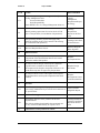
BID DATA SHEET
Clause
Reference
CC 1(b)(i)
ITB 5.1
ITB 7
ITB 11.1
ITB 12
ITB 13.1
ITB 13.2(b).
ITB 14
ITB17.1,17.2
&17.3
ITB 25
Name of Purchaser –RITES Ltd.
Contact person: Mr. S K Bhardwaj
JGM/IT, RITES Ltd
RITES Bhawan,
Plot No.1,Sector 29, Gurgaon
0124 - 2818309
Pre-bid Conference will be held on 26.04.2011 starting at 3 PM
in the Conference Room, 6th Floor, RITES Bhawan, Plot No.1,Sector 29,
Gurgaon
The bid, all correspondence and documents related to the bid shall be
in English.
Amount of Bid Security Rs. 6,00,000/- (Rupees Six lakhs)
Bid validity:
The bid shall be kept valid for a period of 120 (One hundred and Twenty)
days from the due date of submission of bid.
Number of copies: 1 original +1 copy
DO NOT OPEN BEFORE 15:00 Hours on 09.05.2011
Deadline for the submission of Bids is :
Time: 15:00 Hours
Date : 09.05.2011
In the manner specified in ITB 14
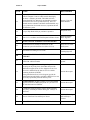
Venue/Address of correspondence:
GM/IT, RITES Ltd
3rd Floor, RITES Bhawan
Plot No.1,Sector 29, Gurgaon
Time, Date and Place of Opening of Bids:
Time: 16:00 Hours
Date: 09.05.2011
Place: 3rd Floor, RITES Bhawan, Plot No.1,Sector 29, Gurgaon
Office of the General Manager (IT) in the above mentioned address.
And in the manner as specified in the Request for Proposal (RFP).
Amount of Performance Security (Performance Bank Guarantee):
Ten percent of the Total Contract Price.
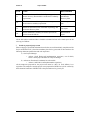
TABLE OF CONTENTS
SECTION I 1. 2. 3. 5. 6. BACKGROUND NOTE 1 Organization Current IT Systems in RITES Proposed SAP ERP system in RITES Ltd. Objectives of SAP Implementation Way Forward 1 2 2 3 3 SECTION II SCOPE OF WORK (SOW) 4 1. 2 3 4 5 6 7 General Scope Functional Scope Geographic Scope of the SAP system Number of Users Implementation methodology and use of tools Deliverables Profile of proposed project team SECTION III INSTRUCTIONS TO BIDDER 4 12 16 16 16 16 21 22 General 1 Qualification Requirements for the Bidders 2 Ethical Standard 3 Cost of Bidding 22 22 22 23 The Bidding Documents 4 Content of Bidding Documents 5 Clarification on Bidding Documents 6 Amendment of Bidding Documents 23 23 23 23 Preparation of Bids 7 Language of Bid 8 Documents Accompanying the Bid 9 Documents Establishing the Conformity 10 Bid Prices 11 Bid Security (EMD) 12 Period of Validity of Bid 23 23 23 25 26 26 27 Submission of Bids 13 Sealing and Marking of Bids 14 Deadline for Submission of Bids 15 Late Bids 16 Modification and Withdrawal of Bids 27 27 28 28 28 Bid Opening and Evaluation 17 Opening of Bids by Purchaser 18 Preliminary Examination of Bids 19 Evaluation and Comparison of Bids 20 Contacting the Purchaser 21 Award Criteria 22 Purchaser’s Right to Accept or reject any or all Bids 23 Letter of Award 24 Signing of Contract 25 Performance Security (Security Deposit – SD) 28 28 29 29 30 31 31 31 31 31 SECTION IV CONDITIONS OF THE CONTRACT (CC) 32 Contract and Interpretation 1 Definitions 2 Contract Documents 3 Interpretation 4 a) Governing Law 5 Settlement of Disputes 32 32 34 34 35 35 Subject Matter of Contract 6 Time for Commencement and Go-Live Acceptance 7 Contractor’s Responsibilities 8 Purchaser’s Responsibilities 36 36 36 36 Payment 9 Contract Price 10 Terms of Payment 11 Performance Securities 12 Taxes and Duties 37 37 37 40 41 Industrial and Intellectual Property 13 Intellectual Property Rights 14 Confidential Information 41 41 41 Development, Implementation, Go‐Live and Stabilization 15 Representatives 16 Project Plan 17 Design and Development 42 42 43 44 Guarantees and Liabilities 18 Time Guarantee & Liquidated Damages 19 Intellectual Property Rights Indemnity 45 45 45 Risk Distribution 20 Transfer of Ownership 21 Force Majeure 45 45 45 Change in Contract Elements 22 Changes to the “SAP” System 23 Prices for Services not covered in the Contract 24 Extension of Time 25 Termination 26 Assignment 27 Merger, Acquisition or Divestitures of the Contractor 46 46 47 48 48 50 50 Miscellaneous Clauses 28 Single currency conversion for bid evaluation 29 Insurance 30 Solvency of the Contractor 50 50 50 50 SECTION V 51 FORMS & ANNEXURES FORM # 1 FORM # 2 Profile of the Bidder Details of Projects Implemented 51 52 53 FORM # 3 FORM # 4 FORM # 5 FORM # 6 FORM # 7 FORM # 8 FORM # 9 FORM # 10 Ltd FORM # 11 Details of the Personnel to Be Deployed 54 CV of the Team Members 55 Deviations /Exclusions Schedule 56 Financial Bid Forwarding Letter 57 Price Schedule 59 Contract Agreement 61 Form of Bank Guarantees (Performance Security) 63 Confirmation from SAP with regard to their role in SAP implementation at RITES
65 Litigation History 66 ANNEXUREI TECHNICAL EVALUATION MATRIX FOR THE SELECTION OF IMPLEMENTATION PARTNER (IP) 67 ANNEXUREII SPECIFICATIONS FOR THE HARDWARE FOR DATA CENTRE
70 APPENDIXI BUSINESS PROCESSES OF RITES 190 APPENDIXII DETAILS OF LEGACY SYSTEMS 291 APPENDIXIII LIST OF OFFICE LOCATIONS OF RITES 294 APPENDIX IV CHECKLIST FOR THE BIDDER’S PROPOSAL 295 APPENDIX V SERVICE LEVEL AGREEMENT (SLA) 297 Section I
Section I
Background Note
BACKGROUND NOTE
1. Organization
RITES Ltd., a Government of India Enterprise was established in 1974, under the aegis of
Indian Railways. RITES Ltd. is incorporated in India as a Public Limited Company under the
Companies Act, 1956 and is governed by a Board of Directors which includes persons of
eminence from various sectors of engineering and management.
RITES Ltd., an ISO 2008 company, is a multi-disciplinary consultancy organization in the
fields of transport, infrastructure and related technologies. It provides a comprehensive array
of services under a single roof and believes n transfer of technology to client organizations. In
overseas projects, RITES Ltd. actively pursues and develops cooperative links with local
consultants / firms, as means of maximum utilization of local resources and as an effective
instrument of sharing its expertise. RITES Ltd. enjoys Mini Ratna Category-I status and is
one of the first Public Sector Enterprises (PSEs) to have achieved ISO 2000 Certification for
its entire range of services.
With work experience in more than sixty countries, RITES Ltd. is today established as a
leading Consultancy Organisation in the international arena and recognized by multi-lateral
funding agencies. RITES Ltd. now stands as one of the largest technical consulting firms in
India having presence in a wide range of sectors and offering a variety of services under a
single roof. RITES Ltd. clientele includes government agencies in India and abroad as well as
top industrial groups in the country.
Sectors of Operation
• Airport Engineering
• Architecture & Planning
• Bridge & Tunnel Engineering
• Constriction Project Management
• Electrical Engineering
• Environmental Engineering/ Urban Engineering
• Expotech
• Financial Management
• Geotechnology
• Highway Engineering
• Industrial Engineering
• Information Technology
• Marine Engineering
• Marketing & Client Services
• Materials System Management
• Operations Management
• Ports & Water Ways
• Privatizations
• Quality Assurance
• Railways
• Railway Electrification
• Rolling Stock Design
• Ropeways
1
Section I
•
•
•
•
•
•
Background Note
Signal and Telecom
Surveys
Training
Transport Planning and Economics
Urban Planning
Urban Transport
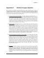
2. Current IT Systems in RITES
RITES Ltd. have a few fragmented stand-alone business application systems.
A list of the legacy systems working in different functions is given in Appendix II.
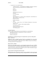
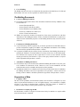
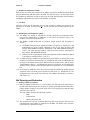
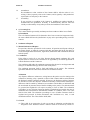
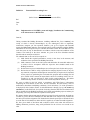
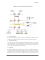
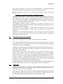
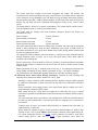
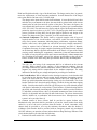
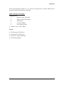
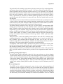
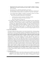
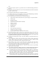
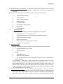
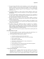
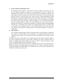
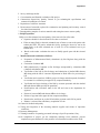
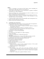
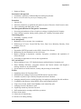
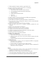
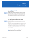
3. Proposed SAP ERP system in RITES Ltd.
SAP, being enterprise wide solution, offers an opportunity to integrate and optimize all
functions of the enterprise. The business objectives can be effectively met if standard SAP
system having best Industry practices is implemented. The IT strategy is based on
implementation of SAP system in RITES Ltd, integrated with other functional systems,
through this tender.
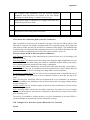
Proposed, “SAP system” at RITES Ltd. is indicated schematically in the following diagram.
Finance &
Controlling
Project
Manageme
nt
(PS)
Contracts &
Materials
Mgmt
(MM)
Marketing &
Business
Development
Quality
Mgmt
(QM)
Maintena
nce
Mgmt
Human
Resource
Managem
ent
Sales
&
Distri
butio
n)
-
System Integration
Enterprise Application Integration Layer
Legacy Systems
4. Product and Integration
The SAP ERP system should include the following minimum functionality:
• Finance, Accounts & Controlling
• Projects Management
• Human Resource Management, Payroll and Employee Self Service (ESS)
• Purchasing, Contracts and Materials Management
• Marketing & Business Development
• Sales & Distribution
• Maintenance Management
• Quality Management
Typical functionalities required in the SAP product are provided in Appendix-I.
2
Section I
Background Note
Enterprise Application Integration (EAI) layer will be used to integrate the SAP system with
legacy systems being retained.
(If any legacy system cannot be integrated with EAI layer the same will be connected on a
point-to-point basis with SAP system).
5. Objectives of SAP Implementation
Some of the objective expected to be achieved from the implementation of the SAP system at
RITES Ltd. are:
• Enable streamlining and automation of business processes
• Seamless integration between business functions on real time basis
• Ensure one-time data entry ensuring data consistency and reliability.
• Eliminate errors by improved checks and validations.
• Maintain audit trail and drilldowns to eliminate data redundancy.
• Implementing SAP enabled Best business practices & processes
• MIS Reports on Real Time Basis.
6. Way Forward
RITES plans to Go-Live of the Pilot Phase (Phase I) on “SAP system” named hereafter as
“SAP” with in a period of 9 months from the date of signing of the contract. The Roll out
Phase (Phase II) is expected to be completed in another 6 months from the Date of Pilot Phase
Go-Live. This tender aims to engage a SAP Implementation Partner for this purpose.
3
Section II
Scope of Work
Section II - SCOPE OF WORK (SOW)
1.
General Scope
RITES Ltd. expect the bidder to provide the following:
• SAP ERP System Implementation & Support (SAP implementation, Project
Management, Training, Support, Help Desk etc.)
• IT infrastructure (Data Centre setup, Servers, Hardware, etc.)
The SAP ERP software will be procured directly by RITES Ltd.
The scope of the work includes, but is not limited to, detailing of functionalities listed in this
tender document, understanding of RITES Ltd’s Business Processes, design and development
of implementation plan for both the Phase I and Phase II covering all the functions,
configuration and realization of the SAP solution, development of interfaces/ integration with
the legacy systems, testing, data migration/ porting, technical support, core team training,
functional and user training, final preparation, switch-over to the SAP solution, post “GoLive” support, setting up of competency centre, documentation, recommendation for technical
infrastructure, project management and monitoring. The bidder will be required to ensure
designing, configuring, testing and implementing all the functionalities/processes/modules
that are required to be implemented. The scope of work also includes program management,
change management, process improvement, solution assurance services and other services as
detailed in this document. Bidder is required to critically review the purpose of
implementation and shall ensure inclusion of all other essential services (not mentioned
specifically) for achieving the objective within the time frame for successful implementation.
1.1 Scope of Work (SOW) for the IP
The general scope of the proposed system is as follows:
The IP shall be required to do the following:
A) SAP ERP System Implementation
I. Design and develop the Project Plan
The detailed project plan of the implementation is to be prepared at the commencement of the
project. The implementation of SAP solution will require a strong program management
activity integrating the core product implementation with software application. This ensures
complete acceptability of the solution within the organization.
Program management services shall aim at constantly improving the business processes,
leveraging technology solutions, incorporating best-of-breed industry practices to maximize
opportunities for RITES Ltd.’s business operations and at the same time addressing growth
and development of the employees.
II. Develop detailed scope for the functionalities to be implemented
The detailed scoping of the business processes to be implemented has to be finalized by IP in
association with the project team members from RITES Ltd.
III. Deployment of IP Manpower
IP should ensure deployment of sufficient specialised and experienced man power throughout
the project to complete the implementation & stabilisation of the System in time successfully.
4
Section II
Scope of Work
IV. Detailed Design
IP has to design the relevant business processes with all details. This effort shall have the
following important tasks:
• AS-IS process mapping to activity/ task level and current state analysis to identify
areas of improvement and opportunities for standardization.
• Review the AS-IS processes and define the TO-BE processes that are based on
business requirements, GAP Analysis and SAP enabled “best practices” and
processes.
• Designing of the specific screens and data formats along with the process and method
for entering the details.
V. Configuration
Based on the functionalities designed, IP shall be responsible for:
• Configuring the SAP system according to the processes
• Integration of the detailed design across modules
• Testing of configuration of Modules
• Identification of the fields that need to be captured for the Masters and mapping of
the information with the legacy systems
The design proposed by IP, shall be realistic, simple, flexible enough to take care of future
changes in the organizational structure and easy maintainability.
VI. Developments and Interface management with legacy systems
Developments shall be in the nature of enhancements to existing applications, additional
applications, additional reports, and form changes.
Interfaces/ Integration will be to existing legacy systems or to additional standalone/ new
applications. These interfaces may be interim (during the course of the project) or permanent
(extending beyond the project) in nature. IP shall validate and confirm the need for any such
developments/ interfaces that are required in order to meet the functionality of modules.
Following tasks are to be undertaken by IP with the assistance of RITES’s Core Team:
• Prepare a fitment analysis to identify enhancements that are required because of
business requirements and which cannot be met from standard SAP functionality or
through workaround
• Identify the interfaces that will be required to be developed
• Study the structure of the legacy data systems w.r.t. SAP product with a view to
identify enhancement, development, interface, and reporting requirements.
• Documenting the functional specifications for enhancement, development, interface
and reporting requirements (e.g., Layout sets, daily status reports, reconciliation
reports etc), based on inputs
• Prioritization of the development efforts and estimates for reporting / enhancement
requirements.
• IP shall develop detailed technical design documents for all such development
requirements including any data operation and security issues
• Assisting in data migration, Checking data quality and integrity
• Testing of developments/interfaces
the
procedures
for
implementing
and
maintaining
the
• Document
temporary/permanent interfaces, developments and enhancements.
• Data porting / uploading into the SAP system.
5
Section II
Scope of Work
VII. Integration Management And Testing
Integration management and testing should be as per the standard practices. This shall include
development of exhaustive test scenarios, carrying out the integration tests on these scenarios
and necessary corrections based on test results and the feedback. IP shall be responsible for
completing the integration tests with the desired quality and schedule.
RITES shall provide full support to IP in this connection. RITES and IP project team shall
jointly envisage scenarios for testing and developing test scripts. RITES will also make
available live data for the purposes of testing wherever required. RITES, IP and Quality
Review group shall extensively participate in the module and integration testing. IP shall be
responsible for the documentation of integration process & test results. The Quality Review
Group proposed to be formed at RITES shall comprise representatives of RITES, SAP,
Implementation Partner and the Consultant of RITES.
The data conversion testing shall also be done in similar manner to ensure that, after the
loading of final data, the system remains stable.
VIII. Data Migration
All specifications that are needed to populate the data into the new ERP system need to be
defined.
IP’s responsibility for Data Migration
This shall include the following tasks:
Identification & development of the data upload/download programs
Providing data migration tools and templates to RITES
Populate and migrate all the legacy/ raw/new data element to the SAP system
Training and facilitating the RITES core team
Assistance in Checking data quality and Integrity
Integration testing of the configured system using the populated master and
transaction data
Assist RITES team in Master Data management
The following data need to be migrated:
All open transactions and all transactions from the start of financial year of GoLive.
Standing or master data such as vendors/suppliers, customers, all employees,
material, work breakdown structures, equipment, work specification, cost data,
etc.
Transactional data for all live projects of RITES. The live project data to be
populated based on the agreed TO-BE process requirement.
All the related Master Data and associated drawings, test results etc. as
applicable
IP’s responsibility shall be to ensure that data migration is complete in all aspects, within time
so that the requirements of the implementation are fulfilled.
RITES Ltd.’s responsibility for Data Migration
RITES Ltd. shall cleanse, rationalize and validate the data with Bidders assistance.
6
Section II
Scope of Work
IX. Technical Support
IP is required to undertake the following:
a) Formulation of all policies and procedures related to Basis technology, System
Administration, Data Base Management, applications, archives, network management
& security, back up etc.
b) Prepare requisite system landscape and procedures for smoothly implementing SAP.
This shall also take into consideration the phased pilots and rollouts.
c) IP shall assist the RITES team to perform all authorization-related activities (activity
group, authorizations, profiles, etc) till the SAP system stabilizes.
d) Assist RITES to manage the legacy data interfaces, print spools, batch Jobs, printer
configuration etc.
e) Prepare a detailed System administration manual, Data administration manual,
operational manual, User manual which shall be used by RITES employees to run
SAP enabled production environment. This shall also include how the various
parameters shall be monitored/ tuned in a live system.
f) Finalize the archival policies for all the functional areas. All necessary configurations
shall be done and tested.
g) Prepare requisite system configuration for disaster recovery management and Fail
Over system plan.
h) Round the clock support for trouble shooting in functional and technical area
X. Training
IP shall conduct a training need assessment of RITES Ltd.’s SAP core team members as well
as end-users as a component of the process improvement and change management process.
Training needs should be continuously refined and frequently reconfirmed with the end-user
community & the core team as the project progresses.
Training tools and Training materials:
Use of recommended SAP training tools / software(s) for providing various training is
essential. Adequate training material which includes training manuals, quick reference cards
etc should be provided during the training sessions. The recommended training material
should be in paper & electronic media with courses on SAP fundamentals, business process
overview, job activity training, and delivery options being on-line, instructor led class rooms,
etc.
Core Team Training
This is the training for the SAP core team of RITES Ltd. for SAP implementation. This core
team of RITES Ltd. will comprise of members from all the business functions and IT. This
training should enable the SAP core team of RITES Ltd. for setting up of SAP Competency
Centre and to involve in implementation, building and managing SAP related skills and
maintain the SAP system in RITES Ltd.
The training should be given to approximately 40 personnel of RITES Ltd. by IP themselves,
at the cost of IP at RITES Ltd. The quality of the training should be equivalent to SAP
certification training based on standard SAP certification training material.
End User Training
7
Section II
Scope of Work
All the end users need to be trained for the smooth functioning on SAP System. The IP shall
submit a detailed Training Plan for all the end users.
XI. Final Preparation and Go-Live
IP is required to undertake the following at the purchasers premise:
• Review readiness for cut over
• Manning the central help desk for any queries
• Resolve Technical & functionality related issues for SAP
• Define the requirements towards the phasing out of the legacy systems
• Review the usage and performance of the SAP system till it stabilizes
• Maintaining the interface between legacy system and SAP during transition
• Interfacing with the proposed UCS & existing Legacy Systems to be retained.
• Documentation of the issues/problems that come up and solutions thereof.
• Final configuration/ integration, volume and stress testing
• Data migration
• Switch over to production environment.
XII. Post Go Live Support
(a) Stabilization support
IP shall be responsible for Project implementation and correct & satisfactory functioning of
the SAP system. IP shall provide post – implementation support to the purchaser to ensure
the efficient day-to-day functioning of the SAP system for a period of three months from the
date of Go-Live at all the locations of RITES Ltd. Atleast two persons from each function and
two persons from each technical area like ABAP, Basis etc. should be there on site during
stabilization period. In addition, IP shall extend their support during the 1st quarterly, half
yearly, nine monthly and annual closing (for 10-15 days for each).
(b) Extended support
In addition to (a) above, IP is required to provide extended support for 1 year from the end of
stabilization support period at a price to be quoted in the financial bid. During this period, IP
shall ensure trouble free running of the total system.
Additionally, the IP is required to provide handholding support for another 1 year at the
discretion of the purchaser with the same price and terms & conditions of the contract as that
of extended support.
For smooth running of the system & day-to-day functioning it is of paramount importance
that adequate transfer of knowledge to the core team members of RITES takes place. Towards
this, the IP should mentor a group of core team members who will be responsible for doing
any configuration change independently.
IP needs to take the responsibility of creating post-go-live support strategy. The objective of
this exercise is to ensure that RITES Ltd. builds in-house competencies to maintain the SAP
solution in the long term without dependency on external consultants.
XIII. Documentation
8
Section II
Scope of Work
IP shall ensure preparation of complete documentation of all configuration settings, other
activities, steps / stages involved in the implementation with the support of the Core team.
IP in close coordination with RITES Ltd. core team shall prepare the business process
document, end-user manuals and training documents in the jointly agreed templates. Three
(3) sets of hard copies along with three (3) sets of softcopies in CD/DVD of each of the
finalised documents shall be submitted to RITES Ltd.
XIV. Technical Architecture
IP shall validate RITES Ltd’s existing technical infrastructure and recommend an
appropriate solution to meet RITES Ltd’s business requirements in the implementation of
the SAP system. IP shall also monitor the archiving strategy, control and security aspects
during implementation at RITES Ltd.
IP will then recommend the IT architecture design including hardware, and operating
system for the implementation keeping in view the geographical spread & complexity of the
implementation, communication infrastructure available in the country & at RITES Ltd. and
Data Archival & Storage requirements. The recommended architecture shall also provide
for scalability, disaster recovery, test and production environments. IP shall assist in
providing detailed specifications for the sizing of hardware to be procured by RITES Ltd.
IP shall also validate the hardware configuration to be procured by RITES Ltd.
XV. Sign Off And Closure
RITES Ltd. recognizes the importance of an expeditious sign off and closure of agreed
deliverables and RITES Ltd. Team will expedite the process of sign off and closure.
However, IP shall facilitate such acceptance/sign off from the Management/Process owners
for all the deliverables mentioned above by way of preparing / producing such
documentation / review reports / test results etc. as may be necessary for RITES Ltd. to
ascertain that the prerequisites to subject sign off and closure have been met completely in
accordance of the Contract Document.
XVI. Solution Assurance by Quality Review Group
The SAP implementation at RITES Ltd. is to be monitored by the Quality Review Group for
ensuring smooth and timely implementation as per the requirement of the purchaser. IP shall
provide details of the Quality Assurance Plan envisaged for the implementation of SAP
system in the project plan. RITES Ltd. requires that all the deliverables forming part of the
whole implementation process including broadly the Implementation Strategy, Business
Analysis, Readiness Assessment and Go Live Review etc. will be subjected to stage- wise
Quality Audit by Quality Review Group. The Quality Review Group shall comprise
representatives of RITES Ltd, Consultants of RITES Ltd, ERP OEM (SAP) and the
Implementation Partner.
The Quality Review Group shall be responsible for:
•
Communicating the project status & risk to top management
•
Establish Project Standards, Methodologies & Tools
•
Participate in Steering Committee meetings
•
Drive Quality Review process
•
Prepare Quality Review Strategy & Plan
•
Review Business Blueprinting prepared by Bidder
•
Review SAP system Go live readiness
•
Review SAP system stabilization.
9
Section II
Scope of Work
B) Supply of Hardware
Data Centre: IP shall construct the Data Centre for ERP, size, supply, install, configure and
maintain the server hardware required for the SAP ERP system, including supply of necessary
systems software such as Server Operating System, anti virus etc., provide perpetual software
licenses, user and administration manuals, software upgrades, maintenance, patches and
warranties and provide on-site support for the data centre, for the entire period of the contract
The IP shall assist RITES Ltd in setting up the data centre.
1.2 Organization Change Management
The purpose of Organization Change Management is to ensure that RITES Ltd. achieves the
expected results from its investment in SAP technology in a short span of time. As part of this
service, IP will work closely with RITES Ltd. core team in introducing the change-processes,
stressing the importance of organizational alignment, and introducing the necessary tools and
techniques needed to address issues in the Organization.
1.3 Process Improvement
Process Improvement will be done to enable RITES Ltd. to adopt some of the best practices
embedded in the SAP system systems. The areas that can bring maximum benefits will be
identified by IP in close coordination with RITES Ltd. process owners. The consulting IP team
needs to work closely with the user team to translate this into a set of processes that can be
implemented in SAP. In order to do this, IP will also bring in knowledge of the best practices
adopted by other world-class organization to the RITES Ltd. implementation.
IP shall associate in identifying KPI’s for RITES Ltd. and share benchmark data with RITES
Ltd. team so that their relevance in terms of best practices in the industry can also be
ascertained. This in turn will help the implementation team to set up these KPIs in the system.
The KPI’s relevant to RITES Ltd. will thus be identified and made to report through BW of
the SAP system.
RITES Ltd. envisages that the proposed process improvement and process re-engineering is
SAP-enabled. This will enable early completion of the implementation and will also avoid any
major re-work. Accordingly process improvement exercise will be an integral part of
implementation and the project plan for the same will be dovetailed as part of the overall SAP
implementation plan.
1.4 KPI Measurement & Monitoring
The Key Performance Indicators (KPIs) shall enable RITES Ltd. to measure, analyze and
improve the business processes and performance within the enterprise. KPIs shall enable
comparing performance data from RITES Ltd. with industry benchmarks, which in turn shall
help in defining new goals for enhancing performances. This substructure shall be created for
enabling RITES Ltd. to optimize the processes by combining key data from KPIs with
information on how the business processes affect these KPIs.
The measurement of KPI’s will be done using the standard reports in various modules and the
SAP Business Information Warehouse (SAP BW) system. The scope of work shall also
include configuring the SAP BW system to meet the reporting and measurement parameters
specific to RITES’s business requirements.
1.5
Quality Review and Audit by the ERP OEM (SAP)
The SAP implementation at RITES is to be audited / reviewed on continuous basis by the
ERP OEM (SAP) for ensuring proper, smooth and timely implementation as per the
10
Section II
Scope of Work
requirement of RITES. The cost involved in the above is to be borne by the Bidder and
included in their Price Bid. RITES shall directly pay the ERP OEM (SAP) against their
invoice to be routed through the Bidder’s Project Manager and such payment to the ERP
OEM (SAP) will be deemed to be made to the Bidder and limited to the total payment due to
the Bidder up to the completed milestone.
The ERP OEM (SAP) will depute one Senior Manager for atleast 5 days each during
Blueprint & Go-Live phase on mutually agreed days at RITES site for ensuring smooth,
proper and timely implementation of the SAP system at RITES. Also representatives from the
ERP OEM (SAP) will be members of the Steering Committee to be formed at RITES for the
constant review and monitoring of the SAP implementation at RITES. The feedback provided
by the ERP OEM (SAP) has to be incorporated by the Bidder at no additional cost.
The envisaged responsibilities of the ERP OEM (SAP) for the SAP implementation project at
RITES are as follows:
Monitor and Review Quality of Project’s Progress
i) Review Business Blueprinting prepared by the Bidder
ii) Prepare Quality Review Reports in the following areas:
a) Solution Review
b) Technology Review
c) Development Review
iii) Suggest Review recommendations and Update Steering Committee
iv) Periodic Review of Project Status, Plans and Progress
v) Review Go-Live parameters/ readiness for the SAP implementation
vi) Participate in Steering Committee meetings and select project meetings
vii) Review the SAP Stabilization at all the locations of RITES
viii) Establish effective issue reporting and resolution structure
The ERP OEM (SAP) shall perform Audit Service as per the scope of work specified in the
tender document and submit Audit report/Audit observations on the SAP implementation to
the Steering Committee from time to time including two audit reports/observations to be
submitted, one after the Business Blue Print and the other before the Pilot Go-Live of the SAP
system.
(The Bidders will have to submit a confirmation with regard to above, from SAP on their
Letter head signed by their Authorized signatory, as per format given at FORM #10 and
enclosed with the Technical Bid Part – I).
1.6
Knowledge Transfer & Training
RITES believes that it needs to build in-house skills in SAP implementation that will enable
RITES to reduce the dependency on external skills. The implementation approach followed
by IP has to be such that it ensures that there is significant knowledge transfer from
consulting team to the RITES Core Team during the course of implementation. This coupled
with the emphasis on the product and implementation training offered to user teams before
starting the project ensures that the required platform for knowledge transfer is established. IP
shall impart user’s training.
RITES understand that for a project of this magnitude, appropriate & well-designed training
for the core implementation team is a critical success factor. A well-designed training strategy
is vital for development of competency that would enable RITES’s core project team to steer
the SAP implementation program through out the organization. IP shall therefore prepare a
plan for suitable training needs of RITES’s project core team members that would help them
understand the SAP system in detail and subsequently undertake the SAP implementation.
11
Section II
1.7
Scope of Work
Project Management Guidelines
a) The project will be governed by a Steering Committee that consists of members
appointed by RITES, member(s) of IP and Quality Review group. RITES will
approve the constitution of Steering Committee at the commencement of the project.
b) IP shall be responsible for “go-live” as per the agreed schedule and output from the
deliverables in each Phase.
c) RITES shall appoint a Project Management team (PMT) who shall co-manage the
project together with the Project Manager appointed by IP and drive the project to
successful completion.
d) IP, in coordination with RITES’s PMT, shall execute the detailed
design/configuration/testing and all other aspects of implementation.
e) Deployment of resources by IP in the project is subject to acceptance of the quality of
such resources by RITES. For any replacement / addition of resources, IP shall give
four weeks advance notice to RITES.
Further, during the course of the project, if RITES finds any resource unsuitable, they
shall have the right to de-list the resource from the project after due deliberations with
IP immediately and providing one month time for appropriate replacements.
f) All the deliverables of IP will be subjected to quality review under Solution
Assurance by Quality Review group.
g) In all the activities of implementation, IP’s Project Team shall bring in expert Inputs
and guide the project. The RITES’s Project Team shall actively participate along with
IP in carrying out required activities.
2 Functional Scope
2.1
SAP ERP system will broadly cover the following prime functions of RITES
Ltd.
(Typical functionalities required in the SAP product are given in Appendix-I; below
mentioned list is Indicative & not exhaustive)
• Finance, Accounting and Controlling
General Ledger
Accounts Receivable
Accounts Payable
Payments and Reconciliation
Costing
Budgeting
Assets accounting
Assets Leasing
Taxation, duties and levies
E-payment and E-receipts
Banking & Treasury
Risk Management
Investments & FD
Fund Management
Contract Accounting
Export/ Import Management
Audit Trail
PF Administration
MIS
12
Section II
Scope of Work
•
Project Management for Consultancy projects & Other than consultancy projects like
– Export, Lease, Inspection, Operation and management, Project Management,
Privatization and Concession, Training and capacity building, Procurement services –
Material System Management, EPC – Turnkey, Quality Assurance Services
Pre-Project planning involving project identification, Project manpower
Utilisation feasibility studies and project appraisal
Project support activities comprising surveys, environmental and social
impact assessment, geo-technical and other investigations Project preparation activities of detailed engineering, design, tender
documentation, bid evaluation, Vendor selection, construction management
(Deposit Works and EPC- Procurement of material, selection of construction
agency, client’s fund management, contractor’s bills, measurement books etc)
Project implementation/ Payment to contractors, management covering
contract administration, field engineering and construction supervision,
procurement services, product certification, quality assurance.
Design and development of rolling stock
Operation and Maintenance - Commissioning, operation, maintenance,
rehabilitation of rolling stock and workshop management.
Quality assurance and management, third party inspection, In-house
Laboratory Testing, technical audit Certification Assistance for management
Systems in ISO 9001, ISO 14001, ISO 22000, OHSAS 18001 etc including
relevant training.
Multimodal Transport studies.
Materials supply management- Procurement and Logistics Management
consultancy services for the projects funded by bilateral and multilateral
funding (World Bank, ADB etc.) agencies as well as those funded by local
Government
Conduct structured training and development programs for personnel of all
categories and disciplines.
Financial, business plan, advisory services (P&C)
Design, development and implementation of information system
Export and Lease -Supply, leasing, rehabilitation, commissioning of
locomotives and rolling stock, spares and subassemblies and allied services.
Sizing, Selection, Supply, Commissioning, rehabilitation and leasing of
Railway Rolling Stock including Inventory, Billing etc.
Economic and financial evaluation
Other Areas like Domain Training, Management Consultancy, etc.
•
Human Resource Management, Payroll and Employee Self Service (ESS)
Employee Database
Recruitment
Training and Development
Employee separation
Manpower planning
Promotions (Performance Appraisals)
DAR (Disciplinary Action Rules) & Vigilance
13
Section II
Scope of Work
Medical facilities
Grievance Redressal
Employee Transfer & Postings
Employee Leave Accounting
Staff Advances
Time Management (Attendance system)
Misc. staff bill processing
Self/ Company leasing
Retirement/ Resignation/ Termination and Death Cases
Payroll
•
Purchasing, Contracts and Materials Management
Indenting
Sourcing
Tendering
Placement of Order (P.O.)
Post Order Placement Activities
Inspection
Inventory Management
Consignment Management
Procurement of services
•
Marketing and Business Development functions
Business Development activities
Client information management
Tendering
•
Sales and Distribution
Sales Management
Trading functions
Distribution of Loco’s etc to overseas clients
•
Maintenance Management
Maintenance planning & scheduling
Maintenance work order processing- (from notification to completion)
Spare parts management
Outsourcing jobs through contractual resources
Maintenance document management like drawings, standard maintenance
practices, Safety manuals, maintenance manuals, reports
Maintenance history & analysis
Maintenance budgeting & costing
•
Quality Inspection Management
Quality inspection and monitoring
14
Section II
•
Scope of Work
Corporate Services and Administration
Company Secretary - Correspondence with Ministry, Meetings, Parliament
queries, VIP references & other works of co-ordination section
Library
Hindi Cell
Legal Cell
Marketing and Client Services
Insurance
Air ticket bookings
Stationery
AMC, Maintenance of contracts, Facility management and maintenance of
RITES Building, Guest House, Flats
Dispatch & courier
Welfare and canteen
• Others
IT Centre – AMC Services for IT Hardware Maintenance, Procurement,
Internet services
ISO Division – Compliance of ISO standard in RITES
Internal Email System
Management Information System
File Tracking System
2.2 Other Functions
In order to support the prime functions, the SAP should also cover the following:
- Dash Board functionality (including Business Analytics and BI tools)
- Document Management
- Workflow Management
RITES Ltd have envisaged prioritizing the overall functional scope into two main phases:
Phase I - Pilot Phase
RITES Ltd. wishes to implement all the functions as mentioned above to the entire
organization in the Pilot Phase comprising of the Corporate Office at two locations in
Gurgaon, One Regional Office at Delhi and One Office at Kolkata. This phase must attain golive latest by the end of 9th month from start.
Phase II - Roll - out Phase
Roll-Out sites shall address the Go-Live of the remaining locations/ offices/ sites of RITES
Ltd. The roll-out of all the remaining locations should be completed by 6 months. The price
for the Roll-Out Phase as quoted in this tender shall remain valid till 3 years from the date of
submission of this bid. Apart from this, IP shall also provide 3 months of stabilization support
after the Go-Live at all the locations of RITES.
Legacy Systems to be integrated with SAP system
Brief description of all existing legacy systems is given in Appendix II. All the systems will
be integrated with SAP system using EAI layer. Integration will be done using standard
15
Section II
Scope of Work
connectors as appropriate to the SAP system and the legacy systems. However, some of the
legacy systems may have to be connected to SAP system on point-to-point basis where they
are not compatible with EAI software. During implementation, number of touch points of
each system may increase or decrease. Also if all the functionalities of an existing legacy
system are covered in SAP, then that system will be shifted to SAP.
3 Geographic Scope of the SAP system
The Geographic scope of the implementation of the SAP system shall be RITES Ltd.
establishment at Gurgaon Office & all other offices/locations of RITES Ltd.
A list of the present location consisting of the Corporate Office, Gurgaon alongwith other
Regional Offices is provided in Appendix III. The geographical scope for implementation can
be extended if any new office/site comes up in RITES Ltd. during the implementation phase.
Also, provision is required to be kept under the SAP Implementation project to include new
project site envisaged in the future.
4
Number of Users
Estimated number of users of the SAP system has been initially assessed at 200 named users
which may go upto 500 named users. Apart from that 2,500 ESS users and 2,500 payroll users
are required for RITES. Decision regarding the distribution of SAP licenses to various
locations within RITES Ltd. will be at discretion of the purchaser.
5
Implementation methodology and use of tools
During the SAP Implementation Process, the methodology used should be a proven and
repeatable process and should be based on ASAP methodology. Implementation Partners
should have extensive previous experience in use of ASAP methodology tools like SAP
Solution Manager and make extensive use of them for accelerated implementation and
minimise risks.
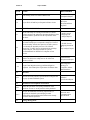
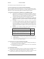
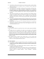
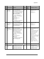
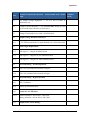
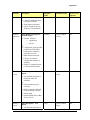
6
Deliverables
IP shall be required to follow milestone based deliverables for the SAP Implementation
process. The methodology, detailed project activities, deliverables and responsibilities, which
are to be followed during implementation are given as below.
Sl. N0
SCOPE
1.0
PROJECT PREPARATION
1.1
The IP shall submit detailed Project Plan and get it
finalized in accordance with the clause no. 16 of the
Conditions of Contract
1.2
The IP shall study the Scope of the work, in particular the
Functionality Requirement Specifications, Technical
Requirements and give their observations/understanding of
the total work, resource commitment and elaborating
broadly on the development proposed to be taken up
through customisation/third party tool/bespoke
development
DELIVERABLE
Agreed And
Finalized Project
Plan
Inception Report
16
Section II
Scope of Work
Sl. N0
SCOPE
DELIVERABLE
1.3
SAP training for the core team of RITES Ltd.
Core Team Training
Completion Report
1.4
Project Kick Off and Project Preparation Phase closure
Team Mobilization
& Project
Preparation Phase
Sign Off
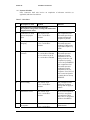
2.0
BUSINESS BLUEPRINT
2.1
The IP shall study the existing functionalities of all the
business processes & submit the document detailing at least
the functionalities, problem areas & expectations of the
purchaser
2.2
After analysing performance of the “AS-IS” processes,
the bidder shall prepare a comparative analysis of each of
the functionality with the best practices of SAP system so
as to identify the desirable processes. He will then
prepare the “TO-BE” Process document along with Gap
Analysis Report, which will include his specific
recommendations for RITES Ltd.’s adoption of new
process
“AS-IS” process
Mapping And
Analysis Report
“TO-BE” Process
Mapping Document
&
Gap Analysis Report
2.3
Freezing of customisation requirement after the purchaser
finalizes its decision to adopt some or all of the best
practices of SAP
Customization
Requirement Report
2.4
Prepare Data Migration strategy and Data Migration
templates. Also identify the requirements for Master Data
Data Migration
Strategy &
Templates, Master
Data Structures
2.5
2.5.1
2.6
Interfaces
Provide necessary interface specifications to integrate the
Legacy Systems with SAP system.
Installation of development environment
2.6.1
Assist the purchaser in accepting installation of the
hardware servers etc. at the premises of the purchaser.
2.6.2
Prepare the additional networking requirements (if
required) for the SAP system keeping in mind
Networking and Communication infrastructure already
available with the purchaser.
2.7
Legacy System
Interface
specification Report
Network And
Communication
Specification
Change Management
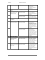
17
Section II
Sl. N0
Scope of Work
SCOPE
DELIVERABLE
Prepare change management strategy and identify the
Change Management issues
Processes/Procedure
Roles/Responsibility
Assist RITES Ltd. in it’s Change Management initiatives.
Change
Management
Requirement Report
& strategy
2.8
Identify training requirement for various levels of End
users of the purchaser (in consultation with purchaser).
Training
Requirement
Report for the End
users
2.9
Design training modules, prepare and supply study
materials including audio-visual contents of the training
(In consultation with purchaser).
Training Curriculum
for the End users
2.10
Business Blueprint Phase closure
Business Blueprint
Phase Sign Off
3.0
REALIZATION
3.1
The IP shall identify, design and develop those
components of the functionalities that are not covered
within the standard SAP product.
Bespoke
Development Plan
3.2
IP shall provide the design of the bespoke component
together with its schedule for development. The
development of the bespoke component will however be
under taken only after its approval by the purchaser.
Bespoke Design
Documents
2.7.1
3.3
IP shall provide the source code together with complete
documentation for such bespoke component of the SAP
solution.
3.4
Interfaces
3.4.1
IP shall integrate the specified legacy systems with SAP
system using standard EAI layer software and connectors as
per specifications.
3.5
End User Training
3.5.1
3.6
Train all the end users of the purchaser in the SAP
implementation.
The end user training should enable the operational user
to carry out his/her functionality in respective area.
Bespoke
Development Source
code Documentation
Legacy Systems
Integration Report
Training schedule &
Training Completion
Report for the End
users
Authorisation security and access control
18
Section II
Scope of Work
Sl. N0
SCOPE
DELIVERABLE
3.6.1
IP shall assist RITES in formulating appropriate security/
authorization, control policy to prevent unauthorized access
to programs, data, screens and outputs.
Authorization,
Security And Access
Control
Specification
3.6.2
Shall build the prescribed access right & control
mechanism into the SAP system.
Demonstration
Report
3.7
Integration Testing
3.7.1
IP shall plan and carry out comprehensive tests of all the
modules and carry out corrections based on test results and
feed back. Quality Review group shall be involved in
testing of each module and sub module and requisite
interfaces. IP shall simulate full load and stress test.
Unit test report,
Integration test
report, Full Load &
Stress Test Report,
User Acceptance
Test Report and Sign
Off
3.8
Realization Phase closure
Realization Phase
Sign Off
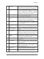
4.0
FINAL PREPARATION
4.1
Audit and Quality Control
4.1.1
IP shall submit the standard parameters for auditing and
quality control of the system to be provided by SAP and
demonstrate their effectiveness to the Quality review group.
4.2
Quality Audit
acceptance
Data Migration
4.2.1
IP shall extract, transform & load/ migrate the data from the
legacy systems and other electronic data of the required
period as specified by RITES to the SAP system
Data Migration
Completion report
4.2.2
Extract the data from the legacy systems as per the Cut Over
strategy into the format as required by the SAP system
Functional
Specifications for
Upload programs
4.3
If, for reasons entirely attributable to IP, the SAP based
system does not conform to the Scope of the Work or does
not conform to all other aspects of the Contract, the bidder
shall at its cost and expense make such changes,
modifications, and/or additions to the system as may be
necessary to conform to the Scope of Work and meet all
functional and performance standards.
Action taken Report
4.4
Assist the purchaser for setting up SAP competency
centre
Technical support
19
Section II
Scope of Work
Sl. N0
SCOPE
DELIVERABLE
4.5
Prepare System Manual in adequate detail for use in the
Central Computer Centre to enable trouble shooting by
purchaser’s software personnel. The bidder will also
prepare detailed User Manual for each module to enable
the field level user to use system effectively. The User
Manual must be exhaustive and shall contain detailed, step
by step instruction for smooth access to, operations in and
exit from the system.
System, User and
other Manuals
4.6
Set up a Help Desk facility at purchaser’s premises
4.7
Pilot Go Live readiness and Final Preparation Phase closure
5.0
PILOT GO-LIVE AND POST GO LIVE SUPPORT
5.1
Commencement of commercial transaction on the
production system for the Pilot sites (Pilot Go-Live)
Pilot Go Live of the
SAP system
5.2
Customisation Training to Core Team
Customisation
Training Sign Off
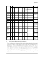
6.0
ROLL-OUT OF THE SAP SYSTEM AND EXTENDED
SUPPORT
6.1
Roll-out of the SAP system to all the remaining locations of
RITES Ltd. within 6 months
Roll-out of the SAP
system
6.2
Post Go-live Support: For attending to the problems
occurring on day to day basis, the bidder shall provide
stabilization support (Post Go-live Support) on-site for a
period of 3 months from the date of Go-live at all the
remaining locations of RITES.
During stabilisation (Post Go-live Support) period, the
implementation team shall be available at RITES to sort out
day-to-day operational problems that may arise.
Action taken report
6.3
Extended Support: IP shall continue to provide Extended
support on site for an additional period of 1 year after rollout at all the locations of RITES.
Action taken report
6.4
In addition IP shall extend their support during quarterly,
half yearly, 9 monthly & annual closing (for 07 days in
each case).
Action taken report
6.5
Closure of the Issue List and Project Closure
Roll-Out Phase Sign
Off and Project
Closure
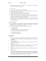
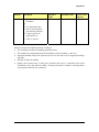
7.0
DISASTER RECOVERY AND BACK-UP POLICY
Help desk setup
Final Preparation
Phase Sign Off
20
Section II
Scope of Work
Sl. N0
SCOPE
DELIVERABLE
7.1
IP shall formulate an effective Back-Up strategy and
Disaster Recovery Plan and advice on Business Continuity
Requirements.
Back Up Strategy
And Disaster
Recovery Plan
7.2
IP shall formulate an effective plan for failover system to
ensure business continuity requirement.
Fail over system
plan
7.3
IP shall test the effectiveness of the Back Up Strategy and
the Disaster Recovery Plan.
Test report
7.4
IP shall demonstrate continuity of business processes &
activities from the DR site.
Demonstration
report
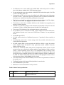
All the deliverables mentioned above should be submitted at least in five hard copies & one
soft copy in CD-Rom.
7
Profile of proposed project team
IP has to deploy a specialised and trained team for the successful and timely completion of the
Project at RITES Ltd. It is therefore mandatory that the key personnel in the team have the
following minimum qualification and work experience.
a) One Project Manager
• Atleast 2 SAP End-to-end implementation experience, out of which,
atleast 1 SAP project should be as a Project Manager.
b) Atleast two Functional Consultants for each module
• Atleast 1 SAP End-to-end implementation experience.
All the manpower proposed for the project team must be a B.E./ B. Tech/ MBA/ CA or
equivalent. The manpower and the project team proposed for RITES Ltd. will be verified by
the Evaluation Committee of RITES Ltd. at the presentation to be given by IP.
21
Section III
Section III
Instructions to Bidder
INSTRUCTIONS TO BIDDER
General
1 Qualification Requirements for the Bidders
This bidding process is open to SAP certified Implementation Partners (IP) with successful
implementation of SAP system across the world having:
(i) An average annual turnover of minimum Rs. 200 Crores from their Software Service
Business in the last 3 financial years in India (Copy of Audited Balance Sheets for
last 3 financial years to be provided) and
(ii) Should have experience of atleast one SAP ERP project* as a prime Implementation
Partner/ Program Management Consultant in PSU / Govt. Sector in India (Project
completion certificate from Client & Other Documentary evidences) and
(iii) Should have SEI CMM Level 3 or higher level certification. In case, the certificate
for SEI CMM Level 3 or higher level certification expired, then the Assessment
certificate for further regularization or upgradation of SEI CMM Level 3 or it’s
higher level need to be submitted (Copy of SEI CMM Level 3 or higher level
certification or Assessment certificate for further regularization or upgradation need
to be provided) and
(iv) The IP must have atleast 200 SAP Functional Consultants as on 31st Dec, 2010 on the
roll’s of the Company in India (Certificate by the CEO/ Head of the Company/
External Auditor need to be provided).
* For a project, to qualify as a SAP ERP project, please refer to the definition of SAP ERP
project at Annexure I.
Subsequent sub letting / offloading of full or part of the work and supply of 3rd party software,
unless otherwise specified in the contract or with due permission by the purchaser, will not be
allowed. No bidding through Consortium will be allowed.
The bidders must familiarize themselves with local conditions and take these into account
while preparing their proposals. To facilitate the bidders in making the proposal, the client can
be contacted at the address given in the Bid Data Sheet.
2 Ethical Standard
Bidders are expected to observe the highest standard of ethics during the procurement and
execution of this Contract. In pursuit of this policy, the Purchaser will reject a proposal for
award if it determines that the Bidder being considered for award has engaged in corrupt or
fraudulent practices in competing for the Contract.
For the purposes of this provision, the terms set forth below are defined as follows:
(i) “Corrupt practice” means the offering, giving, receiving, or soliciting of any thing of
value to influence the action in the procurement process or in Contract execution; and
(ii) “fraudulent practice” means a misrepresentation of facts in order to influence a
procurement process including collusive practices designed to establish bid prices at
artificial, non-competitive levels to deprive the Purchaser of the benefits of
competition
22
Section III
Instructions to Bidder
3 Cost of Bidding
The Bidder shall bear all costs associated with the preparation and submission of its bid and
the Purchaser will in no case be responsible or liable for those costs.
The Bidding Documents
4 Content of Bidding Documents
4.1 The Bid Documents shall consist of the documents listed below and any addenda as may
be issued there to
Section I Background Note
Section II Scope of the Work (SOW)
Section III Instructions to Bidders (ITB)
Section IV Conditions of Contract (CC)
Section V Forms and Annexures
4.2 Bidders are expected to examine all instructions, forms, terms, specifications, and other
information in the bidding documents. Failure to furnish all information as required or to
submit a bid not substantially responsive to the bidding documents may result in rejection
of the bid.
5 Clarification on Bidding Documents
5.1 A pre-bid meeting shall be organized as per details provided in the Bid Data Sheet to
provide clarifications sought by the bidders. Any Addendum/Amendments to the bidding
document will be uploaded in the purchaser’s website.
5.2 A prospective Bidder may also request for any clarification of the Bidding Documents by
notifying the Purchaser in writing within ten (10) days of the issue of the bid document.
The Purchaser will respond to such request that it receives no later than the Pre-Bid
meeting prescribed by the Purchaser. Copies of the query and the Purchaser’s response
will be uploaded on the purchaser’s website.
6 Amendment of Bidding Documents
6.1 The Purchaser may at its sole discretion amend the Bidding Documents at any time prior
to the deadline for submission of bids. However in case of such amendment, the Bid
submission date may be extended at the discretion of the purchaser.
6.2 Amendments made prior to submission of bid will be provided in the form of Addenda to
the Bidding Documents and will be uploaded on the purchaser’s website and will be
binding on them. Bidder’s should keep themselves appraised of the purchaser’s website.
Preparation of Bids
7 Language of Bid
The bid, all correspondence and documents related to the bid shall be in English. For cases
where any documents/certificates are not in English language, exact translation in English
will have to be made & submitted duly certified by the local chapter of Chamber of
Commerce of that country or Notary public with one copy of Original.
8 Documents Accompanying the Bid
All documentary evidence in support of claims must clearly be marked as to against which
criteria the document is submitted.
23
Section III
8.1
Instructions to Bidder
The Bid shall be in three parts to be placed in one big sealed envelope as per ITB clause
13.1:
(i) Bid Security (Ernest Money Deposit-EMD)
(ii) Technical Bid consisting of the following:
• Qualification Requirements
• Commercial Bid
• Technical Bid
• Technical Evaluation Matrix
(iii) Financial Bid /Price Bid
8.1.1 Bid Security ( EMD)
The EMD amount is to be submitted in a separately sealed and appropriately marked
envelope as per Clause 11 of ITB.
8.1.2 Qualification Requirements
This part of the bid shall consist of the response to the Qualification Requirements and
shall consist of:
a) A Forwarding Letter indicating the submission of the Bid. The letter should be
signed by an authorized person holding the Power of Attorney.
b) Response to the Qualification Criteria given in ITB Clause 1 along with the
documentary evidence of the Bidder’s eligibility to bid.
8.1.3 Commercial Bid
Commercial bid shall consist of:
a) Signed copy of Tender Document (all pages to be signed & stamped) as given in
Para 4.1.
b) Power of Attorney in original or duly notarized
A Power of Attorney, duly notarized, indicating that the person(s) signing the Bid
has(ve) the authority to sign the bid and thus that the bid is binding upon the Bidder
during full period of it’s validity, in accordance with ITB clause 12.
c) Litigation History
Detailed information on any litigation or arbitration arising out of any contracts
completed or under execution by it over the last five years. A consistent history of
awards involving litigation against the Bidder may result in rejection of Bid
(FORM # 11)
d) Un-priced Copy of Price Schedule (Blank Price Bid) FORM# 7.
e) Organisational structure of the Implementation partner.
f) Solvency Certificate of the IP.
8.1.4 Technical Bid
This part of the bid shall include:
a) Profile of the Bidder (FORM#1) and details of projects implemented (FORM # 2).
b) Functional Scope of job
c) Team deployment and CV of the team members (FORM # 3 & 4)
d) Project Methodology
e) Project organization structure
24
Section III
Instructions to Bidder
f) Project scheduling and staffing
g) Development and Implementation Plan (Project Plan) together with Activity Bar
Chart and PERT Chart.
h) Methodology, Tools and documentation intended to be used by the Implementation
Partner for implementation.
i) Interface strategy with legacy systems, standalone packages, automation systems
etc.
j) Plan for change management, communication and knowledge Transfer
k) Training Schedule
l) Test Plans for SAP /EAI S/w.
m) High level risk and mitigation strategy
n) Extended support plan.
o) Recommended Hardware configuration required for the successful implementation
of proposed solution alongwith the Bill of Materials for the supply of servers and
hardware related to Data Centre.
The IP shall submit Soft copy also (in MS WORD/ Excel/ Power point/scanned) of all
relevant documents.
8.1.5 Technical Evaluation Matrix
This part of the bid shall consist of the Responses to the Technical Evaluation Matrix as per
Annexure-I.
Note:
For furnishing documentary evidence/ information / details for which no standard
formats have been enclosed in the Bidding Documents, Bidders may use their own formats.
8.1.6 Financial Bid
The Financial Bid shall consist of
a) Financial Bid Forwarding Letter (FORM # 6)
b) Price Schedule ( FORM # 7)
8.2 For all the parts of the Bid excluding Bid Security (Ernest Money Deposit-EMD), the
Bidder shall prepare one original and copies of the bid as per Bid Data Sheet (BDS),
clearly marking as “Original Bid” and “Copy” as appropriate. In the event of any
discrepancy between them the original shall govern.
8.3 The original and the copies of the bid, each consisting of the complete set of documents
shall be signed by the Bidder or a person duly authorized to bind the Bidder to the
Contract. All pages of the bid shall be numbered except for un-amended printed
literature, which shall be initialled by the person signing the bid.
8.4 The bid shall contain no interlineations, erasures, or overwriting, except to correct
errors made by the Bidder, in which case the person or persons signing the bid shall
initial such corrections. Price should be quoted in number & words, in case there is a
mismatch between the two, price quoted in words shall be considered.
9 Documents Establishing the Conformity
9.1 The Bidder shall furnish as part of its bid, documents establishing the conformity to the
Bidding Documents.
9.2 The documentary evidence of the Bidding Documents shall be in the form of written
descriptions, literature, diagrams, certifications, agreement copy, client certificates,
customer orders, e-mail from company mail etc.
25
Section III
Instructions to Bidder
9.3 Project Methodology shall consist of standardized methodology / templates, approach,
tools, monitoring mechanisms and quality frameworks that the bidder will use to ensure
successful implementation and integration of the SAP system with other systems for the
Purchaser.
9.4 The Development and Implementation Plan shall contain Contract Implementation
Schedule showing the estimated duration, sequence, and interrelationship of all key
activities needed to complete the Contract successfully.
9.5 A written confirmation that the Bidder shall accept responsibility for the successful
implementation, integration and inter-operability of all components of the SAP system as
required by the Bidding Documents.
10 Bid Prices
10.1 The Bid Price Schedule (FORM # 7), must be prepared in accordance with the
instructions specified below:
a. The bidder shall quote the prices in the price schedule FORM # 7 attached to this
Bid document.
b. Prices shall be quoted, in the prescribed Price Schedule by the bidder in strict
compliance to the format of the Price Schedule.
c. Total amount quoted should be on turnkey, indivisible works contract basis,
inclusive of all taxes, duties, levies, service tax (wherever applicable), installation,
testing, commissioning and training.
d. Inspection/Certification of all work/services at all stages shall be done by Quality
Review group and additionally by the Purchaser wherever the Purchaser so desires
or by any third agency for which no extra charges shall be payable to the Bidder
since all personal and incidental expenses of the Purchaser’s Inspectors shall be
borne by the Purchaser.
e. Conditional discount, if offered, shall not be considered for evaluation. Bidders
separation of the price components as aforesaid will be solely for the purpose of
facilitating the comparison of bids by the Owner and will not in any way limit the
Owner’s right to contract on any of the price basis/terms offered basis.
f. The cost of any other item / services, which are considered necessary for
completion of the job, is deemed to have been included in the lump-sum prices.
11 Bid Security (EMD)
11.1 The Bidder shall furnish as part of its bid, a bid security (EMD) for an amount as per
Bid Data Sheet (BDS), which shall be interest free and in the manner mentioned in ITB
clause 11.2.
11.2 The bid security shall, at the Bidder’s option, be in the form of a demand draft/bankers
cheque from any Indian Scheduled Commercial Banks except Co-operative banks &
Gramin banks, payable at Gurgaon. Bid security shall remain valid for sixty (60) days
longer than the bid validity period. In case the validity of the offer is to be extended
then validity of EMD will also to be extended accordingly.
11.3 Any bid not accompanied with the prescribed bid security, shall be rejected by the
Purchaser as non-responsive.
11.4 The bid security of unsuccessful Bidders will be returned after issue of LOA to
successful bidder.
11.5 The bid security of the successful Bidder will be returned when the Bidder has signed
the Contract Agreement and furnished the required performance security (Security
deposit).
26
Section III
Instructions to Bidder
11.6 The bid security may be forfeited:
(a) If a Bidder:
(i) Withdraws its bid during the period of bid validity specified in the BDS, except
as provided under ITB Clause 16.3 or
(ii) Fails to accept the Purchaser’s corrections of arithmetic errors in the Bidder’s
bid (if any), in accordance with ITB Clause 18.2 or
(iii) Submit false/fake documents or
(iv) Makes any modifications in the terms & conditions of the bid which are not
acceptable to the purchaser.
(b) In the case of the successful Bidder, if the Bidder fails to:
(i) Sign the Contract in accordance with ITB Clause 24; or
(ii) Furnish performance security in accordance with ITB Clause 25.
12 Period of Validity of Bid
12.1 Bid shall remain valid for a period of 120 (One hundred and Twenty) days from the due
date of submission of bid. A bid valid for a shorter period shall be rejected by the
purchaser as being non-responsive.
12.2 In exceptional circumstances, the purchaser may solicit the Bidder’s consent to an
extension of the bid validity period. The request and responses thereto shall be made in
writing or by e-mail. If a Bidder accepts to prolong the period of validity, the bid
security shall also be suitably extended. A Bidder may refuse the request without
forfeiting its bid security. A Bidder granting the request will not be required or
permitted to modify its bid.
Submission of Bids
13 Sealing and Marking of Bids
13.1 The Bidder shall prepare and seal the following three packets for his bid
• EMD – Superscribed Bid Security
• Technical Bid consisting of the Qualification Requirements, Commercial Bid,
Technical Bid & the Technical Evaluation Matrix - Superscribed Technical Bid
• Financial Bid/ Price Bid - Superscribed Financial Bid
Each packet will contain the original and the copy of the bid in separate envelopes, duly
marking the envelopes as “ORIGINAL BID” and “COPY” (Copies for EMD need not
be submitted).
All the above 3 packets shall then be sealed in an single big outer envelope.
(a) The inner and outer envelopes shall be addressed to the Purchaser at the address
given in the Bid Data Sheet (BDS) and
(b) The Inner & outer envelope shall bear the Contract name, the Invitation for Bids title
and number, and the statement “DO NOT OPEN BEFORE-----------------(as
mentioned in the BDS)”.
(c) The inner envelopes shall also indicate the name and address of the Bidder so that
the bid can be returned unopened in case it is declared “late.”
(d) If the outer envelope is not sealed and marked as required by ITB Clause 13.1
above, the Purchaser will assume no responsibility for the bid’s misplacement or
premature opening.
27
Section III
Instructions to Bidder
14 Deadline for Submission of Bids
Bids must be received by the Purchaser at the address specified in the Bid Data Sheet (BDS)
not later than the time and date stated in the BDS. The Purchaser may, at its discretion, extend
this deadline for submission of bids in which case all rights and obligations of the Purchaser
and Bidders will thereafter be subject to the deadline as extended.
15 Late Bids
Any bid received by the Purchaser after the bid submission deadline prescribed by the
Purchaser in the BDS for ITB Clause 14, will be rejected and returned unopened to the
Bidder.
16 Modification and Withdrawal of Bids
16.1 The Bidder may modify or withdraw its bid after submission, provided that written
notice of the modification or withdrawal is received by the Purchaser prior to the
deadline prescribed for bid submission.
16.2 The Bidder’s modifications shall be prepared, sealed, marked, and dispatched as
follows:
a) The Bidders shall provide an original and number of copies as in original bid, of any
modification(s) to its bid, clearly identified as such, in two inner envelopes duly
marked “BID MODIFICATIONS—ORIGINAL” and “BID MODIFICATIONS—
COPY.” The inner envelopes shall be sealed in an outer envelope, which shall be
duly marked “BID MODIFICATIONS.”
b) Other provisions concerning the marking and dispatch of bid modifications shall be
in accordance with ITB Clauses 13.1 & 13.2
16.3 A Bidder wishing to withdraw its bid shall notify the Purchaser in writing prior to the
deadline prescribed for bid submission. The withdrawal notice shall be addressed to the
Purchaser at the address named in the BDS and bear the Contract name, and the words
“Bid Withdrawal Notice.” Bid Withdrawal Notices received after the bid submission
deadline will be ignored and the submitted bid will be deemed to be a valid submitted
bid.
16.4 No bid may be withdrawn in the interval between the bid submission deadline and the
expiration of the bid validity period specified in ITB Clause 14. Withdrawal of a bid
during this interval may result in the forfeiture of the Bidder’s Bid Security, pursuant to
ITB Clause 11.6.
Bid Opening and Evaluation
17 Opening of Bids by Purchaser
17.1 Bids (as defined in ITB Clause 8.1 received before the dead line of the submission of
the bid will be opened on the date and time of opening mentioned in the Bid Data Sheet
(BDS). Bidders wishing to be present at the time of such opening may send their duly
authorized representative.
The bids shall be opened in the following sequence:
• EMD
• Technical Bid
• Financial Bid/ Price Bid
17.2 The Purchaser will open the Technical Bid on the date, time and place which will be
communicated to the bidders as mentioned in the BDS. The bidders may send their
representatives to attend the opening.
28
Section III
Instructions to Bidder
The purchaser will open the financial Bids as defined in ITB Clause 19 (b) on the date,
time and place, which will be communicated to the bidders. The Bidders may send
their representatives to attend the opening.
17.3 Withdrawal notices shall, however, be read out at the deadline time of the submission
of the Bids, and the envelope of the corresponding bid shall not be opened for
evaluation.
17.4 For the Financial Bid, Bids shall be opened one at a time, reading out the name of the
Bidder; the bid price, and any other details, as the Purchaser may consider appropriate.
17.5 Financial Bids that are neither opened nor read out at the bid opening shall not be
considered for the Contract Award.
18 Preliminary Examination of Bids
18.1 The Purchaser will examine the bids to determine whether they are complete, whether
any computational errors have been made, whether required securities (EMD amount)
have been furnished, whether the documents have been properly signed, and whether
the bids are generally in order. The Purchaser will ensure that each bid is from an
eligible Bidder.
18.2 Arithmetical errors will be rectified on the following basis. If there is a discrepancy
between the total amount obtained by actual calculation using the components quoted
(viz. base price, taxes, duties, any other charges etc.) and the total amount quoted in the
price bid, then the quoted components will be considered for arriving at the actual total
amount. If there is a discrepancy between words and figures, the amount in words will
prevail. If a Bidder does not accept the correction of errors, its bid will be rejected and
its bid security (EMD) may be forfeited.
18.3 The Purchaser may waive any minor nonconformity, or irregularity in a bid that does
not constitute a material deviation, provided such waiver does not prejudice or affect
the relative ranking of any Bidder. However, the purchaser may ask the bidders for any
additional clarification or supporting documents required for the fulfilment of the tender
evaluation.
18.4 Prior to the detailed evaluation, the Purchaser will determine whether each bid is
complete, and is substantially responsive to the Bidding Documents. For the purposes
of this determination, a substantially responsive bid is one that conforms to all the
terms, conditions, and specifications of the Bidding Documents without material
deviations, exceptions, objections, conditionality or reservations. A material deviation,
exception, objection, conditionality, or reservation is:
a) one that limits in any substantial way the scope, quality, or performance of the
desired system; or
b) one that limits, in any substantial way that is inconsistent with the Bidding
Documents, the Purchaser rights or the successful Bidder’s obligations under the
Contract; and
c) One that the acceptance of which would unfairly affect the competitive position
of other Bidders who have submitted substantially responsive bids.
18.5 If a bid is not substantially responsive, it will be rejected by the Purchaser and may not
subsequently be made responsive by the Bidder by correction of the nonconformity.
The Purchaser’s determination of bid responsiveness will be based only on the contents
of the bid submitted and subsequent clarifications if sought by the purchaser.
19
Evaluation and Comparison of Bids
The Purchaser will evaluate and compare the bids that have been determined to be
substantially responsive.
29
Section III
Instructions to Bidder
The evaluation of responsive bids shall be done in 3 stages:
(a) STAGE-I: RESPONSE TO QUALIFICATION REQUIREMENTS
These are mandatory Qualification Requirements to be met by the Implementation Partner.
Only those Bidders who meet all the requirements as provided in Qualification Requirement
(ITB Clause 1) in this tender document shall be considered for Stage II evaluation.
(b) STAGE-II: EVALUATION OF TECHNICAL & COMMERCIAL BIDS
(i)
This shall be the second stage of the evaluation by the Purchaser. Only those
Bidders who cross the threshold level of technical and commercial evaluation
indicated in Para (ii) to (vi) below and adhere to the purchaser’s technical and
commercial requirements shall be considered for Stage III evaluation.
(ii)
Commercial and Technical Bid Part of the Bidder shall be opened and
evaluated for acceptability of commercial terms and technical suitability. The
Bidders should meet the commercial conditions as defined in the bidding
documents.
(iii)
An Technical Evaluation Committee comprising of members from RITES
Ltd. and their Consultant, MDI will, jointly evaluate the presentation to be
given by the bidders on the Critical Business Processes of RITES & their
Approach & Methodology for the project at RITES Corporate Office once the
technical bid and commercial conditions of the contract are acceptable to the
purchaser.
(iv)
Evaluation of the Technical Evaluation Matrix shall be based on the
following parameters and associated weightage as follows:
Characteristic
(v)
(vi)
Score
Credentials of the IP
75
Presentation by the IP on the Critical Business Processes of
RITES & their Approach & Methodology for the project
25
Total
100
Threshold value for evaluation of the Technical Evaluation Matrix is 80
marks out of 100.
Bids of Bidders failing to attain the threshold value on technical evaluation
matrix as in (v) above shall be returned.
(c) STAGE -III: EVALUATION OF THE FINANCIAL BID
(i) Total cost of ownership (TCO) will be calculated by adding Financial Bid price
of all components as in Table A of FORM # 7.
(ii) The Bid having the Lowest TCO shall be termed as the Lowest Evaluated Bid
(L1) and will be awarded the project.
20 Contacting the Purchaser
20.1 From the time of bid opening to the time of Contract award, if any Bidder wishes to
contact the Purchaser on any matter related to the bid, he shall do so in writing.
20.2 If a Bidder tries to influence the Purchaser directly or otherwise, interfere in the bid
evaluation process and the Contract award decision, his bid will be rejected.
30
Section III
Instructions to Bidder
21 Award Criteria
Pursuant to ITB Clauses 17 and 19, the Bidder whose financial bid has the Lowest TCO shall
be termed as the Lowest Evaluated Bid (L1) and shall be eligible for award of contract.
22 Purchaser’s Right to Accept or reject any or all Bids
22.1 The Purchaser reserves the right to accept or reject any bid or to annul the bidding
process and reject all bids at any time prior to Contract award, without thereby incurring
any liability to the Bidders.
22.2 The Purchaser reserves the right to negotiate with the Bidder who becomes eligible for
award of the contract as per clause 21 of ITB.
23 Letter of Award
23.1 Prior to the expiration of the period of bid validity, the Purchaser will notify the
successful Bidder in writing that its bid has been accepted. In case of any unforeseen
circumstances if LOA is not issued within bid validity period, the bidder has to extend
the bid validity as desired by the Purchaser.
23.2 The notification of award will constitute the formation of the Contract.
24 Signing of Contract
24.1 Letter of Award (LOA) shall be issued by the purchaser to the successful bidder inviting
him to visit RITES Corporate Office, Gurgaon for finalisation & signing of the contract.
24.2 Contract document has to be signed within ten (10) days of date of LOA.
24.3 The contract agreement to be signed in English language in two originals, an each for
purchaser and IP.
25 Performance Security (Security Deposit – SD)
25.1 The successful bidder shall furnish the Performance Security within seven (7) days
following signing of Contract. However this may be extended by the Purchaser at his
discretion on submission of reasonable grounds by the IP but in no case the submission
date shall be allowed to exceed beyond 10 days of signing of the contract. The security
shall be in accordance with the clause 11 of Conditions of Contract, using the
Performance Security Form provided in the Bidding Documents as per FORM # 9.
25.2 Failure of the successful Bidder to comply with the requirements of ITB Clauses 25.1
shall constitute sufficient grounds for the annulment of the award and forfeiture of the
bid security and IP will be liable for contractual action as per the contract.
31
Section IV
Section IV
(CC)
Conditions of Contract
CONDITIONS OF THE CONTRACT
Contract and Interpretation
1 Definitions
In this Contract, the following terms shall be interpreted as indicated below.
(a) Contract elements
(i) “Contract” means the Contract Agreement entered into between the Purchaser and
the Contractor, together with the Contract Documents. The Contract Agreement and
the Contract Documents shall constitute the Contract, and the term “the Contract”
shall in all such documents be construed accordingly.
(ii) “CC” means the Conditions of Contract.
(iii) “Contract Documents” means the documents specified in CC Clause 2.2.
(iv) “Contract Agreement” means the agreement entered into between the Purchaser and
the Contractor using the Form of Contract Agreement contained in the FORM # 8 of
Section V of the Bidding Documents and any modifications to this form agreed to by
the Purchaser and the Contractor. The date of the Contract Agreement shall be
recorded in the signed form
(v) “Implementation Schedule” means the Implementation Schedule documented in the
Agreed and Finalized Project Plan.
(vi) “Contract Price” means the price or prices as specified in Clause 4 of the Contract
Agreement
(vii) “Bidding Documents” refers to the collection of documents issued by the Purchaser
to instruct and inform Bidders of the processes for bidding, selection of the winning bid,
and Contract formation, as well as the Contractual conditions governing the relationship
between the Purchaser and the Contractor.
(b) Entities
(i) “Purchaser” means the organization purchasing the “SAP Implementation services
from the Implementation Partner” as specified in the Bid Data Sheet (BDS).
(ii) “Project Coordinator” means the person appointed by the Purchaser in the manner
provided in CC Clause 15.1 to perform the duties delegated by the Purchaser.
(iii) “Contractor” means that Bidder whose bid to perform the Contract has been accepted
by the Purchaser and is named as such in the Contract Agreement
(iv) “Contractor’s Representative” means any person nominated by the Contractor and
named as such in the Contract Agreement and approved by the Purchaser in the
manner provided in CC Clause 15.3 (Contractor’s Representative) to perform the
duties delegated by the Contractor.
(c) Subject
(i) “Services” means all technical, logistics, management and any other Services to be
provided by the Contractor under the Contract to supply hardware, develop, install
and implement the SAP system, customize, integrate, make operational, stabilization
support and extended support of the proposed SAP system. Such Services may
include, but are not restricted to Installation, Commissioning, Go-Live, stabilization
and Training.
32
Section IV
Conditions of Contract
(ii) “The Project Plan” means the document to be developed by the IP and approved by
the Purchaser, pursuant to CC Clause 16, based on the requirements of the Contract
and the Development and Implementation Plan included in the Contractor’s bid. For
the sake of clarity, “the Agreed and Finalized Project Plan” refers to the version of
the Project Plan approved by the Purchaser, in accordance with CC Clause 16.2. The
project plan may be changed/ modified during the course of the project. Should the
Project Plan conflict with the Contract in any way, the relevant provisions of the
Contract, including any amendments, shall prevail.
(iii) “SAP Software/SAP Product” means Software that provides the operating and
management instructions for the underlying hardware, databases and such other
Software as the parties may agree in writing to be SAP Software/ SAP Product.
(iv) “Materials” means all documentation in printed or printable form and all instructional
and informational aides in any form (including audio, video, and text in hard/ soft
copies) and on any medium, provided to the Purchaser under the Contract.
(v) “Intellectual Property Rights” means any and all copyright, trademark, patent, and
other intellectual and proprietary rights, title and interests worldwide, whether vested,
contingent or future including without limitation all economic rights and all exclusive
rights to reproduce, fix, adapt, modify, translate, create derivative works from, extract
or re-utilize data from, manufacture, introduce into circulation, publish, distribute,
sell, license, sublicense, transfer, rent, lease, transmit or provide access electronically,
broadcast, display, enter into computer memory, or otherwise use any portion or
copy, in whole or in part, in any form, directly or indirectly, or to authorize or assign
others to do so.
(d) Activities
(i) “Delivery” means the transfer of the system from the Contractor to the Purchaser.
(ii) “Go-Live” (Commissioning) means the SAP system is available for live transactions
following data conversion as per the definition in Agreed and Finalised Project Plan.
Go-Live Acceptance tests are conducted in accordance with the provisions of CC
Clause 16.
(iii) “Go-Live Acceptance Tests” means the tests specified in the Technical Requirements
and Agreed and Finalized Project Plan to be carried out to ascertain whether the SAP
System is able to attain the functional and performance requirements (relating to
commissioning) in production/ live environment as specified in the Scope of Work
and Agreed and Finalized Project Plan, in accordance with the provisions of CC
Clause 16.
(iv) “Go-Live Acceptance” means the acceptance by the Purchaser that the SAP system is
capable of attaining the functional and performance requirements (relating to GoLive) as specified in the Scope of Work and Agreed and Finalized Project Plan in
accordance with CC Clause 16.
(v) “Stabilization Period” ” means successful running of the full system for at least three
months from Go-Live.
(vi) “Stabilization Acceptance Test” (PG Test) means the tests specified in the Technical
Requirements and Agreed and Finalized Project Plan to be carried out to ascertain
whether the SAP System, or a specified Subsystem, is able to attain the functional
and performance requirements in production/ live environment as specified in the
Scope of Work and Agreed and Finalized Project Plan.
(vii) “Stabilization Acceptance” means the acceptance by the Purchaser that the SAP
system is capable of attaining the functional and performance requirements (relating
to Go-Live) as specified in the Scope of Work and Agreed and Finalized Project Plan
in accordance with CC Clause 16.
33
Section IV
Conditions of Contract
(viii) “Final acceptance” means the acceptance by the purchaser after successful
completion of the defect liability period.
(e) Place and time
(i) “Day” means calendar day of the Gregorian calendar.
(ii) “Week” means seven (7) consecutive Days, beginning the day of the week as is
customary in the Purchaser’s Country.
(iii) “Month” means calendar month of the Gregorian calendar.
(iv) “Year” means a period of twelve (12) consecutive Months.
(v) “Effective Date” means the date of signing of the Contract Agreement, for the
purpose of determining the Supply, Development, Implementation, Integration,
Stabilisation and Acceptance dates for the SAP System.
(vi) “Contract Period” is the time period during which this Contract governs the relations
and obligations of the Purchaser and Contractor in relation to the SAP
implementation project.
2 Contract Documents
2.1. Subject to Clause CC 2.2, all documents forming part of the Contract (and all parts of
these documents) are intended to be correlative, complementary, and mutually
explanatory. The Contract shall be read as a whole.
2.2. The order of precedence of the Contract documents will be as follows:
(a) Letter of Acceptance
(b) Addenda, if any
(c) Conditions of Contract as per RITES Tender document
(d) Scope of the Work and Technical Requirements
(e) Bid proposal (Financial)
(f) Any other item as applicable +
3 Interpretation
3.1 Language
All Contract Documents, all correspondence, and communications to be given shall
be in English, and the Contract shall be construed and interpreted in accordance with
that language.
3.2
Singular and Plural
The singular shall include the plural and the plural, the singular except where the
context otherwise requires.
3.3
Headings
The headings and marginal notes in the CC are included for ease of reference and
shall neither constitute a part of the Contract nor affect its interpretation.
3.4
Persons
Words importing persons or parties shall include firms, corporations, and government
entities.
3.5
Entire Agreement
The Contract constitutes the entire agreement between the Purchaser and Contractor
with respect to the subject matter of Contract and supersedes all communications,
negotiations, and agreements (whether written or oral) of parties with respect to the
subject matter of the Contract made prior to the date of Contract.
34
Section IV
3.6
3.7
4
Conditions of Contract
Amendment
No amendment or other variation of the Contract shall be effective unless it is in
writing, is dated, expressly refers to the Contract, and is signed by a duly authorized
representative of each party to the Contract.
Severability
If any provision or condition of the Contract is prohibited or rendered invalid or
unenforceable such prohibition, invalidity, or unenforceability shall not affect the
validity or enforceability of any other provisions and conditions of the Contract.
a) Governing Law
The Contract shall be governed by and interpreted in accordance with the laws of India.
b) Jurisdiction
The to be finalised contract will be deemed to have been executed at Gurgaon and only
the court at Delhi will have the jurisdiction to try any suit or proceeding arising out of the
contract.
5 Settlement of Disputes
5.1 Mutual Settlement of Disputes
Except where otherwise provided for in the contract, all questions and dispute relating to
any matter directly or indirectly connected with this agreement shall in the first place be
resolved through mutual discussions, negotiations, deliberation and consultations between
both the parties.
5.2 Conciliation
If the effort to resolve all or any of the disputes through mutual settlement fails, such
disputes shall be referred to the conciliator to be appointed by the mutual agreement of
both the Purchaser and the Contractor.
The conciliator shall make the settlement agreement after the parties reach agreement and
shall give an authenticated copy thereof to each of the parties.
The settlement agreement shall be final and binding on the parties. The settlement
agreement shall have the same status and effect of an arbitration award.
Arbitration
Any disputes, differences, whatsoever, arising between the parties out of or relating to the
construction, meaning, scope, operation or effect of this Contract shall be settled between
the Purchaser and the Contractor amicably. If however, the Purchaser and the Contractor
are not able to resolve their disputes / differences amicably as aforesaid the said disputes /
differences shall be settled by Arbitration in accordance with the Rules of Arbitration and
the award made in pursuance thereof shall be binding on the parties. The arbitration shall
be governed and regulated in all respect according to Laws of India. The Arbitration
proceedings, in case of foreign Contractor shall be regulated and governed by the rules of
Arbitration and Conciliation of International Chamber of Commerce, Paris. The venue
shall be New Delhi. The arbitration proceedings in case of Indian Contractor shall be
regulated and governed by Indian Arbitration and Conciliation Act, 1996, or such
modification thereof. The venue shall be Delhi, India.
5.3 General
(a) There shall be no suspension of work on account of arbitration provided that the
obligations of the Purchaser and the Contractor shall not be altered by reasons of
35
Section IV
Conditions of Contract
arbitration being conducted during the progress of Works. Neither party shall be
entitled to suspend the work to which the dispute relates on account of arbitration.
(b) The cost of arbitration shall be borne by the respective parties. The cost shall interalia include the fees of the arbitration(s) as per the rates fixed by the arbitrator from
time to time.
(c) The parties agree to comply with the awards resulting from arbitration and waive
their rights to any form of appeal insofar as such waiver can validly be made.
Subject Matter of Contract
6 Time for Commencement and Go-Live Acceptance
The Contractor shall commence work on the SAP System within 14 (fourteen) days from the
date of Letter of Award (LOA). The Contractor shall thereafter proceed with the supply,
development, implementation and integration of the SAP System in accordance with the time
schedule specified in the Agreed and Finalized Project Plan. The Contractor shall achieve GoLive Acceptance / stabilisation acceptance of the SAP System in accordance with the time
schedule specified in the Agreed and Finalized Project Plan, or within such extended time to
which the Contractor shall be entitled under CC Clause 24.
7 Contractor’s Responsibilities
7.1 Without prejudice to any express provision in the contract, Contractor shall be solely
responsible for any consequence resulting from any delay, lack of performance, breach of
agreement and or any default caused solely & directly by the Contractor.
7.2 The Contractor shall provide personnel who, under the Contract Agreement shall not
engage in any other business or professional activity in India or abroad during their work
at RITES project site.
7.3 Contractor shall in any case be responsible and liable for any acts and omissions of its
employees and/or sub-contractors and make good RITES for any loss or claim that RITES
may incur.
7.4 Contractor shall hold harmless and make good RITES from and against any and all
claims, damages, expenses and cost, including those asserted by its employees, process
licensors, patent holder, sub-contractors and/or by any third party arising directly or
indirectly out of the performance of the contract.
7.5 The liability of Contractor under the agreement shall not be limited in any way by any
document, information or recommendation provided by any part of the terms of the
contract.
7.6 Contractor shall remain liable for any damages due to its gross negligence within the next
three years after the issuance of the provisional acceptance certificate of the contract.
7.7 The amount of liability of Contractor’s shall be limited to 100% of the contract price.
7.8 Consequential loss including indirect damages, or loss of profit, business, revenue,
goodwill, anticipated savings or data / damages are excluded from the claim for
compensation
8 Purchaser’s Responsibilities
8.1 The Purchaser shall ensure the availability of all information and/or data to be supplied
by the Purchaser to the Contractor.
8.2 The Purchaser shall be responsible for timely provision of core team and necessary
resources, information, and decision making under its control that are necessary to reach
an agreed and Finalized Project Plan (pursuant to CC Clause 16.2).
36
Section IV
8.3
8.4
8.5
8.6
8.7
Conditions of Contract
The Purchaser shall provide the office space, furniture and other essential facilities
within its premises for the Contractor’s team in accordance with the Agreed and
Finalised Project Plan.
The Purchaser shall be responsible for timely provision of resources, necessary access,
and information for the Supply, Development, Implementation and Integration
(including Commissioning Acceptance) and Go-Live (including Go-Live Acceptance) of
the SAP as identified in the Agreed and Finalized Project Plan, except where provision
of such items is explicitly identified in the Contract as being the responsibility of the
Contractor.
Unless otherwise specified in the Contract or agreed upon by the Purchaser and the
Contractor, the Purchaser shall provide personnel, to properly carry out Commissioning
including (Commissioning Acceptance), Go-Live (including successful running and
stabilization of the system), at or before the time specified in the Agreed and Finalized
Project Plan.
The Purchaser will designate appropriate staff for the training courses to be given by the
Contractor and shall endeavour to make all appropriate logistical arrangements for such
training as specified in the CC, the Agreed and Finalized Project Plan, or other parts of
the Contract.
Purchaser shall ensure SAP licence to use, implement, integrate and / or customize the
SAP product by Contractor as required by the scope of this engagement in order to carry
out the implementation services.
Payment
9 Contract Price
9.1 The Contract Price shall be as specified in Clause 4 of the Contract Agreement (FORM #
8).
9.2 All supplies and services required for the Contract are priced inclusive of all incidental
costs (such as out of pocket expenses, office support, communications, printing of
materials), and inclusive of all taxes, duties & levies paid or payable in any country, upon
rendering of the services as on the due date of bid submission. Statutory variation in all
statutory taxes, duties and levies in India during the contractual period except the extended
period of contract & extension due to the reasons attributable to Contractor, shall be to the
purchaser’s account.
9.3 The Contractor shall be deemed to have satisfied itself as to the correctness and
sufficiency of the Contract Price, which shall except as otherwise provided for in the
Contract, cover all its obligations under the Contract.
10 Terms of Payment
10.1 The Contractor’s request for payment shall be made to the Purchaser in writing,
accompanied by an invoice describing, as appropriate, the milestone completed. The
Contract Price shall be paid in Indian Rupees in accordance with the Payment Schedule
(CC clause 10.3).
10.2 No payment made by the Purchaser herein shall be deemed to constitute Go-Live
Acceptance by the Purchaser of the system.
Payments shall be made promptly by the Purchaser, but in no case later than thirty (30)
days after submission of an invoice along with the stipulated acceptance/delivery
certificate signed by competent authority / Project Coordinator / Authorized
Representative.
37
Section IV
Conditions of Contract
10.3 Payment Schedule
Note: Contractor shall raise invoice on completion of milestone activities (as
applicable) which are listed below:
Phase I – Pilot Phase
Description of Task
Payment
Milestone
I
Implementation, Configuration, Bespoke
Development, Integration, Training and Stabilization
Support Service Costs
1
Finalization of AS-IS
process and project
plan
10% of price as per
Sl. No. 1 of the Price
Schedule.
Upon completion of all
deliverables upto Project
Preparation Phase and
acceptance by RITES
2
TO-BE process
mapping
20% of price as per
Sl. No. 1 of the Price
Schedule
Upon completion of all
deliverables upto and
including TO-BE process
Report and acceptance by
RITES
3
Testing the SAP
software
(a) 10% of Price as per Sl.
No. 1 of the Price Schedule
(b) 15% of Price as per Sl.
No. 1 of the Price Schedule
Upon completion of all
deliverables upto and
including Successful
Completion of all Unit
Testing of SAP S/w and
Acceptance by Quality
Review Group and RITES.
Upon completion of all
deliverables upto and
including Successful
Completion of all User
Acceptance Test (UAT) of
SAP S/w and Acceptance
by Quality Review Group
and RITES.
4
User Training
10% of Price as per
Sl. No. 1 of the Price
Schedule
Upon Completion of all
End User & Technical
trainings and on supply of
manuals
5
Pilot Phase Go-live
20% of Price as per
Sl. No. 1 of the Price
Schedule
On successful completion
of Go-Live Acceptance
Test and Issue of Pilot
Phase Go-Live Acceptance
certificate from RITES
6
Stabilization
Acceptance
15% of Price as per
Sl. No. 1 of the Price
On successful completion
of Stabilization
38
Section IV
Conditions of Contract
Schedule
II
Quality Review and Audit Charge by the ERP OEM
(SAP)
1
Quality Review and
Audit Charge by the
ERP OEM (SAP)
2
50% of Price as per Sl. No. 2
of the Price Schedule
On submission of Audit
Report for Business
Blueprint and acceptance
by RITES
50% of Price as per Sl. No. 2
of the Price Schedule
On submission of Audit
Report for Pilot Go-Live
and acceptance by RITES.
III
Charges for the supply of servers and associated
peripherals
1
Supply of Servers and
associated peripherals
2
Acceptance Test and Issue
of Stabilization
Acceptance Certificate
from RITES
50% of Price as per Sl. No. 5
of the Price Schedule
Upon successful
commissioning of
Development, Training
and Quality Servers at the
premises of the purchaser
and issue of successful
commissioning certificate
by RITES.
50% of Price as per Sl. No. 5
of the Price Schedule
Upon successful
commissioning of
Production, Database,
Storage servers etc. at the
premises of the purchaser
and issue of successful
commissioning certificate
by RITES.
IV
Data Centre charges
3
Supply of hardware
components for the
Data Centre
50% of Price as per Sl. No. 6
of the Price Schedule
Upon supply of hardware
components required for
the Data Centre at the
premises of the purchaser
and issue of receipt
certificate by RITES.
4
Completion of Civil &
Electrical works for the
Data Centre
50% of Price as per Sl. No. 6
of the Price Schedule
Upon completion of civil
& electrical works for the
Data Centre and upon
issue of successful
commissioning certificate
by RITES.
39
Section IV
Conditions of Contract
Phase II – Roll-out Phase
Description of Task
Payment
I
Roll –out to all the remaining sites of RITES
1
Roll-out charges for the
remaining locations of
RITES
II
Extended Support Charge
1
Extended Support
Charge for 1 year
100% of price as per
Sl. No. 3 of the Price
Schedule
20%, 20%, 20% & 40% of
price as per Sl. No. 4 of the
Price Schedule on each
quarter till 1year
Milestone
On successful completion
of Roll-out of SAP system
to all the locations of
RITES and Issue of Rollout Phase Go-Live
Acceptance certificate
from RITES
On successful completion
of Extended Support
period (Quarter). The last
instalment of 40% shall be
released upon issue of
Final Acceptance
Certificate from RITES
In order to enable RITES to avail tax / duty credit, the bidder shall ensure submission of
necessary documents duly approved by tax authorities, as per relevant rule, to Paying
Authority of RITES along with the bill. Unless this is submitted, payment of the bill shall
be withheld to the extent of such tax / duty component covered.
11 Performance Securities
11.1 Issuance of Securities
The Contractor shall provide the securities in favour of the Purchaser at the times and in
amount, manner and form specified below.
11.2 Performance Security
The Contractor shall, within seven (7) working days from the date of Signing of the
Contract, provide a Security for the due performance of the Contract for an amount
equal to 10% of the contract value. The Performance Security will be valid for twenty
eight (28) days after the date of completion of Stabilization Acceptance of the project.
The security shall be in one of the following forms
(a) Bank Guarantee (in the format as provided in FORM # 9 of the bidding
documents) issued by an Indian Scheduled Commercial bank except co-operative
banks & Gramin banks payable at Gurgaon/Delhi.
(b) Demand Draft, Pay Order/ Bankers cheque in favour of RITES payable at
Gurgaon/Delhi.
11.3 In case of delay in submitting the Performance Security, interest @ 10% p.a. is leviable
on the contractor.
11.4 The performance security is likely to be forfeited if the Contractor is unable to achieve
go live acceptance as per time schedule given in the Agreed and Finalized Project Plan.
40
Section IV
Conditions of Contract
12 Taxes and Duties
Except as otherwise specifically provided in the Contract as reimbursable, the Contractor shall
pay and bear all taxes, duties, levies, and charges (referred as taxes) assessed on the Contractor
with the Goods and Services supplied under the Contract. Any new taxes, duties, levies
introduced within India arising between contract date and original contractual delivery date
shall be on purchasers account. However, increase in the rates of existing taxes, duties or
levies shall be borne by the contractor.
Industrial and Intellectual Property
13 Intellectual Property Rights
13.1 In order to perform the services Contractor must obtain at its sole account, the
necessary assignments, permits and authorizations from the title holder of the
corresponding parents, models, trademarks, names or other protected rights and shall
keep RITES harmless and indemnify RITES from and against claims, proceedings,
damages, costs and expenses (including but not limited to legal costs) for and/or on
account of infringements of said parents, models, trademarks names or other protected
rights.
13.2 The Intellectual Property Rights in the SAP base products and Standard materials and
methodologies shall remain vested in the owner of such rights. The purchaser shall be
granted non-exclusive and paid up license to use the SAP base products in accordance
with the terms of its licence from SAP OEM and standard materials including
modifications thereto for the purposes agreed herein. For any modification or bespoke
development made to the software, the IPR shall belong to RITES. However the
purchaser has the rights to transfer the SAP base product licenses to any Region/
Project Office/ Site Office of RITES or its parent, subsidiary or affiliate as given in
clause 3 of SOW.
13.3 Contractor shall not be assigning or handing over any rights in its pre-existing
intellectual property and proprietary information or process to the purchaser. However,
Contractor will grant Purchaser an unlimited, perpetual, non-exclusive, non-transferable
licence to use the same for internal use within the purchaser’s organization, their
affiliates and subsidiaries. Also, any specific new IPR arisen during the course of
implementation of this project will be with RITES.
13.4 All documents, reports information, data etc collected & prepared by Contractor in
connection with the scope of work will be the property of RITES and shall be submitted
to RITES.
13.5 Contractor shall not be entitled either directly or indirectly to make use of the
documents, reports given by RITES for carrying out of any services with any third
parties.
13.6 Contractor shall not without the prior written consent of RITES be entitled to publish
studies or descriptive article with or without illustrations or data in respect of or in
connection with the performance of services.
14 Confidential Information
14.1 The Purchaser and the Contractor (“the receiving party”) shall each keep confidential
and shall not, without the written consent of the other party to this Contract (“the
Disclosing Party”), divulge to any third party any documents, data, or other information
of a confidential nature (“Confidential Information”), that has been marked
“Confidential” –(“Confidential Information”)
14.2 Notwithstanding the above the Purchaser may furnish Confidential Information of the
Contractor:
41
Section IV
Conditions of Contract
(i) To its support service Contractor’s to the extent reasonably required for them to
perform their work under their support service Contracts; and
(ii) To its affiliates and subsidiaries in which event the Receiving Party shall ensure
that the person to whom it furnishes Confidential Information of the Disclosing
Party is aware of and abides by the Receiving Party’s obligations as if that person
were party to the Contract in place of the Receiving Party;
(iii) And in such case Contractor shall not be liable for any breach of confidentiality
obligations by the receiving party as stated in sub clauses (i) and (ii) above
14.3 The obligation of a party under CC Clauses 14.1 and 14.2 above, however, shall not
apply to that information which:
(a) Now or hereafter enters the public domain through no fault of the Receiving Party;
(b) Can be proven to have been possessed by the Receiving Party at the time of
disclosure and that was not previously obtained, directly or indirectly, from the
Disclosing Party;
(c) Otherwise lawfully becomes available to the Receiving Party from a third party that
has no obligation of confidentiality;
(d) Independently developed by the Receiving Party without the use of that Information;
(e) Required to be provided under any law or process of law duly executed.
14.4 Contractor may also disclose to its affiliates and subsidiaries the confidential
information of
the purchaser in connection with the performance by Contractor of the
project.
Development, Implementation, Go-Live and Stabilization
15 Representatives
15.1 Project Coordinator
The Purchaser shall appoint and notify the Contractor in writing the name of the Project
Coordinator within fourteen (14) days of signing of the Contract. The Purchaser may
also from time to time appoint some other person as the Project Coordinator in place of
the person previously so appointed and shall give a notice of the name of such other
person to the Contractor without delay. The Project Coordinator shall have the authority
to represent the Purchaser on all day-to-day matters relating to the implementation of the
SAP System or arising from the Contract. All notices, instructions, orders, certificates,
approvals, and all other communications under the Contract shall be given by the Project
Coordinator, except as otherwise provided for in this Contract.
All notices, instructions, information, and other communications given by the Contractor
to the Purchaser under the Contract shall be given to the Project Coordinator, except as
otherwise provided for in this Contract.
15.2 The Project Coordinator may at any time delegate/revoke to any person any of the
powers, functions, and authorities vested in him or her.
15.3 Contractor’s Representative
15.3.1 The Contractor shall appoint the Contractor’s Representative within fourteen (14) days
of the signing of the Contract and shall request the Purchaser in writing to approve the
person so appointed. The request must be accompanied by a detailed CV for the
nominee, as well as a description of any responsibility other than the implementation
of the SAP System that the nominee would retain while performing the duties of the
Contractor’s Representative. If the Purchaser does not object to the appointment
within fourteen (14) days, the Contractor’s Representative shall be deemed to have
been approved. If the Purchaser objects to the appointment within fourteen (14) days
42
Section IV
Conditions of Contract
giving the reason therefore, then the Contractor shall appoint a replacement within
fourteen (14) days of such objection in accordance with this CC Clause.
15.3.2 The Contractor’s Representative shall have the authority to represent the Contractor on
all day-to-day matters relating to the implementation of the SAP system or arising
from the Contract. The Contractor’s Representative shall give to the Project
Coordinator all the Contractor’s notices, instructions, information, and all other
communications under the Contract.
All notices, instructions, information, and all other communications given by the
Purchaser or the Project Coordinator to the Contractor under the Contract shall be
given to the Contractor’s Representative or, in its absence, its deputy, except as
otherwise provided for in this Contract.
15.3.3 The Contractor shall not revoke the appointment of the Contractor’s Representative
without the Purchaser’s prior written consent, which shall not be unreasonably
withheld. This provision shall however not apply to a case of retirement, resignation or
termination of employment of the Contractor’s Representative for whatever reason by
the Contractor. If the Purchaser consents to such an action, the Contractor shall
appoint another person of equal or superior qualifications as the Contractor’s
Representative within seven days of separation of the erstwhile person.
15.3.3.1 The Contractor’s Representative and staff are obliged to work closely with the
Purchaser’s Project Coordinator and act within their own authority, and abide by
directives issued by the Purchaser that are consistent with the terms of the Contract.
The Contractor’s Representative is responsible for managing the activities of its
personnel.
15.3.3.2 The Contractor’s Representative may, subject to the written approval of the
Purchaser (which shall not be unreasonably withheld), at any time delegate to any
person any of the powers, functions, and authorities vested in him or her. Any such
delegation may be revoked at any time. Any such delegation or revocation shall be
subject to a prior notice signed by the Contractor’s Representative and shall specify
the powers, functions, and authorities thereby delegated or revoked. No such
delegation or revocation shall take effect unless and until a copy of such a notice has
been delivered to the Purchaser and the Project Coordinator.
15.3.3.3 Any act or exercise by any person of powers, functions and authorities so delegated
to him or her in accordance with CC Clause 15.3.3.2 shall be deemed to be an act or
exercise by the Contractor’s Representative.
15.4 Objections and Removals
15.4.1
The Purchaser may by notice to the Contractor object to any representative or person
employed by the Contractor in the execution of the Contract who, in the reasonable
opinion of the Purchaser, may have behaved inappropriately, be incompetent, or be
negligent. The Purchaser shall provide evidence of the same, whereupon the
Contractor shall remove such person from work on the SAP implementation project.
15.4.2
If any representative or person employed by the Contractor is removed in
accordance with CC Clause 15.4.1, the Contractor shall, where required, promptly
appoint a replacement.
16 Project Plan
16.1
In close cooperation with the Purchaser and based on the Preliminary Project Plan
included in the Contractor’s bid, the Contractor shall develop a detailed Project Plan
encompassing all the activities specified in the Contract.
16.2
The Contractor shall formally present to the Purchaser the Project Plan in accordance
with the Technical Requirements. The Contractor has to specify the strategy and
methodology with time frame and the synchronization of various phases of project
43
Section IV
16.3
16.4
16.5
16.6
Conditions of Contract
to ensure completion of project in time. The project plan shall also include a PERT
chart describing the activities, resources required on the time for completion. The
plan shall also bring out the critical areas needing continuous attention of the
purchaser. The Agreed & Finalised Project Plan should have the same Go-Live date.
If required, the impact on the Implementation Schedule of modifications agreed during
finalization of the Agreed and Finalized Project Plan shall be incorporated in the
Contract by amendment.
The Contractor shall undertake to develop, implement, integrate, commission and
ensure the go-live and stabilization of the System in accordance with the Agreed and
Finalized Project Plan and the Contract.
The Progress and other reports specified shall be prepared by the Contractor and
submitted to the Purchaser in the format and frequency specified in the Agreed and
Finalized Project Plan.
Changes to the Project Plan, if required, shall be made with the mutual consent of the
Purchaser and the Contractor.
17 Design and Development
17.1 Technical Specifications
17.1.1
The Contractor shall execute the basic and detailed design and the implementation
activities necessary for successful implementation of the SAP system in compliance
with the provisions of the Contract or where not so specified, in accordance with
good industry practice.
17.1.2
The Contractor shall be responsible for any discrepancies, errors or omissions in the
specifications, and other technical documents that it has prepared, whether such
specifications, drawings, and other documents have been approved by the Project
Coordinator or not, provided that such discrepancies, errors, or omissions are not
because of inaccurate information furnished in writing to the Contractor by or on
behalf of the Purchaser.
17.2
Approval/Review of Technical Documents by Project Coordinator
17.2.1
The Contractor shall prepare and furnish to the Project Coordinator the documents
as specified in the Technical Requirements for the Project Coordinator’s approval or
review.
17.2.2
Within fourteen (14) days after receipt by the Project Coordinator of any document
requiring the Project Coordinator’s approval in accordance with CC Clause 17.2.1,
the Project Coordinator shall either return one copy of the document to the
Contractor with its approval endorsed on the document or shall notify the Contractor
in writing of its disapproval of the document and the reasons for disapproval and the
modifications that the Project Coordinator proposes.
17.2.3
If the Project Coordinator disapproves the document, the Contractor shall modify the
document and resubmit it for the Project Coordinator’s approval in accordance with
CC Clause 17.2.2. If the Project Coordinator approves the document subject to
modification(s), the Contractor shall make the required modification(s), and the
document shall then be deemed to have been approved. The procedure set out in CC
Clauses 17.2.2 through 17.2.3 shall be repeated, as appropriate, until the Project
Coordinator approves such documents.
17.2.4
The Project Coordinator’s approval, with or without modification of the document
furnished by the Contractor, shall not relieve the Contractor of any responsibility or
liability imposed upon it by any provisions of the Contract except to the extent that
any subsequent failure results from modifications required by the Project
44
Section IV
17.2.5
Conditions of Contract
Coordinator or inaccurate information furnished in writing to the Contractor by or
on behalf of the Purchaser.
The Contractor shall not depart from any approved document unless the Contractor
has first submitted to the Project Coordinator an amended document and obtained
the Project Coordinator’s approval of the document, pursuant to the provisions of
this CC Clause 17.2. If the Project Coordinator requests any change in any already
approved document and/or in any document based on such an approved document,
the provisions of CC Clause 22 (Changes to the SAP System) shall apply to such
request.
Guarantees and Liabilities
18 Time Guarantee & Liquidated Damages
Time is the essence of the contract. The bidder guarantees that it shall complete all activities
and milestones in accordance with the time lines specified in the agreed and finalized project
plan. This provision is, subject to the purchaser’s fulfilment of its obligations under the
contract in time. The SAP system implementation will be completed as per delivery schedule
to be reckoned from the effective date of the contract. The SAP system shall be considered as
completed when the purchaser has issued stabilization acceptance certificate. If the bidder
fails to attain completion of project within the time frame specified in the contract or any
extension in the contract, due to reasons not attributed to the purchaser, the purchaser shall
recover the amount of LD, but not by way of penalty by making deduction from the bidder’s
account or by encashment of bidder’s Bank Guarantee @ 0.5% of the total contract price plus
escalations in the contract price, if any, paid or payable to the bidder per week of delay or part
thereof up to the maximum of 5% of the contract price plus escalations in the contract price, if
any, paid or payable to the bidder.
19 Intellectual Property Rights Indemnity
19.1
The Contractor shall indemnify and hold harmless the Purchaser and its employees
and officers from and against any and all losses, liabilities, and costs (including losses,
liabilities, and costs incurred in defending a claim alleging such a liability), that the
Purchaser or its employees or officers may suffer as a result of any infringement or
alleged infringement of any Intellectual Property Rights by reason of copying of the
Software and Materials provided by the Contractor in accordance with the Agreement;
and
19.2
If any proceedings are brought or any claim is made against the Purchaser arising out
of the matters referred to in CC Clause 19.1, the Purchaser shall promptly give the
Contractor notice of such proceedings or claims, the Contractor shall have sole control
on the conduct of such proceedings or claim and any negotiations for the settlement of
any such proceedings or claim and the Purchaser shall provide the Contractor with the
assistance, information, and authority reasonably necessary to perform the above.
Risk Distribution
20 Transfer of Ownership
Ownership and the terms of usage of the Software and Materials supplied under the Contract
shall be governed by CC Clause 13.1 (IPR).
21 Force Majeure
21.1
“Force Majeure” shall mean any event beyond the reasonable control of the Purchaser
or of the Contractor, as the case may be, and which is unavoidable notwithstanding the
45
Section IV
21.2
21.3
21.4
21.5
21.6
21.7
21.8
Conditions of Contract
reasonable care of the party affected and shall include, without limitation, the
following:
(a) war, hostilities, or warlike operations (whether a state of war be declared or not),
invasion, act of foreign enemy, and civil war;
(b) rebellion, revolution, insurrection, mutiny, usurpation of civil or military
government, conspiracy, riot, civil commotion, and terrorist acts;
(c) strike, sabotage, lockout, embargo, import restriction, industrial dispute,
epidemics, quarantine, and plague;
(d) earthquake, landslide, volcanic activity, fire, flood or inundation, tidal wave,
typhoon or cyclone, hurricane, storm, lightning, or other inclement weather
condition, nuclear and pressure waves, or other natural or physical disaster
immediately effecting project implementation;
If either party is prevented, hindered, or delayed from or in performing any of its
obligations under the Contract by an event of Force Majeure, then it shall notify the
other in writing of the occurrence of such event and the circumstances of the event of
Force Majeure within fourteen (14) days after the occurrence of such event.
The party who has given such notice shall be excused from the performance or
punctual performance of its obligations under the Contract for so long as the relevant
event of Force Majeure continues and to the extent that such party’s performance is
prevented, hindered, or delayed. The Time for Achieving Go-Live Acceptance shall be
extended in accordance with CC Clause 24 (Extension of Time for Achieving Go-Live
Acceptance).
The party or parties affected by the event of Force Majeure shall use reasonable efforts
to mitigate the effect of the event of Force Majeure upon its or their performance of
the Contract and to fulfil its or their obligations as per CC Clause 21.6 under the
Contract, but without prejudice to either party’s right to terminate the Contract.
No delay or non-performance by either party to this Contract caused by the occurrence
of any event of Force Majeure shall:
(a) constitute a default or breach of the Contract;
(b) (subject to CC Clauses 21.2, 21.3, and 21.4) give rise to any claim for damages or
additional cost or expense occasioned by the delay or non-performance if, and to
the extent that, such delay or non-performance is caused by the occurrence of an
event of Force Majeure.
If the performance of the Contract is substantially prevented, hindered, or delayed for
a single period of more than sixty (60) days or an aggregate period of more than one
hundred and twenty (120) days on account of one or more events of Force Majeure
during the time period covered by the Contract, a mutually acceptable solution would
be found.
In the event of termination pursuant to CC Clause 25, the rights and obligations of the
Contractor and the Purchaser shall be as specified in CC Clauses 7 and 8 respectively.
Notwithstanding CC Clause 21.5, Force Majeure shall not apply to any obligation of
the Purchaser to make payments to the Contractor under this Contract.
Change in Contract Elements
22 Changes to the “SAP” System
22.1
Introducing a Change
22.1.1 The Purchaser shall have the right to propose to the Contractor from time to time
during the performance of the Contract to make any change, modification, addition, or
deletion to, in, or from the “SAP system” (interchangeably called “Change”), provided
46
Section IV
22.1.2
22.1.3
22.1.4
22.2
22.2.1
22.2.2
22.3
Conditions of Contract
that such Change falls within the general scope of the “SAP system” and does not
constitute unrelated work, and is technically practicable, taking into account both the
state of advancement of the “SAP system” and the technical compatibility of the
Change envisaged with the nature of the “SAP” System as originally specified in the
Contract.
The Contractor may from time to time during its performance of the Contract propose
to the Purchaser (with a copy to the Project Coordinator) any Change that the
Contractor considers necessary or desirable to improve the quality or efficiency of the
“SAP” system. The Purchaser may at its discretion approve or reject any change
proposed by the Contractor. The Contractor shall not be held responsible or liable for
any resultant consequences from such rejection of any change proposed by the
Contractor.
Notwithstanding CC Clauses 22.1.1 and 22.1.2, no change made necessary because of
any default of the Contractor in the performance of its obligations under the Contract
shall be deemed to be a Change, and such change shall not result in any adjustment of
the Contract Price or the Time for Stabilization Acceptance.
The procedure on how to proceed with and execute Changes is specified in CC
Clauses 22.2 and 22.3
Changes Originating from Purchaser
If the Purchaser proposes a Change pursuant to CC Clauses 22.1.1, it shall send to the
Contractor a “Request for Change Proposal,” requiring the Contractor to prepare and
furnish to the Project Coordinator as soon as reasonably practicable a “Change
Proposal,” which shall include the following:
(a) Brief description of the Change;
(b) Impact on the Time for Achieving Stabilization Acceptance;
(a) Estimated cost of the Change;
(b) Effect on Functional Guarantees (if any);
(c) Effect on any other provisions of the Contract.
The pricing of any Change shall be as far as practicable, calculated in accordance with
the rates included in the Contract. If the nature of the Change is such that the Contract
rates are inequitable, the parties to the Contract shall agree for a mutually acceptable
price for valuing the Change.
Changes Originating from Contractor
If the Contractor proposes a Change pursuant to CC Clause 22.1.2, the Contractor
shall submit to the Project Coordinator a written “Application for Change Proposal,”
giving reasons for the proposed Change and including the information specified in
CC 22.2.1. Upon receipt of the Application for Change Proposal, the parties shall
follow the procedures outlined in CC Clauses 22.2.1 and 22.2, except that the words
“Change Proposal” shall be read, for the purposes of this CC Clause 22.3 as
“Application for Change Proposal.”
23 Prices for Services not covered in the Contract
Prices charged by the Contractor for Services, if not included in the Contract, shall be agreed
upon in advance by the parties (including, but not restricted to, any prices submitted by the
Contractor in the Price Bid) and as far as practicable, be calculated in accordance with the
rates and prices provided by the Contractor in the Price Schedule (FORM # 7) of the Bid
Document.
47
Section IV
Conditions of Contract
24 Extension of Time
24.1
The time(s) for achieving Go-Live Acceptance / stabilization acceptance specified in
the Schedule of Implementation shall be extended if the Contractor is delayed or
impeded in the performance of any of its obligations under the Contract by reason of any
of the following:
(a) Any occurrence of Force Majeure as provided in CC Clause 21 (Force Majeure);
(b) Delay in providing core team, availability of development resources and grant of
acceptance for recommendation of “Gap Analysis”.
(c) Any other matter specifically mentioned in the Contract; by such period as shall be
fair and reasonable in all the circumstances and as shall fairly reflect the delay or
impediment sustained by the Contractor.
25 Termination
25.1 Termination for Purchaser’s Convenience
25.1.1 The Purchaser may at any time terminate the Contract for any reason by giving the
Contractor a ninety days (90) notice of termination that refers to this CC Clause
25.1.1.
25.1.2 Upon receipt of the notice of termination under CC Clause 25.1.1, the Contractor shall
either as soon as reasonably practical or upon the date specified in the notice of
termination cease all further work, except for such work as the Purchaser may specify
in the notice of termination for the sole purpose of protecting that part of the SAP
implementation already executed, or any work required to leave the site in a clean and
safe condition. In addition, the Contractor, subject to the payment specified in CC
Clause 25.1.3, shall
(i) Deliver to the Purchaser the parts of the SAP System implemented by the
Contractor up to the date of termination;
(ii) To the extent legally possible, assign to the Purchaser all right, title, and
benefit of the Contractor to the SAP System as at the date of termination,
and, as may be required by the Purchaser
(iii)
Deliver to the Purchaser all non-proprietary drawings, specifications,
and other documents prepared by the Contractor as of the date of termination
in connection with the SAP System.
25.1.3 In the event of termination of the Contract under CC Clause 25.1.1, the Purchaser shall
pay to the Contractor - The Contract Price, properly attributable to the parts of the
SAP implementation executed by the Contractor as of the date of termination at the
discretion of the Purchaser;
25.2
Termination for Contractor’s Default
25.2.1 The Purchaser, without prejudice to any other rights or remedies it may possess, may
terminate the Contract forthwith in the following circumstances by giving a notice of
15 days and its reasons therefore to the Contractor, referring to this CC Clause 25.2.1.
(a) if the Contractor becomes bankrupt or insolvent, has a receiving order issued
against it, compounds with its creditors, or, if the Contractor is a corporation, a
resolution is passed or order is made for its winding up (other than a voluntary
liquidation for the purposes of amalgamation), a receiver is appointed over any
part of its undertaking or assets, or if the Contractor takes or suffers any other
analogous action in consequence of debt;
(b) if the Contractor assigns or transfers the Contract or any right or interest therein
in violation of the provision of CC Clause 26 (Assignment); or
(c) if the Contractor, in the judgment of the Purchaser, has engaged in corrupt or
fraudulent practices in competing for or in executing the Contract, including but
48
Section IV
25.2.2
25.2.3
25.2.4
25.2.5
Conditions of Contract
not limited to wilful misrepresentation of facts concerning ownership of
Intellectual Property Rights in, or proper authorization and/or licenses from the
owner to offer, the hardware, software, or materials provided under this
Contract.
If the Contractor:
(a) has abandoned or repudiated the Contract;
(b) has without valid reason failed to commence work on the SAP implementation
promptly;
(c) persistently fails to execute the Contract in accordance with the Contract or
persistently neglects to carry out its obligations under the Contract without just
cause;
(d) refuses or is unable to provide sufficient Materials, Services, or labour to
execute and complete the SAP implementation in the manner specified in the
Agreed and Finalized Project Plan furnished under CC Clause 16 at rates of
progress that give reasonable assurance to the Purchaser that the Contractor can
attain Go-Live Acceptance of the SAP system by the Time for Achieving
stabilisation Acceptance as extended; then, the Purchaser may, without prejudice
to any other rights it may possess under the Contract, give a notice to the
Contractor stating the nature of the default and requiring the Contractor to
remedy the same. If the Contractor fails to remedy or to take steps to remedy the
same within fourteen (14) days of its receipt of such notice, then the Purchaser
may terminate the Contract forthwith by giving a notice of termination to the
Contractor that refers to this CC Clause 25.2.2.
Upon receipt of the notice of termination under CC Clauses 25.2.1 or 25.2.2., the
Contractor shall, either immediately or upon such date as is specified in the notice of
termination:
(a) Cease all further work, except for such work as the Purchaser may specify in the
notice of termination for the sole purpose of protecting that part of the SAP
System already executed or any work required to leave the site in a clean and
safe condition;
(b) Deliver to the Purchaser the milestones of the SAP System implemented by the
Contractor up to the date of termination, subject to the receipt of payment stated
in clause 25.2.5
(c) To the extent legally possible, assign to the Purchaser all right, title and benefit
of the Contractor to the SAP System as at the date of termination, Contract
(d) Deliver to the Purchaser all drawings, specifications, and other documents
prepared by the Contractor as at the date of termination in connection with the
SAP System.
The Purchaser may enter upon the site, expel the Contractor, and complete the SAP
implementation itself or by employing any third party. Upon completion of the SAP
implementation or at such earlier date as the Purchaser thinks appropriate, the
Purchaser shall give notice to the Contractor that such Contractor’s material will be
returned to the Contractor at or near the site and shall return such Contractor’s material
to the Contractor in accordance with such notice. The Contractor shall thereafter
without delay and at its cost remove or arrange removal of the Contractor’s
manpower/ material from the site.
Subject to CC Clause 25.2.6, the Contractor shall be entitled to be paid the Contract
Price attributable to the portion of the SAP implemented as at the date of termination
and the costs, if any, incurred in protecting the SAP and in leaving the site in a clean
and safe condition pursuant to CC Clause 25.2.3 (a). Any sums due to the Purchaser
49
Section IV
Conditions of Contract
from the Contractor accruing prior to the date of termination shall be deducted from
the amount to be paid to the Contractor under this Contract.
25.2.6 If the Purchaser completes the SAP implementation, the cost of completing the SAP
implementation by the Purchaser shall be determined. If the sum that the Contractor is
entitled to be paid, pursuant to CC Clause 25.2.5, plus the reasonable costs incurred by
the Purchaser in completing the SAP exceeds the Contract Price, the Contractor shall
be liable for such excess. If such excess is greater than the sums due to the Contractor
under CC Clause 25.2.5, the Contractor shall pay the balance to the Purchaser, and if
such excess is less than the sums due to the Contractor under CC Clause 25.2.5, the
Purchaser shall pay the balance to the Contractor. The Purchaser and the Contractor
shall agree, in writing, on the computation described above and the manner in which
any sums shall be paid.
26 Assignment
The Contractor shall not, without the prior written consent of the Purchaser, assign to any
third party the Contract or any part thereof, or any right, benefit, obligation, or interest therein
or there under, except that the Contractor shall be entitled to assign either absolutely or by
way of charge any money due and payable to it or that may become due and payable to it
under the Contract.
27 Merger, Acquisition or Divestitures of the Contractor
In case of Merger, acquisition or divestiture of the Contractor, the acquiring company shall be
bound by the terms and conditions of this contract for a period of at least 5 years from the
date of completion of the project, at no additional cost to the purchaser.
Miscellaneous Clauses
28 Single currency conversion for bid evaluation
To facilitate evaluation and comparison, the purchaser will convert all bid prices expressed in
the amounts in various currencies in which the bid price is payable to the local currency of the
purchaser’s country (Indian Rupees) based on TT selling rate published by RBI or its
authorized agency, prevailing on the date of opening of the respective bids.
29
Insurance
The insurance and safety of all men and material of the Contractor at the purchaser’s site shall
be the responsibility of the Contractor. For this purpose the contractor shall take an insurance
policy for the amount of contract price.
30
Solvency of the Contractor
Contractor should not be in the process of selling the company or filing for bankruptcy at time
of signing of contract. The Contractor shall promptly intimate the purchaser as soon as he
begins proceedings for selling or filing for bankruptcy.
50
Section V -Forms & Annexures
Section V
FORMS & ANNEXURES
51
Section V -Forms & Annexures
FORM # 1
Profile of the Bidder
(Refer Clause 8.1.3 of “Instructions to Bidders”)
Implementation Partner
1. For how many years has your firm been operating in India?
2. How many of your firm’s employees in India are involved in application development
and SAP implementations?
3. What were your firm’s revenues in the last three years? (Total and from Indian
operations). Please attach audited annual accounts in support of the same
4. In which cities in India do you have support offices for post implementation support?
Please indicate the support offices in India especially in and around Gurgaon giving
details of certified maintenance staff, number of consultants and the structure of
operation for extending support facility.
5. Quality Assurance
i)
Do you have a quality assurance accreditation /certification? (If yes please
provide details about SEI-CMM / ESCM / CMMI / any other Certifications)
ii)
Are you certified by the SAP principal to implement the relevant package? If
yes, please provide letter from the prime vendor.
6. Give Details of SAP projects implemented by the IP during last 5 years for user’s
license > 500, in format as per FORM#2 for Implementation partner (tick in box).
52
Section V -Forms & Annexures
FORM # 2
Details of Projects Implemented
TECHNICAL BID
(Refer Clause 8.1.3 of “Instructions to Bidders”)
(Use separate sheets for each Project and attach certificate from the client)
1
Name of the Project
2
Name of the Client
Client Size (Approx. number of employees)
3
Client’s address
4
List of modules and sub-modules Implemented
5
Number of User licences
6
Value of the Work Done (Rs in Crores)
7
Date of award
8
Date of completion
Authorised signature
Name and Designation of Signatory:
Name of Firm:
Address:
53
Section V -Forms & Annexures
FORM # 3
Details of the Personnel to Be Deployed
Technical Bid
(Refer Clause 8.1.3 of “Instructions to Bidders”)
(The personnel proposed to be deployed shall be professionally qualified from reputed
universities/institutions having adequate experience in implementing SAP based system
preferably in Engineering Consultancy/ project management industry.)
Sl Name Designation Qualification
& whether
No
SAP
certified
Professional
experience
in years *
Relevant
experience
details #
Proposed
Position
Task
proposed
to be
Assigned
1
2
3
4
5
*
#
Enclose detail resumes of the personnel as per Form # 4
provides details of at least two most relevant project experiences (including roles and
responsibilities).
Authorised signature
Name and Designation of Signatory:
Name of Firm:
Address:
54
Section V -Forms & Annexures
FORM # 4
CV of the Team Members
Technical Bid
(Refer Clause 8.1.3 of “Instructions to Bidders”)
Company Name:
Proposed Deployment Role of
the Candidate
Name
Candidate
Information
Date of
Birth
Professional Qualifications
Number of Years with the present Employer
Summarized Professional Experience in implementing relevant module (for which the candidate
is proposed for RITES team) over last 5 years in reverse chronological order.
From
To
Company/Project/Position/Relevant Technical
and Management Experience
Authorised signature
Name and Designation of Signatory:
Name of Firm:
Address:
55
Section V -Forms & Annexures
FORM # 5
Deviations /Exclusions Schedule
Blank
56
Section V -Forms & Annexures
FORM # 6
Financial Bid Forwarding Letter
FINANCIAL BID
(Refer Clause 8.1.4 (a) of “Instructions to the ITB”)
Ref:
Date:
To,
Sub:
Implementation of SAP ERP system and Supply, Installation & Commissioning
of IT infrastructure at RITES Ltd.
Dear Sir,
Having examined the Bidding Documents, including Addenda Nos [insert numbers], the
receipt of which is hereby acknowledged, we, the undersigned, offer to implement,
commission, integrate, put into operation, Stabilise, post go live support and Extended
support the SAP system under the above-named Contract in full conformity with the Bidding
Documents for the sum quoted in price schedule (hereinafter called “the Total Bid Price”) or
such other sums as may be determined in accordance with the terms and conditions of the
Contract. The break-up of the above amounts are given in the Price Schedule attached
herewith and are made part of this bid.
We undertake that in case our bid is accepted, we:
(1) Shall furnish the required performance security in the form, in the amounts, and
within the times specified in the Bidding Documents.
(2) Shall commence work on the SAP system and shall make all reasonable endeavours
to achieve Go-live Acceptance within the respective time schedule stated in the
Bidding Documents.
(3) Declare that our prices in Indian Rupees are on firm price basis for the entire project.
(4) Declare that we shall be solely responsible for arranging Import License (if any) for
any materials, components and bought out items that may be required to be imported
for the purpose of performing the work under this proposal and accordingly our bid
price include all the customs & import duties and levies including license fees etc.
payable by us and you shall not be liable in this regard whatsoever. We further
confirm that any increase or decrease in the custom duty shall be borne by us.
We agree to abide by this bid, which, in accordance with ITB Clause 8 (Documents
comprising the bid) consists of this letter, the Price Schedule, the Bid Security, letter of
authorization, documents establishing conformity, list of deviations, CVs of the personnel to
be deployed on this Contract (Form# 4) and Attachments 1 through [specify: the number of
attachments ] to this Bid Form, for a period of 180 days from the date fixed for submission of
bids as stipulated in the Bidding Documents, and it shall remain binding upon us and may be
accepted by you at any time before the expiration of that period.
We declare that the total amount quoted (and prices quoted for each component, the break-up
of which is given in the Price Schedule) are firm and shall not be subject to any variation for
the entire period of the assignment. We further declare that the quoted prices include all taxes
as on the date of bid submission, duties and levies payable by us under aforesaid assignment.
We have given details of deviations and exclusions (clause wise) taken with reference to
bidding documents provisions, along with justification for the services not covered in our
offer.
57
Section V -Forms & Annexures
Until the formal final Contract is prepared and executed between us, this bid, together with
your written acceptance of the bid and your notification of award, shall constitute a binding
contract between us. We understand that you are not bound to accept the lowest or any bid
you may receive.
Dated this [ insert: number ] day of [ insert: month ], [ insert: year ].
Signature..............................................
Name
.......................................
Designation and Common Seal......
In the capacity of [
Duly authorized to sign this bid for and on behalf of [insert: name of Bidder]
]
58
Section V -Forms & Annexures
FORM # 7
Price Schedule
FINANCIAL BID
(Refer Clause 8.1.4 (b) of “Instructions to Bidders”)
Ref:
Date:
Bidder’s Name and Address
Telephone No. / FAX No./ E-Mail
To,
Dear Sir,
Sub:
Implementation of SAP ERP system and Supply, Installation & Commissioning
of IT infrastructure at RITES Ltd.
In continuation of our Financial Bid (FORM # 6) for the above mentioned business solution
offered, the following is the total lump sum price (Total Bid Price) for the scope of services
i)
In figures
__________________________________________
ii)
In words
__________________________________________
(Total as in Table A)
We give below the break up of the lump sum price for the Implementation of SAP ERP
system and Supply, Installation & Commissioning of IT infrastructure at RITES Ltd.
Table A (Please Quote in Indian Rupees only)
Sl
No
Price Break-Up for
Main Components
Qty
Unit
Rate
(Rs)
Domain
Base
Price
Sales
Tax
Service
Tax
Other
Taxes /
Duties
Total
Amount
(Rs)
Product Implement
OEM
ation
Partner
(1)
(2)
SAP Implementation
Service including
Configuration,
Bespoke development,
Training, Legacy
Integration charge and
stabilization support
charge
Quality Review and
Audit Charge by the
ERP OEM (SAP)
59
Section V -Forms & Annexures
Sl
No
Price Break-Up for
Main Components
Qty
Unit
Rate
(Rs)
Domain
Base
Price
Sales
Tax
Service
Tax
Other
Taxes /
Duties
Total
Amount
(Rs)
Product Implement
OEM
ation
Partner
(3)
Charges for the RollOut to all the
remaining locations of
RITES
(4)
Extended Support
Charge for 1 year
(5)
Charges for the
Supply of Servers and
associated softwares
& peripherals with
3 years of warranty
(6)
Charges for the Data
Centre including
charges for the
hardware components
of the Data centre and
the Civil & Electrical
Works with 3 years of
warranty
Total Bid Price
Therefore, Total Cost of Owner ship (TCO) = (1) + (2) + (3) + (4) + (5) + (6) =
* The Charges for the Roll-Out to all the remaining locations of RITES shall remain valid till
3 years from the date of submission of this bid.
Dated this [ insert: number ] day of [ insert: month ], [ insert: year ].
Signature..............................................
Name
.......................................
Designation and Common Seal......
In the capacity of [
]
Duly authorized to sign this bid for and on behalf of [insert: name of Bidder]
Directions for filling up the Price schedule:
• Please indicate the price both in figures as well as in words. In case price is for
unlimited number of users, please mention the same.
60
Section V -Forms & Annexures
FORM # 8
Contract Agreement
(Refer Clause 24.2 of “Instructions to Bidders”)
This Agreement is made at Gurgaon on the ___________ day of _____________
2011_______ Between RITES, Gurgaon – 122001, Haryana hereinafter called “the
Purchaser” of the one part and _________________ (Name of IP) (Address of IP)
______________________________________ of ____________ hereinafter called “the IP”
of the other part.
Whereas the Purchaser is desirous that certain Works should be executed, viz implementation,
integration, Stabilization and extended support of SAP based Enterprise Business Solution
(system) in RITES (as described on these bidding documents) hereinafter called “the Works”
and has accepted a bid by the IP for the execution and completion of such works (*** as well
as guarantee of such works) and the remedying of defects therein. NOW THIS
AGREEMENT WITNESSETH as follows:
1. In this Agreement words and expression shall have the same meanings as are respectively
assigned to them in the Conditions of Contract hereinafter referred to.
2. The following documents shall be deemed to form and be read / construed as part of this
Agreement, viz:
(a) Letter of Acceptance
(b) Addenda, if any
(c) Conditions of Contract as per RITES Tender document
(d) Scope of the Work and Technical Requirements
(e) Bid proposal (Financial)
(f) Any other item as applicable +
3. In consideration of the payments to be made by the Purchaser to the IP as hereinafter
mentioned, the IP hereby covenants with the Purchaser to execute and complete the works
by **________ and remedy any defects therein in conformity in all respects with the
provisions of the Contract.
4. The Purchaser hereby covenants to pay the IP in consideration of the execution and
completion of the works and the remedying of defects therein, the Contract Price of
**Rs__________ being the sum stated in the letter of acceptance subject to such additions
thereto or deductions there from as may be made under the provisions of the Contract at
the times and in the manner prescribed by the Contract.
5. Jurisdiction of Court: The Courts at________________ shall have the exclusive
jurisdiction to try all disputes arising out this agreement between the parties.
IN WITNESS WHEREOF the parties hereto have caused their respective Common Seals to
be hereunto affixed / (or have hereunto set their respective hands and seals) the day and year
first above written.
For and on behalf of the IP
For and on behalf of the Purchaser
Signature of the authorized official
Signature of the authorized official
Name of the official
Name of the official
Stamp/Seal of the IP
Stamp/Seal of the Purchaser
61
Section V -Forms & Annexures
SIGNED, SEALED AND DELIVERED
By the said
________________________
Name on behalf of the IP in the presence of:
Witness _________________
Name ___________________
Address__________________
________________________
________________________
By the said
_________________________
Name on behalf of the Purchaser in the
presence of:
Witness _________________
Name ____________________
Address___________________
_________________________
_________________________
Note:
+ To be made out by the Purchaser at the time of finalization of the Form of Agreement.
** Blanks to be filled by the Purchaser at the time of finalization of the Form of Agreement.
*** To be deleted if not applicable
62
Section V -Forms & Annexures
FORM # 9
Form of Bank Guarantees (Performance Security)
1. PERFORMANCE SECURITY (GUARANTEE) BY BANK
(Refer Clause 25 of “Instructions to Bidders”)
To,
In consideration of RITES Ltd, Gurgaon – 122001 acting through -------(hereinafter referred to as RITES Ltd. which expression shall include his successor and
assignees) having awarded to -------------------------------------------- ( hereinafter referred to as
“the IP” which expression , wherever the subject or context permits, includes its successors
and assignees ) a contract for implementation and integration of SAP system in RITES Ltd in
terms of inter-alia RITES Ltd’s letter No.----Date---- (hereinafter called “the Contract.”) and
general Conditions of Contract and upon the condition of the IP’s furnishing Security for the
IP’s liability under and in connection with the said contract up to a sum of Rs.-------amounting to 10% of the total contract value.
1. We ______________________ (hereinafter referred to as the Bank or the said bank) and
having our registered office at _____________ do hereby jointly and severally undertake
to guarantee the payment to RITES in rupees forthwith on demand in writing and without
protest or demur any or all moneys any wise payable by the IP to RITES Ltd in respect of
or in connection with the said contract inclusive of all RITES Ltd’s losses and damages
and costs. ( inclusive between attorney and client) Charges, and expenses and other
moneys anywise payable in respect of the above as specified in the notice of demand
made by RITES Ltd to the Bank with reference to this guarantee up to an aggregate limit
of Rs…………
2. We ______________________ further agree that RITES Ltd shall be the sole judge of
and as to whether the said IP has committed any breach or breaches of any of the terms
and conditions of the said contract and the extent of loss, damages, charges and expenses
caused to or suffered by or that may be caused to or suffered by RITES Ltd on account
thereof and the decision of RITES Ltd that the IP has committed such breach or breaches
and as to the amount or amounts of loss, damage, costs, charges and expenses caused to
or suffered by RITES Ltd from time to time shall be final and binding on us.
3. RITES Ltd shall have the fullest liberty without reference to the bank and without
effecting in any way the liability of the said Bank under this guarantee to take any other
security in respect of the IP’s obligation and liabilities hereunder or to vary the contract/
work to be done there under vis-à-vis the consultant or to
vary the prices of the total contract value or to release or forbear from enforcement of all
or any other security or any other securities now or anytime held by RITES Ltd and such
arrangements with the IP or release or forbearance whatsoever shall absolve the bank of
the full liability to RITES Ltd hereunder or prejudice the rights of RITES Ltd against the
bank.
4. The guarantee shall not be determined or affected by the liquidation or winding up of,
dissolution or change in constitution or insolvency of the IP but shall in all respect and for
all purposes be binding and operative until payment of all moneys payable to RITES Ltd
in terms thereof.
5. The bank hereby waives all rights at any time inconsistent with the terms of this guarantee
and the obligations of the bank in terms hereof shall not be in anywise affected or
suspended by reasons of any dispute or disputes having been raised by the IP (whether or
not pending before any arbitrator, Tribunal or court) or purporting to stop or prevent any
payment by the bank to RITES Ltd in terms thereof.
63
Section V -Forms & Annexures
6. The amount stated in any notice of demand addressed by RITES Ltd to the bank as liable
to be paid to RITES Ltd by the IP or as suffered or incurred by RITES Ltd on account of
any losses, damages, costs, charges and expenses shall be conclusive evidence of the
amount so liable to be paid to RITES Ltd or suffered or incurred by RITES Ltd as the
case may be and in terms hereof.
7. This guarantee / undertaking shall be in a continuing guarantee / undertaking and shall
remain valid and irrevocable for all claims of RITES Ltd and liabilities of the IP arising
up to and until midnight of……….
8. This guarantee/ undertaking shall be in addition to any other guarantee or security
whatsoever that RITES Ltd may now or any time anywise may have in relation to the IP’s
obligations or liabilities under and/or in connection with the said contract, and RITES Ltd
shall have full authority to have recourse to or enforce this security in preference to any
other guarantee or security which RITES Ltd may have or obtain and not forbearance on
the part of RITES Ltd in enforcing or requiring enforcement of any other security shall
have the effect of releasing the bank from its full liability hereunder.
9. It shall not be necessary for RITES Ltd to proceed against the said IP before proceeding
against the Bank and the guarantee herein contained shall be enforceable against the bank
notwithstanding that any security which RITES Ltd may have obtained or obtain from the
IP shall at the time when proceedings are taken against the said bank hereunder be
outstanding or unreleased.
10. We the said bank undertake not to revoke this guarantee during this currency except with
the consent of RITES Ltd in writing and agree that any change in the constitution or the
said IP or the said bank shall not discharge our liability hereunder.
11. Notwithstanding anything contained herein above, our liability under this guarantee shall
be restricted to Rs………………and this guarantee shall remain in full force
till…………….. And unless a claim is made on us within ……. Months from the date i.e.
before………… all the claims under this guarantee shall be forfeited and we shall be
relieved of and discharged from our liabilities hereunder.
Dated………………. Day of …………….. 2011
Name of Bank:
-----------------------------------Address :
-----------------------------------Date:
-----------------------------------
64
Section V -Forms & Annexures
FORM # 10 Confirmation from SAP with regard to their role in SAP implementation
at RITES Ltd
{To be given on ERP OEM (SAP)’s letter head}
This is to confirm that on selection of M/s ………………………………………….. which is
a certified Implementation Partner of SAP for the SAP ERP implementation at RITES Ltd,
SAP will comply and take full responsibility to the full satisfaction of RITES Ltd. with regard
to the following:
1. -----------------------------------------2. -----------------------------------------3. ----------------------------------------{List all the points as indicated under the heading Quality Review and Audit by the ERP
OEM (SAP)}
For and on behalf of SAP
(Signature)
Name
Designation
Official seal
(To be signed by authorized personnel of SAP)
65
Section V -Forms & Annexures
FORM # 11
Litigation History
(Refer Clause 8.1.3 c) of “Instructions to Bidders”)
Litigation History
The bidder should provide detailed information on any litigation or arbitration arising out of
contracts completed or under execution by it over the last five years. A consistent history of
awards involving litigation against the Bidder or any partner of JV may result in rejection of
Bid. [Reference ITB clause 8.1.3 (c)]
Details of litigation history resulting from Contracts completed or under execution by the
bidder over the last five years:
Year
Name of client, cause of Details
of Award for Disputed
litigation/arbitration and Contract and or against amount
matter in dispute
date
the bidder
Signature..............................................
Name
.......................................
Designation and Common Seal......
In the capacity of [
]
Duly authorized to sign this bid for and on behalf of [insert: name of Bidder]
66
Appendices
Annexure-I
Technical Evaluation Matrix for the
selection of Implementation Partner (IP)
Response
of the
Bidder
Sl.
No
Characteristics
I
Credentials of the Implementation Partner (IP)
1
Experience of
Implementation
for SAP ERP
project in India
No of SAP ERP Project
implementations in India in last
five years from the date of
submission of bid.
15
3 projects or above = 15
2 projects = 10
1 project = 5
No projects = 0
2
Experience of
Implementation
in PSU / Govt.
Sector in India
No of SAP ERP Projects
implemented in a PSU / Govt.
Sector in India where the role
of the bidder must have been
either as an Implementation
Partner or Program
Management Consultant in
India.
10
1 project or above = 10
No projects = 0
3
Experience of
Implementation
in EPC sector in
India
No of SAP ERP Projects
implemented in Engineering,
Procurement & Construction
(EPC) Sector in India as a
Prime Implementation Partner
10
1 project or above = 10
No projects = 0
4
Project
Capabilities
No of SAP ERP Project
implementations in India as a
Prime Implementation Partner
of value not less than Indian
Rupees 3 Crores for similar
scope of work as this tender
during the last three years as on
the date of submission of bid
10
1 project or above = 10
No project = 0
Question
Marks
Evaluation Criteria
67
Appendices
Sl.
No
Question
5
Functional
Experience
No of SAP ERP project
implementations where at least
3 out of following 4 functional
areas are implemented in the
same project in India:
• Project Management
• Finance, Accounting and
Controlling
• Human Resource
Management
• Purchasing, Contracts and
Materials Management
10
2 projects or above = 10
1 project = 5
No project = 0
6
No of End-to-end SAP project
Quality of
proposed Project implementation experience of
the Project Manager proposed
Manager
for the RITES project
10
2 projects or above = 10
1 project = 5
No project = 0
7
No of SAP Functional
Quality of
proposed project Consultants proposed for the
RITES project, from each of
team
the following functions:
• Project Management
• Finance, Accounting and
Controlling
• Human Resource
Management
• Purchasing, Contracts and
Materials Management
10
For each module, if IP
proposes:
2 or more persons, each
person having atleast
one End-to-end SAP
implementation
experience = 2.5
1 person for each module
having atleast one Endto-end SAP
implementation
experience = 1.25
So, total marks for 4
modules = 2.5 * 4 = 10
25
Presentation will be
evaluated by a Evaluation
Committee as give in
ITB clause 19 a (iii)
II
Marks
Response
of the
Bidder
Characteristics
Evaluation Criteria
Presentation on Approach & Methodology
Presentation by
the IP
Presentation by the IP on the
Critical Business Processes of
RITES & their Approach &
Methodology for the project
68
Appendices
Note:
Documentary evidence:
SAP ERP projects implemented/ mentioned by the IP’s shall be considered
completed/implemented after Pilot Go Live of the project. The bidder has to furnish Client’s GoLive Certificate/documentary evidence in this regard.
and
Definition of SAP ERP project is as given below:
The SAP ERP Projects implemented by the IP should cover at least three out of the following
functional areas with at least 100 ERP named user licenses:
• Financial Accounting & Controlling
• Project Management
• HR/ Payroll
• Asset Management /Maintenance Management
• Materials Management
• Quality Management
• Sales & Distribution
69
Appendices
Annexure-II
Specifications for the hardware
for Data Centre
SAP SIZING TABLE:
RITES SAP Implementation Server Sizing
Required / recommended Configuration
Base Additional
Net
SAPS Loading
for Recommended
customization SAPS
RAM Boot
(GB) Disk
(GB) OS
&
SWAP
in RAID
1
SAN
Disk
(GB) Remarks
(RAID 1 for Prod and
RAID 5 for Dev/QA/
Backup/Snapshot)
ERP
Development
System
2000
0%
2000
16
146
300
Portal ,BI, and
PI
Development
system
4000
0%
4000
24
146
300
1 x 2.0Ghz CPU 8
146
300
Development
Systems
DMS
Development
system
Windows
x86 server
based
based
Quality
Servers
ERP
System
QA
2000
0%
2000
16
146
300
Portal ,BI, and
PI QA system
4000
0%
4000
32
146
300
1 x 2.0Ghz CPU 8
146
300
Windows
x86 server
700
HA Cluster
DMS
system
QA
Production
Servers
ERP
Production
System
Database Load
8000
30%
2400
65%
3960
32
146
30%
Central
Instance (SCS)
+ DB Failover
2400
65%
3960
32
146
Application
Load
5600
60%
8960
64
146
BI & BOBJ
Production
70%
App server must
be load balanced
across minimum
two OS instances
using
virtualization
4000
70
Appendices
Required / recommended Configuration
Base Additional
Net
SAPS Loading
for Recommended
customization SAPS
RAM Boot
(GB) Disk
(GB) OS
&
SWAP
in RAID
1
SAN
Disk
(GB) Remarks
(RAID 1 for Prod and
RAID 5 for Dev/QA/
Backup/Snapshot)
500
HA Cluster for
full perf failover
500
HA Cluster
System
Database and 100% 4000
SCS Load
50%
6000
32
146
Application
Load
50%
6000
32
146
100% 4000
ESS Portal &
PI Production
System
Database Load
7500
30%
2250
70%
3825
32
146
CI
(SCS) + 30%
DB Failover
2250
70%
3825
32
146
Application
Load
5250
50%
7875
64
146
4000
0%
4000
32
146
500
DMS
Production
Server 1
2 x 2.0Ghz QC 32
CPU
146
500
DMS
Production
Server 2
2 x 2.0Ghz QC 32
CPU
146
x86 server with
Windows ent ed
OS and Failover
Cluster
with
server 1
Backup
Server
2 CPU
146
CPU specification
must be same as
that
used
in
production
Solution
manager
1.
70%
32
App server must
be load balanced
across minimum
two OS instances
using
virtualization
x86 server with
Windows ent ed
OS and Failover
Cluster
with
server 2
Server Hardware Requirements for all applications
These specifications are minimum and bidder shall provide the additional hardware(s) and
software(s), if required, by their solution to meet the RFP and SLA requirements. The
Quoted servers and its Operating Systems Software should be certified by M/S SAP for
supporting the current version of SAP ERP and meeting SAP sizing as given in the table
above. Vendor need to submit the supporting document in the technical bid. No virtualization
will be allowed in the Production server. The OS for the Production server shall be UNIX
and the OS for the other servers may be UNIX/ LINUX/ Windows.
In case of any SLA breaches related to hardware performance, bidder shall provide the
additional hardware at no extra cost to RITES. Following are the minimum requirement of
blade servers:
71
Appendices
For Production servers, these shall be 64 bit RISC/EPIC with clock speed of 1.6 GHz or
above with industry standard 64 bit UNIX Operating System
For non-production servers, these shall be 64 bit RISC/EPIC with clock speed of 1.6 GHz
or above with RISC/ EPIC/x86
Exact number of CPUs in all servers to be defined by the bidder based on the information
provided in Table 1. Appropriate supporting documents such as published benchmark/lab
certification etc. shall be provided along with detailed sizing report.
The blade server should be configured with minimum dual redundant 300 GB or higher,
10K rpm, SAS/SCSI/FC Hot pluggable hard drives in mirror mode
The blade server shall have redundant fan/blowers and redundant hot swappable power
supplies via blade enclosure
The blade server shall be configured with minimum dual redundant 8 Gbps FC Ports and
4 numbers of 1Gbps or 10Gbps ethernet ports for public LAN and heartbeat.
The average CPU utilization of the environment must not go beyond 65%
For production servers, OS should be UNIX version complied for 64-Bit Architecture,
with unlimited Systems user license and UNIX/Linux/ Windows for non-production
servers.
OS should support IP V6
OS shall permit activation of additional processors, if populated, without requiring a
reboot.
Journaling file system and a volume manager shall be provided with each server as
to meet the RFP requirements.
OS shall support online version upgrades and shall have ability to apply the patches
online. Support Virtual IP Address to help applications remain available if network
adapter connection is lost.
If servers are virtualized, bidder shall provide Virtualization Software License for full
capacity of the server, allowing for hosting multiple Virtual Machines (VMs) as well as
virtual / Logical Partitions on the Server. No virtualization will be allowed in the
Production server. The virtualization software should allow for migration of VMs from
one physical server to another physical server without requiring a reboot or shutdown of
the VMs. The bidder shall provide Clustering software with appropriate licenses. Please
refer clustering software details Table 3 for more details
The bidder should provide official Roadmap of at least next two generations of CPUs of
the quoted servers.
The Blade Enclosure shall support full height blades in same chassis.
One DVDROM Drive per chassis.
Minimum 2 Console Ports Remote /local per chassis
Table 1: Blade Chassis specifications
Sl. No Features
Minimum Specifications
1
Should support a passive/active dual path/redundant
midplane architecture
Midplane
72
Appendices
2
Blade Bays
Blade Chassis to accommodate minimum of 8 Full Height
/16 Half Height Hot Plug-gable Blade Servers with Dual I/O
Connectors as well as Power Connectors for Redundancy.
3
Ethernet Switch Modules
2 No.s 10G Ethernet Switching Modules to be provided in
redundant configuration for Connecting to all the blade
servers to external Switch. Configuration should help
minimize the Ethernet Cables and 2 nos of 10/100/1000
Mbps Ethernet switch with minimum 4 uplink ports.
4
I/O Path for all Fabrics
Chassis should have dual I/O connections from every blade
server to help provide maximum uptime
6
Fibre Channel
Module
7
Management Modules
8
Total
No.
of Chassis should support all modules ethernet(1g/10g),
Switch/Bridge
Module infiniband, FC ports in load balancing and failover mode.
Slots
These cards should be on separate PCI based slots in blades.
9
Fan/Blower Modules
Should have
Modules
10
Power Modules
Dual Power Supply to cater power for the blade servers
(redundant). No single point of failure for Power Delivery.
No single fault should take down the entire power bus.
Should have N+N power topologies for higher uptime.
11
Redundancy
Modules
in
Power Chassis should have redundant fans on the power supplies
and should be able to provide reconfiguration of fans and
power supplies without manual intervention
12
CD/Diskette/USB
CD-ROM/DVD-ROM Drive which can be shared among all
the blade servers.
13
Failure Support
Failure warning Support for Blades, bridge/switch modules,
I/O modules, management modules, power modules, blower
modules, media tray
16
System Management
Should support diagnostic features for Blade server,
processor, memory, power supplies, blowers, switch
module, management module
17
System Panel
Colour LED/LCD panel to provide power-on, location, over
temperature, information and system error conditions
18
Support for heterogeneous The chassis should be able to support Blade Servers
Servers
RISC/EPIC/CISC/X-86 (Intel) architecture processors
Switch The Blade Channel SAN Switches. Each SAN Switch
should be minimum 20 Port capable, providing connectivity
to each blade server slot and providing at least 4Gbps
Uplink ports for connectivity to External Storage
Hot swappable management module to communicate with
the system management processor on the Blade Servers
from remote locations.
Redundant and hot swappable blower or fan
73
Appendices
Table 2 Blade Server Requirements
S.
No.
Application
No. of RAM
Blades
/Blade
Remarks
Development System
1
ERP QA System
_
32 GB
2
Portal, BI and PI QA system
_
32 GB
Quality Servers
_
3
ERP QA System
_
32 GB
4
Portal ,BI, and PI QA system
_
32 GB
Productions Servers - ERP
5
Database Load & Central 1
Instance (SCS) + DB Failover
128 GB
In HA Mode for DB servers and
Load Balancing mode for
Application servers
6
Application Load
1
128 GB
In Load Balance Mode
64 GB
In HA Mode Standalone
Productions Servers – BI &
BOBJ
7
Database Load & Central 1
Instance (SCS) + DB Failover
Productions Servers – ESS
Portal & PI Production
System
8
Database Load & Central 1
Instance (SCS) + DB Failover
64 GB
In HA Mode
9
Application Load
1
128 GB
In Load Balance Mode
Other Servers
10
Solution Manager
_
64 GB
11
Backup Server
_
64 GB
12
DMS Development System
_
32 GB
13
DMS QA System
_
32 GB
14
DMS Production 1
1
64 GB
x86 server with Windows ent ed
OS and Failover Cluster with
server 2
15
DMS Production 2
1
64 GB
x86 server with Windows ent ed
OS and Failover Cluster with
server 1
74
Appendices
2
Clustering Solution
The table below provides the minimum specifications for the proposed clustering solution:
Table 3: Clustering solution
S.
No.
Basic Requirement
1
The components specified in cluster shall be in high availability cluster
2
The cluster solution must be able to provide fail-over to the other system for any
failure arising in one of the system due to:
• Hardware
• Operating System
• Oracle Database
• SAP process in any of the two systems
• Server failure
• Partition Failure
• Any other failure which causes the server/partition to fail.
The failover must be carried out using pre-built and SAP certified monitoring and
failover agents and MUST not use manual scripting on deployment site. Vendor to
provide complete technical details on the failover agents in the technical bid.
3
Dedicated partition on separate physical server for DB failover is mandatory.
4
The High Availability cluster shall be with adequate redundancy and with equal
performance and configuration, and will have access to the same database and storage.
5
There shall be independent, redundant heartbeat for each cluster.
6
The solution shall provide for all the necessary hardware and software components,
licenses required for high availability and clustering.
7
No committed transactions in SAP should be lost in case of failure of clustered
component.
8
Once the failed system comes up there should revert back to the original configuration
automatically. Option for reverting back manually should also be available
9
The offered cluster solution should be certified for SAP WAS 7.0 (Unicode) suite by
SAP.
10
The proposed solution of implementing the fail-over must be explained in detail in the
technical proposal along with logical diagrams. The documentation should identify the
failure scenarios (for ex. Failure of a partition, failure of a server with multiple
partitions, failure of SAN switches, failure of storage, failure of entire site) and detail
the expected behaviour, interruptions if any to the end user etc. for both failover and
fail back. The purchaser reserves the right to include one or more of these scenarios as
part of the acceptance test.
11
Necessary software for automatic cluster failover to be supplied. It should be seamless
failover without manual intervention. The users should be transparent to this switching
75
Appendices
3
and needn’t do fresh login.
SAN (Storage Area Network) Solution
SAN should have the following minimum specification however bidder shall propose solution
based on the RFP requirement
S. No.
3
Functionality
1. The storage array should support industry-leading
Operating System platforms including: Windows Server
2003, 2008, Vmware, Sun Solaris, HP-UX, IBM-AIX and
Linux.
Operating System & 2. Offered Storage Shall support all above operating systems
in Clustering.
Clustering Support
1. The Storage Array shall be offered with usable capacity
of 10 TB in RAID 5 & 5 TB RAID 1+0 using 450 GB 15K
FC drives. Also additional5 TB RAID 5 usable capacity
using 1 TB or 2 TB SATA/FATA drives should be
provided.
2. Storage shall be scalable to minimum of 200 number of
drives supporting FC, and SATA drives
Capacity & Scalability
Offered controllers shall be based on latest PCI-e technology
to ensure that there is no bottleneck for IO communication.
Processing Power
4
Architecture
1
2
Parameter
6
Storage Array shall have Switched Architecture for Disk
drive connectivity.
Offered Storage Array shall be configurable in a No Single
No Single point of Point of configuration including Array Controller card,
Cache memory, FAN, Power supply etc.
Failure
Offered Storage Array shall support 4Gbps dual-ported 300
/ 400 / 450GB / 600GB hot-pluggable Enterprise FC hard
drives. Should also support minimum of 73GB SSD Drives
along with SATA/FATA (1TB or 2TB) drives in the same
device shelf if required.
Disk Drive Support
7
1. Offered Storage Array shall be given with Minimum of
8GB
cache
2. Cache shall be dynamically managed for Read and Write
operations.
5
8
9
Cache
1. Offered Storage Subsystem shall support Raid 0, 1, 1+0
and
Raid
5/6.
2. Storage subsystem shall support expansion of both Disk
group and raid group dynamically at both storage and Host
level as per defined policies.
Raid Support
Offered Storage shall have minimum of 8 host ports for
Host Ports & Back-end connectivity to servers & minimum of 8 device ports for
Disk shelf connectivity
Ports
76
Appendices
10
Ports Bandwidth
11
Global Hot Spare
Offered storage shall be end to end 4Gbps where each drive
and drive shelf shall be connected through dual active-active
paths.
1. Offered Storage Array shall support distributed Global
hot
Spare
for
offered
Disk
drives.
2. At least 2 Global hot spare drive shall be configured for
every 50 drives.
1. Shall have capability to use minimum 30 drives per array
group or raid group for better performance.
12
Performance
13
Load Balancing
Multi-path
14
Maintenance
Copy Services
Software
Multi-path and load balancing software shall be provided, if
& vendor does not support MPIO functionality of Operating
system.
Offered storage shall support online non-disruptive
firmware upgrade for both Controller and disk drives.
and 1. Shall support Snapshot Full physical copy (Clone).
2. Shall support more than 4 full copies per volume of a
given
production
volume.
3. Shall be able to create copy on different raid set as
compared
to
Production
volume.
15
16
17
4. Shall be able to create Clone operation on low
performance SATA / FATA drives as well.
1. Vendor shall provide Storage Array configuration and
software.
Storage
Array Management
Configuration
& 2. Software shall be able to manage more than one array of
same family.
Management Software
Performance
Vendor shall also offer the performance management
Management
software for Storage Array.
1. Storage shall support both Synchronous and
Asynchronous
replication
at
controller
level.
2. Shall support continuous replication to Remote location
without using any buffering technology inside cache at
Primary location for better Recovery Point Objective.
18
Remote Replication
3. Shall support replication across all models of the offered
family.
77
Appendices
The bidder shall propose the necessary storage management
software for monitoring and administration of storage
solution. The storage solution should have storage
management utilities that help in administering the storage.
Storage Management A single storage management console should be provided
for all storage management related activities.
Software
19
4
SAN Switches
Functionality
S.No.
1
2
3
4
5
6
7
8
5
Minimum Dual SAN switches shall be configured where each SAN switch shall be
configured with minimum of 24 active Ports. Each san switch should be scalable up to
40 ports
Required scalability shall not be achieved by cascading the number of switches and
shall be offered within the common chassis only
Should deliver 8 Gbit/Sec Non-blocking architecture with 1:1 performance for up to 40
ports in a energy-efficient fashion
Should protect existing device investments with auto-sensing 1, 2, 4, and 8 Gbit/sec
capabilities.
The switch shall support different port types for connecting to hosts, storage and other
SAN switches
9
10
The switch should be rack mountable
Should support Non disruptive Microcode/ firmware Upgrades
The switch shall provide Aggregate bidirectional bandwidth of 680 Gbit/sec: 40 ports
× 8 Gbit/sec (data rate) end to end.
Switch shall have support for web based management and should also support CLI.
The switch should be configured with required licenses
11
12
Offered SAN switches shall be highly efficient in power consumption.
Switch shall support POST and online/offline diagnostics
Tape Library
Enterprise class tape library backup system to be provided to back up the entire SAN at DC. In
view of the data size, backup policy (daily, weekly, monthly and annual backup sets), RITES’s
SAP system requires Enterprise Class Tape Library with very high scalability of slots.
78
Appendices
S. No.
Parameter
Functionality
1
Capacity
1. Shall support Native data capacity of 72TB (uncompressed) expandable
to 144TB (2:1 compressed).
2. Shall be offered with Minimum of two LTO5 FC tape drive. Drive shall
support encryption
3. Shall be offered with 48 media slots.
2
3
4
5
6
7
8
Tape Drive Offered LTO5 drive in the Library shall conform to the Continuous and
Architecture Data rate matching technique for higher reliability.
Speed
Offered LTO5 drive shall support 140MB/sec in Native mode and
280MB/sec in 2:1 Compressed mode.
Scalability
Tape Library shall be further scalable to 4 LTO-5 drives within the same
frame or by cascading another frame
Connectivit Offered Tape Library shall provide 8Gbps native FC connectivity to SAN
y
switches.
Encryption
Offered Library shall be provided with a hardware device like USB key,
device
separate appliance etc. to keep all the encrypted keys.
Managemen Tape Library shall provide web based remote management.
t
Other
1. Tape Library shall have GUI Panel
Features
2. Shall be rack mountable.
3. Shall have option for redundant power supply
4. Tape Library shall be supplied with software which can predict failures
through early warning and shall also suggest the recommended service
action.
5. Offered Software shall also have the capability to determine when to
retire the tape cartridges and what compression ratio is being achieved
6
Backup Solution
Bidder shall propose backup solution with adequate no. of licenses and back up agents(open
file, online etc) for full production capacity of the proposed hardware.
The proposed backup solution should be provided with SAN based backup / restore from
various proposed platforms including UNIX, Linux and Windows.
The proposed backup solution shall support industry leading cluster solution such as
MSCS, VERITAS, AIX, HPUX and Solaris as its backup clients
The proposed backup solution shall be configured with required client and media licenses
for both SAN based backup and LAN based backup for all the proposed servers. The
proposed backup solution must not require separate licensing when upgrading from a
lower end server (1-2 CPU-based server) to higher end server (4-and CPU-based server)
79
Appendices
7
The proposed backup solution has certified “hot-online” backup solution for different
type of databases such as Oracle, MS SQL, Sybase etc.
The proposed backup solution must be able to rebuild the backup database/catalog from
tapes in the event of catalog loss/corruption.
The proposed backup software must be provided with online agents for all the production
servers including ERP, Messaging, Mgmt and other such servers that are active part of
Production Landscape.
Network and Security Specifications
7.1 Proposed Network Design and e-Security Infrastructure blueprint
RITES requires a secure and reliable network architecture which is aligned to the technology
requirements of the organization. This architecture is based on industry best practices and
should have characteristics including:
Availability
Security
Availability: The architecture provides for availability by enabling a redundant network
design. Redundant devices and links in each layer of the architecture provides for multiple
paths through the core Data Centre network.
Security: The architecture provides for network security comprising of firewalls, IDS/IPS etc.
Network security would have multiple, built-in layers of security. It will offer comprehensive
and integrated protection from worms, spam, malicious attacks, disasters and wide range of
threats and attacks from both inside and outside the network.
80
Appendices
Suggestive Security Infrastructure Blueprint for RITES
8
WAN Connectivity
From WAN connectivity architecture perspective, an MPLS Service Provider would be
engaged to provide MPLS connectivity between the Data Centre and all the site locations.
9
Internet Connectivity
The Internet connectivity will be Multi-homing with two different Internet service providers.
One of the connectivity will be used for outgoing user surfing traffic. The second connection
will be used as a failover. The design should allow failover and redundancy. All Internet traffic
will be firewalled and suitable policies will be enforced.
10
Firewalling
The applications will be hosted in multi-tiered model of web server, applications, database etc.
The security tiering is achieved using the separate firewalls and resiliency is achieved using
load balancers. The Firewalls and Load balancers which are VLAN aware enforce the
segregation between the server farms. The firewalling is done for both the internet traffic as
81
Appendices
well as the WAN traffic. The Firewalls will be logically partitioned for achieving any further
security zones.
Necessary system should be built for centralized management of the firewalls. Pushing the
firewall rules, backup of policies, firewall logs should be managed from the centralized
console. A centralized system is envisaged for managing the other security devices like VPN
appliances, IPS Firewall, Router, Switch and create log of all security alerts that can be used
for generating report and analyzing threats in user defined time span.
11 IPS / IDS
Bidder may propose a Firewall Integrated or Independent / External IPS solution. Proposed
IPS solution shall be a Network based Intrusion prevention systems that identifies, classifies
and stops known threats. They should protect against attacks including directed attacks,
Worms, Botnets, Malware, Application abuse. IPS systems will be deployed inline at the
WAN and Internet entry points to data centre.
12 VPN and Encryption
The data traffic from the various Offices flowing on the WAN as well as through the Internet
will be encrypted. The encryption will be SSL or IPSec based. The WAN based data traffic
will be encrypted with IPSec and the Internet browser based access will be encrypted with
SSL/IPSec. On the WAN links, the IPSec encryption will be with hardware based modules
inbuilt into the routers and for the low end routers this will be software based. Dedicated SSL
VPN appliance should be provisioned for SSL VPN.
13 DNS, DHCP, Proxy Services
The DNS service is to be built in the DMZ area which will sync up as per the requirements
with the service providers DNS and downstream to the other Internal DNS systems.
14 Data Center Switches
The design adopted for the Data center switching is a layered approach consisting of the
collapsed Core and distribution and an access layer.
15 Core/ Distribution Switch
The design adopted here is a collapsed layer having the functionality of both Core and
aggregation layer. This layer provides the high speed packet switching backplane for all the
data flows in and out of the data center.
16 Access Switches
This is the Access layer which has layer 2 redundant connectivity to the Core/Aggregation
layer. The access layer switch aggregates the server traffic towards the aggregation layer
through redundant 10 Gigabit channel.
17 Network Authentication
The access to the Network devices will be controlled over TACACS+ or RADIUS
authentication. Necessary system with the software is to be deployed for controlling this
access. The system will offer TACACS+/RADIUS services. It should be possible to integrate
the system with Windows Active Directory or any LDAP (Lightweight Directory Access
Protocol) system.
82
Appendices
Apart, Bidders need to provide the following:
(i) Internet and Site Connectivity Routers specifications
(ii) Firewall with Integrated or External IPS
(iii) Core Switches
(iv) Access Switches
(v) SSL-VPN Solution
(vi) Link Load Balancer
(vii) Platform with Radius and TACACS + services
(viii) Network & Security Management System with security event Correlation.
(ix) Security Management Solution
Bidders are expected to visit and verify the existing infrastructure & equipment available at
RITES Data Centre and propose to use either the same equipment or propose new equipment
as per solution requirement of the RFP. In case of using the existing equipment, it will be
responsibility of the Bidder to provide onsite support for these equipments for entire contract
duration alongwith a back-to-back agreement with the OEM.
Technical Solution
The bidder is required to describe the proposed Technical Solution (Proposed Solution / Design
architecture description for the Data Centre) in their Technical Bid. The following should be
captured in the explanation:
1. Clear articulation and description of the design and various components including maker of
equipment (including diagrams and calculations wherever applicable)
2. Extent of compliance to technical requirements
3. Clear articulation of benefits to Client of various components of the solution vis-à-vis
other options available
4. Strength of the bidder to provide services including examples or case-studies of similar
solutions deployed for other clients
5. Power Consumption of all offered products like Security Infrastructure, PAC, and UPS etc. in
the proposal for Data Centre.
6. Project Plan (Implementation Strategy cum Methodology): Bidder shall provide a detailed
project plan with timelines, resource allocation, milestones etc. in for supply, installation
and commissioning of all components as part of the scope of Data Centre.
7. SLA Management and Methodology Proposed
8. The technical proposal shall also contain bidder’s plan to address the key challenges
anticipated during the execution of the project. The bidder is expected to provide bill of
materials for the purpose of Data Centre as part of technical proposal without price quote.
The Bill of materials/ deliverables as given in the technical solution should be in consonance
with the commercial proposal. Any deviations between technical and commercial proposals
shall make the proposal as being unresponsive and may lead to disqualification of the
proposal. RITES reserves the right to take appropriate action in this regard.
83
Appendices
Technical specifications for the Data Centre Built
I
Introduction
It is proposed to create the State of the Art Data Center for RITES to consolidate the services
application and infrastructure. The Data Center would provide many functionalities & IT Services
like central repository of secure Servers, data storage, online delivery of services, services portal,
intranet portal, remote management and service integration etc.
The Data Center (DC) is identified as one of the important element of the core infrastructure for
any organization while creating IT physical infrastructure that offers high reliability and
availability.
The Data Center should be designed on Green Energy Concepts and using Energy Efficient
Equipments. This is a Turnkey Project and the bidder will be solely responsible for the complete
end to end life cycle of the project including procurement, deployment, vendor (subcontractors)
management, products interOperability , integration and ongoing support. As a part of this bid RITES will deal with only the
bidder as a single point of contact.
The Data Centre need to have at least:
• Two independent power supplies from independent sources (to be arranged by Customer)
• Two Critical load Modular UPS & two service load UPS each with independent set of
batteries (to be provided by IT Implementing Agency). Batteries shall be able to carry full
load for 30 minutes. Both UPS should be of the same make.
• Two diesel generator sets each capable of catering to full load for 24X7 operation
• Precision AC systems each capable of complete precision cooling of critical areas of data
center.
• Comfort AC systems each capable of complete cooling of non-critical areas of data center.
• The power sources & cooling sources feeding data center must have multiple paths to reach
destination. Each path must also be able to cater to full load.
Layout of Data Centre
Data centre area is logically divided in Zones based guidelines. Each of these zones are having
different objective described further in this section. The respective area of each Zone would
actually vary, primarily on the basis of number of applications and Size of the Servers
Total DC area would be approximately 400 sq feet. Dimensions of different zones are given in
layout. For security purposes the entire floor would be under video surveillance and every
movement will be monitored, all the doors accessible to Server Farm will have Biometric and
Smart Card based Security
Zone A – This DC Server room area would host servers, server racks, storage racks and
Networking component etc.
Zone B – Comprises of NOC room, BMS and Control room, staging room as shown in
the layout.
Zone C – Comprises of room for power panels, UPS, Fire suppressions etc.
84
Appendices
A detailed description of key areas of Data Centre is given below:
i) Server Farm Area
The server farm area within the DC will host / co-locate Intranet Web Servers, Authentication
Server, and various Departmental Application Servers including the Database Servers. These
servers may be Low end to High-end depending upon the applications hosted on them. These
servers may be online or only for repository purpose. The applications, which are running on the
central-computing servers, will have load balancing and high availability features. This area will
also contain all the networking components from routers, switches to passive components with
caged aluminum partition between the Servers and Telecommunication equipment. The data
communication component area will terminate WAN connections, LAN Connections and host a
network monitoring station for LAN & WAN. All the Data Center LAN connections will be
provided through switches placed in this area. This area will also host the Security components.
The security architecture will provide controlled access to the web and database servers from
Internet and other networks. This would be multi-layer architecture with two layers of firewall
separating the Internet, web, and database/application and Intranet zones.
ii) NOC and Staging Room
The NOC room will have all the necessary arrangements for the Database, Systems, Application,
Authentication and Other Server Administrators. Per shift one administrator may be deployed by
RITES for each of the categories. DC shift operators taking care of daily operational activities of
DC will use this area. There will be one Data Center In charge per shift sitting in this area along
with shift operators (one each for specific activities like backup, daily Data Center administration
/ operations etc.)
The staging room as shown in the layout is used for the testing of servers before installing them in
the server room. The Raised floor will be provided in the staging room.
iii) BMS room
This area will be used for monitoring and operation of the Physical infrastructure area. This area
will normally be manned 24 X 7 for operation and maintenance purpose to take the stock of the
situation and fight out the exigencies such as Fire, Forced entry into the secure area, outside
threats as well as power failure etc.
iv) UPS & Electrical Room
This area shall house all the Un-Interrupted Power Supply Units and Batteries accompanying this
component. As these components generate good amount of radiation it is advised to house these
components in a room separate from main room.
Power Supply redundancy to all components of data centre shall be maintained through dual
power sources coupled with static transfer switches rather than electrical or mechanical change
over switches to avoid sparking during change over.
Considering heat generated in present day servers, the air volume required to have desired
cooling is enormous. General power requirement per Rack Location Unit (RLU) is about 5 KW
with cool air requirement of 800 Cubic Feet per Minute (CFM) (Air volume requirement is
160CFM per KW)(Typical rack width is 19”/23”, depth is 35” to 42” & height is 79” for 42U).
5KW per rack being medium density accounts for vertical cooling wherein airflow is horizontal
and there is uniform CFM across the face of the rack without any stratification.
The height of false flooring is two feet. False ceiling height shall be at least 1.5 feet above
maximum panel height. Cooling capacity of air-conditioning too shall be dependent on it. The airconditioning in above critical areas is precision air conditioning (HVAC) where humidity, airflow
& temperature etc. are finely controlled. Moreover, sensible heat ratio is 95% in precision air
85
Appendices
conditioners in comparison to 30% for comfort air conditioners. Other areas of data centre like
offices; stores, conference rooms etc. have comfort Air Conditioning. Redundancy is suggested
for air conditioning even for non-critical areas of data centre.
Considering the vitality of critical areas, fire detection system has to be aspirating type in such
areas with inert gas based fire extinguishing system. Aspirating type detectors are highly sensitive
ones (about 1000 times sensitive in comparison to addressable type) & change their sensitivity
depending on ambient conditions. Other areas may have addressable type fire detectors with
conventional fire extinguishing system.
Data Centers hold vital in formations of the utility. Hence it is essential for Data centers to have
controlled access & CCTV system. Data Centre must also have provision for controlled entry.
The access control system shall deploy proximity technology for automatic door operation in
non-critical areas & biometric technology for critical areas. Data Center must also have CCTV
system integrated to BMS for surveillance of unauthorized entry into it.
Data Centre must also have Water leak detection system to detect any water leakages in AC
system & hence protect data centre from water ingress.
Data Centre must also have a Building Management System for monitoring & control of
infrastructure facilities BMS shall be integrated with access control system, data centre power
supply system, air-conditioning system, fire detection & suppression system etc.
II
General Specifications and requirements
The Conditions of Contract, Schedule of Quantities and the drawings shall be read in
conjunctions with this specification and matters referred to, shown or described in any of the
former are not necessarily repeated in the latter. The work under this contract shall be carried
out in accordance with the Specifications, Drawings, Schedule of Quantities forming part of
this Contract and the latest Indian Standard Specifications and Codes of Practice referred to in
this Specification. All the items of SOR (Schedule of Rates) include the supply and execution
complete, including labour, material, tools, tackles, taxes, carriages, and transportation
complete in all respects. Contractor shall execute the work in accordance with the decision of
the Project Manager of RITES and under no circumstances; the Contractor shall carry out the
works on the basis of his own interpretation and understanding on the apparent discrepancy. It
will however be deemed that the contractor has quoted on the basis of the description of the
BOQ . The Decision RITES shall be final.
RITES reserves the right to modify the technical specifications / quantities / requirements
mentioned in this RFP even after pre-bid, without assigning any reason whatsoever. RITES
also reserves the unconditional right to place initially part order for DG Set, PAC, CAC and
other subsystems and if required may place the order for balance quantities during the period of
six months after issuance of completion certificate by the Head IT of RITES.
Coordination
As the work is being executed at RITES building, strict adherence to their working shall be
adhered. No labour shall be allowed to stay in the campus and passes shall be got made from
RITES administration as per the rules.
86
Appendices
III
Civil and Furnishing Works
1. Access (False) Floor
Providing and fixing Access floor systems of preferred make as per following specifications
confirming to EN 12825 or equivalent standards.
System: Access floor system to be installed will provide a maximum finished floor height
of 600 mm from the existing floor level. The system will provide for suitable pedestal and
under-structure designed to withstand various static loads and rolling loads subjected to it in
an office / server / DCS / panel / rack area. The entire Access floor system will provide for
adequate fire resistance, acoustic barrier and air leakage resistance.
Panels: Panels will be made up of inert material Calcium sulphate having Antistatic
properties in accordance with IEC 6100-4-2. The bottom of the panel shall be of 0.05 mm
Aluminum foil to create a fire and humidity barrier and this should provide floor’s electrical
continuity. Panels will remain flat through and stable unaffected by humidity or fluctuation
in temperature throughout its normal working life. The Panels will be UL listed/ FM/DM
approved. Panels will provide for impact resistance top surfaces minimal deflection,
corrosion resistance properties and shall not be combustible or aid surface spread of flame.
Panels will be insulated against heat and noise transfer. Panels will be 600 x 600mm x 35
mm height fully interchangeable with each other within the range of a specified layout.
Panels shall rest on the grid formed by the stringers which are bolted on to the pedestals.
Panels shall be finished with anti-static 0.9 mm Laminate and 0.45 mm thick plastic edge
material that is self-extinguishing and will be PVC free
Panel Loading: Concentrated point load: 450 Kg as per European standard EN 12825*.
Uniformly Distributed Load (UDL): 2000 Kg/M2.
Fire Rating:The Panels will confirm to class O and Class 1 Fire Ratings tested `as per CIRC
9 1/61 or BS 476 Part 6 & 7 (60 min).
Pedestals: Pedestal installed to support the panel will be suitable to achieve a finished floor
height of 600mm. Pedestal design will confirm speedy assembly and removal for relocation
and maintenance. Pedestal base to be permanently secured to position on the sub-floor.
Pedestal assembly will provide for easy adjustment of leveling and accurately align panels
to ensure lateral restrain. Pedestals will support an axial load of 1500 Kgs, without
permanent deflection and an ultimate load of 3000 Kgs. Pedestal head will be designed to
avoid any rattle or squeaks.
Pedestal Assembly: The structure is made entirely of galvanized steel consisting of
hexagonal shaped, 89 mm diameter, and 1.5 mm thick base plate, with 6 shaped stiffening
ribs with niches that improve adhesion and with 5 holes mechanical fastening to the ground.
The assembly will provide a range of height adjustment up to 2 5mm, with the help of check
nuts.
Understructure: Understructure system consists of stringers of size 525 x 30x 25 x 0.8 mm
thick to form a grid of 600 x 60 0mm. These stringers are locked into the pedestal head and
run both ways. The Understructure system will provide adequate solid, rigid and quiet
support for access floor panels. The Uuderstructure system will provide a minimum clear,
uninterrupted height of 600 mm between the bottom of the floor and bottom of the access
floor for electrical conducting and wiring.
Stringers: Stringer system is composed of a special frame, made of pressed galvanized steel
plate and with a section 25mm wide, 30 mm high and 0.8 mm thick. The longitudinal ribs
87
Appendices
and flaps in the lower part should be designed to increase flexion resistance. The grid formed
by the pedestal and stringer assembly will receive the floor panel.
2. False ceiling:
The top false ceiling would have 18 inches of space form the bottom of the beam in the
server room. The lay in type metal ceilings should be made of naturally strong light-weight
aluminum, zinc coated steel or stainless steel, pre-painted and treated for long life, rust free
performance, and fire and moisture resistance. All metal ceilings must be designed for
simple and economical installation on standard exposed systems or purpose designed grids
which are easy to install and remove with minimum tools. The salient features for the false
ceiling should be as under: - Fully demountable - Easy to replace - Easy access to plenum
Metal tile and grid construction should enable frequent access to plenum without damage.
The flexibility of the grid system should be such that it enables easy integration of services
such as lighting, smoke detectors, speakers, sprinklers and air grilles. The metal ceilings
should be supplied with a range of acoustic treatments depending on the balance between
intelligibility and confidentiality is to be achieved.
Apart from defining the visual appearance of the product, the perforation should also
influence the acoustic performance of the ceiling. The perforated tiles should have nominal
10 mm plain border and have overall perforation. Metal ceilings should offer a range of light
reflectance values between 63 & 87%. Products offer should be supplied finished with a
durable, electrostatic factory applied polyester powder or coil coat. Metal ceiling products
should be naturally strong and impact resistant. For additional security, it should be secured
to their supporting grid structures making them suitable for areas where preventing
unauthorized access to the ceiling plenum is a requirement. All metal ceilings should be
designed for simple and economical installation on standard exposed systems or purpose
designed grids and engineering standards. The metal ceilings are to be manufactured to meet
or exceed EN 13964 and to be installed as per the standard industry practice using all the
required accessories.
IV. Electrical Works
This specification shall be applicable to all equipments to be supplied and erected under this
package in accordance with detailed scope of work and accompanying electrical sections.
Contractor shall provide fully compatible electrical system, equipments, accessories and services
for entire area under his scope as well as those specially required by the Owner if any.
All equipments, materials and system shall in general confirm to the latest edition of relevant
national and international codes & standards, specially the Indian statutory regulations. The
accompanying specification shall indicate the applicable codes and standards. The
equipment/material/systems confirming to other equivalent national and international standards
shall also be considered provided the same ensures equal or better features compared to standards
listed in accompanying section.
Ambient air temperature shall be taken as 50 deg. C, altitude less than 1000m from MSL and
relative humidity 95% for the purpose of designing of electrical equipment. This specification
shall be read and constructed in conjunction with the drawings and annexure to determine the
scope of work. All equipment shall be capable of continuous operation satisfactorily under the
following conditions:
Voltage variation: + 10%
Frequency variation: + 5%
Combined voltage & frequency variation: + 10%
88
Appendices
Nominal system supply available shall be as follows:
Incoming: 11 kV, 3 Ph., 50 Hz, with fault level of 350 MVA, Insulation
level of 28 KV/75 KV.
Utilization: 415V, 3 Ph., 4 wire, 50 Hz with fault level of 20 KA.
Codes and Standards
All equipment and materials specified herein or not, shall be designed, manufactured and tested
with the latest applicable standards & Bureau of Indian standards.
All electrical equipment shall also conform to the latest electricity rules as regards safety and
other essential provisions.
All electrical installation work shall comply with the requirements of the following Act / rules /
codes as amended up-to date:
1.
2.
3.
4.
Indian electricity act.
Indian electricity rules.
National electric code published by BIS.
All relevant BIS codes of practice.
5. Regulations published by CEA/CERC/UERC.
Power distribution shall be designed as per the enclosed single line diagram Appendix-C.
Design Criteria
a)
The equipment shall be used in medium voltage system having characteristics as listed in
this specification.
b) Energy Meters shall have RS 485 port for data logging. All MCCBs/MCBs shall have
auxiliary contacts to generate digital ON and OFF signal.
c) The equipment shall be installed in a hot, dusty, humid and tropical atmosphere.
d) There shall be no radio interference when the equipments are operated at maximum service
voltage.
e)
The maximum temperature in any part of the equipment at specified rating shall not exceed
the permissible limits as stipulated in the relevant standards.
f)
The equipment shall be capable of withstanding the dynamic and thermal stresses of listed
short circuit current without any damage or deterioration.
g) All equipment, accessories and wiring shall have tropical protection, involving special
treatment of metal and insulation against fungus, insects and corrosion.
h) The safety clearances of all live parts of the equipment shall be as per relevant standards.
i) All equipment/components of identical rating shall be physically and electrically
interchangeable.
j) All outdoor equipment shall be suitable to mount on steel structure connectors shall be
bimetallic conductor.
k) Wherever single core cables are terminated in any equipment, gland plate shall be of
aluminum (3-4 mm thick).
l) There shall be no straight through joints in power & control cables.
m) All cable terminations shall be with double compression cable gland with armour holding
system.
89
Appendices
n) The lighting fixture shall have loop in & loop out facility.
Installation, Testing and Commissioning of Electrical Equipments, Cabling, Grounding &
Illumination System
Responsibility
The contractor shall be fully and finally responsible for proper erection, safe and
satisfactory operation of plant & equipment under his scope of work to the entire
satisfaction of the Engineer Incharge.
The work shall be executed in accordance with the directions, instructions, drawings and
specifications which shall be supplied to the Contractor by the Engineer Incharge from
time to time.
If, in the opinion of the contractor, any work is insufficiently specified or require
modification, the contractor shall refer the same in writing to the Engineer Incharge and
obtain instruction/approval before proceeding with the work.
If the contractor fails to refer such instances, any excuse for the faulty erection, poor
workmanship or delay in completion shall not be entertained.
Equipment and material which are wrongly installed shall be removed and reinstalled to
comply with the design requirement at the contractor’s expense, to the satisfaction of the
RITES.
Supervision
The Engineer Incharge shall have the overall responsibility for coordination of
contractor’s work and their direction shall be final.
Such direction and supervision however shall not relieve the contractor of his
responsibility of correctness and quality of workmanship and of other obligation under the
contract.
Drawings
Drawings and schedules enclosed with this specification are for general guidance of the
Bidder to assess the type and volume of work involved.
These drawings & schedules will be revised to suit the actual requirement in related
systems. Additional drawings & schedules will also be furnished to contractor if/when
necessary.
Final drawings & schedules will be furnished to the contractor from time to time as
detailed designs are developed.
Such revisions, corrections, additions to drawings & schedules shall not be considered to
change the scope of work.
The contractor shall mark in red on one (1) set of drawings all deviations/alterations, not shown
on drawings but carried out at field. After completion of work, the contractor shall furnish a set
of marked-up prints of “As Built” drawings to the RITES.
Extra / Additional Work
The contractor shall, when requested by the RITES, perform extra electrical work and furnish
extra materials not covered under his scope of work. The contractor shall be paid for all such
work/material. The decision of the DGM () of RITES for such extra payment will be final and
binding.
Methods and Workmanship
90
Appendices
All work shall be installed in a first class, neat workmanlike manner by mechanics/electricians
skilled in the trade involved. The erection work shall be supervised by competent supervisors
holding relevant supervisory license from the Government.
All details on installation shall be electrically and mechanically correct. The installation shall be
carried out in such a manner as to preserve access to other equipment installed.
Protection of Work
The contractor shall effectively protect his work, equipment and materials under his custody
from theft, damage or tampering. Finished work, where required, shall be suitably covered to
keep it clean and free from defacement or injury.
For protection of his work, contractor shall provide fencing and lighting arrangement, connect
up space heaters and provide heating arrangement as necessary or directed by the Engineer.
Contractor shall be held responsible for any loss or damage to equipment and material issued to
him until the same is taken over by the Owner according to contract.
Safety Measures
All safety rules and codes as applicable to work shall be followed without exception.
All safety appliance and protective devices including safety belts, hand gloves, aprons,
helmets, shields, goggles, etc. shall be provided by the contractor for his personnel.
The contractor shall provide guards and prominently display caution notices if access to any
equipment/area is considered unsafe and hazardous.
Cooperation
The contractor shall, at all times, work in close coordination with the RITES Supervising
personnel and afford them every facility to become familiar with erection and maintenance of
the equipment.
The contractor shall arrange his schedule of work and the method of operation to Minimize
inconvenience to other contractors working on the project.
In case of any difference between contractors, the decision of the RITES shall be final and
binding on all parties concerned.
Erection Program and Progress
The contractor shall submit at such times and in such forms as may be requested by the
Engineer Incharge, schedule showing the program and the order in which the contractor
proposes to carry out the work with dates and estimated completion time for various parts of
the work. Such schedules shall be approved by the Engineer Incharge prior to starting the
erection.
The contractor shall adhere to this approved program for all practical purposes. If, for any
reason, the work is held up, the contractor shall bring it to the attention of the Incharge in
writing without any delay.
During the progress of work, the contractor shall submit fortnightly progress report and such
other reports on erection work as the Engineer Incharge may direct.
If, in the opinion of the Engineer Incharge, the progress of erection work by the contractor at
any stage needs expediting so as to ensure completion of work within the stipulated time, the
RITES shall have the right to instruct the contractor to increase contractor’s man-power in
appropriate categories and/or the working hours per day and/or erection tools & tackles and the
contractor shall comply with such instruction forthwith.
91
Appendices
Consumables and Hardware
The contractor shall furnish all erection materials, hardware and consumables required for the
completed installation.
The materials shall include but not limited to the following:
a.
Consumables: Welding rods & gas, oil & grease, cleaning fluids, paints, electrical
tape, soldering materials etc.
b. Hardware: Bolts, nuts, washers, screws, brackets, supports, clamps, hangers, saddles,
cleats, sills, shims, etc.
c. Materials: Junction boxes, terminal blocks, connectors, ferrules, lugs, brass glands,
rigid/flexible conduits, cables, ground wires, etc. Supply of cement, sand, stones, etc.
required for the execution of the contract shall be the responsibility of the contractor.
Erection Tools & Tackles
The contractor shall provide all tools, tackles, implements, mobile equipment, such as crane,
tailors, scaffoldings, ladders, etc. Which are required for transportation, handling and erection
of the equipment and materials.
Special erection tools, if any, furnished by the manufacturer along with the equipment may be
used by the contractor. Such tools shall be returned in good conditions to the Owner on
completion of work.
Owner’s tools & equipment, if and when available, may be hired by the contractor by his own
payment of charges.
Testing Equipment
The testing equipment that is required for testing is to be provided by the contractor, during the
testing of the installed equipments at Data Center.
Few are listed below:
a. Power operated meggar of 10,000V and 1000V grade for insulation testing.
b. Hand operated meggar of 1,000V grade for insulation testing.
c. Hand driven earth resistance meggar of range 0- 1/3/30 ohms.
d. Tong testers of suitable ranges.
Installation - General
Installation work shall be carried out in accordance with good engineering practices and
also manufacturer’s instructions/recommendations where the same are available.
Equipment shall be installed in a neat workmanlike manner so that it is leveled, plumbed,
squared and properly aligned and oriented. The equipment will be furnished in a disassembled condition as received at site.
The contractor shall assemble all these parts, mount and wire-up loose equipment, fittings
and accessories and complete with all connections.
Equipment will generally be supplied with necessary floor/support steel; holding down
bolts, nuts, anchors, etc., Contractor shall furnish and install all bolts, nuts, screws and
anchors as required completing the installation.
Any internal wiring of the equipment which has beenall erection tests and measurements.
The contractor shall submit copies of those t left incomplete because of shipping split or
which requires minor modifications shall be carried out by the contractor.
92
Appendices
a.
b.
All erection work shall be carried out in strict with manufacturer’s instructions and shall
include all compliance necessary adjustments, checks and measurements.
The contractor shall record results of est results to the RITES for their reference and
record.
Switchgear, Control Panels, PMCCs, Distribution Boards
Switchgear, Control Panels, Power and Motor Control Centers, Distribution boards, etc.
will be split up in sections for ease of transportation and handling. All breakers, bus bars,
relays, meters and control switches will be supplied loose to be mounted and connected at
site as per the relevant drawings which shall be supplied to the contractor for necessary
mounting, wiring and connection work at site.
All alignment, leveling, grouting, anchoring, tack welding, adjustments and oil
conditioning shall be carried out in accordance with manufacturer’s instructions and/or as
directed by the Engineer Incharge.
All connections in the Switchgears, Control Boards, Distribution boards, etc. shall be
completed, checked and adjusted to ensure safety and satisfactory operation of the
equipment.
In some cases, some modifications may have to be carried out at site in the wiring of an
equipment to meet the requirements of the desired control scheme and the contractor shall
have to do same at no extra cost.
Miscellaneous items and Local Panels
The contractor shall install miscellaneous local panels as listed in schedules.
These equipment/panels will be generally wall or column mounted excepting a few which
may be floor mounted. The exact locations will be as decided by the Engineer Incharge at
site and as shown in the final drawings.
All support or brackets needed for installation shall be fabricated by the contractor at site.
All welding, cutting, chipping and grouting as and when necessary shall be carried out by
the contractor at no extra cost.
Cable installation work shall mean erection of cable trays/racks, supports, hangers,
junction boxes, conduits, laying of cables either in ground or on trays inside trenches
tunnels/overhead trays in conduits etc. dressing and clamping, jointing and termination
inclusive of supply of necessary jointing/termination kits, lugs, glands, ferrules, tapes, etc.
and other accessories, grounding of cable armor. In case of direct laying in ground, all
excavation work, necessary back-filling, supply of bricks and protective concrete slabs,
removal of excess earth shall be part of the installation work.
Grounding installation work shall mean erection, jointing/brazing/welding, connection and
painting, testing of ground conductors excluding supply of necessary steel/copper.
c.
Cable Trays
Pre-fabricated cable trays and accessories shall be assembled & erected at site as per
instructions of manufacturer. Alternatively, the contractor shall fabricate & install all
cable trays, racks, risers, shafts & supports.
Cable trays either inside concrete trenches or inside buildings and racks inside cable shafts
shall be aligned and levelled properly. All tray runs shall be installed parallel to the
trench/building walls and floors except otherwise noted in the drawings.
93
Appendices
The contractor shall have to secure rack/tray supports by welding to inserts or other
available building steel surfaces. Outdoor trays shall be installed by welding on the
steel/concrete structures with inserts by the contractor.
In case of non-availability of embedded steel inserts in certain tray routes, the contractor
shall have to secure the supports on wall/floor/ceiling surfaces by suitable anchoring
system having adequate load bearing capability.
As far as practicable, cable trays shall be supported from one side only in order to
facilitate installation and maintenance of cables from the other side.
The cable trays shall be supported in general at a span of 1.5 meters horizontally and at a
distance of 1.0 meter vertically.
Sufficient spacing not less than 250 mm shall be provided between trays and maintained
to permit adequate access for installing and maintaining the cables.
d.
Cable and Conduits
The contractor shall install, terminate and connect up all cable and conduits as per
drawings and cable schedules.
The drawings shall be strictly followed except where obvious interference occurs. In such
cases, the routing shall be changed as directed and/or approved by the Engineer Incharge.
Approximate lengths of cable and conduit runs will be given in the cable schedule for
guidance only. Before commencement of work, the contractor shall take actual
measurements and prepare his own cable cutting schedule to reduce wastage to a
minimum.
During the erection period, the contractor shall furnish a fortnightly report on cable
position in an approved Performa so as to keep the RITES apprised of the position and to
enable him to initiate any procurement action in time.
The contractor shall also maintain and submit when requested, a record of cable insulation
value when drawn from store, after laying, before and after termination/jointing.
e.
Conduit and Accessories
Conduit/pipes shall be used only in short lengths in certain areas where required and/or as
directed by the Engineer Incharge.
The contractor shall furnish all conduits complete with accessories as required.
Conduits shall be flexible type in general. However, rigid type steel conduit, if required,
shall also be supplied by the contractor.
Except for inside, an enclosure wherever the cable enters or leaves the conduit, the conduit
end shall be sealed by suitable sealing compound having fire withstand capability.
Cables: Storage and Handling
Cable drums shall be stored on hard and well drained surface so that they may not sink. In
no case shall the drum be stored on the flat, i.e. with flange horizontal. Rolling of drums
shall be avoided as far as practicable for short distance; the drums may be rolled provided
they are rolled slowly and in proper direction as marked on the drum. In absence of any
indication, the drums may be rolled in the same direction as it was rolled during taking up
the cable. For unreeling the cable, the drum shall be mounted on jacks or on cable wheel.
The spindle shall be strong enough to carry the weight without bending. The drum shall be
rolled on the spindle slowly so that the cable should come out over the drum and not below
the drum.
94
Appendices
While laying cable, cable rollers shall be used at an interval of 2000 mm. The cables shall
be pushed over the roller by a gang of people positioned in between rollers over a suitable
distance. Cable shall not be pulled from the end without having intermediate pushing
arrangement. Bending radius of the cable during installation shall not be less than what is
specified by the manufacturer.
Cable Laying
Cable shall generally be installed in ladder type site fabricated/pre-fabricated trays except
for some short run in rigid/flexible conduit for protection or crossings.
Cables laid on trays and risers shall be neatly dressed and clamped at an interval of 1500
mm and 900 mm for horizontal and vertical cable runs. Clamps for multi-core cables shall
be fabricated out of 25 x 3 mm Aluminium flats.
All power cables shall be clamped individually and control cables shall be clamped in
groups of three or four cables. Prior to laying of cables inside both indoor and outdoor
trenches, the contractor shall properly clean inside those trenches. In outdoor areas, buried
cables shall be laid and covered with sand/riddled earth and protected from damage by
bricks at sides and precast slab at top.
When buried cables cross road, additional protection shall be provided in the form of hume
/ galvanised iron pipes. In order to prevent fire protection through cable penetrations of
wall/floor/ceiling as well as through cable shaft openings, after laying, dressing &
clamping of cables, all the openings shall be properly sealed by using pieces of mineral
wool butted to one another and spraying with anti-fire propagation liquid such as
‘Flammastik’ or equivalent.
Also the cable runs both before and after the fire seals shall be suitably sprayed with antifire propagation liquid at least for 1M length. After completion of installation and prior to
connection, all power cables shall be subjected to a high potential test.
Cable Tags & Markers
Each cable and conduit run shall be tagged with numbers that appear in the cable and
conduit schedules.
Cables and conduits shall be tagged at their entrance, every 30.0M and exit from any
equipment, junction box.
The tags shall be of Aluminium with the number punched on it and securely attached to the
cable by not less than two turns of nylon 6 cable ties.
The location of cable joints, if any, shall be clearly indicated with cable marker with an
additional inscription ‘cable-joint’. The contractor shall furnish and install all tags and
markers stated above. For buried cable, the marker shall project 150 mm above ground and
shall be spaced at an interval of 30 meters and at every change of direction.
Cable Termination and Connection
The termination and connection of cables shall be done strictly in accordance with
manufacturer’s instruction, drawings and/or as directed by the Engineer Incharge.
The work shall include all clamping, fitting, fixing, cable jointing, crimping, shorting and
grounding etc. as required for heat/cold shrinking technology for the complete job.
All equipment required for all such operations shall be of contractor’s procurement under
this specification. Furnishing of all consumable materials, such as soldering material,
electrical tape, sealing material as well as cable jointing kits shall be included in the offer.
The equipment will be generally provided with blank bottom plates for cable/conduit entry
and cable end box for power cables.
95
Appendices
The contractor shall perform all drilling, cutting on the blank plate and any minor
modification work required to complete the job. If the cable end box or terminal enclosure
provided on the equipment is found unsuitable and requires major modification, the same
shall be carried out by the contractor at the discretion of Engineer Incharge.
Control cable cores entering Control Panel/Switchgear/PMCC etc. shall be neatly bunched
and served with PVC perforated tape to keep it in position at the terminal block. The
contractor shall put ferrules on all control cable cores in all junction boxes and at all
terminations. The ferrules shall carry terminal numbers with cross reference as per
drawings. All ferrules shall be colored, plastic and interlocked
type. Spare cores shall be similarly ferruled, crimped with lug and taped on the ends.
Spare cores shall be ferruled with individual cable number. Termination and connection
shall be carried out in such a manner as to avoid strain on the terminals. All cable entry
points shall be properly sealed and made vermin and dust-proof. Unusual opening, if any,
shall be effectively closed. Sealing work shall be carried out with approved sealing
compound having fire withstand capability for at least three hours.
Conduits shall be clamped on to approved type spacer plates or brackets by saddles or Ubolts. The spacer plates or brackets, in turn, shall be fixed to the building steel by welding
and to concrete or brick work by grouting as shown on drawings.
Cable Joints
Cable shall be installed without joints as far as practicable. If, however, jointing becomes
necessary, it shall be made only by qualified cable jointer and strictly in accordance with
manufacturer’s recommendation.
Illumination System
a.
Lighting Fixtures
Fixtures shall be mounted on false ceiling grid with suitable chain and clamps. No cutting
or drilling of false ceiling structures is permitted.
The fixtures after erection shall be marked up indelibly with corresponding circuit
number for easy identification of lamp circuit.
b.
Conduit System
In case of unarmored cable, all conduits shall originate from the respective lighting panel
and terminate in lighting fixtures, receptacles, etc.
Exposed conduits shall be run in straight lines parallel to building columns, beams and
walls as far as practicable. Unnecessary bends and crossings shall be avoided to present a
neat appearance.
Conduit supports shall be provided at an interval of 750 mm for horizontal runs and 1000
mm for vertical runs.
Wooden plug inserted in the masonry or concrete for conduit support is not acceptable.
Embedded conduits shall be securely fixed in position to preclude any movement. In fixing
embedded conduit, if welding or brazing is used, extreme care should be taken to avoid any
injury to the inner surface of the conduit.
Spacing of embedded conduits shall be such as to permit flow of concrete between them
and in no case shall be less than 38 mm.
Where conduits are run on cable trays provided by Owner, they shall be clamped to
supporting steel at an interval of 600 mm.
96
Appendices
White lead is suitable for application on embedded conduit and red lead for exposed
conduit.
The battery room installation shall be made with acid fume-proof conduits.
Field bends shall have a minimum radius of four (4) times the conduit diameter. All bends
shall be free of kinks, indentations or flattened surfaces. Heat shall not be applied in
making any conduit bend.
The entire metallic conduit system, whether embedded or exposed shall be
electrically continuous and thoroughly grounded.
For directly embedding in soil, the conduits shall be coated with an asphalt - base compound.
Concrete pier or anchor shall be provided where necessary to support the conduit rigidly
and to hold it in place.
Conduits shall be installed in such a way as to ensure against trouble from trapped
condensation.
Running threads shall be avoided as far as practicable. Where it is unavoidable, check nuts
shall be used.
Conduits shall be kept, wherever possible, at least 300 mm away from hot pipes, heating
device, etc. when it is evident that such proximity may impair the service life of cables.
Slip joints shall be provided when conduits cross structural expansion joints or where long
run of exposed conduits are installed, so that temperature change will cause no distortion
due to expansion or contraction of conduit run.
For long run, junctionpull boxes shall be provided at suitable intervals to facilitate
wiring.
Conduits shall be securely fastened to junction box or cabinets each with a locknut
and insulated bushing inside the box and locknut outside.
Conduit lengths shall be joined by screwed couplers. Couplers shall be clearly cut.
Conduit joints and connections shall be made thoroughly water-tight and rustproof by
application of a thread compound which will not insulate the joints.
Lighting fixture shall not be suspended directly from junction box in the main
conduit run.
Conduits and fittings shall be properly protected during construction period
against mechanical injury. Conduit ends shall be plugged or capped to prevent
entry of foreign material.
After installation, the conduits shall be thoroughly cleaned by compressed air
before pulling in the wire.
97
Appendices
c.
Wiring
Wiring shall be generally carried out by FRLS wires in conduits. All wires in a conduit
shall be drawn simultaneously. No subsequent drawing is permissible.
Wire shall not be pulled through more than two equivalent 90° bends in a single conduit
run.
Wiring shall be spliced only at junction boxes of with preferred make terminal blocks
having anti-vibration terminals. Maximum two wires can be connected to each way of the
terminal block.
For lighting fixtures, connection shall be teed off through suitable round conduit or
junction box, so that the connection can be attended without taking down the fixture.
For vertical run of wires in conduit, wires shall be suitably supported by means of
wooden/hard rubber plugs at each pull/junction box.
Normal and Emergency circuits shall not be run in the same conduit.
e.
Receptacle sub-circuits shall be kept separate and distinct from lighting and fan subcircuits.
Separate neutral wire shall be provided for each circuit. Wiring throughout the installation
shall be such that there is no break in the neutral wire in form of switch or fuse.
Grounding
The Contractor shall carry out the grounding of all electrical equipment, steel structures,
etc. Excavation and backfilling, if required, shall be performed by the Contractor at no
extra cost.
The grounding shall be done by copper conductors / strips of sizes as laid down in BOM
and the same shall be connected to the risers of main ground mat.
In case of site fabricated cable tray/ladder, the runner angles shall be used as ground
conductors and shall be made electrically continuous.
All ground conductor connections shall be made by electric arc welding/brazing unless
otherwise specified. Ground connections shall be made from nearest available station
ground grid risers.
All ground conductors WELDED/BRAZED connection shall be painted black for
prevention of corrosion.
Equipment will generally be furnished with two separate ground pads with tapped holes,
bolts and spring washers. If, however, the same are not furnished, Contractor shall drill
and tap holes and provide bolts, spring washer for connection.
Equipment ground connections, after being checked and tested by the Engineer Incharge,
shall be coated with anti-corrosive paint. Whether specifically shown or not, all conduits,
trays, cable armour and cable end box, electrical equipment, such as motors, switch
boards, panels, cabinets, junction boxes, lock-out switches, fittings, fixtures, etc. shall be
effectively grounded.
All equipment, supporting steel structures, panels, boards, switchgears, junction boxes,
conduits, etc. shall be grounded in compliance with the provision of I.E. Rules and as per
enclosed grounding notes and details.
All ground connections shall be made from nearest available station ground grid.
f.
All connections to ground grid shall be done by arc welding unless otherwise stated.
Cleaning up of Work Site
98
Appendices
The Contractor shall, from time to time, remove all rubbish resulting from execution of his
work. No materials shall be stored or placed on passage or drive ways. Upon completion
of work, the Contractor shall remove all rubbish, tools, scaffoldings, temporary structures
and surplus materials, etc. to leave the premises clean and fit for use.
g.
Inspection & Testing
On completion of erection works, the Contractor shall request the Engineer Incharge for
inspection and tests. The Engineer Incharge shall arrange for joint inspection of the installation
for completeness and correctness of the work. Any defect pointed out during such inspection shall
be promptly rectified by the Contractor.
The installation shall be then tested and commissioned in presence of the Engineer Incharge and
put on trial run for stipulated contract period. All rectification, repair or adjustment work found
necessary during inspection, testing, commissioning and trial run shall be carried out by the
Contractor without any extra cost.
h.
Commissioning and Trial Run
Following successful inspection and testing, the equipment shall be commissioned and put on
trial run along with the main plant in a manner mutually agreed upon based on the commissioning
schedule of main plant. The Contractor should perform commissioning and trial run with men and
material as required and/or as directed Engineer Incharge.
i.
Taking over of Installation
On successful testing, commissioning and trial run, the Contractor shall request Engineer
Incharge in writing for taking over the installation. The Engineer Incharge, on receipt of the
request, shall arrange to take over the installation either wholly or in part as the case may be after
a final inspection. Till such taking over, the responsibility of the whole installation against theft
or damage of any kind shall remain with the Contractor.
Main LT Panel
a.
Scope
This scope shall cover design, manufacture, check test, and supply, installation, testing and
commissioning of medium voltage Panel Board as described in this specification, as per drawings
and Bill of quantities. Medium voltage Panel Board will be installed indoor and is connected
through the bus duct / cables.
b.
Documentation
i.
Vendor shall furnish
Drawings, data and manuals in three sets along with equipment supplied.
General arrangement drawing indicating accessories and dimensions.
Foundation plan and loading.
Termination arrangement with dimensions.
ii. Documents to be submitted after placement of order
As per 2.a above for comments and approval for manufacture.
Schematic.
iii. Final documents
As built drawings
99
Appendices
c.
Instruction and maintenance manual
Test certificates
General Specifications
All the Panels shall be metal clad, totally enclosed, rigid, floor / wall mounting, air
insulated, cubicle type suitable for operation on three phase / single phase, 415 V / 230 V,
50 Hz., neutral effectively / non-effectively grounded at transformer and short circuit level
as mentioned in the drawings.
All the panel shall be IP54 protection class construction.
The painting of all the metal part shall be as per the painting specification as defined in the
specifications.
The Panels shall be designed to withstand a heaviest condition at site, with maximum
expected ambient temperature of 50° c., 95% humidity.
d.
Standards and Codes
The Panels shall comply with the latest edition of relevant Indian Standards and Indian
Electricity Rules and Regulations. The following Indian standards shall be complied with:
IS: 4237 General requirements for switchgear and control gear for voltages not exceeding
1000 V.
IS: 375 Switchgear bus bars, main connection and auxiliary wiring, marking and
arrangement.
IS: 2147 Degree of protection provided by enclosures for low voltage switchgear and
control gear.
IS: 8197 Terminal marking for electrical measuring instrument and their accessories.
IS: 2551 Danger notice plates
IS: 10118 Code of Practice for installation and maintenance of switchgear.
IS : 8623 Specification for factory built assemblies of switchgear and control gear for
voltage up to and including 1000 V A.C. and 1200 V D.C. IS : 8828 Miniature circuit
breakers.
IS: 9224 HRC fuse links IS : 2705 Current transformer
IS: 3155 Voltage transformer IS : 3231 Electrical relay for protection IS:
1248 Indicating instrument IS : 722 Integrating instrument
e.
IS: 6875 Control switches and push buttons IS : 2959 Auxiliary contactor Indian
Electricity Act and Rules (as amended up to date) and approval of FIA of India. The
Panels also require approval of the consultant at various stage of their manufacture such as
design, selection, construction, testing, shipping etc.
Construction Cubical
Type Panels
i) Structure : The Panels shall be of compartmentalize design so that circuit arc / flash
products do not create secondary faults and be fabricated out of high quality CRCA
sheet, suitable for indoor installation having dead front operated and floor mounting
type.
100
Appendices
All CRCA sheet steel used in the construction of Panels shall be 2 mm. thick and shall
be folded and braced as necessary to provide a rigid support for all components. Joints
of any kind in sheet steel shall be seam welded, all welding slag grounded off and
welding pits wiped smooth with plumber metal.
The Panels shall be totally enclosed, completely dust and vermin proof and degree of
protection being not less than IP: 54 to IS : 2147. Gaskets between all adjacent units
and beneath all covers shall be provided to render the joints dust proof.
All doors and covers shall be fully gasketed with foam rubber and /or rubber strips
and shall be lockable.
All panels and covers shall be properly fitted and secured with the frame and holds in
the panel correctly positioned. Fixing screws shall enter into holes, taped into an
adequate thickness of metal or provided with bolts and nuts.
Self-threading screws shall not be used in the construction of Panels. A base channel of 75
mm. x 50 mm. x 6 mm. thick shall be provided at the bottom.
Panels shall be preferably arranged in multi-tier formation. The size of the Panels shall be
designed in such a way that the internal space is sufficient for hot air movement and the
electrical component does not attain temperature
more than 50°C. If necessary, openings shall be provided for natural ventilation, but the said
openings shall be screened with fine weld mesh.
All electrical components shall be de-rated for 50°C. Knock out holes of appropriate size and
number shall be provided in the Panels in conformity with the number, and the size of
incoming and outgoing conduits / cables. Alternately, the Panels shall be provided with
removable sheet steel plates at top and bottom to drill holes for cable / conduit entry at site.
The Panels shall be designed to facilitate easy inspection, maintenance and repair. The Panels
shall be sufficiently rigid to support the equipment without distortion under normal and under
short circuit condition. They shall be suitably braced for short circuit duty.
ii) Protection Class: All the indoor Panels shall have protection class of IP: 54.
iii) Painting: The painting shall be seven-tank process with epoxy paint.
iv)
Circuit Compartments: Each MCCB shall be housed in separate compartments and
shall be enclosed on all sides. Sheet steel hinged lockable door shall be duty interlocked with
the unit in `ON’ and `OFF’ position. All instruments and indicating lamp shall be mounted on
the compartment door. Sheet steel barriers shall be provided between the tiers in a vertical
section.
v) Instrument Compartments: Separate adequate compartment shall be provided for
accommodating instruments, indicating lamps, control contactors / relays and control fuses
etc. These components shall be accessible for testing and maintenance without any danger of
accidental contact with live parts, bus bar and connections.
vi) Busbars: The Busbar shall be air insulated and made of high quality, high conductivity, high
strength Aluminum.
The busbar shall be of 3 phases and neutral system with separate neutral and earth bar. The
size of neutral busbar in all main panels or lighting panels and feeders for panel shall be
equal to phase busbar. The busbar and interconnection between busbars and various
components shall be of high conductivity Aluminium.
The busbar shall be of rectangular cross-section designed to withstand full load current for
phase busbars and half rated current for neutral busbars in case of MCC panels only and shall
be extensible on either side.
101
Appendices
The busbar shall have uniform cross-section throughout the length. The busbars and
interconnections shall be insulated with epoxy-coated busbar. The busbar shall be supported
on bus insulators of non flammable type with high creep age and high anti tracking property
and non-hydroscopic SMC / DMC insulated supports at sufficiently close intervals to prevent
busbars sag and shall effectively withstand electromagnetic stresses in the event of short
circuit.
The busbar shall be housed in a separate compartment. The busbar shall be isolated with 3mm. thick Bakelite sheet to avoid any accidental contact.
The busbar shall be arranged such that minimum clearances between the busbar are
maintained as below:
Between phases
: 25 mm. minimum
Between phases and neutral
: 25 mm.
Between phases and earth
: 25 mm.
Between neutral and earth
: 20 mm. minimum
All busbar connections shall be done by drilling holes in busbars and connecting by chromium
plated or tinned plated brass bolts and nuts. Additional cross-section of busbar shall be
provided in all Panels to cover up the holes drilled in the busbar. Spring and flat washers shall
be used for tightening the bolts.
All connections between busbars and circuit breakers / switches and cable terminals shall be
through aluminum strips of proper size to carry full rated current. These strips shall be
insulated with insulating taps.
Panel to panel entry of bus bar shall be effectively sealed by electrical and thermal insulation
barriers so that products of flashover do not travel from one panel to another panel creating
multiple faults.
Busbar calculated on 50 deg. C. ambient temp. and 85 deg. C. for continuous and short time
rating. Busbar surrounded air temp. shall be considered 70 deg. C. for busbar calculation.
All joint shall have non-flammable insulation shrouds for secondary insulation purpose
vii) Electrical Power and Control Wiring Connection: Terminal for both incoming and
outgoing cable connections shall be suitable for 1100 V grade,
aluminum / copper conductor XLPE insulated and PVC sheathed, armoured cable and shall
be suitable for connections of solder less sockets for the cable size as indicated in the Bill of
Material.
Power connections for incoming feeders of the main Panels shall be suitable for 1100 V
grade aluminum conductor (XLPE) cables.
Both control and power wiring shall be brought out in cable alley for ease of external
connections, operation and maintenance. Both control and power terminals shall be properly
shrouded.
10% spare terminals shall be provided on each terminal block. Sufficient terminals shall be
provided on each terminal block, so that not more than one outgoing wire is connected to
per terminal.
Terminal strips for power and control shall preferably be separated from each other by
suitable barriers of enclosures.
Wiring inside the modules for power, control, protection and instruments etc. shall be done
with use of 660 / 1100 V grade, FRLS insulated copper Conductor cables conforming to IS.
For current transformer circuits, 2.5 sq.mm. Copper conductor wire shall be used. Other
control wiring shall be done with 1.5 sq.mm. Copper conductor wires. Wires for
102
Appendices
connections to the door shall be flexible. All conductors shall be crimped with solder less
sockets at the ends before connections are made to the terminals.
Control power supply to modules through the control transformer Control power wiring
shall have control fuses, (HRC fuse type) for circuit protection. All indicating lamps shall
be protected by HRC fuses.
Particular care shall be taken to ensure that the layout of wiring is neat and orderly.
Identification ferrules shall be filled to all the wire termination for ease of identification and
to facilitate checking and testing.
“CUPAL” washers shall be used for all copper and aluminum connections. Final wiring
diagram of the Panels power and control circuit with ferrules numbers shall be submitted
along with the Panels as one of the documents against the contracts.
viii) Terminals: The outgoing terminals and neutral link shall be brought out to a cable alley
suitably located and accessible from the panel front. The current transformers for
instruments metering shall be mounted on the disconnecting type terminal blocks. No direct
connection of incoming or outgoing cables to internal components of the distribution board
is permitted; only one conductor may be connected in one terminal.
ix) Wireways : A horizontal / vertical either metal or Alumininium wire way with screwed
covers shall be provided at the top to take interconnecting control wiring between different
vertical sections.
x) Cable Compartments : Cable compartments of minimum 300 mm size shall be provided
in the Panels for easy termination of all incoming and outgoing cables entering from bottom
or top. Adequate supports shall be provided in the cable compartments to support cables.
All outgoing and incoming feeder terminals shall be brought out to terminals blocks in the
cable compartment
xi) Earthing: AL earth bars of 50 mm x 10 mm shall be provided in the Panels for the entire
length of the panel. The framework of the Panels shall be connected to this earthbar.
Provisions shall be made for connection from this earth bar to the main earthing bar coming
from the earth pit on both sides of the Panels. The earth continuity conductor of each
incoming and outgoing feeder shall be connected to this earth bar. The armour shall be
properly connected with earthing clamp, and the clamp shall be made for connection from
this earth pit on both sides of the Panels. The earth continuity conductor of each incoming
and outgoing feeder shall be connected to this earth bar. The armour shall be properly
connected with earthing clamp, and the clamp shall be ultimately bonded with the earth bar.
xii) Labels: Engraved PVC labels shall be provided on all incoming and outgoing feeders.
Single line circuit diagram showing the arrangements of circuit inside the distribution board
shall be pasted on inside of the panel door and covered with transparent laminated plastic
sheet.
xiii) Name Plate: A nameplate with the Panels designation in bold letters shall be fixed at top of
the central panel. A separate nameplate giving feeder details shall be provided for each
feeder module door. Inside the feeder compartments, the electrical components,
equipments, accessories like switchgear, control gear, lamps, relays etc. shall suitably be
identified by providing stickers. Engraved nameplates shall preferably be of 3 ply, (RedWhite-Red or Black-White-Black) lamicold sheet. However, black engraved perplex sheet
name plates shall also be acceptable. Engraving shall be done with square groove cutters.
Nameplate shall be fastened by counter sund screws and not by adhesives.
xiv) Danger Notice Plates: The danger notice plate shall be affixed in a permanent manner on
operating side of the Panels. The danger notice plate shall indicate danger notice both in
103
Appendices
f.
Hindi and English and with a sign of skull and bones. The danger notice plate, in general,
meets the requirements of local inspecting authorities. Overall dimensions of the danger
notice plate shall be 200 mm. wide x 150 mm. high.
The danger notice plate shall be made from minimum 1.6 mm. thick mild steel sheet
and after due pre-treatment to the plate, the same shall be painted white with vitreous
enamel paint on both front and rear surface of the plate. The letters, the figures, the
conventional skull and bones etc. shall be positioned on plate as per recommendation
of IS: 2551-1982. The said letters, the figures and the sign of skull and bones shall be
painted in signal red colour as per IS: 5-1978. The danger plate shall have rounded
corners. Location of fixing holes for the plate shall be decided to suit design of the
Panels. The danger notice plate, if possible, be of ISI certification mark.
xv) Internal Components :The Panels shall be equipped complete with all types of
required number of Air circuit breakers, soft starters, switch fuse units, contactors,
relays, fuses, meters, instruments, indicating lamps, push buttons, equipment, fittings,
busbars, cable boxes, cable glands etc. and all the necessary internal connections /
wiring as required and as indicated on relevant drawings and Bill of Material.
Components necessary for proper complete functioning of the Panels but not indicated
on the drawings shall be supplied and installed on the Panels. All part of the Panels
carrying current including the components, connections, joints and instruments shall
be capable of carrying their specified rated current continuously, without temperature
rise exceeding the acceptable values of the relevant specifications at the part of the
Panels. All units of the same rating and specifications shall be fully interchangeable.
Components
The type, size and rating of the components shall be as indicated on the relevant
drawings. While selection of the capacity of the components resulting from the
prevailing conditions like ambient temperature shall be allowed for. The thermal and
magnetic trip rating shall be compensated for the ambient temperature. The rating
indicated on the drawing are, ratings anticipated at prevailing site conditions.
i. Air Circuit Breaker: Where indicated on the drawings/Annexure, circuit breaker shall
be provided on the incomer and bus-coupler having minimum interrupting capacity
equal to the listed fault level. Circuit breaker shall be three pole, single throw, airbreak type with independent manual spring closing, trip-free mechanism. The circuit
breaker shall also have electrical spring charging, electrical closing and shunt tripping
facility. Circuit breaker shall be draw out type, having service, test & isolated position
with positive indication for each position. Circuit breakers of identical rating shall be
physically and electrically interchangeable. Each breaker shall be provided with three
(3) adjustable overload release, three (3) adjustable instantaneous short circuit release
and one (1) adjustable and time delayed earth fault release. The release characteristic
shall be suitable for co-ordination with down-stream fuses. Microprocessor based
system is to be provided. One (1)
no. common contact of above releases shall be provided to operate lockout relay.
Mechanical safety interlock shall be provided to prevent the circuit breaker from being
racked in or out of the service position when the breaker is closed. Automatic safety
shutters shall be provided to cover up the stationary disconnects when the breaker is
withdrawn. Each breaker shall be provided with an emergency manual trip, mechanical
ON-OFF indicator, an operation counter and mechanism charge/discharge indicator. Each
circuit breaker shall be provided with the following:
1.
Position/Cell switch with 4 NO + 4 NC contacts.
104
Appendices
2.
Auxiliary switch with 6 NO + 6 NC contacts.
3. Indicating lamps. In addition to the series releases specified above, an incomer circuit
breaker panels shall be provided with one (1) no IDMTL type earth fault relay having
setting range of 10 to 40% of !A.
ii.
Moulded Case Circuit Breaker: The moulded case circuit breaker (MCCB) shall be air
break type and having quick make - quick break with trip free operating mechanism.
Housing of the MCCB shall be of heat resistant and flame retardant insulating material.
Operating handle of the MCCB shall be in front and clearly indicate ON/OFF/TRIP
positions. The electrical contact of the circuit breaker shall be of high conducting nondeteriorating silver alloy contacts. The MCCB shall be provided microprocessor based
overload and short circuit protection device. All the releases shall operate on common trip
busbar so that in case of operation of any one of the releases in any of the three phases, it
will cut off all the three phases and thereby single phasing of the system is avoided. The
MCCB wherever called for in the appended drawings shall provide an earth fault
protection. The MCCB shall provide two sets of extra auxiliary contacts with connections
for additional controls at future date. The electrical parameters of the MCCB shall be as per
the description given in the Bill of Material.
iii.
Contactors: The contactors shall meet with the requirements of IS: 2959 and BS: 775. The
contactors shall have minimum making and breaking capacity in accordance with
utilization category AC3 and shall be suitable for minimum Class II intermittent duty. If
the contactor forms part of a distribution board then a separate enclosure is not required,
but the installation of the contactor shall be such that it is not possible to make an
accidental contact with live parts.
iv.
Current Transformer: Where ammeters are called for C.T.s shall be provided for current
measuring. Each phase shall be provided with separate current transformer of accuracy
Class I and suitable VA burden for operation of associated metering and controls. Current
transformer shall be in accordance with IS: 2705 - 1964 as amended up to date.
v.
Indicating Lamps : Indicating lamps assembly shall be screw type with built in resistor
having non-fading colour lens. LED type lamps are required.
iring for Remote ON, OFF, TRIP indicating lamp is required. Colour shade for the
indicating lamps shall be as below:
ON indicating lamp : Red
OFF indicating lamp : Green
TRIP indicating lamp : Amber
PHASE indicating lamp : Red, Yellow, Blue
TRIP circuit healthy lamp : Milky
g.
Shop Drawings
Prior to fabrication of the Panels the supplier / contractor shall submit for Engineer In
charge’s approval the shop / vendor drawing consisting of G.A. drawing, sectional
elevation, single line diagram, bill of material etc. and design calculations indicating type,
size, short circuiting rating of all the electrical components used, busbar size, internal
wiring size, Panels dimension, colour, mounting details etc. in 6 sets. The contractor shall
also submit manufacturer’s catalogues of the electrical components installed in the Panels
along with the drawing.
105
Appendices
h.
Inspection
i.
At all reasonable times during production and prior to transport of the Panels to site, the
supplier / contractor shall arrange and provide all the facilities at their plant for inspection.
Test Certificates
Testing of Panels shall be carried out at factory and at site as specified in Indian standards
by the contractor at his own cost. Representative of RITES may present at the time of
Testing. The test results shall be recorded on a prescribed form. The test certificate for the
test carried out at factory and at site shall be submitted in duplicate to the Engineer
Incharge for approval.
Lightning Protection System:
a.
Scope
The scope of work under this section covers the specifications for supply, installation,
connection, testing and commissioning of lightning protection system of the following:
Air termination network
Roof conductors
Down conductors
Testing joint
Earth termination network
b.
Standards
The lightning protection system shall comply with Indian Code of Practice 2309 : 1989
and Indian Electricity Acts and Rules.
c.
System
The lightning protection system shall be installed as indicated on the drawings or in
case such is not available, the contractor shall prepare one as per Indian CP 2309
and approved by Engineer Incharge.
An air terminal shall be installed on the highest roof of the building. The air
terminal shall be joined to horizontal roof conductor by means of rivets / clamps.
Roof conductor shall be laid horizontally on the roof.
Down conductor shall be installed on the vertical surface on the building. Down
conductor shall be joined with roof conductors in the method as prescribed by the
Code. A test joint shall be provided in the down conductor 100 cm. above the
ground level at a place which is easily accessible for testing
The down conductor shall be joined with an earth termination network or to the
earthing station.
The earthing station and the earthing conductor shall be as per the IS. d.
Component Part
i. Air Terminal and Roof Conductors
An Air termination shall consist of vertical conductor or a system of horizontal
conductors and shall be installed along the outer perimeter of the roof.
106
Appendices
No part of the roof shall be more than 9 meter from the nearest horizontal protective
conductor.
All metallic projections, chimneys, ducts, vent pipe, railings, gutters etc. on or
above the main surface of the roof of the structure shall be bonded to the firm part
of the Air termination network. The method and nature of fixing shall be simple,
solid and permanent.
ii. Down Conductor
The down conductor shall be distributed round the outside wall of the structure. Any
external metal running vertically through the structure shall be bonded to the down
conductor at the top and bottom. A down conductor shall follow the most direct path
possible between the air terminals and the earth termination.
The size of the down conductor shall be similar to roof conductor or air termination
network. Each down conductor shall be provided with a testing joint in such a position
that, it is convenient for testing.
iii. Joints and bonds
e.
a.
The lightning protection system shall have as few joints as possible. Joints and bonds
shall be mechanically and electrically effective, eg. clamped, screwed, bolted, riveted
or welded. With over looping joint the length of over looping shall not be less than 25
mm. for all types of conductor. Contact surfaces shall be first cleaned then inhibited
from oxidation with a suitable non-corrosive compound.
Earth Resistance
The resistance from any part of the lightning protection system to earth shall not exceed 1
ohm before any bonding has been affected to metal in or on a structure or to services
below ground. If the value obtained exceeds the specified one then shall be reduced by
adding to the number of earth electrode.
Earthing and Earth pit
All the non current carrying metal parts of the electrical installation and mechanical
equipments shall be earthed properly. The cables armour and sheath, electric panel boards,
lighting fixtures, ceiling and exhaust fan and all other parts made of metal shall be bonded
together and connected by means of specified earthing system. An earth continuity
conductor shall be installed with all the feeders and circuits and shall be connected from
the earth bar of the panel boards to the conduit system, earth stud of the switch box,
lighting fixture, earth pin of the socket outlets and to any metallic wall plates used. All the
enclosures of motors shall be also connected to the earthing system.
Scope of Work
The scope of work shall cover supply, laying, installation, connecting, testing and
Commissioning of:
i. Earthing station with Copper plate of size as given in BOQ.
ii. Earthing G.I / Copper strips from earthing station to equipotential bar.
iii. Earthing G.I / Copper strips / wires from equipotential bar to power panels, DBs,
b.
motors etc.
iv. Bonding of Non current carrying parts, and metallic parts of the electrical installation.
Standards
The following standards and rules shall be applicable:
107
Appendices
c.
IS: 3043 - 1966 Code of practice for Earthing.
Indian Electricity Act and Rules
All codes and standards mean the latest. Where not specified otherwise the installation
shall generally follow the Indian Standard Code of Practice or the British Standard Codes
of Practice in absence of Indian standard.
Type of Earthing Station Plate Earthing Stations
The Equipment neutral earthing shall be with copper plate earthing station and equipment
body earthing shall be with hot dip galvanized iron earthing station.
The plate electrode shall be 600 x 600 x 3.25 mm copper plate for neutral earthing and
shall be of hot dip galvanized iron plate having dimensions 600 x 600 x 6.3 mm thick for
body earthing. The earth resistance shall be maintained with suitable soil treatment. The
resistance of each earth station should not exceed 1 ohm. The earth lead shall be
connected to the earth plate through Hot Dip G.I. bolts. The earthing conductors shall be
of copper strip in case of copper earthing and hot dip galvanized iron strip in case of G.I.
earthing. G.I. pipe with funnel of approved quality shall be used for watering the earthing
electrodes / stations. The block masonry chamber with chequered plate shall be provided
for housing the funnel and the pipe for watering the earthing electrodes / stations. The
hardware and other consumables for earthing installation shall be of copper/brass in case
of copper earthing and shall be hot dip galvanized iron material in case of G.I. earthing.
Test link / test pit cover through chequered plate.
V. D G sets
Requirements & Design Criteria
DG Set is required to feed Backup Power Supply to the critical and sensitive load. Power supply
system should be designed and engineered such that it enhances the life of the equipment /
instruments / computer systems / network devices, etc. installed in the Data Center Facility. It
should not under any condition harm the quality of operation of these devices / systems.
DG Set system shall ensure safe shutdown of the systems / equipments / instruments / controls in
case of no-mains condition. The System shall be designed and integrated with the other Facility
systems such that it provides fail safe operations of the systems under no-mains / no-power
conditions and /or the abnormal operating conditions such as fire, theft, intrusion, etc.
Vendor to check and confirm the space available for installation, operation and maintenance of
the DG Set system including panels, Fuel Tanks, Batteries, etc. offered. There should be an
Acoustic Canopy / Hood of the appropriate size and as per the norms of the Pollution Control
board to suppress the noise of the DG Set to the acceptable level. The vender should supply,
install and commission the DG Set panel for DG set Start / Stop operation as per Bill of Material
with suitable battery and charger.
Technical Specifications of DG Set
Diesel Engine
Engine should be MULTI cylinder, 4 stroke cycle, Water cooled developing 500 KVA at 1500
RPM under NTP conditions of BS: 5514. The engine shall be provided with electrical starting
arrangement & shall give the electrical output of 500 KVA AND 400 KW at 0.8 power factor,
415 V at the alternator terminal.
Governing performance in accordance with class-A1 as per ISO-3046, BS-5514.
108
Appendices
Power output guaranteed within 0 to +2 % and can be operated up to 3130 Mt. altitude and no
derating for Ambient temperature or humidity
Other accessories of the engine
Cooling System
Radiator cooled / HE cooled
Engine mounted Water pump
Thermostats
Corrosion Inhibitor
Self contained piping
Outboard after coolers Fuel
System
PT fuel pump or EUI System
STC Injectors or EUI System
Fuel filters – Paper element type
Self contained piping
109
Appendices
Safety System (Engine Protection – Trip)
Low lub oil pressure
High water temperature
Over speed
Low Coolant oil level (alarm)
Lubricating System
Oil pump
Strainer
Lub oil cooler-Plate type
Oil filter – Paper element type or Spin on Type
Bypass filter ( If required)
Self contained piping
Air Intake System
Dry type Paper Element filters
Air intake manifold with necessary connections
Turbo charged after cooled
Restriction Indicator
Exhaust System
Exhaust manifold
Stainless steel flexible connections suitably optimized to reduce noise.
Silencers (Residential)
Governing System
Electronic Digital
Governor Starting System
Starter, 24V, DC
Battery charging Alternator
With in-built Regulator
Other system
Flywheel
Flywheel housing
110
Appendices
Power Command Genset Controls (Suitable for SOLO application)
The Power Command Control, should be a micro processor based generator set monitoring,
metering, protection and control system. It offers advanced levels of functions for reliability and
optimum Genset performance. An extensive array of integrated standard control and digital
display features eliminate the need for discrete component devices such as the voltage regulator,
governor control and protective relays. The control system has easy servicing capabilities that
allow system parameters to be interrogated, monitored and adjusted with a PC.
Features:
Digital Governing
Digital voltage regulation
AmpSentry protection for true alternator O/C protection
Analog/ bargraph/ digital AC output metering
Battery monitoring system to sense and warn against a weak battery condition
Digital alarm and status message display
Genset monitoring: displays status of all critical engine and generator set
functions
Protection : Over Voltage , Under Voltage ,Over frequency, Under frequency,
Over current ,Reverse Power, Load Demand Relay.
Smart starting control system: Integrated fuel ramping to limit black smoke and
frequency overshoot
Advanced serviceability
Alternator
The A.C. Generator shall be 500 KVA, 3 phase, 4 wire, 415 V, 0.8 P.F., 1500 RPM, 50 Hz
Salient pole, Brush-less & Revolving field type.
Synchronous, self-excited, self-regulated,
Self- ventilated, Screen Protected Drip Proof,
2/3rd Pitch Winding,
Enclosure: IP23,
Class of Insulation ‘H’
The A.C. Generator shall be Horizontal foot mounted single bearing type and shall be fitted with
Automatic Voltage Regulator (AVR) for Voltage regulation of +/- 1% or
better. The AVR shall be fitted inside the Alternator terminal box and pre-wired. The A.C.
Generator shall meets the requirements as per IS4722! BS5000.
Mounting
The engine & A.C. Generator described above shall be flexibly coupled, aligned and mounted on
rigid M.S. Fabricated Base Frame.
Peripherals
The DG Set should be equipped with all the required peripherals for the smooth operation of the
DG set, few of them are listed below:
i. Fuel Storage Day Tank Fabricated from MS Sheet Steel and shall be complete with:
111
Appendices
Tube Type Level Indicator
Air vent
Drain Outlet with dead plug
Supply & Return Connection with isolation valves.
ii. Fuel supply & return Flexible Hose with adopter
iii. Heavy Duty Residential Silencer.
iv. Exhaust Flexible Expansion bellow!Pipe
v. 2 Nos. 12V, 180 AH Dry Prestolite Make Maintenance Batteries with:
MS Fabricated Battery Stand
Battery Leads
Acoustic Enclosure
Acoustic Enclosure with other accessories should meet the detailed specifications! scope of
supply as under:
i. The noise emission under free field condition shall be 75 dbA at 1 mtr. distance.
ii. The Acoustic Enclosure should generally comprise ! incorporates following:
The Structure ! Profile should be made out of export quality CRCA Sheet Steel.
The roof, side-walls, integral partition and doors should be all sandwich design
made out of export quality CRCA Sheet Steel.
The Acoustic Enclosure should be natural cooled & maintain A t (Temp.
difference with Air ambient) of 5 - 7º Cent. If need arises articulated ventilation are also
considered.
The sound absorption material should be selected from either mineral wool ! nonigniting foam of relevant thickness and density to meet the performance.
The enclosure construction should provide sufficient access for maintenance work.
The Enclosure should be complete with:
Arrangement for Power Cable connection for supply to load
Suction Louvers
Lifting arrangements
Discharge Louvers
Openable and lockable doors with Air tight neoprene rubber gasket.
Interior lighting arrangement - 1 No Lamp with ON/OFF Switch on Control
Panel
Documents
D.G. Set Test Certificate
Engine Operation & Maintenance Manual
Engine Parts Catalogue
Alternator Operation, Maintenance & Spare Part Manual
Alternator Test Certificate
112
Appendices
Control Panel AC Schematics
Essential Accessories
One set of essential accessories shall be supplied with each D.G. Set. This set of accessories shall
comprise of the following:
Base Frame
One no. MS Fabricated adequately machine Channel Common Base Frame with lifting facility,
pre-drilled foundation holes suitable for permanent installation on concrete foundation for direct
grouting or on anti-vibration mountings which will be suitable to receive the offered engine and
alternator duly coupled through a flexible coupling. A suitable coupling guard shall also be
provided.
Fuel Tank
One no. Daily fuel tank of 990 LITRES capacity for each DG set made out of 2 mm thick 14G
MS sheet complete with inlet and outlet connections, drain plug, manhole, etc. & suitable for
mounting on floor with mounting pedestals. Wire-braided hoses shall also be supplied with fuel
tank.
Batteries
For electrical control circuit of 24 volt DC, required Nos. batteries of 12 volts 180 Ah each (dry
and uncharged) of STANDARD make with battery leads for electrical starting of each DG Set.
Detailed Technical Specifications, codes and standards:
a. General
Scope (D.G. SET)
This specification covers the design, construction features, manufacture and performance of
emergency diesel generator. The scope includes supply, installation, testing and
commissioning of D.G. set along with fuel pipe line, exhaust pipe insulation etc.
Codes and Standards
The design, manufacture and performance of the diesel generator and accessories shall
comply with all currently applicable statutes, regulations and safety codes in the locality
where the diesel generator will be installed and with the latest applicable codes and standards.
Nothing in this specification shall be construed to relieve vendor of this responsibility.
b.Design and Construction
General
The diesel engine offered shall be of the regular production models of the manufacturer for
industrial applications and already type tested either at the manufacturer’s works or outside.
The type test report shall be furnished to the RITES for his review.
In case the proposed engine model has not been type tested, vendor shall furnish with the
offer, a reference list of its existing industrial installation and at least three of these engines
should have completed, 5000 hours of running at site.
Unless otherwise specified in the equipment data sheets, the diesel engine shall be provided
with class A1 governing as per the latest edition of B.S. 5514. The “Cyclic irregularity” of the
diesel engine for direct coupling to an electric generator, “angular deviation of A.C.
generators” given by diesel engine for parallel operation, and the “engine governor speed
113
Appendices
droop characteristics”, shall be restricted to the values specified under the latest edition of B.S.
5514.
The Successful Bidder shall be responsible for carrying out torsional analysis of the dynamic
system as specified in the latest edition of B. S. 5514. The results in the form of a report shall
be submitted to the RITES for scrutiny and reference, if desired.
Successful Bidder shall provide the flexible exhaust connections to connect the engine exhaust
to the exhaust piping. The required size of the exhaust piping should be clearly specified by
the vendor. The common base plate for mounting the diesel
engine and the driven equipment as well as the flexible coupling, shall be supplied by the vendor.
Vendor shall indicate in the bid, the IS Noise Level rating of the diesel engine with the offered
exhaust silencer, which should not exceed more than 95 db at 3 Mtrs. distance.
Engine Starting
Diesel engines shall be capable of starting without the use of cold starting aids so long the
ambient temperature at the site is not below 4° c. Where the diesel engine is specified / offered
with battery starting arrangement, the starter motor shall be capable of starting the engine without
having to disengage the driven machine with the help of a clutch. Where the diesel engine is
equipped with a dual starter the synchronizing switch and the corresponding wiring / connection
with the starter motor shall be provided by the vendor.
In case of diesel engines driving the engine mounted battery charging alternator, the Vendor shall
also provide automatic battery charging equipment suitable for taking power from supply
authority’s power source and mounted on a free standing type of a panel.
The battery charger as specified in the equipment data sheet, shall be capable of delivering a
current equal to 100% of the 20 hour discharge rate of the battery and also equipped with
charging rate selector device.
As specified in the specifications, the diesel engine is required to start / stop automatically, the
vendor shall provide the necessary controls (automatic - cum - manual) in the engine panel and
the interconnecting wiring and piping from the panel to the engine and starting equipment. A pilot
lamp shall be provided in the line side of the starting equipment circuit to indicate that the
controller is in the automatic position. In the event the engine does not start after three attempts
have been made, the controller shall stop all further cranking and operate the audio-visual alarm.
Engine Cooling
Vendor shall supply complete cooling system.
Engine Fuel system
Engine fuel system shall be complete in all respects but not limited to following :
• The daily service fuel tank shall be equipped with shielded level gauge, strainer and a hand
hole of not less than 150mm diameter, besides the required fuel connections and a drain
plug. One tanks of 990 Liters capacity to be provided.
The inside surfaces of the fuel tank and the float tank shall be coated with Synthetic
Enamel Red or Black or approved shades of I.C.I. or its equivalent and the outside
surface to be given two coats of the oil resistant primer paint. The fuel tank shall be
hydrostatically tested at a pressure not less than 0.35 Kg./Cm.²
Electrically operated fuel oil transfer pump to transfer oil from barrels to day tank
shall also be provided.
All piping, valves, fittings and supports inside D.G. house shall be part of supply.
114
Appendices
c. Inspection and Testing
The representative of RITES shall have entry to the plant while and wherever work for the
equipment is being performed.
The vendor shall have the responsibility of providing RITES’s representative with all requisite
facilities / equipment and to show satisfactory testing.
The diesel engines shall be tested in the presence of RITES’s representative accordance with
latest edition of B.S. 5514 or any other equipment standard as agreed to with the RITES
before the finalization of order.
The routine load and fuel consumption test shall be of the 4 hours.
Unless otherwise specified, 10% overload provision shall be kept while setting the fuel stop
for the site running.
The engine control panel/s after assembly and wiring, shall be functionally tested in the
presence of the RITES’s representative.
d. Alternator
This specification define the requirements of design, manufacture, testing and supply of self
excited emergency generator complete with automatic voltage regulator, control panel,
generator breaker and other accessories as specified in the material requisition.
Unless otherwise specified the emergency generator shall be supplied complete with :
Brush less excitation system complete with AVR.
Electric panel including control cubicle and associated auxiliary devices, relay panel
and generator breaker battery and charger.
Air inlet and outlet for generator cooling.
Lifting arrangement for the machine.
Foundation frame complete with foundation bolts and base frame.
Lube oil system integral with the prime mover lube oil system.
Spares for commissioning
Spares for two years of operation and maintenance.
Any other part / accessories not specifically mentioned above but considered necessary for
safe and reliable operation.
e. Codes and Standards
Unless they are in variance with the clause of this specification the diesel engine driven generator
and their components shall comply with the latest edition of the applicable standards listed below:
IS :2253 Designation for type of construction and mounting arrangement of rotating electrical
machines.
IS: 4691 Degree of protection providing by enclosures of rotating electrical machinery.
IS : 4728 Terminal marking of rotating electrical machines.
IS : 7132 Guide for testing 3 Ph. Synchronous Machines.
IS : 5422 Turbine type generators.
IS : 4889 Methods of determination of efficiency of rotating electrical machines.
115
Appendices
IS : 1271 Insulating materials for Electric machinery and apparatus in relation to their thermal
stability service, classification.
IS : 4722 Specification for rotating electrical machines.
IS : 2516 A.C. circuit breakers.
f. Design and Construction
The alternator design shall meet the requirement specified in data sheet and shall be suitable for
the site conditions specified therein. The alternator shall be mounted on a common base frame
together with the rime mover unless otherwise agreed. The generator shall be provided with
necessary lifting hooks and two earth terminals for connection to main earth grid. The alternator
winding shall be class “H/F” insulation with temperature limitation.
The stators windings shall be brought out to six insulated terminals in two separate terminal
boxes. The alternator shall therefore, be provided with three separate terminal boxes. The
alternator shall, therefore, be provided with three separate terminal boxes i.e. for the line and
neutral stator connection and for control connection. The terminal box for the line terminal shall
have sufficient space for the termination of cable size specified in data sheet. The neutral box
shall be in addition to the space for neutral earthing cable shall have sufficient room for the
current transformers used for the protection of the generator. Star connection shall be formed in
the neutral side of terminal box. The terminal box for control cable shall contain properly marked
terminals for all internal equipments e.g. embedded temperature
detectors etc. All terminals shall be stud type. The terminal boxes shall be complete with lugs and
double compression type cable glands. Current transformers shall be as specified in data sheet.
All parts and accessories shall be suitable to withstand stresses due to over speed / overload /
short circuit conditions specified.
Bearings shall be double shielded and pre-lubricated. Grease in the bearing enclosure shall
provide additional lubrication to bearings as well as provide sealing against dust and moisture.
The alternator shall be air cooled unless otherwise agreed; alternator enclosure shall be as
specified in data sheet.
The direction of rotation of the rotor of the machine shall be compatible with that of the prime
mover. A clear indication of the direction of rotation shall be given on either end of the machine.
Space heaters shall be installed within the enclosure, location and max. surface temperature of the
heaters shall be such that no damage can be caused to any insulation. Heaters shall suitable for
operation on a single phase 240v AC supply unless otherwise specified. A suitable double pole
switch shall be mounted on or adjacent to the stators frame or enclosure for the manual switching
off of the heaters.
Field winding shall have class “H” insulation with excellent electrical and mechanical properties.
The field winding shall be capable of operating at a field voltage of 125% of rated load field
voltage for at least one minute starting from stabilized temperatures at rated conditions.
A rating plate of corrosion resistant material shall be fixed on the generator frame and shall give
the following information:
Manufacturer’s name.
Serial Number, Type and frame reference
Rated output in KVA & KW
Rated power factor, frequency and voltage
Rated stators current and speed in Rev. / Min.
116
Appendices
Class of insulation
Phase rotation ( CW or CCW )
Customer’s indent no.
Year of manufacture
Weight rotor and stators in Kg.
g. Excitation System
The generator shall be provided with brush less type solid state excitation system with automatic
voltage regulator. The excitation system shall include the automatic
voltage regulator, AC exciter and rotary rectifier. The field of the exciter shall be fed from the
stators winding through a suitable transformer and AVR. AC voltage generated in the AC exciter
shall be rectified by the rotary rectifier assembly and fed to the main field circuits. The rotor
windings of the AC exciter, the rectifier assemble, main field winding of the generator and other
accessories on rotor part shall be rigidly fastened to the shaft and the connection with different
items shall be anti-loosening type.
The exciter capacity shall be at least 20% more than the maximum requirement at any time. The
exciter winding shall be insulated with class “F” insulation.
Automatic solid state voltage shall be provided with the following features as a minimum.
Under frequency protection.
Short circuit protection.
Manual voltage control switches with adjuster.
Cross current compensation for parallel operation.
Voltage build up circuitry.
Stators current limiter.
Field current limiter.
The current and potential transformers required to feed the AVR from the generator terminal shall
be adequately rated.
h. System Operation
The emergency generator set shall normally be in an unattended area. The control system shall
operate in fail safe mode and shall include all controls and protection necessary for the safe
operation of the package. The generator set shall function as per one of the following schemes:
Manual start in service mode.
Manual test mode.
i. Engine Control Panel
The local generator control panel for the generator set shall comprise of the following unless
otherwise specified in the attached specifications.
Automatic voltage regulator.
Metering equipments.
Indicating instruments.
Any other accessory required to make the generator set operational as a package shall be
included in scope of supply. If required the generator control panel shall be split into various
functional sections vi. protection, metering and control, regulation etc.
117
Appendices
The panel shall be free standing, metal enclosed, dust and vermin proof type with a hinged door
and having a degree of protection IP 51 as per IS : 2147 unless otherwise specified. Power and
control equipment shall be segregated inside the panel as far as practicable. The maximum
height of the operation handle! switches shall not exceed 1000 mm. and the minimum height not
below 300 mm. All hardware shall be corrosion resistant and bolts, nuts and washers shall be
made of galvanised zinc passivated of cadmium plated high quality steel. Unless otherwise
specified the panel shall be suitable for bottom cable entry. Necessary glands shall be provided
with the panel.
All auxiliary devices for control, indicator, measurement and alarm such as push buttons control
! selector switches, indicating lamps, metering instruments, annunciations etc. shall be mounted
on the front door of the panel. Adequate number of potential free contacts shall be provided in
the control panel for any remote control, monitoring of the generator set.
All switches shall be load-break, heavy duty type. All fuses shall be non-deteriorating HRC
cartridge pressure fitted, link type. The contractor shall be air-break type having AC-3 duty
rating. Thermal overload relays shall be three element, positive acting, ambient temperature
compensated type with adjustable setting range and built in protection feature against single
phasing. All indicating instruments shall be moving iron, flush mounting type and of 96 mm. x
96 mm. square pattern. All control ! selector switches shall be rotary back connected type
having a cam-operated contact mechanism with knob type handle. “STOP” push buttons shall
be stay put type.
Wiring for power, control and signaling circuits shall be done with PVC insulated copper
conductors having 660 ! 1100 V grade insulation. Minimum size of control wires shall be 1.5
mm. ‘ELEMEX” type terminals shall be acceptable for wires up to 10 mm.² size and for
conductors larger than 10 mm.² bolted type terminals with crimping lugs shall be provided. A
minimum of 10% spare terminals shall be provided on each terminals block.
An adequately sized earth bus shall be provided in the panel for connection to the main earth
grid. All non current carrying metallic parts of the mounted equipments shall be earthed. Doors
and movable parts shall be earthed using flexible copper connections.
Engraved nameplates shall be provided for all devices mounted on the front of the panel. Name
plate or polyester adhesive stickers shall be provided for each equipment mounted inside the
panel.
j. Painting, Packing and Transport
All metal surfaces shall be thoroughly cleaned of scale, rust and grease etc. prior to painting.
Cleaned surfaces shall be given two coats of primer and prepared for final painting. Final finish
shall be free from all sorts of blemishes. The equipment shall be shipped to site suitably packed
to prevent any damage. Each package shall have labels to show RITES’s name, purchase order
and equipment no. suitable lifting lugs etc. shall be provided and lifting points shall be clearly
marked on the package. Packing shall be suitable for storage at site for a minimum period of 6
months.
k.Test and Inspection
The RITES or his authorized representative may visit the works during manufacture of
equipment to assess the progress of work as well as to ascertain that only quality raw materials
are used for the same. He shall be given all assistance to carry out the inspection. Detailed test
procedure along with the facilities available at vendors works shall be furnished along with the
bid Owner’s representative shall be given minimum four weeks advance notice for witnessing
the final testing. Test certificates including test records and performance curves etc. shall be
118
Appendices
furnished by the complete D.G. , individual test certificates of engine / alternator / common
panel should be submitted, only thereafter complete D.G. would be tested.
All tests to be done by vendor at its own cost. Equipment shall be tested to conform to the
appropriate standards and the following tests shall be conducted:
Functional tests, continuity tests and high voltage test on control panel to establish the
performance called for in the specification.
Power frequency voltage test on switch gear and mechanical / electrical operational check
Certificate for routine Tests of alternator
Over speed test (1.2 times the rated speed for 2 minutes)
Transient response tests for sudden application and rejection of loads at various load from
0 to 110 %.
Phase sequence test.
Vibration test
Noise level test
Dimensional and alignment test.
Wave from test
String test
Block loading test
Fuel Consumption and voltage, amp, frequency response test at various load (At various
load from 0 % to 110 %)
Specifications for Diesel Generator Set
1.0
2.0
3.0
4.0
5.0
6.0
7.0
8.0
9.0
10.0
11.0
12.0
13.0
14.0
15.0
Prime Mover
Quantity Required
Service
Horse Power
RPM
Flywheel
Vibration Damper
Fuel Pump air cleaner
Fuel Pump
Oil filter, Fuel filter etc
Lub Oil Pump
24 V DC Electrical System
Safety Control
Residential Type Silencer
Coupling
Diesel Engine
One No for each alternator
Prime mover for generator set
As per schedule of quantity
1500
Required
Required ( Fuel Type only)
Required
Required
Required
Required
Required
Required
Required
Required
119
Appendices
16.0
Instrument Panel Consists of
a) Starter Switch with Key
b) Lub Oil Temp guage
c) Water temp. guage
d) Lub Oil pressure
) T h
H
17.0 Fuel Tank
18.0 Battery charger
19.0 Engine Testin
a) At site
b) At shop
20.0 Tool Kits
21.0 Literature ( 2 set with each)
a) Operation
&
Maintenance
Manual
i.
he engine H.P. should be selected so as
site condition considering no deration.
ii.
Required
Required
Required
Required
Required
Required
Required
Required
Required
Required
Required
Required
to achieve required KW rating to be geTenrated at
D.G. set should be able to start by push button starting or upon receiving the command from
Main panel in Auto mode..
iii. The engine test shall be witnessed by the client’s representative.
iv. The engine should have automatic belt tensioning arrangement for battery charging
alternator system.
v. The engine should have facility for the oil level in oil sump during running of the engine.
vi. The engine should be fitted with sump oil drain pump fitted on the engine itself.
vii. The noise level should not be more than 95 db at 3 Mtrs. distance and engine exhaust smoke
emission level should be less than 1 bosch.
viii. Engine should be preferably from the engine manufacturers who maintain quality assurance to international standard of ISO 9001.
ix. Engine should be fitted with electronic governor only.
x. The engine water circular pump should be directly driven by engine gear system. V-belt
driven system should not adopt / accepted.
VI TECHNICAL SPECIFICATIONS OF UPS FOR ZONE A :
This specification describes the operation and functionality of a continuous duty, three-phase,
solid-state, static Uninterruptible Power System (UPS) hereafter referred to as the UPS. The UPS
shall utilize a 2(N) redundant, scalable architecture. The system power train shall be comprised of
hot swappable / user replaceable UPS and battery modules of the same make , which shall operate
in parallel, and be configured for N+1 redundant operation at rated load. Each UPS module
contains a full rated input rectifier / boost converter (hereafter referred to as Input Converter), full
rated output inverter, and 10% battery charging circuit. The system shall also comprise of a userreplaceable continuous duty bypass static switch module, hot swappable / user replaceable battery
modules, redundant control modules, redundant logic power supplies, and LCD interface display.
System static switch shall be capable of being fed from the same input as the rectifier or a
separate input. All of the above system components are housed in two EIA-310D standard
120
Appendices
equipment racks. 3 phase, 400 V power modules of min. 15 KVA = 15 KW with self- testing
capability with connected to the main power frame. Power modules connecting to the AC power
bus should have CAN (Controlled Area Network) bus for communications and logical control
Active Harmonics Filter is essential and shall be built in the system. Active Power Factor
Correction shall be built in to the power modules.
S/no
Detailed Technical Specifications – Uninterrupted power supply Complied,
units.
Yes/No
A
BASIC INPUTS
1
Make
2
Model
3
System capacity- 30kVA or 30 KW Minimum
4
Type of redundancy- 2 N
5
Backup time- 30 Min on each set of ups on full load.
B
GENERAL SPECIFICATIONS
1
This specification describes the operation and functionality of a
continuous duty, three-phase, solid-state, on-line double conversion
static Uninterruptible Power System (UPS) hereafter referred to as the
UPS. The UPS shall utilize a rack-mounted N+1 redundant, scalable
array architecture.
2
Each ups modules contains a full rated input rectifier / boost
converter (hereafter referred to as Input Converter), full rated output
inverter (KVA =KW), and battery charging circuit.
3
The system shall also comprise of a user-replaceable continuous duty
bypass static switch module
4
The system shall also comprise of a user-replaceable hot swappable
battery modules, which can be swapped with out switching of the ups
modules when required.
5
The system shall also comprise of redundant main controller modules,
redundant logic power supplies, which can be swapped with out
switching off any ups modules when required.
121
Appendices
S/no
Detailed Technical Specifications – Uninterrupted power supply Complied,
units.
Yes/No
6
The UPS manufacturer should provide an output distribution system
to distribute quality uninterrupted power for mission critical, data
centre load. This distribution system should be installed out side the
ups modules along with input, output & manual bypass switches in a
metal enclosure which is in a rack form factor. Out put distribution
should happen through 3phase & neutral bus-duct.
7
The ups units & the batteries shall be scalable with out shutting down
the mission critical Data Centre load.
C
MODES OF OPERATIONS
1
Normal: The input converter and output inverter shall operate in an
on-line manner to continuously regulate power to the critical load.
The input and output converters shall be capable of full battery
recharge while simultaneously providing regulated power to the load
for all line and load conditions within the range of the UPS
specifications.
2
Battery: Upon failure of the AC input source, the critical load shall
continue being supplied by the output inverter, which shall derive its
power from the battery system. There shall be no interruption in
power to the critical load during both transfers to battery operation
and retransfers from battery to normal operation.
3
Recharge: Upon restoration of the AC input source, the input
converter and output inverter shall simultaneously recharge the
battery and provide regulated power to the critical load.
4
Static Bypass: The static bypass shall be used to provide controller
transfer of critical load from the inverter output to the bypass source.
This transfer, along with its retransfer, shall take place with no power
interruption to the critical load. In the event of a UPS output fault or
significant output overload emergency, this transfer shall be an
automatic function. Manual transfer to Static Bypass (called
“Requested bypass”) shall be available in order to facilitate a
controlled transfer to Maintenance Bypass
5
Maintenance Bypass: The system can be equipped with an optional
integrated, bus connected external make-before-break Maintenance
Bypass Cabinet to electrically isolate the UPS during routine
maintenance and service of the UPS. The make-before-break
Maintenance Bypass Cabinet shall allow for the completely electrical
122
Appendices
S/no
Detailed Technical Specifications – Uninterrupted power supply Complied,
units.
Yes/No
isolation of the UPS. An option for an external make-before-break
external maintenance bypass panel shall be available
D
SYSTEM CHARACTERISTICS.
1
System Capacity: The system shall be rated for full kW output.
2
UPS Input
2.1
AC Input Nominal Voltage: 230 V, 3 Phase, 4 wire + G, 50 Hz.
2.2
AC Input Voltage Window: 340 - 460VAC (while providing nominal
charging to the battery system).
2.3
Maximum Frequency Range: 40-70Hz
3
Input Power Factor:
3.1
Greater than 0.99 with load at 100%
3.2
Greater than 0.99 with loads above 50%
4
Input Current Distortion:
4.1
Input current Distortion with no additional filters:
less than 5%
5
Soft-Start:
5.1
Shall be linear from 0-100% input current and shall not exhibit
inrush. This shall take place over a user selectable 1- 60 second time
period with a factory default of 10 seconds.
6
UPS OUTPUT.
6.1
AC Output Nominal Output: 230V, 3 Phase, 4 wire + G, 50 Hz.
6.2
AC Output Voltage Distortion: Less than. 2% @ 100% Linear Load.
Less than 6% for SMPS load as defined by EN50091-3/IEC 62040-3.
123
Appendices
S/no
Detailed Technical Specifications – Uninterrupted power supply Complied,
units.
Yes/No
6.3
AC Output Voltage Regulation: +/- 1% For 100 % Linear or
Nonlinear Load
6.4
Voltage Transient Response: +/-5% maximum RMS change in a half
cycle at load step 0% to 100% or 100% to 0%.
6.5
Voltage Transient Recovery within <50 milliseconds
6.6
Output Voltage Harmonic Distortion:
6.6.1
<2% THD maximum and 1% single harmonic for a 100% linear load
6.7
Phase Angle Displacement:
6.71
120 degrees +/-1 degree for balanced load
6.7.2
120 degrees +/-1 degrees for 50% imbalanced load
6.7.3
120 degrees +/-3 degrees for 100% imbalanced load
6.8
Overload Rating : Normal Operation:
6.8.1
150% for 30 seconds before transfer to Bypass
6.8.2
125% for 10 minutes before transfer to bypass
6.9
Overload Rating : Bypass operation
6.9.1
125% continuous
6.9.2
1000% for 500 milliseconds
6.10
System AC-AC Efficiency:
6.10.1
Normal operation > 96% at 40% - 100% load
Battery operation > 96% at 40% to 100% load
6.11
Output Power Factor Rating:
124
Appendices
S/no
Detailed Technical Specifications – Uninterrupted power supply Complied,
units.
Yes/No
6.11.1
0.5 leading to 0.5 lagging without any derating
6.12
Battery Protection:
6.12.1
The inverter shall be provided with monitoring and control circuits to
limit the level of discharge on the battery system.
E
CHARGING
1
The battery charging shall keep the DC bus float voltage at +/-1% of
tolerance
2
The battery charging circuit shall contain a temperature compensation
circuit, which will regulate the battery charging to optimize battery
life.
3
The battery charging circuit shall remain active when in Static Bypass
and in Normal Operation
F
BATTERIES
1
The UPS battery shall support an optional battery plant of modular
construction made up of user replaceable, hot swappable, fused,
battery modules. Each battery module shall be monitored for voltage
and temperature for use by the UPS battery diagnostic. Battery
charging current shall be temperature compensated.
2
The battery jars housed within each removable battery module shall
be of the Valve Regulated Lead Acid (VRLA) type.
3
The UPS shall incorporate a battery management system to
continuously monitor the health of each removable battery module.
This system shall notify the user in the event that a failed or weak
battery module is found.
4
The Batteries shall be long life batteries (5-8year) and the battery
casing shall be flame retardant type.
G
SOFTWARE AND CONNECTIVITY
1
Network Adaptor: The Ethernet Web/SNMP Adaptor shall allow one
125
Appendices
S/no
Detailed Technical Specifications – Uninterrupted power supply Complied,
units.
Yes/No
or more network management systems (NMS) to monitor and manage
the UPS in TCP/IP network environments. The management
information base (MIB) shall be provided in DOS and UNIX "tar"
formats.
2
Unattended Shutdown -The UPS, in conjunction with a network
interface card, shall be capable of gracefully shutting down one or
more servers when the UPS is operating from the battery and
available runtime has reached a user defined level.
3
Web Monitoring: Remote monitoring shall be available via a web
browser such as Internet Explorer.
4
Simple Network Management Protocol (SNMP): Remote UPS
Monitoring shall be possible through a standard MIB II compliant
platform
H
DISPLAY AND CONTROLS
1
Control Logic: The UPS shall be controlled by two fully redundant,
user replaceable / hot-swappable Intelligence modules (IM). These
modules shall have separate, optically isolated, communication paths
to the power and static switch modules. Logic power for the control
modules shall be derived from redundant power supplies, each having
a separate AC and DC input and output. The communication of the
control modules shall be of Controller Area Network (CAN Bus) and
EIA485
2
Graphical User Interface: A microprocessor controlled user
interface/display unit shall be located on the front of the system. The
display shall consist of color graphical display with 800x600
resolution.
3
Metered Data: the following data shall be available on the Graphical
User Interface/display: Input\Output Voltages, Currents, Frequencies,
Breaker & Switch Status, Battery Status, Event Log
4
Event log: The display unit shall allow the user to display a time and
date stamped log.
5
Controls: All the ups controls or programming functions shall be
accomplished by use of the display unit. The touch screen display
shall facilitate these operations
126
Appendices
S/no
Detailed Technical Specifications – Uninterrupted power supply Complied,
units.
Yes/No
I
REMOTE MONITORING
1
Web Monitoring: Remote monitoring shall be available via a web
browser such as Internet Explorer.
2
RS232 Monitoring: Remote UPS monitoring shall be possible via
either RS232 or contact closure signals from the UPS.
3
Simple Network Management Protocol (SNMP): Remote UPS
Monitoring shall be possible through a standard MIB II compliant
platform.
4
The UPS manufacturer shall have available software to support
graceful shutdown and remote monitoring
J
ENVIRONMENTAL
1
Storage Ambient Temperature: -15 to 40C
2
Operating Ambient Temperature: 0°C to 40°C
4
Relative Humidity: 0 to 95% Non-condensing
5
Altitude: Maximum installation with no derating of the UPS output
shall be 3,000 feet (1000m) above sea level
K
FACTORY ASSISTED START-UP & MAINTENANCE
1
If a factory assisted UPS start-up is requested, factory trained service
personnel shall perform the following inspections, test procedures,
and on-site training:
2
On-Site Operational Training: During the factory assisted start-up,
operational training for site personnel shall include touch screen
operation, LED indicators, startup and shutdown procedures,
maintenance bypass and AC disconnect operation, and alarm
information.UPS Manufacturer should have minimum 3
manufacturing plants in India and should have minimum 25 similar
installations in India.
3
The UPS manufacturer shall have a nationwide service organization
127
Appendices
S/no
Detailed Technical Specifications – Uninterrupted power supply Complied,
units.
Yes/No
Available, consisting of manufacturer trained field service personnel
to perform start-up, preventative maintenance, and service of the UPS
system and power equipment. The service organization shall offer 24
hours a day, 7 days a week, 365 days a year service support in all
class A cities & next day business in all class B & C cities. A Toll
free number is required for services .
4
Replacement parts: Parts shall be available through the nationwide
service organization 365 days a year. The nationwide service
organization shall be capable of shipping parts / modules any where
in India with in stipulated time required by RITES. RITES will not
allow any component level repairs in Data Center ups systems inside
the DC / Equipment room / ups room.
L
STANDARDS
1
ISO 9001
2
ISO 140001
M
DELIVERY SUBMITTALS
1
Installation manual, which includes instructions for storage, handling,
examination, preparation, installation, and start-up of UPS.
2
User manual, which includes operating instructions.
UPS FOR other auxillary load should be double conversion high efficiency online
UPS of 20 KVA X 2 numbers in parallel mode with 30 minutes back up time each.
VII. Precision Air Conditioning (PAC)
Cooling
a) Air-conditioning units shall be designed to achieve the specific environmental operating
requirements published by the OEMs. The design shall ensure that their devices will
function properly by maintaining the minimum and maximum operating temperature at
the server intake, and the quantity of airflow measured in CFM required at the server's
intake.
b) Bypass of airflow (conditioned air supplied from the precision air conditioning units is
delivered directly back to the air conditioner's intake) like penetrating of air through cable
cut-outs, holes under enclosures, or misplaced perforated tiles etc shall be completely
blocked.
c) Air leakage through holes/windows in the computer room perimeter walls and non-sealed
doors shall be avoided. Proper sealing of computer room shall be mandatory.
128
Appendices
d) Recirculation of air (hot air exhausted from the rack-mounted computing device is fed
back in to its own intake) shall be competed avoided. The vendor shall submit the airflow
analysis or CFD analysis to support their layout being designed will avoid all kinds of
recirculation of air from top of the rack or through the vacant U space inside the racks.
e) Design shall based on the latest design technologies like closed coupled cooling with in
row based units to minimize the recirculation of air to avoid potential overheating and
damage to computing equipment which may result disruption to mission-critical services
in the data center.
f) Air stratification (layering effect of temperature from the bottom to the top of the
enclosure) shall be completely avoided in proposed design.
g) Positions of Indoor units shall be done wisely to reduce the distance of return air path
from hot aisle to hot-air in-take of cooling units. Cooling units shall be positioned as
closer to the heat load, so that any kind of recirculation of air can be avoided. Also
horizontal air-flow in the front of the racks should ensure uniform CFM cross the entire
face of the racks.
h) Servers located at the highest points of a high density enclosure shall receive the required
amount CFM calculated based on Delta T.
i) Temperature available across the entire face of sever enclosures shall maintain with in
minimum and maximum operating temperature & relative humidity range.
Cooling with accessories
Design shall based on the latest design technologies like closed coupled cooling with in row
based units to minimize the recirculation of air to avoid potential overheating and damage to
computing equipment which may result disruption to mission-critical services in the data center.
Air stratification (layering effect of temperature from the bottom to the top of the enclosure) shall
be completely avoided in proposed design.
Positions of Indoor units shall be done wisely to reduce the distance of return air path from hot
aisle to hot-air in-take of cooling units. Cooling units shall be positioned as closer to the heat
load, so that any kind of recirculation of air can be avoided.
Servers located at the highest points of a high density enclosure shall receive the required amount
CFM calculated based on Delta T.
Temperature available across the entire face of sever enclosures shall maintain with in minimum
and maximum operating temperature & relative humidity range.
S/no.
Detailed Technical Specifications – Cooling with accessories
A
SUMMARYThe environmental control system shall be designed specifically
for precision Temperature control applications. It will
automatically monitor and control cooling and filtering functions
for the conditioned space. The system shall be built to the highest
quality engineering and manufacturing standards, and shall be
floor mounted and configured for horizontal airflow, with drawthrough air pattern, to provide uniform air distribution over the
entire face of the coil.
1
Make
Complied,
Yes/No
Deviations if
any.
129
Appendices
2
Model
3
System capacity- Aprox 10 kW
4
Type of redundancy- N+1
5
Qty- 3 nos
B
General Specifications.
1
Units shall be 42 U, half rack width & include casters and leveling
feet to allow ease of installation in the row and provide a means to
level the equipment with adjacent IT racks.
2
Front and rear exterior panels shall be 18 gauge perforated steel
with 69.5% open free area, and equipped with a keyed lock to
provide a means of securing access to the internal components of
the unit.
3
Exterior panels shall be 18 gauge steel with 80 kg/m3 (5 lb/ft3)
density foam insulation. Insulation complies with
UL94-5VA ASTM E84 flame spread and smoke developed rating
of 25/50.
C
FANS
1
Fans: The unit shall be configured for draw-through air pattern to
provide uniform air flow over the entire face of the coil. Each unit
shall include six 200 mm mixed flow direct drive DC axial fans.
Each fan assembly should be designed to provide 180.1 l/s (381.7
CFM) for total unit airflow of 1080.76 l/s (2290 CFM). The
ACRD500 series includes two fans. Each fan provides 1085.5 l/s
(2300 CFM) for a total unit airflow of 2171 l/s (4600 CFM).
2
Variable Speed Fans: Variable speed fans: Fans shall be variable
speed capable of modulating from 30-100%. Fans shall soft start to
minimize in-rush current.
3
Fan protection: Each fan assembly shall consist of a plastic
injection molded bezel with integral fan discharge finger guard.
Inlet of the fan should include a cage type finger guard.
4
Operation and Service: The unit should be capable of operation in
the event of a fan failure. Fans shall be replaceable while the unit
is in operation.
D
POWER SUPPLY
1
The unit shall be provided with thermal-magnetic circuit breakers
with interrupt capacity ratings per UL489/CSA C22.2/IEC-947.
2
Units shall include a main disconnect switch located on the
electrical panel in order to disconnect the power input.
3
A condenser disconnect shall be field-supplied.
130
Appendices
E
MICROPROCESSOR Controller
1
Monitoring and configuration: The display interface shall allow
monitoring and configuration of the air conditioning unit through a
menu-based control. Functions include status reporting, set-up, and
temperature set points. Four LEDs report the operational status of
the connected air conditioning unit.
2
Controls: The microprocessor controller shall come equipped with
control keys to allow the user to navigate between menus, select
items, and input alpha numeric information.
F
Network Management Card
The unit shall include a Network Management Card to provide
management through a computer network through TCP/IP.
Management through the network should include the ability to
change set points as well as view and clear alarms.
G
ALARMS
1
Alarms: The microprocessor controller shall activate a visible and
audible alarm in the occurrence of the following events:
a Cool Fail
b Air filter clogged
c Return air sensor fault
d Supply air sensor fault
e Rack temperature sensor fault
f High discharge pressure
g Low suction pressure
h Fan fault
i Water detected
j Condensate pump fault
k Air filter run hours violation
l Group communication fault
m Supply air high temperature violation
n Return air high temperature violation
o Filter DP sensor failure
p Suction pressure sensor failure
q Discharge pressure sensor failure
r Persistent high discharge pressure fault
131
Appendices
s Rack inlet temperature high violation
t External communication fault
u Internal communication fault
v On standby input contact fault
w A-link isolation relay fault
x Excessive compressor cycling
y Condensate pan full
z Upper fan power supply fault
H
Condensate Pump
1
Dual factory installed and wired condensate pumps shall pump at
9.8 l/h (2.6 g/hr) at 4.9 m (16 ft) of head. Each pump shall have
dual internal floats.
I
Filters
1
The standard filters shall be 20% efficient per ASHRAE 52.1,
MERV 1 per ASHRAE 52.2, 1/2 in washable mesh filter.
2
The optional filter shall be high capacity 2 in pleated, UL 900
Class 2,
moisture resistant, with average atmospheric dust spot efficiency
of 30%, per
AHRAE Standard 52.1, MERV 8 per ASHRAE 52.2.
J
Temperature Sensors
1
Internal Temperature Sensors: Thermistor temperature sensors
shall be mounted behind the front and rear doors to provide control
inputs based on supply and return air temperature. Sensor accuracy
shall be within ± 1 degree F accuracy.
2
Remote Temperature Sensors: One remote rack inlet temperature
sensor shall be shipped with the unit to provide control input based
on rack inlet
temperature.
K
Bridge Power Cable Trough
1
An overhead power distribution bridge, that sits between adjacent
NetShelter racks and allows for removal of the unit without
disrupting the overhead power cabling, is available as an
accessory.
2
Cable trough shall be constructed of 16 gauge cold rolled steel
with a black powder coat finish.
L
Bridge Data Partition
132
Appendices
1
An overhead cable distribution, that sits between adjacent
NetShelter racks and allows for removal of the unit without
disrupting overhead cabling, is available as an accessory.
2
Data partition shall be constructed of 16 gauge cold rolled steel
with a black powder coat finish.
M
Accessories
1
Required accessories along with out door units
VII. Comfort Air Conditioning Split System Air Conditioners
Split AC should be sleek and can be mounted in any place. The Split AC Indoor and Out door
unit shall be supplied with suitable mounting stands. The refrigerant piping, drain piping and
cable between indoor and out door should be a considered while quoting. The installation and
commissioning cost should include the mounting and erection of the outdoor and indoor unit with
stand and suitable strengthening such as brick work, anchor fasteners, screws etc.
The auto controls should be offered in split air conditioners:
Auto Timers: With the help of this functionality the system will turn on or off according to the
time have been set.
Auto Sleep Mode: This feature reduces the cooling effect during the night automatically once you
have set it. With the automatic setting one should be comfortable without chilling in the night /
lower ambient temperature and the lower the energy consumption.
Auto Restart: This feature will allow the system to restart in the same mode after a power failure.
Remote Controls: The split air conditioner should be supplied with a remote control. With the
help of this the user can access and change the settings from several feet's distance.
Key factors to consider Size: The size of the room is an important factor to determine the size of
the air conditioner. The dimensions of the air conditioner should be those that suit and fit the
room.
Price: The final price should also take into consideration the cost of installation. As mentioned
earlier the installation cost including erection of indoor and out door unit, piping, cabling, leakage
test, gas charging etc.
Cooling Capacity: The AC should be capable to deliver the same performance even if the out side
temp is 45 Deg Centigrade
Noise: Generally indoor units that do not produce much noise are preferred. In case of outdoor
unit care should be taken to ensure that it is well packed so that it does not create a racket with its
loose vibrating covers.
The ratio of air conditioner's cooling capacity to its power consumption is the unit's (EER). A
system with higher unit is preferred so that it consumed less energy.
VIII. Intelligent Fire Detection System Addressable Fire Detection
System
133
Appendices
a. Description
i.
This section of the specification includes the furnishing, installation, connection and
testing of the microprocessor controlled, intelligent reporting fire alarm equipment
required to form a complete, operative, coordinated system. It shall include, but not be
limited to, alarm initiating devices, alarm notification appliances, Fire Alarm Control
Panel (FACP), auxiliary control devices, annunciators, and wiring.
ii.
The fire alarm system shall comply with requirements of NFPA (National Fire Protection
Association) Standard 72 for Protected Premises Signaling Systems except as modified
and supplemented by this specification. The system shall be electrically supervised and
monitor the integrity of all conductors.
iii.
The FACP and peripheral devices shall be manufactured 100% by a manufacturer (or
division thereof).
iv.
The system and its components shall be Underwriters Laboratories, Inc. listed under the
appropriate UL testing standard as listed herein for fire alarm applications and the
installation shall be in compliance with the UL listing.
b. Scope
i.
A new intelligent reporting, microprocessor controlled fire detection system shall be
installed in accordance to the specifications as detailed in the tender document / RFP.
ii.
Basic Performance:
iii.
Alarm, trouble and supervisory signals from all intelligent reporting devices shall be
encoded on NFPA Style 6 (Class A) Signaling Line Circuits(SLC)
Initiation Device Circuits (IDC) shall be wired Class A (NFPA Style D) as part of an
addressable device connected by the SLC Circuit. Notification Appliance Circuits (NAC)
shall be wired Class A (NFPA Style Z) as part of an addressable device connected by the
SLC Circuit. On Style 6 or 7 (Class A) configurations a single ground fault or open circuit
on the system Signaling Line Circuit shall not cause system malfunction, loss of operating
power or the ability to report an alarm. Alarm signals arriving at the FACP shall not be
lost following a primary power failure (or outage) until the alarm signal is processed and
recorded.
Basic System Functional Operation
When a fire alarm condition is detected and reported by one of the system initiating devices, the
following functions shall immediately occur: The system alarm LED on the system display shall
flash. A local piezo electric signal in the control panel shall sound. A backlit LCD display shall
indicate all information associated with the fire alarm condition, including the type of alarm point
and its location within the protected premises. Printing and history storage equipment shall log
the information associated each new fire alarm control panel condition, along with time and date
of occurrence. All system output programs assigned via control-by-event interlock programming
to be activated by the particular point in alarm shall be executed, and the associated system
outputs (notification appliances and/or relays) shall be activated.
c. Submittals
General :Two copies of all submittals shall be submitted to the Owner’s authorised official for
review. All references to manufacturer's model numbers and other pertinent information herein is
intended to establish minimum standards of performance, function and quality. Equivalent
compatible UL-listed equipment from other manufacturers may be substituted for the specified
equipment as long as the minimum standards are met. For equipment other than that specified, the
134
Appendices
contractor shall supply proof that such substitute equipment equals or exceeds the features,
functions, performance, and quality of the specified equipment.
Shop Drawings: Sufficient information, clearly presented, shall be included to determine
compliance with drawings and specifications. Include manufacturer's name(s), model numbers,
ratings, power requirements, equipment layout, device arrangement, complete wiring point-topoint diagrams, and conduit layouts. 3 Show annunciator layout, configurations, and terminations.
Manuals: Submit simultaneously with the shop drawings, complete operating and maintenance
manuals listing the manufacturer's name(s), including technical data sheets. Wiring diagrams
shall indicate internal wiring for each device and the interconnections between the items of
equipment. Provide a clear and concise description of operation that gives, in detail, the
information required to properly operate the equipment and system.
Software Modifications : Provide the services of a factory trained and authorized technician to
perform all system software modifications, upgrades or changes. Provide all hardware, software,
programming tools and documentation necessary to modify the fire alarm system on site.
Modification includes addition and deletion of devices, circuits, zones and changes to system
operation and custom label changes for devices or zones. The system structure and software shall
place no limit on the type or extent of software modifications on-site.
d. Applicable Standards and Specifications
The specifications and standards listed below form a part of this specification. The system shall
fully comply with the latest issue of these standards, if applicable.
i. National Fire Protection Association (NFPA) - USA:
No. 12 CO2 Extinguishing Systems (low and high)
No. 12B Halon 1211 Extinguishing Systems
No. 3 Sprinkler Systems
No. 13A Halon 1301 Extinguishing Systems
No. 15 Water Spray Systems
No. 16 Foam/Water Deluge and Spray Systems
No. 17 Dry Chemical Extinguishing Systems
No. 17A Wet Chemical Extinguishing Systems
Clean Agent Extinguishing Systems
No. 72 National Fire Alarm Code
No. 101 Life Safety Code
ii.Underwriters Laboratories Inc. (UL) - USA:
No. 268 Smoke Detectors for Fire Protective Signaling Systems
No. 864 Control Units for Fire Protective Signaling Systems
No. 268A Smoke Detectors for Duct Applications
No. 521 Heat Detectors for Fire Protective Signaling Systems
No. 464 Audible Signaling Appliances
No. 38 Manually Actuated Signaling Boxes
No. 346 Waterflow Indicators for Fire Protective Signaling Systems
No. 1076 Control Units for Burglar Alarm Proprietary Protective Signaling systems.
135
Appendices
No. 1971 Visual Notification Appliances
iii. Local and State Building Codes
iv. All requirements of the Authority Having Jurisdiction (AHJ) e.
Approvals
i.The system shall have proper listing and/or approval from the following nationally recognized
agencies:
UL Underwriters Laboratories Inc
FM Factory Mutual
ii.The fire alarm control panel shall meet UL Standard 864 (Control Units) and UL Standard 1076
(Proprietary Burglar Alarm Systems).
iii.The system shall be listed by the national agencies as suitable for extinguishing release
applications. The system shall support release of high and low pressure CO2.
f. Products
i) Equipments and Material
All equipment and components shall be new, and the manufacturer's current
model. The materials, appliances, equipment and devices shall be tested and listed by a
nationally recognized approvals agency for use as part of a protective signaling system,
meeting the National Fire Alarm Code.
All equipment and components shall be installed in strict compliance with
manufacturers' recommendations. Consult the manufacturer's installation manuals for all
wiring diagrams, schematics, physical equipment sizes, etc., before beginning system
installation.
All equipment shall be attached to walls and ceiling/floor assemblies and shall be
held firmly in place (e.g., detectors shall not be supported solely by suspended ceilings).
Fasteners and supports shall be adequate to support the required load.
ii) Conduit and Wire
Conduit: Conduit shall be in accordance with The National Electrical Code (NEC), local
and state requirements. Where required, all wiring shall be installed in conduit or raceway.
Conduit fill shall not exceed 40 percent of interior cross sectional area where three or more
cables are contained within a single conduit. Cable must be separated from any open
conductors of power, or Class 1 circuits, and shall not be placed in any conduit, junction box
or raceway containing these conductors, per NEC Article 760-29.
Wiring for 24 volt DC control, alarm notification, emergency communication and similar powerlimited auxiliary functions may be run in the same conduit as initiating and signaling line circuits.
All circuits shall be provided with transient suppression devices and the system shall be designed
to permit simultaneous operation of all circuits without interference or loss of signals. Conduit
shall not enter the fire alarm control panel, or any other remotely mounted control panel
equipment or backboxes, except where conduit entry is specified by the FACP manufacturer.
Conduit shall be 3/4-inch (19.1 mm) minimum.
• Wire : All fire alarm system wiring shall be new. Wiring shall be in accordance with
local, state and national codes (e.g., NEC Article 760) and as recommended by the
manufacturer of the fire alarm system. Number and size of conductors shall be as
136
Appendices
recommended by the fire alarm system manufacturer, but not less than 18 AWG
(1.02 mm) for Initiating Device Circuits and Signaling Line Circuits, and 14
AWG (1.63 mm) for Notification Appliance Circuits.
All wire and cable shall be listed and/or approved by a recognized testing agency
for use with a protective signaling system. Wire and cable not installed in conduit
shall have a fire resistance rating suitable for the installation as indicated in NFPA
70 (e.g., FPLR). Wiring used for the multiplex communication circuit (SLC) shall
be twisted and unshielded and support a minimum wiring distance of 12,500 feet.
The design of the system shall permit use of IDC and NAC wiring in the same
conduit with the SLC communication circuit.
All field wiring shall be electrically supervised for open circuit and ground fault.
The fire alarm control panel shall be capable of t-tapping Class B (NFPA Style 4)
Signaling Line Circuits (SLCs). Systems that do not allow or have restrictions in,
for example, the amount of t-taps, length of t-taps etc., are not acceptable.
iii) Terminal Boxes, Junction Boxes and Cabinets: All boxes and cabinets shall be UL listed
for their use and purpose.
iv) Initiating circuits shall be arranged to serve like categories (manual, smoke, waterflow).
Mixed category circuitry shall not be permitted except on signaling line circuits connected to
intelligent reporting devices.
v) The fire alarm control panel shall be connected to a separate dedicated branch circuit,
maximum 20 amperes. This circuit shall be labeled at the main power distribution panel as
FIRE ALARM. Fire alarm control panel primary power wiring shall be 12 AWG. The control
panel cabinet shall be grounded securely to either a cold water pipe or grounding rod.
Main Fire Alarm Control Panel or Network Node
a. Main FACP or network node shall be a 1 Loop- 100+ 100 (Detectors+ Devices) Panel and
shall contain a microprocessor based Central Processing Unit (CPU) and power supply in an
economical space saving single board design. The CPU shall communicate with and control
the following types of equipment used to make up the system: intelligent addressable smoke
and thermal (heat) detectors, addressable modules, printer, annunciators, and other system
controlled devices.
b. Operator Control
Acknowledge Switch: Activation of the control panel acknowledge switch in response to new
alarms and/or troubles shall silence the local panel piezo electric signal and change the alarm
and trouble LEDs from flashing mode to steady-ON mode. If multiple alarm or trouble
conditions exist, depression of this switch shall advance the LCD display to the next alarm or
trouble condition. Depression of the Acknowledge switch shall also silence all remote
annunciator piezo sounders.
Alarm Silence Switch: Activation of the alarm silence switch shall cause all programmed
alarm notification appliances and relays to return to the normal condition after an alarm
condition. The selection of notification circuits and relays that are silenceable by this switch
shall be fully field programmable within the confines of all applicable standards. The FACP
software shall include silence inhibit and auto-silence timers.
Alarm Activate (Drill) Switch: The Alarm Activate switch shall activate all notification
appliance circuits. The drill function shall latch until the panel is silenced or reset.
System Reset Switch: Activation of the System Reset switch shall cause all electronicallylatched initiating devices, appliances or software zones, as well as all associated output
137
Appendices
devices and circuits, to return to their normal condition. The Lamp Test switch shall activate
all local system LEDs, light each segment of the liquid crystal display and display the panel
software revision for service personal.
c. System Capacity and General Operation
The control panel or each network node shall provide, or be capable of expansion to 636
intelligent/addressable devices.
The control panel or each network node shall include Form-C alarm, trouble, supervisory, and
security relays rated at a minimum of 2.0 amps @ 30 VDC. It shall also include four Class B
(NFPA Style Y) or Class A (NFPA Style Z) programmable Notification Appliance Circuits.
The control panel or each network node shall support up to 8 additional output modules
(signal, speaker, telephone, or relay), each with 8 circuits for an additional 64 circuits. These
circuits shall be either Class A (NFPA Style Z) or Class B (NFPA Style Y) per the project
drawings.
The system shall include a full featured operator interface control and annunciation panel that
shall include a backlit Liquid Crystal Display (LCD), individual color coded system status
LEDs, and an alphanumeric keypad with
easy touch rubber keys for the field programming and control of the fire alarm system.
The system shall be programmable, configurable, and expandable in the field without the
need for special tools, PROM programmers or PC based programmers. It shall not require
replacement of memory ICs to facilitate programming changes.
The system shall allow the programming of any input to activate any output or group of
outputs. Systems that have limited programming (such as general alarm), have complicated
programming (such as a diode matrix), or require a laptop personal computer are not
considered suitable substitutes.
The FACP shall support up to 20 logic equations, including "and," "or," and "not," or
time delay equations to be used for advanced programming. Logic equations shall require
the use of a PC with a software utility designed for programming.
The FACP or each network node shall provide the following features:
Drift compensation to extend detector accuracy over life. Drift compensation shall
also include a smoothing feature, allowing transient noise signals to be filtered out.
Detector sensitivity test, meeting requirements of NFPA 72, Chapter 7.
Maintenance alert, with two levels (maintenance alert/maintenance urgent), to warn of
excessive smoke detector dirt or dust accumulation.
Nine sensitivity levels for alarm, selected by detector. The alarm level range shall be
.5 to 2.35 percent per foot for photoelectric detectors and 0.5 to 2.5 percent per foot
for ionization detectors. The system shall also support sensitive advanced detection
laser detectors with an alarm level range of .03 percent per foot to 1.0 percent per foot.
The system shall also include up to nine levels of Prealarm, selected by detector, to
indicate impending alarms to maintenance personnel.
The ability to display or print system reports.
Alarm verification, with counters and a trouble indication to alert maintenance
personnel when a detector enters verification 20 times.
PAS presignal, meeting NFPA 72 3-8.3 requirements.
138
Appendices
Rapid manual station reporting (under 3 seconds) and shall meet NFPA 72 Chapter 1
requirements for activation of notification circuits within 10 seconds of initiating
device activation.
Periodic detector test, conducted automatically by the software.
Self optimizing pre-alarm for advanced fire warning, which allows each detector to
learn its particular environment and set its prealarm level to just above normal peaks.
Cross zoning with the capability of counting: two detectors in alarm, two software
zones in alarm, or one smoke detector and one thermal detector.
alk test, with a check for two detectors set to same address.
Control-by-time for non-fire operations, with holiday schedules.
Day/night automatic adjustment of detector sensitivity.
Device blink control for sleeping areas.
• The FACP shall be capable of coding main panel node notification circuits in March Time
(120 PPM), Temporal (NFPA 72 A-2-2.2.2), and California Code. Panel notification
circuits (NAC 1,2,3 and 4) shall also support Two-Stage operation, Canadian Dual Stage
(3 minutes) and Canadian Dual Stage (5 minutes). Two stage operation shall allow 20
Pulses Per Minute (PPM) on alarm and 120 PPM after 5 minutes or when a second device
activates. Canadian Dual stage is the same as Two-Stage except will only switch to
second stage by activation of Drill Switch 3 or 5 minute timer. The panel shall also
provide a coding option that will synchronize specific strobe lights designed to accept a
specific "sync pulse."
d. Network Communication
The network architecture shall be based on a Local Area Network (LAN), a firmware package
that utilizes a peer-to-peer, inherently regenerative communication format and protocol. The
network shall use a deterministic token-passing method. Collision detection and recovery type
protocols are not acceptable substitutes due to life safety requirements. In addition, there shall
be no master, polling computer, central file computer, display controller or other central
element (weak link) in the network which, on failure, may cause complete loss of network
communications or cause major degradation of network capability. There shall be no
cascading of CPUs or master-slave relationships at the network level to facilitate network
communications. Failure of any node shall not cause failure or communication degradation of
any other node or change the network communication protocol among surviving nodes located
within distance limitations. Each node/panel shall communicate on the network at a baud rate
of not less than 312 KBPS (kilo bits per second). A node may be an intelligent Fire Alarm
Control Panel (FACP), Network Control Station PC (NCS) or Network Control Annunciator
(NCA). The network shall be capable of expansion to at least 100 nodes. Each network node
address shall be capable of storing Event equations. The event equations shall be used to
activate outputs on one network node from inputs on other network nodes. The network shall
be capable of communicating via wire or fiber optic medium. A wire network shall include a
fail-safe means of isolating the nodes in the unlikely event of complete power loss to a node.
A network repeater shall be available to increase the twisted-pair distance capability in 3,000
ft. increments.
e. Central Microprocessor
The microprocessor shall be a state-of-the-art, high speed, 16-bit RISC device and it shall
communicate with, monitor and control all external interfaces. It shall include an
EPROM for system program storage, Flash memory for building-specific program
139
Appendices
storage, and a "watch dog" timer circuit to detect and report microprocessor failure.
The microprocessor shall contain and execute all control-by-event programs for specific
action to be taken if an alarm condition is detected by the system. Control-by-event
equations shall be held in non-volatile programmable memory, and shall not be lost even
if system primary and secondary power failure occurs.
The microprocessor shall also provide a real-time clock for time annotation of system
displays, printer, and history file. The time-of-day and date shall not be lost if system
primary and secondary power supplies fail. The real time clock may also be used to
control non-fire functions at programmed time-of-day, dayof-week, and day-of-year.
A special program check function shall be provided to detect common operator errors.
An auto-program (self-learn) function shall be provided to quickly install initial functions
and make the system operational.
For flexibility and to ensure program validity, an optional Windows(TM) based program
utility shall be available. This program shall be used to off-line program the system with
batch upload/download, and have the ability to upgrade the manufacturers (FLASH)
system code changes. This program shall also have a verification utility, which scans the
program files, identifying possible errors. It shall also have the ability to compare old
program files to new ones, identifying differences in the two files to allow complete
testing of any system operating changes. This shall be in incompliance with the NFPA 72
requirements for testing after system modification.
f. System Display
The system shall support the following display mode options: 80 character display
option. The display shall include an 80-character backlit alphanumeric Liquid Crystal
Display (LCD) and a full PC style QWERTY keypad.
The display shall provide all the controls and indicators used by the system operator: The
80-character display shall include the following operator control switches:
ACKNOWLEDGE, ALARM SILENCE, ALARM ACTIVATE (drill), SYSTEM
RESET, and LAMP TEST.
The display shall annunciate status information and custom alphanumeric labels for all
intelligent detectors, addressable modules, internal panel circuits, and software zones.
The display shall also provide Light-Emitting Diodes.
The 80-character display shall provide 8 Light-Emitting-Diodes (LEDs), that indicate the
status of the following system parameters: AC POWER, FIRE
ALARM, PREALARM WARNING, SECURITY ALARM, SUPERVISORY SIGNAL,
SYSTEM TROUBLE, DISABLED POINTS, and ALARM SILENCED.
The 80-character display keypad shall be an easy to use QWERTY type keypad, similar to a
PC keyboard. This shall be part of the standard system and have the capability to command all
system functions, entry of any alphabetic or numeric information and field programming. Two
different password levels shall be provided to prevent unauthorized system control or
programming.
The system shall support the display of battery charging current and voltage on the 80character LCD display.
g. Signaling Line Circuits (SLC)
140
Appendices
Each FACP or FACP network node shall support up to two SLCs. Each SLC interface shall
provide power to and communicate with up to 125 intelligent detectors (ionization, photoelectric
or thermal) and 125 intelligent modules (monitor or control) for a loop capacity of 400 detectors.
The addition of the optional second loop shall double the device capacity, Panel should have
expansion capacity. Each SLC shall be capable of NFPA 72 Style 4, Style 6, or Style 7 (Class A
or B) wiring. CPU shall receive analog information from all intelligent detectors to be processed
to determine whether normal, alarm, prealarm, or trouble conditions exist for each detector. The
software shall automatically maintain the detector's desired sensitivity level by adjusting for the
effects of environmental factors, including the accumulation of dust in each detector. The analog
information shall also be used for automatic detector testing and for the automatic determination
of detector maintenance requirements.
h. Serial Interfaces
The system shall include two serial EIA-232 interfaces. Each interface shall be a means of
connecting UL Listed Information Technology Equipment (ITE) peripherals.
i. Notification Appliance Circuit (NAC) Module
The Notification Appliance Circuit module shall provide four fully supervised Class A or B
(NFPA Style Z or Y) notification circuits. An expansion circuit board shall allow expansion to
eight circuits per module. The notification circuit capacity shall be 3.0 amperes maximum per
circuit and 6.0 amperes maximum per module. The module shall not affect other module circuits
in any way during a short circuit condition. The module shall provide eight green ON/OFF LEDs
and eight yellow trouble LEDs. The module shall also provide a momentary switch per circuit
that may be used to manually turn the particular circuit on or off or to disable the circuit.
Each notification circuit shall include a custom label inserted to identify each circuit's
location. Labels shall be created using a standard typewriter or word processor. The
notification circuit module shall be provided with removable wiring terminal blocks for ease
of installation and service. The terminal strips shall be UL listed for use with up to 12 AWG
wire. Each circuit shall be capable of, through system programming, deactivating upon
depression of the signal silence switch.
j. Control Relay Module
The control relay module shall provide four Form-C auxiliary relay circuits rated at 5 amperes,
28 VDC. An expansion circuit board shall allow expansion to eight Form-C relays per module.
Each relay circuit shall be capable of being activated (change in state) by any initiating device
or from any combination of initiating devices. The relay module shall provide 8 green ON/OFF
LEDs and 8 yellow LEDs (indicates disabled status of the relay). The module shall provide a
momentary switch per relay circuit that may be used to manually turn the relay ON/OFF or to
disable the relay. Each relay circuit shall include a custom label inserted to identify its location.
Labels shall be created using a standard typewriter or word processor. The control relay module
shall be provided with removable wiring terminal blocks for ease of installation and service.
The terminal blocks shall be UL listed for use with up to 12 AWG wire.
k. Enclosures:
The control panel shall be housed in a UL-listed cabinet suitable for surface or semi- flush
mounting. The cabinet and front shall be corrosion protected, given a rust-resistant prime coat,
and manufacturer's standard finish. The back box and door shall be constructed of 0.060 steel
with provisions for electrical conduit connections into the sides and top. The door shall provide
a key lock and shall include a glass or other transparent opening for viewing of all indicators.
For convenience, the door may be site configured for either right or left hand hinging.
l. Power Supply:
141
Appendices
A high tech off-line switching power supply shall be available for the fire alarm control panel or
network node and provide 6.0 amps of available power for the control panel and peripheral
devices. Provisions will be made to allow the audio-visual power to be increased as required by
adding modular expansion audio-visual power supplies. Positive-Temperature-Coefficient (PTC)
thermistors, circuit breakers, or other over-current protection shall be provided on all power
outputs. The power supply shall provide an integral battery charger for use with batteries up to
60 AH or may be used with an external battery and charger system. Battery arrangement may be
configured in the field. The power supply shall continuously monitor all field wires for earth
ground conditions, and shall have the following LED indicators: Ground Fault LED AC Power
Fail LED NAC on LED (4) The main power supply shall operate on 120 VAC, 60 Hz, and shall
provide all necessary power for the FACP. The main power supply shall
provide a battery charger using dual-rate charging techniques for fast battery recharge and be
capable of charging batteries up to 60 All. All circuits shall be power-limited, per UL864
requirements.
m. Field Charging Power Supply (FCPS):
The FCPS is a device designed for use as either a remote 24 volt power supply or used to power
Notification Appliances. The FCPS shall offer up to 6.0 amps (4.0 amps continuous) of regulated
24 volt power. It shall include an integral charger designed to charge 7.0 amp hour batteries and
to support 60 hour standby. The Field Charging Power Supply shall have two input triggers. The
input trigger shall be a Notification Appliance Circuit (from the fire alarm control panel) or a
relay. Four outputs (two Style Y or Z and two style Y) shall be available for connection to the
Notification devices. The FCPS shall include an attractive surface mount backbox. The Field
Charging Power Supply shall include the ability to delay the AC fail delay per NFPA
requirements. The FCPS include power limited circuitry, per 1995 UL standards.
n. Specific System Operations
Smoke Detector Sensitivity Adjust: A means shall be provided for adjusting the sensitivity of
any or all addressable intelligent detectors in the system from the system keypad. Sensitivity
range shall be within the allowed UL window and have a minimum of 9 levels.
Alarm Verification: Each of the intelligent addressable smoke detectors in the system may be
independently selected and enabled to be an alarm verified detector. The alarm verification delay
shall be programmable from 5 to 30 seconds and each detector shall be able to be selected for
verification. The FACP shall keep a count of the number of times that each detector has entered
the verification cycle. These counters may be displayed and reset by the proper operator
commands.
Point Disable: Any addressable device or conventional circuit in the system may be enabled or
disabled through the system keypad.
Point Read: The system shall be able to display or print the following point status diagnostic
functions:
Device status
Device type
Custom device label
View analog detector values
Device zone assignments
All program parameters
142
Appendices
System Status Reports: Upon command from an operator of the system, a status report
will be generated and printed, listing all system status.
System History Recording and Reporting: The fire alarm control panel shall contain a history
buffer that will be capable of storing up to 800 events. Up to 200 events shall be dedicated to
alarm and the remaining events are general purpose. Systems that do not have dedicated
alarm storage, where events are overridden by non-alarm type events, are not suitable
substitutes. Each of these activations will be stored and time and date stamped with the actual
time of the activation. The contents of the history buffer may be manually reviewed, one
event at a time, or printed in its entirety. The history buffer shall use non-volatile memory.
Systems that use volatile memory for history storage are not acceptable substitutes.
Automatic Detector Maintenance Alert: The fire alarm in the system responds with a
reading that is above or below normal limits, then the system will enter the trouble mode, and
the particular detector will be annunciated on the system display, and printed on the optional
printer. This feature control panel shall automatically interrogate each intelligent detector and
shall analyze the detector responses over a period of time. If any intelligent detector shall in
no way inhibit the receipt of alarm conditions in the system, nor shall it require any special
hardware, special tools or computer expertise to perform.
Pre-Alarm Function: The system shall provide two levels of pre-alarm warning to give
advance notice of a possible fire situation. Both pre-alarm levels shall be fully field
adjustable. The first level shall give an audible indication at the panel. The second level shall
give an audible indication and may also activate control relays. The system shall also have
the ability to activate local detector sounder bases at the pre-alarm level, to assist in avoiding
nuisance alarms.
Software Zones: The FACP shall provide 100 software zones, 10 additional special
function zones, 10 releasing zones, and 20 logic zones.
The fire alarm control panel shall include a walk test feature. It shall include the ability to
test initiating device circuits and notification appliance circuits from the field without
returning to the panel to reset the system. Operation shall be as follows:
Alarming an initiating device shall activate programmed outputs, which are selected to
participate in walk test, for 3 seconds. Introducing a trouble into the initiating device shall
activate the programmed outputs for 8 seconds. All devices tested in walk test shall be recorded
in the history buffer.
Waterflow Operation: An alarm from a waterflow detection device shall activate the
appropriate alarm message on the main panel display, turn on all programmed notification
appliance circuits and shall not be affected by the signal silence switch.
Supervisory Operation: An alarm from a supervisory device shall cause the appropriate
indication on the system display, light a common supervisory LED, but will not cause
the system to enter the trouble mode.
Signal Silence Operation: The FACP shall have the ability to program each
output circuit (notification, relay, speaker etc) to deactivate upon depression of the signal
silence switch.
Non-Alarm Input Operation: Any addressable initiating device in the system may
be used as a non-alarm input to monitor normally open contact type devices. Non-alarm
functions are a lower priority than fire alarm initiating devices.
Combo Zone: A special type code shall be available to allow waterflow and
supervisory devices to share a common addressable module. Waterflow devices shall be
143
Appendices
wired in parallel, supervisory devices in series.
System Components
a. Speakers
All speakers shall operate on 25 VRMS or with field selectable output taps from 0.5 to 2.0
Watts. Speakers in corridors and public spaces shall produce a nominal sound output of 85 DB
at 10 feet (3m). Frequency response shall be a minimum of 400 HZ to 4000 HZ. The back of
each speaker shall be sealed to protect the speaker cone from damage and dust.
b. Projected Beam Detectors
The projected beam type shall be a 4-wire 24 VDC device. The detector shall be listed to UL
268 and shall consist of a separate transmitter and receiver capable of being powered separately
or together. The detector shall operate in either a short range (30' - 100') or long range (100' 330') mode. The temperature range of the device shall be - 22 degrees F to 131 degrees F.
The detector shall feature a bank of four alignment LEDs on both the receiver and the
transmitter that are used to ensure proper alignment of unit without special tools. Beam
detectors shall feature automatic gain control which will compensate for gradual signal
deterioration from dirt accumulation on lenses. The unit shall be both ceiling and wall
mountable. The detector shall have the ability to be tested using calibrated test filters or magnet
activated remote test station.
c. Alphanumeric LCD Type Annunciator
The alphanumeric display annunciator shall be a supervised, remotely located back-lit LCD
display containing a minimum of eighty (80) characters for alarm annunciation in clear English
text. The LCD annunciator shall display all alarm and trouble conditions in the system. An
audible indication of alarm shall be integral to the alphanumeric display. The display shall be
UL listed for fire alarm application. It shall be possible to connect up to 32 LCD displays and be
capable of wiring distances up to 6,000 feet from the control panel. The annunciator shall
connect to a separate, dedicated "terminal mode" EIA-485 interface. This is a two-wire loop
connection and shall be capable of distances to 6,000 feet. Each terminal mode LCD display
shall mimic the main control panel.
The system shall allow a minimum of 32 terminal mode LCD annunciators. Up to 10 LCD
annunciators shall be capable of the following system functions: Acknowledge, Signal Silence
and Reset, which shall be protected from unauthorized use by a key switch or password.
d. All interfaces and associated equipment are to be protected so that they will not be affected by
voltage surges or line transients consistent with UL standard 864.
e. Field Wiring Terminal Blocks
For ease of service all panel I/O wiring terminal blocks shall be removable, plug-in types and
have sufficient capacity for #18 to #12 AWG wire. Terminal blocks that are permanently fixed
are not acceptable.
System Components – Addressable Devices a.
Addressable Devices - General
Addressable devices shall use simple to install and maintain decade, decimal address
switches. Devices shall be capable of being set to an address in a range of 001 to 159.
Addressable devices, which use a binary-coded address setting method, such as a DIPswitch, are not an allowable substitute.
144
Appendices
Detectors shall be intelligent (analog) and addressable, and shall connect with two wires
to the fire alarm control panel Signaling Line Circuits.
Addressable smoke and thermal detectors shall provide dual alarm and power / polling
LEDs. Both LEDs shall flash green under normal conditions, indicating that the
detector is operational and in regular communication with the control panel, and both
LEDs shall be placed into steady red illumination by the control panel, indicating that
an alarm condition has been detected. If required, the LED flash shall have the ability to
be removed from the system program. An output connection shall also be provided in
the base to connect an external remote alarm LED.
The fire alarm control panel shall permit detector sensitivity adjustment through field
programming of the system. The panel on a time-of-day basis shall automatically adjust
sensitivity.
Using software in the FACP, detectors shall automatically compensate for dust
accumulation and other slow environmental changes that may affect their performance.
The detectors shall be listed by UL as meeting the calibrated sensitivity test
requirements of NFPA Standard 72, Chapter 7.
The detectors shall be ceiling-mount and shall include a separate twist-lock base with
tamper proof feature. Bases shall include a sounder base with a built-in (local) sounder
rated at 85 DBA minimum, a relay base and an isolator base designed for Style 7
applications.
The detectors shall provide a test means whereby they will simulate an alarm condition
and report that condition to the control panel. Such a test may be initiated at the detector
itself (by activating a magnetic switch) or initiated remotely on command from the
control panel.
Detectors shall also store an internal identifying type code that the control panel shall use
to identify the type of device (ION, PHOTO, THERMAL).
Detectors will operate in an analog fashion, where the detector simply measures its
designed environment variable and transmits an analog value to the FACP based on realtime measured values. The FACP software, not the detector, shall make the
alarm/normal decision, thereby allowing the sensitivity of each detector to be set in the
FACP program and allowing the system operator to view the current analog value of
each detector.
Addressable devices shall store an internal identifying code that the control panel shall
use to identify the type of device.
Addressable modules shall mount in a 4-inch square (101.6 mm square), 2-1/8 inch (54
mm) deep electrical box. An optional surface mount Lexan enclosure shall be available.
b. Addressable Manual Fire Alarm Box (manual station)
Addressable manual fire alarm boxes shall, on command from the control panel, send data to
the panel representing the state of the manual switch and the addressable communication
module status. They shall use a key operated test-reset lock, and shall be designed so that after
actual emergency operation, they cannot be restored to normal use except by the use of a key.
All operated stations shall have a positive, visual indication of operation and utilize a key type
reset.
Manual fire alarm boxes shall be constructed of Lexan with clearly visible operating
instructions provided on the cover. The word FIRE shall appear on the front of the stations in
raised letters, 1.75 inches (44 mm) or larger.
145
Appendices
c. Intelligent Photoelectric Smoke Detector
The detectors shall use the photoelectric (light-scattering) principal to measure smoke density
and shall, on command from the control panel, send data to the panel representing the analog
level of smoke density.
d.Intelligent Laser Photo Smoke Detector
The intelligent laser photo smoke detector shall be a spot type detector that incorporates an
extremely bright laser diode and an integral lens that focuses the light beam to a very small
volume near a receiving photo sensor. The scattering of smoke particles shall activate the photo
sensor. The laser detector shall have conductive plastic so that dust accumulation is reduced
significantly. The intelligent laser photo detector shall have nine sensitivity levels and be
sensitive to a minimum obscuration of 0.03 percent per foot. The laser detector shall not require
expensive conduit, special fittings or PVC pipe. The intelligent laser photo detector shall
support standard, relay, isolator and sounder detector bases. The laser photo detector shall not
require other cleaning requirements than those listed in NFPA 72. Replacement, refurbishment
or specialized cleaning of the detector head shall not be required. The laser photo detector shall
include two bicolor LEDs that flash green in normal operation and turn on steady red in alarm.
e. Intelligent Ionization Smoke Detector
The detectors shall use the dual-chamber ionization principal to measure products of
combustion and shall, on command from the control panel, send data to the panel representing
the analog level of products of combustion.
f.
Intelligent Multi Criteria Acclimating Detector
The intelligent multi criteria Acclimate detector shall be an addressable device that is designed
to monitor a minimum of photoelectric and thermal technologies in a single sensing device. The
design shall include the ability to adapt to its environment by utilizing a built-in microprocessor
to determine it's environment and choose the appropriate sensing settings. The detector design
shall allow a wide sensitivity window, no less than 1 to 4% per foot obscuration. This detector
shall utilize advanced electronics that react to slow smoldering fires and thermal properties all
within a single sensing device. The microprocessor design shall be capable of selecting the
appropriate sensitivity levels based on the environment type it is in (office, manufacturing,
kitchen etc.) and then have the ability to automatically change the setting as the environment
changes (as walls are moved or as the occupancy changes).
The intelligent multi criteria detection device shall include the ability to combine the signal of
the thermal sensor with the signal of the photoelectric signal in an effort to react hastily in the
event of a fire situation. It shall also include the inherent ability to distinguish between a fire
condition and a false alarm condition by examining the
characteristics of the thermal and smoke sensing chambers and comparing them to a database of
actual fire and deceptive phenomena.
g. Intelligent Thermal Detectors
Thermal detectors shall be intelligent addressable devices rated at 135 degrees Fahrenheit (58
degrees Celsius) and have a rate-of-rise element rated at 15 degrees F (9.4 degrees C) per
minute. It shall connect via two wires to the fire alarm control panel signaling line circuit.
h.Intelligent Duct Smoke Detector
The smoke detector housing shall accommodate either an intelligent ionization detector or an
intelligent photoelectric detector, of that provides continuous analog monitoring and alarm
verification from the panel. When sufficient smoke is sensed, an alarm signal is initiated at the
146
Appendices
FACP, and appropriate action taken to change over air handling systems to help prevent the
rapid distribution of toxic smoke and fire gases throughout the areas served by the duct system.
i.Addressable Dry Contact Monitor Module
Addressable monitor modules shall be provided to connect one supervised DC zone of
conventional alarm initiating devices (any N.O. dry contact device) to one of the fire alarm
control panel SLCs. The DC zone shall be suitable for Style D or Style B operation. An LED
shall be provided that shall flash under normal conditions, indicating that the monitor module is
operational and in regular communication with the control panel. For difficult to reach areas, the
monitor module shall be available in a miniature package and shall be no larger than 2-3/4 inch
(70 mm) x 1-1/4 inch (31.7 mm) x 1/2 inch (12.7 mm). This version need not include Style D or
an LED.
j. Two Wire Detector Monitor Module
Addressable monitor modules shall be provided to connect one supervised IDC zone of
conventional 2-wire smoke detectors or alarm initiating devices (any N.O. dry contact device).
The DC zone may be wired for Class A or B (Style D or Style B) operation. An LED shall be
provided that shall flash under normal conditions, indicating that the monitor module is
operational and in regular communication with the control panel.
k. Addressable Control Module
Addressable control modules shall be provided to supervise and control the operation of one
conventional NACs of compatible, 24 VDC powered, polarized audio/visual notification
appliances. The control module NAC may be wired for Style Z or Style Y (Class A/B) with up
to 1 amp of inductive A/V signal, or 2 amps of resistive A/V signal operation.
Audio/visual power shall be provided by a separate supervised power circuit from the main fire
alarm control panel or from a supervised UL listed remote power supply. The control module
shall be suitable for pilot duty applications and rated for a minimum of 0.6 amps at 30 VDC.
l. Addressable Relay Module
Addressable Relay Modules shall be available for HVAC control and other building functions.
The relay shall be form C and rated for a minimum of 2.0 Amps resistive or 1.0 Amps inductive.
The relay coil shall be magnetically latched to reduce wiring connection requirements, and to
insure that 100% of all auxiliary relay or NACs may be energized at the same time on the same
pair of wires.
m. Isolator Module
Isolator modules shall be provided to automatically isolate wire-to-wire short circuits on an
SLC Class A or Class B branch. The isolator module shall limit the number of modules or
detectors that may be rendered inoperative by a short circuit fault on the SLC loop segment or
branch. At least one isolator module shall be provided for each floor or protected zone of the
building. If a wire-to-wire short occurs, the isolator module shall automatically open-circuit
(disconnect) the SLC. When the short circuit condition is corrected, the isolator module shall
automatically reconnect the isolated section. The isolator module shall not require addresssetting, and its operations shall be totally automatic. It shall not be necessary to replace or reset
an isolator module after its normal operation. The isolator module shall provide a single LED
that shall flash to indicate that the isolator is operational and shall illuminate steadily to
indicate that a short circuit condition has been detected and isolated.
Batteries
The battery shall have sufficient capacity to power the fire alarm system for not less than twentyfour hours plus 5 minutes of alarm upon a normal AC power failure. The batteries are to be
147
Appendices
completely maintenance free. No liquids are required. Fluid level checks for refilling, spills, and
leakage shall not be required. If necessary to meet standby requirements, external battery and
charger systems may be used.
Execution
a. Installation
Installation shall be in accordance with the NEC, NFPA 72, local and state codes and as
recommended by the major equipment manufacturers. All conduit, junction boxes, conduit
supports and hangers shall be concealed in finished areas and may be exposed in unfinished
areas. Smoke detectors shall not be installed prior to the system
programming and test period. If construction is ongoing during this period, measures shall be
taken to protect smoke detectors from contamination and physical damage.
All fire detection and alarm system devices, control panels and remote annunciators shall be flush
mounted when located in finished areas and may be surface mounted when located in unfinished
areas. Manual fire alarm boxes shall be suitable for surface mounting or semi-flush mounting as
shown on the plans, and shall be installed not less than 42 inches (1067 mm), nor more than 48
inches (122 mm) above the finished floor.
b. Test
The service of a competent, factory-trained engineer or technician authorized by the manufacturer
of the fire alarm equipment shall be provided to technically supervise and participate during all of
the adjustments and tests for the system. All tests to be done by contractor at his own cost.
i.
Before energizing the cables and wires, check for correct connections and test for short
circuits, ground faults, continuity, and insulation.
ii.
iii.
Close each sprinkler system flow valve and verify proper supervisory alarm at the FACP.
iv.
Open initiating device circuits and verify that the trouble signal actuates.
v.
Open and short signaling line circuits and verify that the trouble signal actuates.
vi.
vii.
Open and short notification appliance circuits and verify that trouble signal actuates.
Verify activation of all waterflow switches.
viii.
Ground all circuits and verify response of trouble signals.
Check presence and audibility of tone at all alarm notification devices.
ix. Check installation, supervision, and operation of all intelligent smoke detectors using the
walk test.
x.
Each of the alarm conditions that the system is required to detect should be introduced on
the system. Verify the proper receipt and the proper processing of the signal at the FACP
and the correct activation of the control points.
xi.
When the system is equipped with optional features, the manufacturer's manual shall be
consulted to determine the proper testing procedures. This is intended to address such items
as verifying controls performed by individually addressed or grouped devices, sensitivity
monitoring, verification functionality and similar.
Fire Detection Panel shall have the following inbuilt features
a. Compatibility with Building Management System (BMS), through the provision of a network
card, which can provide MODBUS RTU/ Other acceptable Communications protocol to the
BMS System.
148
Appendices
b. Web Server, for remote monitoring. Dedicated Telephone line for Dial-up shall be provided by
the RITES.
c. Built in Release circuits, UL Listed
IX. High Sensitivity Smoke Detection System
General
A Very Early Smoke Detection System similar to the VEWSD System shall be installed
throughout the areas nominated on the drawings.
149
Appendices
The system shall consist of highly sensitive LASER-based Smoke Detectors with aspirators
connected to networks of sampling pipes.
The detector will be able to identify which pipe is carrying smoke.
When required, an optional Display unit shall be provided to monitor each detector, and a
Programmer shall be supplied to configure the system.
Regulatory Requirements
The Very Early Smoke Detection System must be of a type submitted to, tested, approved, and
listed by:
LPCB (Loss Prevention Certification Board), UK
Vds (Verband der Sachversicherer e.V), Germany
FM (Factory Mutual), US
UL (Underwriters Laboratories Inc), US
ULC (Underwriters Laboratories Canada), Canada
The entire installation shall be installed to comply with one or more of the following codes or
standards:
NFPA Standards, US
NEC Standards, US
Local codes and standards
Year 2000 compliancy standards including, LPS2000, GTE PA96014T
System Description
Shall consist of a highly sensitive LASER-based smoke detector, aspirator, and filter. The
detection unit shall also include a scanning valve mechanism to identify which sampling pipe is
carrying smoke.
It shall be modular, with each detector optionally monitored by a Display featuring LEDs and a
sounder. The system shall be configured by a Programmer that is either integral to the system,
portable or PC based.
The system shall allow programming of:
four smoke threshold alarm levels per pipe (sector);
time delays;
faults including airflow, detector, power, filter and network as well as an indication of the
urgency of the fault;
Seven or twelve configurable relay outputs for remote indication of alarm and fault conditions.
It shall consist of an air sampling pipe network to transport air to the detection system,
supported by calculations from a computer-based design modeling tool.
Optional equipment may include intelligent remote displays and/or a high level interface with the
building fire alarm system, or a dedicated System Management (VSM) graphics package.
Performance Requirements
Shall be tested and approved to cover up to 20,000 sq. ft.
Shall be approved to provide very early smoke detection and provide four output levels
150
Appendices
corresponding to Alert, Action, Fire 1 and Fire 2 per pipe (sector). These levels shall be
programmable and able to be set at sensitivities ranging from 0.0015–6% obsc/ft. For
compliance to UL approval range is 0.00 15-4% obsc/ft.
Shall report any fault on the unit by using configurable fault output relays or via VSM.
Shall be self monitoring for filter contamination.
Shall incorporate a flow sensor in each pipe and provide staged airflow faults.
Submittals
Product data and site drawings shall be submitted and shall include pipe layout, operational
calculations by a software and performance criteria.
A copy of the manufacturer’s installation, operation and maintenance manuals shall be
supplied upon completion of the installation.
System commissioning data shall be supplied (in a format recommended by the manufacturer
and per the instructions provided by the manufacturer) within 30 days of completion of the
installation.
Quality Assurance Qualifications
i. Manufacturer- The manufacturer shall have a minimum of 15 years production experience in
the manufacturer and design of high sensitivity Air Sampling-type smoke detection systems.
The manufacturer shall be certified as meeting ISO 9002 for manufacturing.
ii. Technology - Both Light Scattering and Particle Counting shall be utilized in this device as
follows:
The Laser Detection Chamber shall be of the mass Light Scattering type and capable of
detecting a wide range of smoke particle types of varying size. A particle counting method
shall be employed for the purposes of
preventing large particles from affecting the true smoke reading
Monitoring contamination of the filter (dust & dirt etc.) to automatically notify when
maintenance is required.
Note: The Particle counting circuitry shall not be used for the purpose of smoke density
measurement.
The Laser Detection Chamber shall incorporate a separate secondary clean air feed from the
filter; providing clean air barriers across critical detector optics to eliminate internal
detector contamination. The detector shall not use adaptive algorithms to adjust the
sensitivity from that set during commissioning. A learning tool shall be provided to ensure
the best selection of appropriate alarm thresholds during the commissioning process.
iii. Equipment Supplier - The equipment supplier shall be authorized and trained by the
manufacturer to calculate/design, install, test and maintain the air sampling system and shall
be able to produce a certificate stating such on request.
Detector Assembly
1. The Detector, Filter, Aspirator and Relay Outputs shall be housed in a mounting box
and shall be arranged in such a way that air is drawn from the fire risk and a sample
passed through the Dual Stage Filter and Detector by the Aspirator.
2. The detection unit shall also include a scanning valve mechanism to identify which
sampling pipe is carrying smoke
151
Appendices
The valve mechanism shall:
be integrated into the detector
begin to sample each pipe individually upon detection of smoke
be used to identify the level of smoke in each pipe
be used to indicate in which pipe an alarm was first detected
operate upon manual activation of the scan button on the detector display
be automatically tested daily to ensure uninterrupted protection
iv. The system shall utilise the principle of sampling all sectors simultaneously. When a scan
smoke level is reached, an automatic sequence shall be initiated to sample
each sector individually. If an alarm threshold level is reached a First Alarm Sector is
indicated and signalled. The unit shall then continue its sequence monitoring until the
smoke level signal reduces below the scan level.
v.
The Detector shall be LASER-based type and shall have an obscuration sensitivity range
of 0.0015%/ft – 6% obsc/ft.
vi.
The Detector shall have four independent field programmable smoke alarm thresholds
per pipe (sector) and a programmable scan time delay.
The Detector shall also incorporate facilities to transmit the following faults
vii.
viii.
Detector
Zone
Air flow
Filter
System
Network
Power
Urgent and Minor faults. Minor faults shall be considered as servicing or
maintenance signals. Urgent faults indicate the unit may not be able to detect
smoke.
The detector shall have four in-line sample pipe inlets and must contain a flow sensor for
each pipe inlet. Both Minor and Urgent flow faults can be reported.
ix.
The filter must be a two-stage disposable filter cartridge. The first stage shall be capable
of filtering particles in excess of 20 microns from the air sample. The second stage shall
be ultra- fine, removing more than 99% of contaminant particles of 0.3microns or larger,
to provide a clean air barrier around the detector’s optics to prevent contamination and
increase service life.
x.
The aspirator shall be a purpose-designed rotary vane air pump. It shall be capable of
allowing for multiple sampling pipe runs up to 600 ft. in total, (4 pipe runs per detector)
with a transport time of less than 120 seconds or as appropriate codes dictate.
xi.
The Assembly must contain relays for alarm and fault conditions. The relays shall be
software programmable to the required functions. The relays must be rated at 2 AMP at 30
i.
When required, a detector Display module may be located within the detector, a remote
mounting box or a 19 inch remote rack.
152
Appendices
VDC. Remote relays shall be offered as an option and either configured to replicate those
on the detector or programmed differently.
xii.
The Assembly shall be able to be surface mounted to a wall or recessed in the wall cavity
(the unit may be inverted in either option).
xiii. The assembly shall have built-in event and smoke logging. It shall store smoke levels, alarm
conditions, operator actions and faults. The date and time of each even shall be recorded.
Each detector (zone) shall be capable of storing up to 18,000 events and does not require
the presence of a display in order to do so.
Displays
ii. Each Display shall provide the following features at a minimum:
A 20 segment bar graph display.
Four independent high intensity alarm indicators, Alert, Action, Fire 1 and Fire2,
are corresponding to the four alarm thresholds of the indicated sector.
Alarm threshold indicators for Alert, Action and Fire 1.
LED indication that the First Alarm Sector is established
LED indication of which pipe(s) is carrying smoke
Detector fault and airflow fault indicators.
Faults originating in the particular zone (Zone Fault) shall be distinguished from
those produced by the overall smoke detection system and from those resulting from
network wiring errors (Network Fault). LED indicators shall be provided for each
fault category.
Minor and urgent fault LED indicators.
A remotely mounted Display may be optionally equipped with 7 or 12
configurable relays for signalling alarm and fault conditions.
a)
Four buttons supporting the following features:
Mode/Test - Scrolls through the information on the Display’s digital display:
Sensitivity (Fire 1 Threshold setting), current smoke level, Zone number and First
Alarm Sector. When pressed and held initiates a lamp test on the individual
display module.
b) Silence/Scan - Silences all devices on the system. When pressed and held initiates a manual
scan test.
c) Reset - Unlatches all latched alarm conditions on the assigned VLS zone.
d) Isolate – Isolates the individual VLS zone (inhibits Alarm and Fault relays and initiates the
Isolate relay).
Programmers
a. When required, a Programmer module may be located within the detector, a remote
mounting box, a 19 inch remote rack, or in a portable hand-held unit. Alternatively,
programming may be performed using a Windows® application running on a PC
connected through a High Level Interfacing unit (PC-Link HLI).
b.
Each Programmer shall support the following features at a minimum:
Programming of any device on the system.
153
Appendices
Viewing of the status of any device in the system.
Adjustment of relative alarm thresholds for each pipe (sector factor)
Adjustment of period of sampling for each pipe
Software configuration for either 7 or 12 relays
Setting of Day/night, weekend and holiday sensitivity threshold settings.
Initiation of AutoLearnTM, to automatically configure the detector’s alarm threshold settings to
suit the current environment.
Multi-level password control.
Programmable latching or non-latching relay operation.
Programmable energized or de-energised relays.
Programmable high and low flow settings for airflow supervision.
Programmable aspirator speed control.
Programmable maintenance intervals.
Facilities for referencing with time dilution compensation.
Testing of relays assigned to a specific zone to aid commissioning. Device
Networking Requirements
a. The devices in the smoke detection system shall be capable of communicating with each other
via twisted pair RS485 cable. The network shall be able to support up to 250 devices
(detectors, displays and programmers), of which at least 100 detectors can be supported.
b. The network shall be capable of being configured in a fault tolerant loop for both short circuit
and open circuit. Any communication faults shall be reported unambiguously and shall be
clearly attributable to an individual device or wire link in the fault messages.
c. PC based configuration tools shall be available to configure and manage the network of
detectors.
Digital Communication Port
Shall comply with EIA RS485 Protocol.
Application
a. Detection Alarm Levels
The laser based Air Sampling detection system shall have four (4) alarm
thresholds per pipe (sector). The four alarm levels may be used as follows:
Alarm Level 1 (Alert)
Activate a visual and audible alarm in the fire risk area.
Alarm Level 2 (Action)
Activate the electrical/electronic equipment shutdown relay and activate
154
Appendices
visual and audible alarms in the Security Office or other appropriate
location.
b.
Alarm Level 3 (Fire 1) Activate an alarm condition in the Fire Alarm Control
Panel to call the Fire Brigade and activate all warning systems.
Alarm Level 4 (Fire 2) Activate evacuation action or
shut down of systems).
Initial Detection Alarm Settings
Initial settings for the alarm levels shall be determined by the requirements of the fire zone.
However, the setting for Fire 1 (Alarm Level 3) shall always appear as 100% on the bar
graph scale. Default settings of the unit shall be:
Alarm Level 1 (Alert)
0.025% Obs/ft
Alarm Level 2 (Action)
0.044% Obs/ft
Alarm Level 3 (Fire 1)
0.062% Obs/ft
Alarm Level 4 (Fire 2)
0.61% Obs/ft
Each pipe shall have its alarm thresholds set by a Sector Factor. The Sector Factor range
shall be between 0.5 and 2.0 (where 2.0 double the normal alarm threshold settings).
c.
Initial (factory default) Delays
Initial (factory default) settings:
d.
Scan Delay
Fault Alarm
Fault Alarms
10 seconds
5 seconds
The Detector Fault relay shall be connected to the appropriate alarm zone on the Fire
Alarm Control Panel in such a way that a Detector Fault would register a fault condition on
the FACP. The Minor Fault and Isolate relays shall also be connected to the appropriate
control system.
(Check local Codes, Standards or Regulations to determine whether compliance with this
set-up is required).
e. Power Supply and Batteries
The system shall be powered from a regulated supply of nominally 24V DC. The battery
charger and battery shall comply with the relevant Codes, Standards or Regulations.
Typically 24 hours standby battery back up is required followed by 30 minutes in an alarm
condition.
Local Power Supply Standards that may apply: UL 1481 Listed (provided the power
supply and standby batteries have been appropriately sized / rated to accommodate the
system’s power requirements). US Telecommunication Central Office Power Supply: The
system shall operate on negative 48 VDC (provided continuously from the telephone
central office power source) converted to 24VDC.
Sampling Pipe Design
Sampling Pipe
155
Appendices
i.
The sampling pipe shall be smooth bore with an internal diameter between 3/4 to 1 inch.
Normally, pipe with an outside diameter of 25 mm and internal diameter of 21 mm should
be used.
ii.
The pipe material should be suitable for the environment in which it is installed, or should
be the material as required by the specifying body.
iii.
All joints in the sampling pipe must be air tight and made by using solvent cement, except
at entry to the detector.
iv.
The pipe shall be identified as Air Sampling Smoke Detector Pipe (or similar wording)
along its entire length at regular intervals not exceeding the manufacturers’
recommendation or that of local codes and standards.
v.
All pipes should be supported at not less than 5ft centres, or that of the local codes or
standards.
vi.
The far end of each trunk or branch pipe shall be fitted with an end cap and drilled with a
hole appropriately sized to achieve the performance as specified and as calculated by the
system design.
Sampling Holes
Sampling holes of 5/64”, or otherwise appropriately sized holes (see Section 3.05), shall not
be separated by more than the maximum distance allowable for conventional point detectors
as specified in the local code or standard. Intervals may vary according to calculations.
N.F.P.A. 72 (1996 Edition) the maximum allowable distance between sample points is 30 feet.
Each sampling point shall be identified in accordance with Codes or Standards.
Consideration shall be given to the manufacturers’ recommendations and standards in relation to
the number of Sampling Points and the distance of the Sampling Points from the ceiling or roof
structure and forced ventilation systems.
Commissioning Tests
i.
The contractor shall allow for the manufacturer’s representative to attend commissioning of
the entire installation in the presence of the owner and/or its representative.
ii. All necessary instrumentation, equipment, materials and labour shall be provided by the
Contractor.
iii. The Contractor shall record all tests and system calibrations and a copy of these results shall
be retained on site in the System Log Book.
System Checks
i. Visually check all pipes to ensure that all joints, fittings, bends, sampling points, etc., comply
with the Specification.
ii. Check the system to ensure the following features are operational and programmed in
accordance with the specification.
Alarm threshold levels (for both day and night settings),
Detector address,
Display address,
Clock and date,
Pipes in use,
156
Appendices
Time delays,
Air flow fault thresholds,
Display buttons operable (Mode, Silence, Reset, Isolate),
Referencing
Units set to U.S./S.I.,
iii. Check to ensure that all ancillary warning devices operate as specified.
iv. Check interconnection with Fire Alarm Control Panel to ensure correct operation.
Tests
i.
Introduce Smoke into the Detector Assembly to provide a basic functional test.
ii.
Introduce smoke to the least favourable Sampling Point in each Sampling Pipe. Transport
time is not to exceed the local codes (see 3.03).
iii.
If more than two bar graph divisions illuminate under normal conditions (no smoke test),
review event log for two (2) weeks from date of commissioning and make appropriate
adjustments to the alarm and delay thresholds.
iv.
Activate the appropriate Fire Alarm zones and advise all concerned that the system is fully
operational. Fill out the log book and commissioning report accordingly.
IX. Fire Suppression System
Fire Suppression System - FM 200 Fire Suppression System
a. Purpose
This specification is for procurement of FM-200 Clean Agent Based Fire Suppression System.
It shall be used as a standard for the system Equipment, System Installation and Acceptance
testing.
b. Mandatory Bidding Requirements
The OEM (/ Bidder) shall give a Certificate stating that their FM-200 system is approved by UL
/ FM / VdS / LPC/CNPP for use with Seamless Steel Cylinders (Component as well as System
Approval). The OEM (/ Bidder) shall also provide a Letter that the OEM has FM-200 Flow
Calculation software suitable for Seamless Steel cylinder bided for as per the Bill of materials
and that such Software shall be type approved by FM / UL / VdS / LPC.
c. Specific Technical Requirements
i. The Storage Container offered shall be of Seamless type, meant for exclusive use in FM200 systems, with VdS/FM/UL/LPC/CNPP component approval. Welded cylinders are not
permitted.
ii. The Seamless storage cylinder shall be approved by Chief Controller of Explosives,
Nagpur and shall have NOC from CCE, Nagpur for import of the same. Documentary
evidence to be provided for earlier imports done by the bidder.
iii. The FM-200 valve should be Differential Pressure Design and shall not require an
Explosive / Detonation type Consumable Device to operate it.
iv. The FM-200 Valve operating actuators shall be of Electric (Solenoid) type, and it should
be capable of resetting manually. The Valve should be capable of being functionally tested
157
Appendices
for periodic servicing requirements and without any need to replace consumable parts.
v. The individual FM-200 Bank shall also be fitted with a manual mechanism operating
facility that should provide actuation in case of electric failure.
vi. The system flow calculation be carried out on certified software, suitable for the Seamless
Steel Cylinder being offered for this project. Such system flow calculations shall be also
approved by VDS / LPC/ UL / FM.
vii. The system shall utilize 25 Bar (380 psi) technology that allows for a higher capacity to
overcome frictional losses and allow for higher distances of the agent flow; and also allow for
better agent penetration in enclosed electronic equipments such as Server Racks! Electrical
Panels etc.
d. General Technical Requirements
i. The designer shall consider and address possible Fire hazards within the protected volume at
the design stage. The delivery of the FM-200 system shall provide for the highest degree of
protection and minimum extinguishing time. The design shall be strictly as per NFPA standard
NFPA 2001.
ii. The suppression system shall provide for high-speed release of FM-200 based on the concept
of total Flooding protection for enclosed areas. A Uniform extinguishing concentration shall
be 7% (v!v) of FM-200 for 21 degree Celsius or higher as recommended by the manufacturer.
iii. The system discharge time shall be 10 seconds or less, in accordance with NFPA standard
2001.
iv. Sub floor and the ceiling void to be included in the protected volume.
v. The FM-200 systems to be supplied by the bidder must satisfy the various and all requirements
of the Authority having Jurisdiction over the location of the protected area and must be in
accordance with the OEM’s product design criteria.
vi. The detection and control system that shall be used to trigger the FM-200 suppression shall
employ cross zoning of photoelectric and ionization smoke detectors. A single detector in one
zone activated, shall cause in alarm signal to be generated. Another detector in the second
zone activated, shall generate a predischarge signal and start the pre-discharge condition.
vii. The discharge nozzles shall be located in the protected volume in compliance to the limitation
with regard to the spacing, floor and ceiling covering etc. The nozzle locations shall be such
that the uniform design concentration will be established in all parts of the protected volumes.
The final number of the discharge nozzles shall be according to the OEM’s certified software,
which shall also be approved by third party inspection and certified such as UL ! FM ! VdS !
LPC.
viii. FM-200 shall be stored in seamless storage containers complying with the SMPV Rules set
out by Chief Controller of Explosives, Nagpur, India. The Bidder shall be required to produce
a NOC for the Chief Controller of Explosives, Nagpur for
the storage containers against the cylinder identification numbers punched on them.
ix. Welded cylinders for agent storage will not be acceptable – NOR shall be such Seamless
cylinders & Cylinder manufacturers, that do not already have the approval of Chief
Controller of Explosives, Nagpur.
x. The Cylinder shall be equipped with differential pressure valves and no replacement parts
shall be necessary to recharge the FM-200 containers.
xi. FM-200 shall be discharged through the operation of an Electric (solenoid) operated device
or pneumatically operated device, which releases the agent through a differential pressure
158
Appendices
valve.
xii. Systems that employ explosive or pyrotechnic devices for FM-200 discharge shall not be
permitted.
xiii. All system components shall be New and of Current manufacture and shall be installed in
accordance with local codes.
xiv. The suppression agent shall be UL component recognized
xv. The bidder shall provide all documentation such as Cylinder Manufacturing Certificates.
Test and Inspection Certificates and Fill Density Certificates.
xvi. The extinguishing system shall include the following components:
Agent storage container with cylinder valve, pressure gauge, Low-pressure Switch
FM-200 agent
Discharge nozzle(s)
Solenoid valve(s) and Pneumatic Actuator(s)
Manual Actuator(s)
Mounting brackets
Discharge hoses
Check valves
Inter-connecting Actuation hoses
Manifolds and piping with fittings
Any other required for the completeness of the system
xvii. The FM-200 discharge shall be activated by an output directly from the `FM- 200’ Gas
Release control panel, which will activate the solenoid valve. FM-200 agent is stored in
the container as a liquid. To aid release and more effective distribution, the container shall
be super pressurized to 600 psi (g) at 21°C with dry Nitrogen.
xviii. Cylinder valve bodies shall be brass. Any other materials of construction shall not be
acceptable.
xix. The releasing device shall be easily removable from the cylinder without emptying the
cylinder. While removing from cylinder, the releasing device shall be capable of being
operated, with no replacement of parts required after this operation.
xx. Upon discharge of the system, no parts shall require replacement other than gasket,
lubricants, and the FM-200 agent. Systems requiring replacement of disks, squibs, or any
other parts that add to the recharge cost will not be acceptable.
xxi. Systems containing components that have a dated life span and must be periodically
replaced shall not be acceptable.
xxii. The releasing of FM-200 Cylinder(s) shall also be possible through direct mechanical
actuation, providing a means of discharge in the event of total electrical malfunction.
xxiii. The manual release device fitted on the FM-200 Cylinder(s) shall be of a manual lever
type and a faceplate with clear instruction of how to mechanically activate the system.
In all cases, FM-200 cylinders shall be fitted with a manual mechanical operating
facility that requires two-action actuation to prevent accidental actuation.
xxiv. FM-200 storage cylinder valve shall be provided with a safety rupture disc. An increase
in internal pressure due to high temperature shall rupture the safety disc and allow the
159
Appendices
content to vent before the rupture pressure of the container is reached. The contents
shall not be vented through the discharge piping and nozzles.
xxv. FM-200 containers shall be equipped with a pressure gauge to display internal pressure.
xxvi. Brass Discharge nozzles shall be used to disperse the `FM-200’. The nozzles shall be
brass with female threads and available in sizes as advised by the OEM system
manufacturer. Each size shall come in two styles: 180° and 360° dispersion patterns.
The nozzles provided shall be UL listed or VDS/LPC approved.
xxvii.
All the Major components of the FM-200 system such as the Cylinder, Valves and
releasing devices, nozzles and all accessories shall be supplied by one single
manufacturer under the same brand name.
xxviii. Manual Gas Discharge stations and Manual Abort Stations, in conformance to the
requirements put forth in NFPA 2001 shall be provided.
xxix. Release of FM-200 agent shall be accomplished by an electrical output from the FM200 Gas Release Panel to the solenoid valve and shall be in accordance with the
requirements set forth in the current edition of the National Fire Protection
Association Standard 2001.
xxx.
Acceptance Tests: Acceptance for the System installation, inclusive of the piping and
requisite cabling shall be strictly in accordance with the installation acceptance
guidelines as put forth in the NFPA 2001. The bidder shall be required to carry out a
simulation test [with the Electrical Solenoid on the FM200 bank (/ Cylinder)
disenabled / disengaged so as to prevent discharge of gas], and prove the functionality
of the System.
xxxi. A Gas dump test is outside the purview of this specification, due to commercial
considerations, and as the guidelines put forth by NFPA 2001.
e. System Consideration and Requirements
System Drawings
The Bidder shall specifically prepare plans, which are to an indicated scale with lettering no
smaller than one-eighth inch and easily reproducible. These plans will show the quantity,
location, and marking of all system components. Included shall be a description and routing
of all piping. Computer flow calculations using the manufacturers approved software shall
detail pressure changes, flow rates, pipe and nozzles sizes. Care should be taken to locate all
agent storage containers as close to the protected area as possible to ensure complete liquid
discharge of the suppression agent within 10 seconds. System electrical schematics and
diagrams shall be provided, including a description of all interlock functions.
f. Codes and Standards
NFPA 2001 standard on Clean Agent Fire Extinguishing System Clean agent manufacturers
recommendation.
X. Access Control System
a. General
The intent of this document is to specify the minimum criteria for the Design, Supply,
Installation, and Commissioning & Maintenance of Access Control System. The work under
this system shall consist of design, supply, installation, testing, training & handing over of all
materials, equipment’s and appliances and labor necessary to commission the said system,
160
Appendices
complete with Door controller, Proximity card reader, Electromagnetic locks, Magnetic contact
and Emergency release switch. It shall also include laying of cabling, necessary for installation
of the system as indicated in the specification and Bill of Quantities. Any openings/chasing in
the wall/ceiling required for the installation shall be made good in appropriate manner. The
software for the Fire alarm, Access control and CCTV system shall run on a single platform.
The specification for the same is provided along with the fire alarm system and vendor shall
comply point-wise on the requirement.
b.Scope
The scope of work shall include the design, supply, installation, commissioning, integrating,
guaranteeing and maintenance of an integrated access control system.
c. Operational Requirements
The Access Control System (ACS) as outlined in the tender document shall be used to control
the flow of authorized personnel through the secured access area of the facility. Individual
access cards shall be issued to all the authorized employees. The system shall authorize entry
into the Server Room and NOC area only after the card read by the smart card reader is
validated with respect to door, time & day of the week. For authorizing an exit, the system shall
verify the validity of the card read by the reader and release the door lock.The document shall
provide an outline of the various parameters that are specified, as minimum requirements, with
respect to various hardware & software components required for the implementation of an
integrated security & access control system. This document together with the detailed schedule
of quantities for the site forms the basis for the tender issued.
d. Access Software Features & Requirements
General Description
i. The Access control system software shall be a module in the integrated software. The
Access Control System software shall be capable of integrating multiple functions
including Access control, Time and Attendance Management of employees, Alarm
Management, Database Partitioning, and external system database sharing of employee
personal information (Import Utility).
ii. The system shall be modular in nature, and shall permit expansion of both capacity and
functionality through the addition of control panels, card readers, software modules and
sensors.
iii. The system shall incorporate the necessary hardware, software, and firmware to collect,
transmit, and process alarm, tamper and trouble conditions, access requests, and advisories
in accordance with the security procedures configured. The system shall control the flow of
authorized personnel traffic through the secured areas of a facility.
iv. The user interface at the host computer (server) and at the UWS (user workstation
computers) shall be a mouse driven graphical user interface (GUI) allowing the user to open
and work on multiple windows simultaneously.
Glossary of Terms - The following terms are defined for the purpose of this specification:
Card Profile - A logical group of doors which may be connected to one controller and which
represent a collection of readers for which a particular cardholder may have access privileges.
Acknowledge - The action taken by an operator to indicate that he/she is aware of a specific
alarm or tamper state.
161
Appendices
Process – The action taken by an operator to indicate that he/she is satisfied that the alarm has
been attended to and can be cleared from the screen.
Alarm - A change of state as sensed by the ACS Software indicating that the ACS Software has
detected a condition, which its sensors were designed to detect.
Badge - The physical card, carried by the Cardholder used to gain access through a door by
presentation to a Card Reader.
Cardholder - A person who is a member of the Cardholder database and may or may not have
been issued a valid badge.
Card Reader - A device usually located at access points, designed to decode the information
contained on or within a badge for the purposes of making an access decision or for identity
verification.
Download - To send computer data from one sub-system to another; for example, to send a
cardholder database from the ACS Software server to a controller for the purposes of making
access decisions without the intervention of the host PC.
Facility Code - A coded number, in addition to the individual card number, stored within each
card key, which uniquely identifies the facility at which the card is valid. This feature prevents
cards from one facility from being used at another facility that has a similar Security System.
Server - The central computer that serves as the common point controller for the remote user
workstation terminals, as an alarm monitoring and control workstation, as a point of integration
for related sub-systems, and as a central data base server.
Line Supervision - The monitoring of an electrical circuit via electrical and software systems to
verify the electrical integrity of the supervised circuit.
Off-line - A condition in which a controller(s) is not in communication. In the off-line mode, the
controller continues to make access decisions and process alarms according to the information
stored at its local database.
User Workstation (UWS) - a personal computer connected to the ACS Software server
computer via local area network connections for the purpose of operating the system and
responding to alarms.
Password - A combination of numbers and/or letters unique to each ACS Software operator.
Reset - A command or feedback signal that indicates that a monitored point has returned to its
normal state after having transferred to the alarm or trouble state.
Armed - The normal state of an alarm input point in which it will be monitored for change of
state, which would indicate that it has transferred to the alarm state.
Secured Area - A physical location within the facility to which access is controlled by one or
more card readers.
Tamper - A condition within the circuitry of a monitored point, which indicates that the electrical
integrity of that sensing circuit has been compromised.
Time Zone - A user programmable period made up of days of the week and hours of the day
during which events such as valid card grants and Input/Output linking events may occur.
User Definable - An attribute of an ACS Software function which may be easily tailored by the
Operator without the need for computer programming knowledge or experience.
e. Software Architecture
i. Server - The ACS Software Server shall be configured to be located at the Central
integrated software. The ACS Software server shall operate on Windows XP/Vista/
2008/or latest version Server Platforms. The Server shall consist of various managers that
162
Appendices
are assigned specific functionalities logically grouped together and shall control all access
to the database. The ACS Software Server shall be designed for unattended execution and
should not have any user interface.
ii. User Workstation - The UWS shall be dedicated to act as a card issue terminal/System
Monitoring/Administration Station. The UWS shall be connected to the ACS Software
Server over a dedicated Ethernet LAN/Internet. The UWS shall provide the GUI in the
familiar windows point and click environment for easy maneuverability. Various
configurable parameters shall be logically grouped and shall be available in various
consoles. Workstation is to be provided by RITES and necessary work is in the scope of
Bidder.
f. System Architecture
ix. General - The Access Control System Management System (ACS Software) shall use a
Client Server architecture based around a modular PC network, utilizing industry standard
operating systems, networks and protocols. The system shall allow the distribution of
system functions such as monitoring and control and graphical user interface etc. across
the network to allow maximum flexibility and performance. The architecture shall include
support native Ethernet LAN / WAN using standard hardware and software to link nodes
into a single integrated system. The network protocol used shall be industry standard TCPIP / UDP
x.
Software features - The software shall have a capacity to accommodate the following
based on licensing
A central database on the server able to support up to unlimited badges
Unlimited number of card profiles.
Unlimited number of operators.
Central on-line data storage of historical transactions, expandable as system
resources allow.
255 levels of alarm priority
Multiple badge numbers per cardholder. Each badge can be tracked separately.
Multiple issue levels per card, only one of which shall be active at any given time
Fifty user-defined cardholder fields. The system shall be capable of reporting on
any or all of the user-defined fields. Each user-defined field may be defined by the
user as alphanumeric, numeric, or Text List.
Support all time zones with 2 on & 2 off periods. And 3 set of times corresponding to 3
security levels.
Anti-pass back feature support.
Door open time set for each door.
The time in and time out is calculated on the first in and last out basis.
Supports day and overnight shifts.
Overtime calculations.
Detailed data entry fields in employee master.
Employee master maintained for various locations/branches.
Employee code up to 8 digits.
163
Appendices
Employee master maintained for old employees on location basis.
Photographs can be stored for each employee.
Manual Entries
Out door duty entries
Tour entries Department types, employee types, grades, locations maintained.
Grace time for different grade types.
Backup and restoration facilities for employee master and swipe data.
Reports on employee master and time and attendance.
Login and authority rights to the software can be set for each user.
Leave system set on calendar or financial year or any month of the year.
Pro-rata calculation of leaves. Leave register maintained for CL, SL, PL and other leaves.
Maternity and marriage leave setup.
Carry forward of previous years leave.
Leave encashment facility.
Various leave related reports.
Employee Leave card status.
Backend Database: ODBC compliant
Data can be stored on a central database server.
Front end: GUI based user-friendly interface based on client server technology for
Windows 2000/XP/2003 Server environment.
Third party interface: ASCII flat files with coma separated values as per requirement
Architecture: 3 Tier (User, Business & Data services) to ensure scalability
Operators: Unlimited
Configuration: Full set up & programming of all door controller functions Card
Database: To contain Photo image of cardholder along with other relevant data.
Card profiles: Unlimited with respect to single card or batch of cards. Shall define valid
doors, 3 time zones per card applicable to weekday, off day & holiday
Archival: Daily automatic archival based on defined time.
Reports: User definable access reports with respect to time, Date, door & card. Daily
Attendance reports based on 1st IN & last OUT. Reports should also include archived
data.
Door Control: Each Door individually or all door simultaneously may be locked /
unlocked or normalised from the PC.
Roll call: The software shall be able to provide the no. of list of card holders in the
premises. It shall also be capable locating an user based on the last transaction.
164
Appendices
xi. Operator Interface Characteristics - ACS Software shall provide a Windows operator interface
as standard. No custom programming or scripting shall be necessary to produce the
following:
Window re-size, Dedicated icons and Pull Down Menus to perform the following:
xii.
Associated Alarm Display
Alarm Summary
Alarm Acknowledgement
Graphic Call-up
Card Holder Detail
Alarm Banner showing priority
System Date
Current Operator
Operator Functions
The following functions shall be performed through the operator interface:
Display and control of door control units
Acknowledge alarms on a priority basis Initiate printing of reports
Archive and retrieve event logs
Change own password
Monitoring of data communications channels
Configure system parameters
xiii. Operator Security
Security - Each operator shall be assigned a user profile that defines the following:
Operator Identifier or User Name
Unique Password
Partition
Workstation Access
Password expiry parameters
Any actions initiated by the operator shall be logged in the Event database by
operator identifier.
Area Assignment / Area Profile - Each operator shall be assigned a specific area of the
building with the appropriate monitoring and control responsibility (no view, view only,
alarm acknowledge only or full control). An area shall be defined in this context as a
Partition. This in turn may represent a physical space in the building. This can be used to
partition the database in such a way as to assign operators control over certain areas and
prevent unauthorized access to other areas.
xiv. Standard System Displays - The ACS software shall be capable of storing a number of
graphic displays (maps). The quantity of such maps shall be limited by available hard disk
storage space only. Display maps) are layered i.e. lower level maps associated with the top
layer map existing in the system. It should be possible to navigate through the displays
165
Appendices
(maps) layers by clicking on the sections of a map layer. The following displays shall be
included as part of the system:
xv.
Alarm Display
Alarm Count
Event Display
System Status Displays - System status shall be displayed on all UWS and show the
following parameters
Recent alarms pending ACKNOWLEDGE
Alarms ACKNOWLEDGED but not PROCESSED
Global Settings Console
Site parameters modified.
Communication failures
Communication links status
Controller status
viii. Administration Displays
The system shall provide the following consoles:
ACS Software Management Console – architectural and logical views
User Management Console
Operator Management Console
Graphics Management Console
Creating Custom Displays - Graphic Display Builder - The ACS Software shall provide a
Graphics Console for the creation of site-specific graphic displays. It
shall allow one-step online building of display static objects. It is a WYSIWYG editor
(what you see is what you get) allowing the displays drawn using an external editor to
appear exactly, the same when viewed from an Operator Workstation.
x. Monitoring And Control- Audit trail -ACS Software shall maintain an audit trail file of
operator activity, and shall provide the ability to generate a report by operator, time and
date, and type of activity (audit code). The system shall allow the operator to direct the
audit trail report to screen, printer, or file. The audit trail feature records:
ix.
System login or logout.
Cardholder added, deleted, or changed.
Alarm message added, deleted, or changed.
Communications initiated or terminated.
Access privileges added, deleted, or changed.
xi. Cardholder Management System - The ACS Software shall store security related
cardholder/pass holder information in a relational database like MS SQL Server. The access
matrix shall be defined in the Card Profile. Unlimited such profiles can be created. Each
profile shall also be assigned User Defined Fields. Badges shall be created in the Card
Settings where each card behavior is defined. Card Profile is also associated to the card to
create the access profile for each card. Card Holders are then created and card associated to
them.
166
Appendices
xii. Multi-Selection - It shall be possible for multiple cardholders to be selected and a single edit
to be performed on all of these cardholders selected.
xiii. Alarm Management - ACS Software shall report alarms to the Alarm Window in the Event
screen. Alarms are grouped according to the priority assigned to it. In the case where over
1000 alarms are in unprocessed state, they are not automatically retrieved. This will enable
the user to attend to any fresh alarm easily. History alarms can be fetched by a manual
command.
Alarm Priorities - Each alarm shall be set one of the upto 255 available priority levels.
Alarm Annunciation - Alarms shall be annunciated by: Alarm message appearing on alarm
display.
Available Tone - based on a “*.wav” or other sound file for each alarm priority Alarm
message printed on the alarm printer Alarm indicator flashing on the operator interface
Alarm Processing -It shall be possible for the operator to click on the alarm window and
process each alarm. The following information shall be made available in the alarm
details window:
Date and Time Stamp
Description of the point in alarm
Location of the alarm Alarm
Priority with total count
Response Text History of last 10 alarms from that location. It shall enable the operator to
chose to bulk process all alarms in a priority. It shall also be possible to perform a multi
select and process more than one alarm.
Alarm Filtering -The Software shall enable each operator to select the alarms that he/she
needs to view and the system will annunciate only those alarms. It shall also be possible to
set if the operator can Acknowledge and/or process such alarms. Alarms that occur within
an operator’s Partition shall only be reported.
xiv. Reporting - The system shall support a flexible reporting package to allow easy
generation of report data. The reports provided shall include pre-configured standard
reports for common requirements such as Alarm Event reports and custom report
generation facilities that are configurable by the user. It shall be possible to define SQL
queries in an easy to understand screen.
xv. Historical Data Archiving - The system shall support archiving of historical data to
allow a continuous record of history to be built up over a period of time. Archived data
shall be stored on the hard disk of the system or a remote network drive or moved offline to removable media such as floppy disk, cartridge tape, DAT tape, or optical disk.
Once archived, the data shall be made available for reporting.
g. Hardware Requirements
Node Controller
The Node Controller shall be a fully stand -alone processor capable of making all the access
control decisions without the involvement of a host computer.The Connectivity to the Host
computer shall affect only the data logging and online configuration capability.
The node controller shall have 32 bit dual processor architecture to perform the main functions
and auxiliary functions. The node controller shall have a built-in Real Time Clock (RTC),
167
Appendices
Calendar, Complete database stored locally and shall be capable of operating offline on
standalone mode.
The Node controller shall mean the intelligent control unit that shall be used to process &
manage the entry & exit transactions through each of the access controlled points, which may
be doors (with electromagnetic locks) or other forms of pedestrian / vehicle barriers.
Each access-controlled point shall have one dedicated node controller. Failure of one controller
shall not affect the operation of more than four readers, while the rest of the system shall continue
to function without any reduction in the functionality.
The node controller shall store in its memory all the system parameters & card databases and
shall be virtually independent of the host computer for its regular operations. It shall also update
the host computer of the card entry / exit transaction data with time & date stamp when the
network is online. If the network is off line, the node controller shall store such data in its internal
memory & transfer the same to the server automatically as and when it comes back on line.
The memory of the node controller shall be adequate to hold 1,000,00 events and 100 card
holders in buffer. It shall be possible to have In System Programming to modify/upgrade
application programs of the controller from a PC through the LAN/WAN/TCP-IP interface.
Controllers not capable of In System Programming through LAN/WAN/TCP-IP interface are not
acceptable.
Functions provided by controller shall include but not limited to the following features
Provides Central Control for all Devices attached
Makes a decision for access
Responds to monitor activity
Receives input to control its decision-making
Reports activity to other devices.
The Controller shall have an on-board Web server for configuration with SSL support enabling it
to be networked via LAN/WAN. Controllers shall also have RS-485 4 wire for peer to peer
networking. Controllers having only RS485/422/232 connectivity and requiring external device
servers for TCP/IP connectivity are not acceptable.
Tamper switch shall be attached to the inner surface of the controller enclosure. The tamper
switch shall change state whenever the enclosure gate/door is opened and shall cause the
controller to signal host of the condition.
The Controller shall have an on-board memory of minimum 88 MB (SD RAM and Flash memory
combination) to store controller’s application programs. The Controller database, time clock,
operator entered database and transaction history shall be backed up by an on board power source
which shall allow retention of data for 6 months with no external power supply being available.
The controller shall monitor AC mains fail, low battery, Reader supply fail, Lock supply fail and
a firmware watchdog, which shall reset the controller in case of malfunction. The controller shall
have an integrated low battery shutdown capability. A Peer to Peer Communication network shall
be available for a communication channel between controllers independent of the Host Computer.
This shall be used to achieve functionalities such as global anti-pass back and effects across node
controllers.
The controller shall support different types of wiegand / Clock & Data card readers like
Magnetic, Proximity, Smart card readers and Biometric readers and shall also be capable of
supporting Smart card reader on bidirectional serial interface bus. Alarm Monitoring and Output
Control: The controller shall have minimum 22 programmable supervised inputs and minimum 7
programmable outputs.
168
Appendices
The 22 programmable inputs for door position sensor, Lock Status sensor, Door release switch,
Emergency door lock input, Emergency door open input, tamper reader, box, external inputs
(supervised.) NO/NC type. The controller shall have in addition to the 7 (minimum)
programmable outputs, dedicated outputs for the following. The output type shall be momentary/
Continuous/ pulsed.
Valid Output (When the access is granted)
Void Output (When the access is denied)
On-board buzzer Output (To provide local audible annunciation)
The node controller shall have the following system status LED's
System LED/Power On LED
PC network transmission On LED
PC network receiving On LED
Peer to Peer network transmission On LED
Peer to Peer network receiving On LED
Door Open/Close LED (Lock status)
Auxiliary Output 1 status
Auxiliary Output 2 status
Auxiliary Output 3 status
Processor operating
LAN status
LAN connection status
It shall be possible to assign a card with respect to the following card types:
Normal user shall be given access to specified doors as per the specified time zone attached with
respect to the day of the week.
Super User shall have no restriction to any door except door locked by exception
Patrol user shall access specified doors as per the attached tour sequence. This card when
presented shall disarm the inputs associated with the controller for a definite time. Time sequence
shall be programmable in PC.
Visitor shall be allowed on visitor-enabled doors only
Duress card when presented shall open the door but transmit a silent alarm to the Host
computer.
Maintenance card when presented shall open the door only during the maintenance time zone
but shall leave the door unlocked until the expiration of the time zone or until the card logs an
exit.
Custom Option: It shall be possible to create customized criteria for user if required.
It shall be possible to set up to 16 card attributes in the controller to enable higher levels of
security to the premises like the following.
i. Escort: Card set with this attribute shall allow other cards through doors set with Escort
request.
ii. Custodian: card set with this attribute shall be the custodian of an area Custodian should be
‘IN’ before any cardholder (except super user and patrol) is allowed entry. For one area any
169
Appendices
number of custodians may be defined. Custodian shall be the first person to enter the
premises and the last person to leave.
iii.
On Trace: Card set with this attribute when used shall generate an alarm at the Host
computer and shall trigger a local output if required.
iv.
Disarm Alarms: Card set with this attribute shall disarm the inputs when they are in the
armed condition.
v.
Asset Release: Card set with this attribute shall provide an output to cancel a potential alarm
from the asset tagging system.
vi. Transaction Limited: Card set with this attribute shall be given access for a specified
number of transactions as predefined
vii. Valid / Void: Card set with this attribute shall be allowed/disallowed as per the specified
doors as per the specified time zone attached with respect to the day of the week.
viii. Pin bypass: Card set with this attribute shall not be required to enter a PIN (on doors having
Card + PIN readers)
It shall be possible to set the 16 programmable door attributes to the controller to enable higher
levels of security to the premises.
i. Open / Lock / Control Access: Door set with this attribute shall be permanently opened /
locked / or in normal operation as set by the PC
ii. Card / Card + Pin / Pin only: Door set with this attribute shall look for card only or card + pin
or pin only as set by the PC
iii. PIN on Exit: Door set with this attribute shall check for Pin on exit as well.
iv. Dual Occupancy request: Door set with this attribute shall look for Dual Occupancy. There
shall be a minimum of two occupants who should be present in the premises. If the first person
presents the card, LED shall start blinking and ask for a second card. Access shall be granted
after a second valid card is presented. For subsequent cards entry shall be as usual. At the time
of exit, last two persons shall have to leave simultaneously.
v. Escort request: Door set with this attribute shall look for a second card with escort attribute if
the card presented does not have escort attribute.
vi. Custodian: Door set with this attribute shall be accessed, only by the custodian of the premises
initially and thereafter anybody can access the door. The custodian should be there until all
persons leave. Custodian card shall leave only when all cards have exited.
vii.
Maintenance mode: When a card with maintenance attribute if presented at a door set
with this attribute, the door shall remain open for a predetermined time (Attached to a time
zone) for maintenance purpose. The door shall lock after the duration or after the card logs an
exit
viii.
Transaction countdown: Door set with this attribute shall look for transaction – limited
cards and when such cards are presented the transaction shall be counted from a
predetermined count.
ix. Timed anti pass back: Door set with this attribute shall not allow second Entry of a card for a
pre-determined duration.
x. Logical Anti pass back: Door set with this attribute shall not allow entry unless prior exit is
logged in and vice versa.
xi. Global Anti pass back: Door set with this attribute shall flag all the other doors in its group
regarding an entry or an exit of each card. The entry/exit through any one door in the group
170
Appendices
shall be reflected on all the doors within the group.
The Node Controller shall support 99 time zones for each security level and each time zone shall
have 2 ON & 2 OFF periods and 3 set of times for 3 security levels. If a change in security level
is required, a Level shall be broadcasted through the network for all the time zones to change
accordingly. Three security levels shall be provided for each time zone.
Readers Proximity card reader
The proximity card reader shall mean the card reading device, connected to the door controller.
The unit shall be capable of reading the card without physical contact & hence the name
proximity card reader. The card reader shall only read the card data & pass it on to the door
controller for validation. The card reader, on its own shall not take any decisions. The reader shall
have an approximate read range of minimum 3” when used with the compatible access card. The
reader shall require that a card, once read, must be removed from the RF field for one second
before it will be read again, to prevent multiple reads from a single card presentation and antipass back errors.
The Reader shall be made of UL94 compliant polycarbonate material and shall be suitable for
mounting in outdoor environments also. The reader shall be capable of reading the card and
transmit that data in Wiegand format to the controller. The Reader shall have audio-visual
indications, which shall be controlled by the node controller.
Proximity card
The proximity card shall mean the access card that is capable of being read without a direct
contact by the proximity card reader. The proximity card shall carry the facility code & the card
number. The card numbers shall be unique to each card & the systems at each facility shall permit
access only to select card numbers, based on the programming. The card shall be Unaffected by
body shielding or variable environmental conditions. Use with a strap and clip as a photo ID
badge. The Card shall allow direct printing to the card with a direct image or thermal transfer
printer. The card shall require no-battery to operate. The card shall be capable for a minimum of
100,000 reads. The Card shall support multiple read ranges when used with different types of
readers. The card shall support a minimum read range of 3” for normal door applications.
Electro Magnetic Locks - The Electro Magnetic Lock (EML) shall mean a locking mechanism
that works on the principle of electromagnetic attraction. The EML shall be installed single swing
flush doors. They shall be fail - safe, in case of failure, shall allow the door to be opened freely.
The door controller shall control the EML.
Emergency Release Switch - The emergency release switch shall be of break glass type, similarly
to manual call point and shall be green in color. In case of any emergency the glass shall be
broken which shall cut-off the power supply to the electro magnetic lock.
Magnetic Contact - The magnetic contact shall be of flush / surface mount type. The contacts
shall be corrosion resistant and completely hermetically sealed. 5 million cycles of operation shall
not affect the contact.
XI. CCTV based video surveillance system
The work under this system shall consist of design, supply, installation, testing, training &
handing over of all materials, equipment’s and appliances and labor necessary to commission
the said system. The CCTV System shall comprise of fixed dome Cameras and out door PTZ
Cameras with DVR and power supply units, monitoring stations. All recording shall be done in
Digital video recorder through CCTV camera network. It shall also include laying of cabling,
necessary for installation of the system as indicated in the specification and Bill of Quantities.
171
Appendices
Any openings/chasing in the wall/ceiling required for the installation shall be made good in
appropriate manner.
System Design and Architecture
CCTV system should be designed such as to cover the strategic locations and sensitive areas of
High end cameras with Day/Night features to be installed for outdoor and perimeter security
application, these cameras shall be IR Compatible so that IR Lamps can be introduced at a later
stage to enhance night vision. All Speed domes shall be rugged and shall be weather proof as
per specifications. The fixed dome cameras shall necessarily be of Varifocal / fixed lens as per
detailed specifications. Day/Night Cameras with built in Varifocal lenses shall be provided for
select indoor/outdoor locations as per the detailed Bill of Material. Also the systems should
utilize only industry standard protocol. System should be programmed such that operator’s
intervention if required shall be minimal and the system should provide features like guard
tours, preset positions and the preset positions will be linked to perimeter protection
system/intrusion system in future. The DVR’s/NVR’s should allow for recording of events both
continuous and motion triggered as per requirement and recordings should be able to create
evidences and support post event analysis.
Fixed Dome Camera
The Dome camera unit shall be 1/3” CCD type Color and shall provide a minimum of 480 TV
lines resolution or better. It shall be possible to use lenses of 3.6 mm focal length. The complete
unit shall be housed in a dome and base unit, both preferably made from injection mounded
plastic. It shall be possible to adjust the camera head inside the dome in both the planes so that it
can be wall or ceiling mounted. The camera shall operate on 12 volts D.C.
The Camera shall comply with the enclosed datasheet.
CCTV camera should have dynamic IP support with Tilt and Pan facility(360 Deg
view)
Technical Specifications of Fixed Dome Camera
Image Sensor
1/3”
Effective Pixels
PAL: 752 (H) x 582 (W)
Scanning System
2:1 Interface, V 50Hz, H 15.625 KHz
2:1 Interface, V 60Hz, H 15.750 KHz
Resolution
480 TV Lines or Better
Minimum Illumination
0.1 Lux
White Balance
Auto Tracking 2500*K - 9500*K
Back Light Compensation Auto (center area)
Gain Control
Auto AGC
Shutter Control
AES: 1/50 (60) - 1/100,00 sec.
S/N Ratio
more than 48dB
Gamma Correction
0.45 or Better
Lens
Built-in Fixed Lens 3.6 mm. 2.5, 4, 6, 8 & 12mm (optional)
Operating Temperature
+10* C to +45* C
172
Appendices
Power Supply
DC 12/24V DC
Model No.
To be intimated by the Bidder
PTZ Outdoor Camera
Specification
Detail
Camera Specs
Image device 1/4type Exwave HAD CCD Number of
effective pixels 768 (H) x 494 (V) Zoom ratio Optical x 18
(x 12 Digital Zoom) Focal length f=4.1 - 73.8mm F Number
F1.4 (Wide end), F3.0 (Tele end) Iris Auto/Manual (F1.4 close) Minimum object distance 290mm (Wide end),
800mm (Tele end) Pan range - 170° to +170° Tilt range 90°. to +30°, 120° degrees total tilt range Other functions
Day/Night (Auto/Manual), Image Flip function, Motion
Detection
Image Size
For both JPEG and MPEG 4 640 x 480(VGA), 480 x 360,
384 x 288, 320 x 240(QVGA), 256 x 192, 160 x 120
(QQVGA)
Compression format
MPEG4 / JPEG (Selectable)
Maximum Frame Rate
JPEG: QVGA: max.30fps, VGA: max.18fps MPEG4:
QVGA: max.30fps, VGA: max.15fps
Analog video Output
Composite video (1Vp-p)
Horizontal Resolution
more than 470 lines
S/N Ratio
More than 50dB
Minimum illumination
0.7 lx(AGC ON, F1.4, 50IRE) 0.05 lx (F1.4, 1/4 sec ) color
mode 0.01 lx (F1.4, 1/4 sec) b/w mode
Dimensions
140 x 203.7 x 148 (W x H x D, mm)
Power requirement
AC24V, DC12V
Power consumption
max. 18W
Operating Temperature
0°C to +40° C (32° F to 104° F)
Storage temperature
20° C to +60° C (-4° F to 140° F)
Operating humidity
20 to 80%
Storage Humidity
20 to 95%
Operating System
Windows Vista/ XP / 2000/Latest Windows version
Video Recorder
The Digital Video Recorder (DVR) shall be a Windows XP Embedded operating system with
the functions of a recorder and multiplexer into one unit, having no tapes to maintain, replace or
rewind. The embedded operating system shall result in increased stability and reliability and
journaling file system allow for quick recovery in case of power interruptions. The DVR shall
173
Appendices
be provided with external UPS for further stability. It shall have hardware and software
watchdogs to monitor system operations. The DVR shall have manufacturer support on revision
control on the hardware for 5 years from the date of manufacturing.
System Architecture
The DVR can be placed on a shelf or desktop for easy access to the front panel control for
operation with 4,8,16 camera configuration options. The recorder should include versatile
multiplexer functions that allow live and recorded image from the 4 camera inputs to be shown
on the monitor in a single camera, four camera, and displays. It should also be possible to view
live camera while recording.
It shall have one VGA output for multiplexed viewing on GUI and one analog output for spot
monitoring.
Video Compression
The video compression should produce high resolution with play back. The System should have
five user selectable image quality settings. The DVR should have a built in large volume 250
GB hard disk for both high reliability and high speed operation. Users should be able to select
from 1 to 30 frames NTSC and 1 to 25 frames PAL by camera. The maximum recording frames
per second shall be 480 frames NTSC & 400 frames PAL.
Recording
Recording shall be user MPEG4 & the Time lapse recording adjustable by camera minimum of
1 frame every 10 seconds to maximum of 25 PAL or 30 NTSC. Recording speed shall increase
automatically to maximum frame rates on event of alarms. System shall automatically
proportion the available frame rates among cameras or user shall be able to assign different
frame rates to each camera. The recording resolution of 320 x 240 or 640 x 480 NTSC and 352
x 288 or 704 x 576 PAL shall be available by camera. Recording shall also be triggered by
motion detection with user definable sensitivity levels, and nine motion grids for each camera.
Pre recording and post recording on event or alarm set by camera shall be available. Shall be
provided with one channel audio recording and should be upgradeable to 16 audio inputs on
request in the future. The compression shall be MPEG4 for storage and network transmission
and shall have on-the-fly compression level adjustment on transmission.
Play back
Shall be able Search recorded images single or multiple cameras. Shall have the ability to search
by date, time and/or event. The alarm events shall be color coded by time for easy and quick
access. On play back it shall have the ability to do digital zooming on the whole image or by
selecting specific area on the screen.
Smart Search
Shall have SMART SEARCH facility, it should be motion based video detection and recording.
Alarms
It shall have 8 inputs to trigger alarm recording with 4 outputs to drive external alarm devices.
Alarms shall be activated manually or by event and associate any number of alarm devices with
any cameras. Shall automatically with out any operator intervention on event and alarm send
out E-mail that attaches an image of the event or alarm in JPEG format. These Alarm Inputs
shall be taken from the BMS system to activate instantaneous recording, depending on Fire
Zones. All activities including system, sensor, and motion and user activity shall be logged in
the system automatically. It should be possible to record continuously or at a scheduled time
periods. Search on recorded pictures shall be played back single or multiple cameras and shall
174
Appendices
have ability to search by date, time, event (alarm). All the alarm and events should be color
coded by time for easy and quick search by the user.
Video Export
The recorded images shall be exported in JPEG format with Digital watermark and also as AVI
format for motion pictures. It shall have an inbuilt image authentication
menu for picture verification. The storage medium shall be internal hard disk or external
Firewire, USB drives.
The DVR shall have internal DVDR/CDR for easy back up. Also the network capability shall
allow the images are stored in the network devices which shall be done manually or pre defined
schedule time periods to the ease of the user. During the back up the user shall be able to
backup selected camera, date, and time as per requirement.
Remote Monitoring
The DVR shall be provided with Remote Client software, which shall run on any TCP/IP
network with Multiple DVR’s addressable by IP addresses. Remote client shall be able to
connect up to 32 DVR simultaneously and display the pictures. The DVR settings shall be
locally and remotely configurable with user level name and passwords.
It shall have facility to create Guest users with restriction to view only authorized cameras. The
images shall be transmitted over the network in compressed format providing safe
communication and reduction of load on the network. It shall have multiple password control
levels – Settings, System Shutdown, Search, Network Access, and Backup. It shall have
administrator, user & guest level access to the system. The DVR shall be Web enabled so that it
can be accessed to view live images by using an internet explorer by entering the IP, user name
and password.
The display screen with 16 segments shall have each segment for a specific DVR and shall
display the selected camera on the window or switch between selected cameras within the same
window in a sequence. Or from a single DVR it shall be able to display all the sixteen cameras
on a single screen. From the central monitoring location the security officer shall be able to
establish a two way voice communication to the specific DVR location through the same remote
client software.
The DVR shall be Web enabled to allow clients to access the DVR using a standard Internet
Explorer software for remote monitoring & control functions based on security parameters.
Also the remote connectivity time out shall be programmable in minutes on the DVR to
disconnect the users after a specified period of time after log in. This shall be used to prevent
unnecessary traffic on the network.
XII. Automatic water Leak Detection system
This specification shall be the guideline for Supply, installation, testing and commissioning of
Automatic Water Leak Detection System.
General Specifications
The Water leak detection cable shall be the sensor cable typically used to detect water leaks in
the sub floor and above false ceiling areas. The Cable shall be capable of water detection over
its entire length. The construction of the cable shall be of PVC Twisted pair, with SS 316
elements, of diameter not exceeding 3.5 mm. The Cable shall draw excitation signal from a start
of the line module. This module shall serve as the interface between the Water leak detection
panel and the Sensor Cable.
175
Appendices
The Start of Line Interface Module shall be locally placed in the False Flooring of the Server
area(s), and shall be connected to the WLD Panel through standard 2 c x 1.0 mm2 Cu flexible
Cable, PVC insulated, PVC Sheathed Cable. The WLD Panel shall be capable of supplying
power to the interface modules, and shall serve as the annunciator of alarms through facia
mounted zonal LEDs. The panel shall activate sounders programmed Zone wise. Testing
procedure shall involve physical application of a wet cloth to the cable, to test the relay
operation. The Panel should sound the Alarms, and notify the BMS system.
XIII. Rodent Repellent System
The work includes Supply, Installation, testing and commissioning of Rodent Repellent System
using Electronic transmitters of high frequency sound waves, which will emit sound at very
high decibel levels painful to pests, as described in the specification given hereunder.
SYSTEM
The system shall consist of a Master Console VHFO, satellites and its cable circuits. Very
High Frequency Oscillator (VHFO)
These will be Electronic transmitters of high frequency sound waves (well above the 20 KHZ
frequency which is the upper limit of the hearing range of the human ear.) emitting sound at
high decibel levels (sound pressure) that is audible and painful to pests, but inaudible and
harmless to humans. The VHFO system will consist of one Master Console and twelve
Satellites / Transducers. The Console will be installed in the control room, or as directed and the
satellites in the floor areas as required. The powerful sound waves generated by the satellites of
VHFO shall be within the hearing range of many pests, and cause them pain and discomfort.
VHFO’ s satellites should be quiet and inaudible to humans.
Satellite
Each satellite will cover an open floor area of approximately 200 sq ft, and max. 300 sq ft for an
average height of the ceiling at 8 to 10 ft. The satellites should
Be able to mount in any angle to match the décor.
Possible to install in sensitive areas.
Should withstand high temperatures in false ceilings, and low temperatures in cold
storages and air locks.
Should not require a power connection.
Should be able to test on an audible range with the help of a self-testing facility or any
other suitable means.
Technical information a.
Satellites
Crystal
DM 44T 24V MAS Germany
Frequency
Peak frequency responses of the satellites are
21.6 KHz + / -3 KHz
31.6 KHz + / -3 KHz
176
Appendices
50.4 KHz + / -3 KHz
60 KHz + / - 3 KHz
1.2 Nature of sound waves
The sound waves propagated should be linear sine waves with constantly varying
frequencies.
Operating environment
Range of –4 deg C to 60 deg C, 100 % humid environment and also under water.
b. Circuit
Signal generator should have full wave rectification, regulated 12V DC power supply to
withstand power fluctuations ranging from 170V AC to 270V AC. Amplifier should have a
preamplifier stage coupled with signal generator for dual transistor amplification having a
push-pull configuration.
c. Pressure
Uniform pressure output of 80 dB to 110 dB with 360o transmission angle. Linear
propagation of mixed / variable frequencies detectable at, or about 40 ft distance from the
source (Transducer/ Satellite).
Spatial average intensity – 83mW per cm²
d. Power supply
5A Power Socket (230 V AC) will be provided for each VHFO as may be required.
Alternatively Bidder to specify the required power and the no. of Power Sockets required
for each unit for both Rodent.
e.
SPECIFICATIONS
Operating frequency
Sound Output
Power Output
Power Consumption
Power Supply
Mounting
: Above 20 KHz (Variable)
: 50 dB to 110 dB at 1.00 Mts.
: 800 MW per Satellite
: 15 Watt Approx.
: 230 V AC, 50 Hz
: Wall / Table
XIV. Building Management System
General Specifications – Integrated Building Management System
The Building Management System shall be a PC-based System. It shall combine the latest state
of the art technology with simple operating techniques and shall be used to control, manage
alarms/reports and monitor the building services installations.
a. General
i. The Building Automation System (BMS) supplier shall furnish and install a fully
integrated building automation system, incorporating direct digital control (DDC) for
energy management, equipment monitoring and control, suitable for the building usage.
The control strategies shall be developed to ensure that the specified environmental
conditions are maintained, whilst giving due regard to minimizing of energy
consumption.
177
Appendices
ii. The system design shall utilize the latest technology in “open” network architecture,
distributive intelligence and processing, and direct digital control. The BMS system
offered should be from the latest offerings and should be of freely programmable
management and automation stations for the full spectrum of today’s building
application services.
iii. All peripheral equipment e.g. sensors, pressure switches, transducers, control valves
and actuators etc. shall be of the same manufacture as the direct digital control modules
and outstations.
iv. The system offered shall be completely modular in structure and freely expandable at
any stage from the smallest system through to large distributed systems. Each level of
the system shall operate independently of the next level up.
v. The system shall fully be consistent with the latest industry standards, operating on
Windows Vista, XP or later, allowing the user to make full use of the features provided
with these operating systems.
vi. To provide maximum flexibility and to respond to changes in the building use, the
system offered shall support the use of BACnet, LON, Profibus and Ethernet TCP/IP
communication technologies.
vii. The BMS contractor shall establish the number of equipment to be controlled /
monitored by the BMS from the drawing/ schedule/ specifications. This information
shall be furnished to the BMS supplier. All plant and equipment requiring control
and/or monitoring functions shall be fitted with all necessary interfacing equipment
readable by the BMS network. The BMS contractors
shall co-ordinate and ensure that this equipment shall provide the required signals to the
BMS.
b. Essential functions of system
i.
The system comprises the supply, engineering, testing and commissioning of an
integrated building management system by a specialist manufacturer.
ii. The essential functions of the system are as follows:
Centralized monitoring / operation of the Data Center.
Dynamic and Animated Graphic details of data center and building
Early recognition of faults
Faults statistics for identification
Trend register to identify discrepancies, energy consumption, etc.
Optimum support of personnel
Control optimization of all connected electrical and mechanical equipment
Prevention of unauthorized or unwanted access
Own error diagnosis integrated system
Auto generated SMS for critical event / alarm
c. General system Architecture
i. The system shall be logically structured into three distinctive levels, which are
Management Level, Automation Level, and Field Level. Each level shall be
autonomous from the other. Peer to peer communication shall be possible on all
system levels and the system design shall be modular in structure to allow
178
Appendices
straightforward extensions.
ii. Management Level
The head-end management and operation of the data center shall include process
visualization, data analysis, and exchange of data with 3rd parties. At the management
level, it shall be possible for communication to flow in all directions, across networks
and via direct connections.
Personal computer based operator management station shall be provided for
supervision and operation, alarm management, information and database management
function. All real-time control functions shall be resident in the DDC controllers to
facilitate greater fault tolerance and reliability. The operator management station
should be capable of multi-tasking 32-bit programs by utilizing a Microsoft Windows
Vista / XP/2000 operating system. The management level of the system shall consist
of one, and shall be capable of handling more management station PCs and the
associated software modules.
The management station shall be capable of the following:
Display of graphical representations of the data center overlaid with live data
Monitor process devices for communication problems and other device faults.
Adjusting time strategies in the process level.
Display graphically the logged data.
High quality dynamic graphics with true multitasking of all active pages.
Monitor and operate / influence process devices Receiving of alarm messages from
the process level and directing them to the appropriate reporting device e.g. printer,
pager, fax, e-mail.
Alarm handling – all the alarms shall be displayed in a graphical tree structure in
order located alarms quick and easily.
Long term storage of logged data from the process devices
Multi level user access control for individual access to sites, applications, functions
and object.
Custom application programming.
Use of graphical genies to allow manipulation of data.
The user interface shall be based on a basic taskbar, which is always visible.
History logging for alarms, user actions, system events and messages.
Alarm handling – all the alarms shall be displayed in a graphical tree structure in
order located alarms quick and easily.
d. Automation Level:
i. General Purpose controllers shall be used for monitoring / controlling equipment which
have to perform based on a customized logic, such as UPS, PAC, Electrical panel /
energy meters, signals from Fire Alarm panels, CCTV, ACS, generators, transformers
etc.
ii. At the heart of the DDC system shall be the Microprocessor based modules, which can
be individually programmed according to the functional requirements.
iii. The automation level DDC controllers shall monitor and control the data center. The
179
Appendices
DDC controller outstations shall be freely programmable and have the ability to
perform all the routines.
iv. Process control & interlock functions.
Generate alarms/events based on comparing measured values against known
parameters.
Time control strategies
Runtime tantalization
Trend logging of specific data-points with transmission of the logged values to the
management level
Energy calculations
v. The DDC controllers shall be selected from either a modular or compact type of unit to
suit the most economic inclusion of all the data points specified. Each control module
shall be capable of operating on a stand-alone basis without control from a central
computer.
vi. The input/output connection to Modular controllers shall be via individual plug-in
modules suitable for the particular peripheral device. Digital input modules shall be
capable of accepting control voltages up to 230vac.
vii. It shall be possible to integrate both types of control module onto the same
communication network. Each controller performance shall be to 0.5% control
accuracy with sample rates of less than one second.
viii. Main plant DDC controllers shall be 32 bits freely programmable. Controllers meant
for VAV controls cannot be used as DDC controllers.
ix. All DDCs must be UL approved, must have an in-built real time clock and be suitable
for PID control.
x.
The products used in constructing the BMS management and automation levels shall
conform to Open protocol for building automation and control networks.
xi. Room units shall utilize a two-wire communication link at each controller for the
acquisition of room temperature and local set point. These will also provide an integral
temperature/set point digital display. Up to 5 room units shall be able to use the same
two-wire communication link
xii. The system shall have the facility for a Web server to be added to allow full operation
of all automation station control modules connected to the communication network via
a standard thin client/web browser. Functions to include:
Display of graphical representations of the plant overlaid with live data.
Data point display and operation of all measured values, set points, plant States,
operating states and parameters.
Alarm monitoring with acknowledgement and visual and audible alarm Indication.
Alarm and event history.
Alarm transmission via SMS and e-mail.
Operation of all time schedules, exception calendar and heating curves.
Reading of trend data with facility to export data to Microsoft Excel.
Multi user level access protection.
180
Appendices
Ethernet or Modem connection
e. DDC Control Module Specification
i. The DDC controllers shall be selected from either a modular or compact type of unit to
suit the most economic inclusion of all the data points specified. The DDC controllers
being used should confirm to the following specifications as a minimum:
Optional connection to operator terminal, management station and via Web
browser with Web server device.
Freely Programmable.
Flash ROM, real time processing and multi tasking.
32 bit processor system, 1.5 MB program memory, No 8 bit or multiple of 8 bit.
Supply voltage AC 24V +/-20% 50 Hz .
Event driven data transmission.
Automatic mains recovery
Digital output to be 250V 2A rated changeover contacts
Historical data memory storage
Software application stored in non volatile memory
ii. For the generation of the application programs, the following function elements are
required as a minimum.
Reset functions
Set point jump
Positioning time
P-controller (reverse or direct acting)
P1-controller (reverse or direct acting)
PI-controller with I-deletion (reverse or direct acting)
PID controller (reverse or direct acting)
2-point controller (reverse or direct acting)
Proportional additional sequences (reverse or direct acting)
Data transmitter (digital or analogue)
Data converter (analogue-digital or digital-analogue)
Ring Counter
Timer (switch on or switch off)
Logic operations:
logic "AND" (2,3 or 4)
logic "OR" (2,3 or 4)
logic "EXOR"
logic "NOT"
Comparative operations:
Maximum values (2,3 or 4)
181
Appendices
Minimum values (2,3 or 4)
Average values (2,3 or 4)
Enthalpy calculation
Optimiser
Mean value calculation
Hysteresis
Output steps (digital or analogue)
iii. Digital outputs shall be potential free outputs. Analog outputs shall be true analog
outputs (0-10 V DC)
iv. Above blocks shall be resident in the DDC Controllers and independent of any high
level interfaces/controllers.
v. Further, the DDC unit software must have the following additional functions:
Free selection of range and unit (dimension) of all signals (measured values,
accumulated values, calculated values, etc.)
Free allocation of access protection in accordance with operating priorities
Free definition of manual override priorities (software) from operator terminal
and/or management station.
Each DDC Controller shall have a resident real time clock with a battery back up
for a minimum of 4 years.
All DDC controllers shall be housed in IP 55 enclosures with proper termination of
peripheral devices at the terminal strip and not directly to the controller.
f. Remote Monitoring and Control
It shall be possible, with additional hardware if necessary, to interrogate the system
remotely via the following possible methods:
Telephone connection
Building IT network
Web browser technology with password access via IT networks accessing
information stored on dedicated embedded web server device installed on
automation controller network.
Alarm reporting to mobile pagers/phones/e-mail etc.
g. BMS Software and Licenses
All License rights to the control systems manufacturers software packages shall be
transferred to the client at the time of hand over. User Registration must be made on behalf
of the client, direct to the control system manufacturer by the
specialist System House Partner. Copies of all of the control system manufacturers
Monitoring or BMS software shall be provided on DVD / CD-ROM, or other mass storage
device, together with copies of any graphics and databases that may be required to re-install
the system after a fatal computer failure.
h. Integration of secondary systems
182
Appendices
Integrations shall be carried out at the most appropriate level within a system, depending on
the functions and interaction required. The following integrations must be possible.
Lon Works
Lon Mark
BACNet /LonWorks
BACNet/IP
OPC
Integration of standard proprietary buses : Modbus, M Bus.
If interaction is required between different sub-systems, the integration shall be carried out
at either the automation or field level. The integration must not occur at the management
level. Link to a third party software package such as a Planned Preventive Maintenance
package or Energy Monitoring package shall be carried out at the management level. When
sharing alarm and historical information with Maintenance Management and Energy
Management packages, the management system shall provide the information in a standard
commercially available format e.g. MS Access and using standard mechanisms e.g. ODBC
.Real-time “live” information shall be transferred form the management system to a third
party package e.g. MS Excel, either by a standard inter-application mechanism e.g. DDE or
OPC or by developing a connection by using a documented API for the management
system. Where a physical connection is required between a 3rd party device and the
management system, the sub-system supplier shall provide the necessary line drivers and
cables, documentation and support to make the connection into the device that will provide
the protocol conversion.
i. Software Modules
i. The management station software shall be modular, object oriented, clearly structured
and shall be based on Windows Vista / Windows XP (or later) standard 32 bit
technology. The main software applications shall, as a minimum, include
Plant Viewer : Graphics based operation of the plant Trend
Viewer : Logging and display of measured values Alarm
Viewer : Display of alarm messages
Alarm Router : Automatic routing of alarms
Log Viewer : Logging of alarms, system events and user activities
ii. The Task Bar - The task bar shall be the 1st and last point of contact for all the
interactions between user and system. In addition to obtaining quick overview of vital
system information, users shall be able to click on various icons in the task bar to
switch from one program to another in the multitasking operating system. In systems,
which include remote sites, the task bar shall be used to switch between sites (subject
touser's access privileges). To make the system easier for new users, the system shall
support user-specific start-sequences with access to selected programs.
iii. Features of The Task Bar -Control of access privileges and security mechanisms for
access to program modules and 3rd part software at log-in and log-out.
User-and-password dependent access to systems and sub-systems
Automatic user-specific start sequences
Display of alarm and system message status, site connection status, time and date
Facility to connect and terminate connection at various sites
183
Appendices
Simultaneous connection to a maximum of 4 sites
iv. Plant Viewer - The plant viewer shall support the following features :
Hierarchically linked, animated high-resolution bit-map colour graphics (XGA
1024 x 768 pixels)
Choice of 2D and 3D symbols with animation based on status
Direct access to setpoints, parameters, operating modes , alarms, time-programs,
on-line and off-line trend data features
Dynamic multi-tasking with all active pages
Monitoring and operation of plant at several levels
Flexible operation of multiple pages using plant viewer navigation bar combined
with standard handling of windows
Navigation to all other management station software applications
User-definable page size
Jump tags for jumps on the same level or between levels
ToolTips for all dynamic objects, with the option of 'User', 'Technical' or 'System'
information
Context-specific information (eg. data sheets) can be attached to any dynamic
object Capable of graphics to be printed in colour or monochrome
All 32 bit graphic file formats supported by Windows can be imported (eg>
AutoCAD, PCX etc.,)
Dynamic display of the Psychrometric chart, enabling easy simulation of the air conditioning processes.
v. Alarms Handling & Alarm Viewer- As a minimum, the system shall support the
following features :
Operation and manipulation of alarms (based on user privileges)
Alarm message printing
Alarms printed independently of the management station (direct connection at
automation level)
Automatic pop-up windows for immediate display and operation of alarms
(including pop-ups in 3rd party programs)
Audible or multi-media alarm indication
Continuous overview of all active alarms from site (updated automatically,
displayed in order of priority, option of personalized view)
Graphics based topological view of alarms
Chronological alarm view Option of displaying detailed information
Direct access to associated plant graphics Comprehensive filter and search
criteria (time, date, priority, discipline, alarm status etc.,)
Colour coding based on alarm priority / alarm status (screen and printer)
Alarms for out of limit values (high, low), change of state, run-time limits
exceeded etc.,
184
Appendices
Option of repeating unacknowledged alarms at regular intervals
Creation of reports, with facility to print or export alarm data to 3rd party
programs for further analysis
Facility to save user-defined filter criteria
User-specific configuration of the alarm view including on-line configuration
vi. Alarm Routing - In order to monitor alarms round – the – clock, alarm routing is an
important feature of the BMS. The BMS shall have the following features:
Routing of alarms to alarm printer, fax, pager or mobile phone
Time schedule for each message recipient
Alarm routing based on priority
Alarm routing based on discipline (HVAC, Security etc.,)
Alarms routing to person responsible at site
Alarm
to person(s) responsible for specific equipment or systems
routing based on text
Alarm routing Option of manual transmission of messages from the management
system
vii. Time Scheduling - The time-scheduler shall have the following features :
7 day time programs
Exception programs (local, building-wise or system-wise)
Direct display of time programs within
Plant viewer graphics
Simple graphics programming of switch times
Graphics based overview of all time programs in the system
Graphics based overview of a 7 day program including all exception programs
Graphics based overview of all plant points affected by a time program
Easy creation, modification and deletion of all time programs
Scroll features for fast access to specific weeks or days
Storage and processing independent of management station
Automatic synchronization of all time program in a system
Support of different time zones
Option of synchronization via radio clock
Printed reports in various display forms
viii. Trend Viewer - The Trend Viewer shall have the following features
On-line or off-line real-time data
Simultaneous display of up to ten signals per window
Absolute or relative time intervals
185
Appendices
Zoom, scroll and cursor features for faster data analysis
Flexible, easy-to-use scaling feature with charts displayed in 2D or 3D
Drag-and-drop feature for trend views with automatic scaling and data export
Off-line data logging triggered manually, automatically, or on a time or event
basis
Logging and intermediate storage of off-line trend data operates independently of
the management
Automatic upload from automation level to local or remote management stations
Management station display and archiving of on-line and off-line trend data
Print-outs of trend data
Easy export of data to 3rd party software
Facility to e-port trend data directly to auxiliary programs such as ADP
(Advanced Data Processing) or to 3rd party software such as MS-Excel
Trend Viewer time base can be used directly as a filter creation in Log Viewer.
ix. Log Viewer - The Log Viewer shall be categorized into the following sections
ALARM LOG - contains all incoming alarms in chronological order
SYSTEM LOG- shows at a glance if a printer somewhere in the system has run out of
paper, or a hard disk is full. Communication events are also recorded here, showing for
example when communication was established or terminated
USER LOG- lists al the activities carried out by the user at the management station,
unauthorized attempts, modification of parameters, set points etc.,
STATUS LOG- to check the status of all incoming messages The Log
Viewer shall have the following features :
Storage of alarms routed to the management station
Storage of all system messages (from printer, communications, management
station, modem etc.,)
Storage of all user activities performed at the management station
Facility to enter and store user comments on events and activities
Facility to display, at a keystroke, detailed information on every entry
Extensive filter options to focus and reduce the volume of information displayed
Comprehensive search features for fast access to information
Facility to display an overview of data for a given day or week
Once defined, filter and search criteria can be saved for future re-use
Compact archiving of virtually un-limited number of entries (depending on harddisk capacity)
Automatic data management and archiving functions
Facility to create and print log summaries
Export of log entries for further analysis with 3rd party software (eg MS access)
186
Appendices
User specific configuration of log view can be adapted directly on line.
x. Internet Log Viewer - This is an application, which offers users even greater freedom in the
management of a site. A browser such as Microsoft Internet Explorer or Netscape Navigator,
for example, provides the user with access to the log database from any PC with an Internet
connection. Just as with standard log viewer, the user can then obtain an overall view of all
the plant and events stored or monitored by the system. The Internet Log Viewer shall be
started without any special management station software on the user’s PC. Access to the Log
Viewer can be password protected.
xi. A Web Control - The system shall have the capability to connect to remote sites through a
web control module. Individual DDC general purpose communication trunks (described
elsewhere) shall have the feature to be connected to this web control module. This should
facilitate viewing and controlling the DDC general-purpose controllers trunk via a remote PC
/ laptop. All parameters as appearing in the Portable Operator Terminal (described elsewhere)
shall be available from this remote PC / laptop. The system offered shall have the facility to
control / monitor the plant and equipment connected to these communication trunks via
password protection.
xii. Integration of 3rd Part Software and Exchange of Data - The system shall support the use of
standard interfaces and drivers that make it easy to integrate to 3rd party software directly at
the management station level, or to make common use of data from the system, eg via ODBC
(Open Database Connectivity). DDE (Dynamic Data Exchange) shall enable current data to
be loaded continuously into a spreadsheet program such as MS Excel, so that constantly
updated graphs can be created for further processing.
xiii. Object Viewer - To make operations easier, the software shall have two viewing modes.
System View > Provides hierarchical view of the system network.
User Designation View > Gives a hierarchical breakdown of user addresses based on the
system database.
In general, the system shall support the following features:
Fast navigation through the system
Fast location of objects and alarms
Detailed information of all objects
Display of current values from the process level
Modification of set points and parameters
Users with appropriate access levels can also override outputs manually
Two display modes > system view and user designation view Search features.
Jump features and bookmark features as in various internet browsers Modification of
users designation and alarms texts
Customization of users addresses with a maximum of 10 hierarchical levels and up to
40 characters
“Find” function to locate system objects.
xiv. Reports - Reports shall provide the user with the latest information from the system
at specific times or when specific events occur. The following features shall be
supported
l. Commissioning/Adjustment
187
Appendices
Reports routed on basis of time and / or priority
Manual or automatic triggering
User-definable or standard reports
Facility to integrate 3rd party report programs into the management station
software
xv. Access Protection - The management station shall grant access to the system only to
authorized users. The system administrator shall tailor an environment to match the
individual requirements of each user. The access protection facility shall define the
buildings (sites) and equipment to which a given user has access, the software
modules and functions available to that user within the site. The system shall support
the following features
User name / password Individual access privileges covering access to sites,
subsystems, program functions down to individual objects in Plant
Viewer Up to 1000 users grouped into 100 user groups
Automatic log – out (after period of inactivity)
Encrypted passwords
Network security provided by Windows.
j. Documentation
In order to have clear system documentation, the following documents have to be provided:
System diagram
Wiring diagram Lists of parameters
For hand-over all documents must be up to date and provided with the date.
k. Engineering/Planning
In addition to the required, complete documentation, the service must include:
Analysis of all functions together with the contractor
Verification of the external connections of the equipment
Binding information about conditions of connection of equipment
Scheduling and co-ordination with the contractor and design engineer
Function-oriented commissioning includes the following services, which are to be provided
by BMS specialist:
Verification of the data transfer channels of the system
Loading and testing of all basic and user programs belonging to the equipment
Optimization of the control parameters
m. Electric & Electronic Related Equipments
All controls shall be capable of operating in ambient conditions varying between 0-40 deg C
and 90% r.h. non-condensing.
n. Conduit Entry
All control devices shall, unless provided with a flying lead, have a 20 mm conduit knockout.
Alternatively, they shall be supplied with adapters for 20 mm conduit.
188
Appendices
o.
Room Temperature/Humidity Sensor
The temperature sensor shall have sensitivities such that a change at the detector of 0.2oC
from the stabilized condition is sufficient to start modulating the corrective element. The
temperature sensor shall be with silicon sensor having positive temperature coefficient. The
sensor shall be field wired using an unscreened cable to a base plate. The sensor housing shall
plug into the base so that the same can be easily removed without disturbing the wiring
connections. The protection standard shall be IP30 in accordance with IEC 144, DIN 40050.
These should be generally mounted 1.5 m above the floor level. These should not be mounted
near the heat sources such as windows, electrical appliances, etc. The final location shall be
as per the consulting engineers' approval. The sensor shall be linear over 0 deg C to 50 deg C.
Shall operate on extra-low voltage and be suitable for mounting on Indian / British Standard
conduit boxes. The humidity sensor shall be in an independent housing or be combined with
the room/duct type temperature sensor in he common housing. The sensor should be
electronic type with capacitive sensing element. As a minimum it should have a range of 10
to 90% RH.
p. DDC PANELS
The out-station panel housing the DDC controllers shall be located inside the conditioned
area. Proper care shall be taken to ensure that there is no induction problem between the
control and power cables. These panels shall be IP55 and supplied by the specialist controls
supplier.
The DDC controllers located inside these out-station panels shall provide the required signals to
the various equipments connected to these DDC controllers. The DDC controllers shall be
capable of accepting digital input signals in the form of volt-free contacts from Motor control
centers. The BMS contractor shall co-ordinate this activity.
All these outstations shall be connected with a communication bus cable and terminated to the
BMS central station. The BMS supplier shall supply these bus cables. It should be possible to
connect the Portable hand held terminal to be connected to any of these panels and talk to any
other DDC controllers on the same bus.
189
Appendices
Appendix-I
Business Processes of RITES
ERP system will enable integration of all business processes of RITES through a single
information system. This endeavour will help in inter department information sharing,
communication and provide a real time picture of the overall performance of the organization.
Information provided by ERP system will enable management in analytic based planning,
formulation and execution of business strategies. Three major areas are identified for ERP
implementation in RITES Ltd1. Project Management.
2. Financial Management.
3. Human Resource Management including Corporate Services.
Functional matrix for above three areas, have been divided into three chapters. The functions,
requirements, reports described in each chapter are only indicate and not exhaustive in
nature. All the business processes and the reporting requirements of RITES Ltd. will be
finalized only after Business Blueprinting.
Chapter 1 deals with Project Management. RITES Ltd. executes various types of projects through
Strategic Business Units (SBU) operating from corporate office, regional project and inspection
office. Activities carried out by these SBU’s can be classified, as those related to Projects and
others such as training, manpower/resource planning, corporate reporting, MIS etc. Accordingly
the chapter has been bifurcated into two sections, Section I to covers projects and Section II for
other related activities.
RITES deals in diverse types of business segments. Section I describes the different activities of
each business segment. This section is further divided into two Parts:
Part A
Describes consultancy projects and other than consultancy projects i.e activities
which are specialized in nature like Export, Lease, Inspection, Turnkey projects
etc.
Part B.
Describes requirements and reports for Project Management System for various
business segments.
Part A elaborates the functions and processes of RITES in the area of consultancy and the
additional functions and processes of RITES which are required in areas like Export, Lease,
Inspection, Turnkey projects, operation and managements, training etc.
Chapter 2 deals with the activities of Finance and Accounts division. In addition to accounting,
areas like vendor management, project accounting, audit trail, regulatory compliance, treasury
management, risk management, planning and financial reporting etc are aimed to be achieved
with ERP. System of accounting, compilation and reporting is envisaged for more than one
method/standard since RITES is in the process of transition to conversion to IFRS.
Chapter 3 deals with activities related to Human Resource including corporate services. Aspects
like recruitment, promotions, employee grievances, talent management, administrative areas and
corporate services like legal, vigilance, Library and company secretarial functions etc are to be
covered with ERP.
190
Appendices
Chapter 1
Project Management System
1.1
RITES Business Areas
RITES has established itself as a multi-disciplinary organisation functioning effectively as
consultants, engineers and project mangers across the globe in the entire spectrum of the
infrastructure sector. RITES is pioneer for providing services in the fields of transport,
infrastructure, construction activities, export and leasing of railway equipment and running
railway systems on concession. The company also undertakes construction activities on turnkey
basis. It has executed projects both in the domestic and international market with operational
experience in over 60 countries in Africa, Middle East, South Asia, South East Asia, Central Asia
and Latin America. RITES has seven Regional Project Offices (RPO) operating at Mumbai,
Kolkata, Lucknow, Secunderabad, Nagpur, Tenughat and Bhubaneswar and five regional
inspection offices at New Delhi, Chennai, Mumbai, Bhilai and Kolkata.
RITES has its business operations in the following area:
Consultancy
Export
Lease
Inspection
Operation and Maintenance
Project Management.
Privatization and Concession
Training and capacity building
Procurement services –Material System Management
Engineering Procurement Contract - Turnkey
Above mentioned business areas cover a diverse umbrella of services:
Pre-Project planning involving project identification, feasibility studies and project
appraisal
Project support activities comprising surveys, environmental and social impact
assessment, geo-technical and other investigations.
Design and Detailed Engineering
System Engineering
Project preparation activities of tender documentation, bid evaluation, construction
management.
Project management covering contract administration, field engineering, construction
supervision, procurement services, product certification etc.
Design and development of rolling stock.
Operation and management of railway systems including railway electrification.
Commissioning, operation, maintenance and rehabilitation of railway systems.
Modernisation and up gradation of workshops
Export of rolling stock and spares of railway equipments
Technical support and management support services
191
Appendices
Quality assurance management, third party inspection and technical audit.
Multimodal Transport studies
Signaling and Telecommunication
Materials management including material procurement services.
Conduct structured training and development programs for personnel of all categories
and disciplines.
Supply, leasing, maintenance, rehabilitation, commissioning of locomotives and rolling
stock
Financial, business plan, advisory services (P&C).
Financial Management
Design, development and implementation of management information system
Economic and financial evaluation
Other Support areas are - Architecture, survey, finance & accounts, environmental
engineering, hydrography, structural engineering, geo-technology, photogrammetry,
Industrial engineering, property development and town planning.
These diverse services cover various sectors which can be classified under
• Railways
• Roads and Highways
• Urban Transport
• Airports
• Ports & Water Resources
• Bridges & Tunnels
• Ropeways
• Industrial Engineering
• Urban Infrastructure and Urban Engineering
• Information Technology
• Export packages and Services
• Privatisation and Concessions
The various business segments of RITES undertake assignments/projects which generally follow
the project cycle stated below.
• Pre Project Activities.
• Project Definition, Planning and Budgeting.
• Project Control and Execution.
• Project Completion and Closure.
• Post Project Completion-Maintenance.
The different stages need to consider the Technical, Financial, Accounting, Costing, Legal and
Administration aspects during the project management. The following part of the chapter
elaborates the diverse activities undertaken by various business segments of RITES.
192
Appendices
Section I
Part A
1.1.1 Rail Infrastructure Division
The Rail Infrastructure division provides service and consultancy in Civil Engineering Design,
Geotechnology, Track and Survey, Signal and Telecommunication and other services related to
infrastructure development. In order to manage and cater various clients and projects across the
county RITES has seven additional SBU’s at Regional Project Offices (RPO) at Mumbai,
Kolkata, Lucknow, Secunderabad, Nagpur, Tenughat and Bhubaneswar.
Civil Engineering Design
RITES provides services from concept to commissioning in the field of civil engineering design
which include services like design of new rail, road bridges, rail cum road bridges and
rehabilitation of existing rail, road and rail cum road bridges across major rivers and gorges, rail
over bridges, rail under bridges including viaduct and rail & road tunnels.
The design activities undertaken are; Siting of location including remote sensing study and land
use, topography survey, hydraulic design parameters, hydraulic model studies, geological /
geotechnical investigations , preliminary / detailed structural design and proof checking. As part
of the project execution proof checking is outsourced to recognized expert agencies, associate
foreign experts for strengthening of design activities if required and enter into consortium/ JV.
Geotechnology
RITES provides technical services, internally and externally, to carry out extensive geotechnological investigations as part of pre-feasibility, DPR studies and also manages and
supervises projects involving geotechnical work during pre-construction and construction stages
of investigations.
It renders geo-technology services for rail/road projects; thermal, gas and hydro-electric power
projects; tunnels, bridges, cuttings, embankments and other structure; ports & harbors; canals;
dams; transmission lines; urban transport; oil exploration studies; oil & gas pipelines and
underground storage sites, mobilization and demobilization of machinery and other resources and
erection of drilling equipment for works.
Track and Survey
RITES conduct surveys for Railways, Highways, Airports, Ports & Harbors, Pipelines,
Transmission Lines and Ropeways.
Its services comprises of Topographic surveys with / without satellite imageries, Reconnaissance
survey for route selection, alternative alignments, abstract cost estimates and feasibility report,
location survey using EDMs, total stations, computerized data processing, mapping, staking of
alignment on ground. It also Undertake Deposit Work
Signal and Telecommunication
RITES provides appropriate and cost effective solutions to wide ranging signaling and
telecommunication requirements of user agencies in Railway and non-railway sectors.
The nature of services includes Field survey and collection of Data, Feasibility studies (Radio
System, Coal Transport System), Telecom System planning and design, Installation and
supervision of Radio/Cabled Telecom System, Signaling System. It also provides In-house
193
Appendices
services for maintenance of RITES Telephone Exchange, Conferencing System, Access Control
and Public Address System.
1.1.2 Transport Planning and Economics Division
RITES carries out studies for integrated transportation systems, inter modal planning and traffic
engineering analysis for all modes of transportation extending to urban and regional
transportation system covering infrastructure planning, as well as organizational restructuring to
improve transportation services.
The nature of services include comprehensive and integrated rail transport consultancy involving:
traffic analysis, forecasting and modal split determination, Site selection, transport solutions for
industrial units, integrating transportation and materials handling systems.
1.1.3 Building and Airport Division
Airport Engineering
RITES offers specialized consultancy services in the area of planning, design and construction
management of airports. RITES is registered with the Technical Assistance Bureau of
International Civil Aviation Organization (ICAO) as a potential supplier of consultancy services
in the airport sector.
The nature of services include Master planning, Site Selection & obstruction surveys, Air traffic
surveys, demand assessment and forecasting, Design and construction management of airport
pavements, control tower & workshop buildings, Design and construction management of
passenger & cargo terminal complexes including HVAC systems, ATC systems design,
communication and navigational aids, visual ground aids, Baggage conveyor systems & airport
equipments, Crash fire rescue systems, etc.
Urban Engineering
RITES offers consultancy services for preparation of special urban area plans for satellite towns,
industrial parks, educational and commercial centers, port towns, beach resorts, tourist and
pilgrimage centres.
Other services include studies to assess potential in tourism, education, industries, identification
of measures for rejuvenation of economy, preparation of urban growth and development studies,
preparation of master plan/structural plan/land use/zonal/ development plan, Sector studies,
design and development of new townships, industrial parks etc, policy studies for poverty
alleviation and slum up gradation.
RITES also develops technologies and provides engineering services related to water supply,
sewage treatment, industrial effluent treatment and disposal, environmental and social impact
assessment to development project. RITES also has laboratory facilities for monitoring of air,
water, soil and noise parameters. The nature of services includes Water supply system and
environmental sanitation industrial waste water collection, treatment and disposal, Ecological
studies (fisheries, forestry and wildlife), Solid waste management, Air and noise pollution studies.
Construction Project Management
RITES renders Consultancy and Project Management Services for Institutional
Buildings/Campus, Schools, Infrastructural Projects, Residential Buildings/Colonies, Hospitals,
Office Buildings, Inland Container Depots etc. RITES also carries out Third Party Inspection,
Technical Audit and Quality Surveillance related to project.
Special functions of this division are:
1. Conceptual and Architectural planning.
194
Appendices
2. Survey and design studies.
3. Cost estimation and financial evaluation of the project.
4. Construction Supervision, Quality Control as per technological specifications and
commercial conditions of contract
5. Preparation of cash flow statement.
6. Procurement of materials required for construction and planning and inventory control
for critical items/materials.
7. Drawing/taking samples of various materials and testing the same to ensure quality.
8. BOQ Preparation
BOQ covers the estimated cost and quantity of the item wise list of the tasks.
Separate schedule for electrical and civil works are enclosed.
Either an empty BOQ or the total estimated costs of items are sent to the parties who
submit their EOI. The parties submit their bid by quoting the item wise rate in the
empty BOQ or the total estimated cost of work (% of the estimated cost as per
RITES rate).
Based on the tender evaluation the rates are finally agreed upon with the selected
party.
9. Measurement and certification of bills etc
Preparation of Measurement Book (voluminous) by Site Engineer along with the
contractor.
Generation of abstract MB.
Bills submission by Contractor to Site In-charge accompanied by voluminous MB
(detailed) and abstract MB.
Verification of the bills by Site In-charge and submission of detailed MB, abstract
MB along with the bill to concerned department in Head Office for processing of
bill.
Verification and corrections of MB by project in charge and subsequently forwarded
to accounts for verification post approval by competent authority.
Verification and cross checking of the bills by accounts personnel with the detailed
MB and abstract MB (specially the quantities).
Rectifications and corrections made in the bill and sent to the department for
approval.
Return of corrected MB and abstract MB to site in charge.
Release of payment after approval from competent authority.
Based on the work done as per the bill raised the payment can be full or partial.
Balance is released after satisfactory completion of work.
10. Control of schedule and quality.
11. Testing and inspection of the incoming material/ supplies and release of inspection
certificates.
12. Inventory Management.
13. Training warranties of operating personnel in charge of specific operations if any.
14. On completion of project, get the completion drawings from contractor, prepare
completions report and hand over the premises in fit/functional condition to the client.
195
Appendices
Deposit Works contract
Deposit Works are executed by RITES Ltd for and on behalf of the client, who makes available
required funds to meet the Works Contract Value. RITES fees and other related expenses come
under the category of deposit works. Before taking up any Deposit Work, an agreement has to be
executed between RITES Ltd and the client indicating clearly the Scope of Work, the financial
arrangements and the items on which RITES should take client’s prior approval.
Special functions of this division are:
1. Financial/Commercial issues
Separate bank account for all transactions of the project.
Advance for carrying out work.
Fee on the basis of % of cost of the project.
Recognizing only the fee charged by Rites for executing the project in Rites books of
accounts as income.
Earnest money, deposit forfeiture, interest earned on short term deposits if any and
miscellaneous revenue receipts are credited to client.
2. Preparation of BOQ, billing, engagement of Contractors will be similar to Construction
Project Management Process mentioned above.
3. Statutory requirement shall be the responsibility of contractor.
4. Handover of accounts to the client after completion of work.
Electrical Engineering
RITES renders consultancy and project management services for the entire spectrum of electrical
engineering covering sub-stations, transmission lines, distribution network, electrification,
heating, Ventilation and Air-conditioning, Illumination systems, Fire detection and alarm
management, Building security and surveillance systems, Building management system (BMS),
Energy efficient buildings, Green building certification, Rural electrification etc.
The services include system planning, forecasting and designing, technology selection, and
underground cabling network using satellite imageries, GPS and total station, Quantity estimation
& cost estimation.
Architecture and Planning
RITES offers designs for institutional/office complexes, group housing, educational campuses,
transport terminals, hospitals, buildings for the physically handicapped, workshops, industrial
buildings, recreation centres, convention centre, etc.
The nature of services include Architecture Program and space planning, pre-design studies and
master plan, architectural design, Structural, electrical and plumbing design, Interior design,
HVAC, fire fighting cum detection services and Landscaping.
1.1.4 Technical Services Division
Operation and Maintenance
RITES Ltd provides services for operation and maintenance of diesel locomotives, wagons,
Railway track; Rehabilitation of railway assets etc for domestic and foreign clients. These
contracts involve subletting of the work of operation and maintenance of railway assets. The
natures of services include Operation, maintenance and management of Inplant Railway
Systems, Train Operation in Yards, Major schedule of Diesel Locomotives and Wagons,
Modification of Locomotives and Wagons and Leasing of Locomotives / Wagons.
196
Appendices
Special functions of this division are:
1. Payment of bills on monthly basis.
2. Sub-tendering/Outsourcing of work for engagement of labor etc.
3. Labor law requirements are passed on agency.
4. Periodic Renew of statutory licenses and other statutory issues related to
manpower.
5. Purchase of material for maintenance.
Ropeways and Industrial Engineering
RITES offers multi-disciplinary expertise in the field of Ropeways for selection of appropriate
designs and systems of ropeways suited for various terrains, traffic levels, etc. It offers an optimal
choice from the monocable / bicable systems conforming to gondola, jigback and pulsed gondola
system, chairlifts, skilifts, funicular railway and other cable operated systems for transport of men
and materials.
Industrial Engineering unit undertakes turnkey works of construction, supply, installation and
commissioning of machinery and plant for up gradation/modernization of railway workshops and
production units. The group also undertakes implementation and review of group incentive
schemes in railway workshop, production units and in Public Sector Undertaking
Rolling Stock Design
RITES provides services to Indian & foreign clients for design & development of rolling stock
using advanced computer simulation techniques.
The nature of services includes Design, modification of rolling stock, Design and transportation
consultancy for over-sized consignments, Simulation and optimization of suspension designs,
Finite element modeling & analysis, Solid modeling of components, Virtual proto-typing of
rolling stock design and Railway vehicle crash simulations.
Material System Management (MSM)
MSM Division offers Procurement and Logistics Management consultancy services covering all
phases of procurement cycle. RITES Ltd acts as a procurement agent in India and abroad for the
projects funded by bilateral and multilateral funding (World Bank, ADB etc.) agencies as well as
those funded by local Government. It requires in-depth knowledge of procurement policies and
procedures of Government of India, railways, DGS&D as well as those of bilateral/multilateral
funding agencies for procurement of goods, works and services, expertise in field of materials
management like planning, procurement, warehousing, inventory control and supply chain
management.
Special functions of this division are:
1. Product and technology survey.
2. Lead-time analysis and vendor evaluation.
3. Decide method of procurement like ICB, NCB, NS etc as per contract value limitations
prescribed by IFO and or/ as indicated in credit/loan agreement between IFO and
borrower (RITES client) or as per procedure followed by the client’s organisation.
4. Submission of procurement plans to client and IFO for approval.
5. Preparation of bid document as per clients/funding organizations guidelines.
6. Bid opening, bid evaluation, bidding documents to be reviewed and approved by client.
7. Obtaining IFO/GOI ‘No objection’ for technical valuation report
8. Procurement schedule based on the client requirements and/or availability of funds.
9. Import clearance and inland transportation
197
Appendices
10. Supervision of installation and commissioning of equipment
11. Design of warehouse and optimizing warehouse procedures – space utilization,
equipment, preservation and security.
12. Reimbursement from funding agencies.
13. Inventory Management and Scrap Disposal.
1.1.5 Transport Infrastructure Division
Highway Engineering
RITES provides comprehensive road transport consultancy services covering all aspects of
conceptual and detailed design, supervision, operation and maintenance of expressway, highways,
feeder/rural roads, bridges/viaducts and tunnels, maintenance planning/ management of road
networks, strategic planning for improvement/upgrading of road system.
The nature of services includes expressway studies, transportation & traffic studies, tunneling
projects. These services give advisory/technical assistance services, pre-feasibility and strategic
option and techno-economic feasibility studies, network improvement studies, detailed design &
project preparation, proof checking & review of design , procurement of works, pre-qualification
and selection of contracts, construction supervision/project management, maintenance planning &
management, Privatization, transportation & traffic studies etc.
1.1.6 Urban Infrastructure Division
Urban Transport
RITES renders consultancy services for urban transport projects, mass transit systems right from
traffic assessment to construction supervision. Regional transport studies are undertaken for
optimal use of available infrastructure and phased augmentation of facilities for medium and long
term.
The nature of services include maintenance of urban transport infrastructure, transport demand
modeling, integrated multi-modal mass rapid transport planning, design and planning of rail
based mass transit systems, planning and design of grade separated roads (flyovers, elevated
roads, clovers etc.), transport planning at city, regional and national levels, traffic engineering and
management, planning & design of bus terminals, innovative schemes for financing urban
transport projects etc.
Ports & Water Resources
RITES provides total consultancy services from concept to commissioning for ports & terminals
including hydrographic surveys, field investigations, project reports, detailed engineering and
project management for water resources/ Inland water transport (IWT) projects.
The nature of services include harbors, dredging and reclamation, navigational systems,
breakwaters, berthing structures, dry docks, material handling systems, cargo storage systems,
advisory services for privatization water resources / IWT sector, waterway development, river
engineering, barrage and canal structures, river terminals, reservoir sedimentation, coastal zone
mapping surveys.
Export and Lease
Expotech conceives export as total package for supply of locomotives, railway rolling stock,
spares & subassemblies and allied services like sizing, selection, supply, commissioning,
rehabilitation and leasing of Railway Rolling Stock
The nature of services include consultancy in operation and maintenance of Railway Rolling
Stock, Training, Transfer of technology in maintenance of Railway Rolling Stock, After-SalesService for Railway Rolling Stock Expotech division operates in various countries like Tanzania,
Mozambique, Vietnam, Sri Lanka etc.
198
Appendices
Special functions of this division are:
1. Establishment of L/C.
2. Purchase of railway rolling stock, machinery and plant and spares etc
3. Import of items for fitment on rolling stock being manufactured for export
4. Movement of material to workshop.
5. Movement of Rolling Stock to port of shipment & arranging ODC clearances etc
6. Logistics for Transportation of execution of import/export
7. Establish the import/export benefits & filing of claims to statutory authorities.
8. Checking Locomotive and other rolling stock performance
9. Dispatch of consignment & taking action on damage boxes received by client.
10. Warehousing and inventory management.
11. Plan and arrange setting up adequate setup in client countries for after sales services.
Lease Contracts
Lease can be of two types:
1. Dry Lease-Type of leasing in which the lessee arranges and pays for the fuel, maintenance
etc.
2. Wet Lease-The wet lease is an arrangement whereby the lessor provides some
maintenance and fuel etc. The lessor retains some responsibility for supplying and
operating the locos.
Special functions of this division are:
1. Check if lease contract is with or without spare parts, period of lease contract with respect
to the life of the asset.
2. No Letter of Credit (LC) payment term in a Lease contract.
3. Preparation of input estimate taking care of the residual value of the locos depending
whether they will be useful later for the company for leasing them elsewhere after expiry
of lease period because the cost incurred in bringing the rolling stock back to our country
will be huge and of no use.
4. Customization of rolling stock locos etc. according to the demand of foreign clients.
5. Purchase of locos from the Indian Railways for leasing them.
6. Maintain a workshop in client country for a certain number of years in case of Wet lease.
1.1.7 Privatization and Concession
RITES Ltd provides In-house advice to the company management while participating as equity
partner or joint venture member to secure infrastructure projects in areas, namely Technical
Assistance (Advisory support) to company management, Carrying out works or services contracts
including rehabilitation of infrastructure, Leasing / Selling of Locos and Rolling Stock,
Rehabilitation and maintenance of locomotives and rolling stock, Providing support in pretakeover activities including arranging of finance, other technical and management support during
operation or rehabilitation stage and monitoring performance of concession companies, Providing
advisory services in infrastructure projects including bid process management, project structuring
studies for PPP, services of independent engineer.
1.1.8 Quality System (QS) {Inspection/Quality Assurance (QA)}
QA division of RITES Ltd provides quality services to clients for independent inspection of
materials and equipment in India and abroad. Subletting of the contract to other agency is not
permitted in inspection.
199
Appendices
QS division of RITES Ltd is providing consultancy on various management system (ISO
certificates etc) to various organization In addition it also undertakes training programs and
conducts studies for the client organization. The nature of services include third Party Inspection,
Vendor capability/capacity assessment, Laboratory Testing, Development of Quality Assurance
plans, Consultancy for certification in ISO etc. and training for management systems.
In order to manage and cater various clients and projects across the county RITES has five
additional SBU’s at Regional inspection Offices at New Delhi, Chennai, Mumbai, Bhilai and
Kolkata. Each of the regional office has its network of sub-regional offices and inspecting
engineers. The inspection services are backed by modern in-house laboratory facilities providing
vital technical support.
Special functions of this division are:
1. Arrangement of purchase documents, drawings, and quality assurance of supplier.
2. Attending inspection call.
3. Insurance for the team
4. Re-inspection, if required, either billable or not
5. Preparation of inspection report & other document
6. Raising of invoice & adjustment of advance received
1.1.9 Training Division
RITES Ltd is internationally recognized as a provider and facilitator of comprehensive and
structured training to personnel of all categories and disciplines. It organizes structured training
and development programs for its clients in India and abroad. Participants are invited from
foreign countries for trainings organized in India and Indian participants are invited to attend
trainings both in India and abroad. Sometimes trainings are also a part of existing ongoing project
of RITES Ltd.
The nature of services includes organizational structuring and manpower planning, curriculum
development, setting up of training institutes management of training institutes. In-house training
has been covered under HR functions later.
Special functions of this division are:
1. Development of training infrastructure, selection of training institutes and Curriculum
development.
2.
3.
4.
5.
6.
Check whether training is funded through International agencies.
Logistics support to training programs.
Allocation of Training of trainers/resource persons.
Training fee is charged participant wise and includes accommodation etc.
Issue of Training certificate to the participants.
1.1.10 Information Technology
RITES provides consultancy services in the field of Information Technology from concept to
commissioning covering specialized areas like Simulation, Engineering, Operation Research
based location / allocation projects, besides Commercial applications.
The natures of services include Preparation of computerization plan, System study and analysis of
information, Design, Development and implementation of application software, application
software maintenance, Selection of computer systems, Consultancy in site preparation,
Installation and testing of hardware, Hardware sizing and Network Designing, ISO 9000 quality
assurance for software development. In-house training has been covered under HR functions in
the section ahead.
200
Appendices
Special functions of this division are:
1. Requirement analysis
Determination and review of requirements (Functional and Performance )
Statutory and regulatory requirements
SRS preparation and submission
2. System design
Design of inputs/outputs
System Design Manual
3. Review and verification of the design
4. System development
Development of inputs/outputs
Development of prototype
Review, verification, validation
5. Testing and integration
6. Installation/implementation,
7. User training
8. Documentation – User Manual, System Manual
9. Billing and Warranty maintenance
1.1.11 Financial Management
RITES offers wide ranging financial consultancy services which include
1. Financial appraisal
2. Designing computer oriented structure of accounts and financial management
information systems
3. Organizational studies for financial management system
4. Development of manuals for accounting and financial management system
5. Working capital management
6. Design and development of costing system
7. Development of internal audit systems and their implementation
8. Monitoring of construction management contracts
9. Asset management & its valuation
10. Designing and implementation of commercial & Govt. accounting
11. Structuring of statutory duties, levies and tariffs
1.1.12 Turnkey Project
RITES Ltd in turnkey projects manages the project from the concept to commissioning of
Production and Maintenance, Centers including modernization, productivity, Improvement,
material handling etc. Its scope of work includes Construction and supply, installation and
commission of machinery and plant for up gradation/ modernization of Railway Workshops and
Production units, Project reports, detailed estimates, planning, machinery and plant, material
handling facilities for setting up of Railway Workshops, Tendering Services and Finalization of
Contracts, Engineering and topographic survey of pipeline, designing of safety aspects, corrosion
protection technique, Designing of loading/unloading gantry, Railway siding facility
Special functions of this division are:
201
Appendices
1. RITES shall act as a Contractor for the work awarded by the client.
2. Preparation of BOQ, billing, engagement of contractors will be similar to Construction
Project Management Process mentioned above.
3. RITES need to ensure statutory compliance and other contractual obligation as that of
contractor.
The next section gives a brief about the process followed during Project execution describing the
activities undertaken during the five stages of project management and inspection management.
1.2
Process in RITES Projects
(a)
Process of Project Management
This section lists the activities in consultancy and other specialized business segments like export
services, inspection management, material management, construction project management etc. The
projects cycle undergoes the five stages of Project Management. On the basis of the functions and
activities of different departments the brief process of Project Management System is defined below
Process : Pre Project Activities
Business Opportunity
o Scanning of Business Opportunity- Newspaper, business letters, internet scans, and
agent’s concerned ministries.
o Tracking Business opportunities from already existing/ new clients in existing & new
area of operations.
o Proactive marketing
o Contact management- contact to lead, contact to opportunity, Lead to opportunity,
opportunity for Project management.
Preparation for assignment
o Business Intelligence - Study of client’s history.
o Study and comparative analysis of other similar projects.
o Study-(Technical / Financial/Legal/commercial/ operational aspect).
o Get the availability of logistics, manpower and infrastructure.
o Get approval of Competent Authority as per financial delegation of power.
Financial Aspect
o Resource Budgeting and cost estimation for offer.
o RITES latest man month rates, overheads etc. shall be as per issued direction &
guidelines issued by Finance & Accounts.
o Market scanning and assessment of competitor shall be given due consideration for
getting works awarded.
o Vetting of cost estimation
o Earnest Money Deposits to be submitted along with Bid
Bid preparation, submission and follow up
o Submission of Expression of interest
o Determination of requirement
o Analysis of work/tender/contract.
o Resource availability & its planning.
202
Appendices
o Techno commercial study of the offer and detect inconsistencies in tender
documents.
o Plan bid preparation based on Type of work, client, geographical, technical
preparedness.
o Assure that Special Conditions/Specifications for qualification are fulfilled -which
are discussed in the pre-qualifying criteria.
o Attach certificate for similar kind of work done in the past.
o Review other contract clauses such as : Dispute resolution clause.
Conditional clause & restrictive clause.
Define Support required from client.
Compliance to labor rules be principal employer.
Basis of charging – Man month, Activity based , lump sump, phases).
Duration /validity of the contract
Bid submission and Payment of EMD.
Track Bid process and evaluation.
Negotiation with client and Finalization of terms and conditions.
Notification/ award of contract and signing of contract with client.
Process :Project Definition , Planning and Budgeting
Project management
o Review of contract on award for technical and commercial viability.
o Definition of project.
o Allocation of Project Code
o Defining the parties involved.
o Type of client (Govt/PSU/Private/Foreign)
o Define scope of work, project description, start date and period.
o Define project work breakdown structure, project scheduling and design.
o Define project methodology.
o Milestone definition
o Define the expected results.
Administrative
o Manpower planning
o Allocate resource (manpower & logistics etc).
o Define the responsibilities and roles of the resources.
o Define deliverables including various stages/phase.
o Define works to be sub contracted/ consultants to be engaged
o Define job closure norms.
o Allocate additional resources for maintenance.
Technical Aspect
o Functional and performance requirement.
203
Appendices
o
o
o
o
o
o
Identification and arrangement of services required from other Group / Divisions of
RITES Ltd. or organizations such as Indian Railways and its units, RDSO etc as per
requirement.
Design Development, Documentation and Planning- (Input, Output, Review,
Verification Validation & Changes).
Preparation of quality assurance plan
Define and check technical parameters
Initial Study and submission of design or project report.
Planning hardware and software requirement.
Financial Aspect
o Fund management and accounting
o Cash Flow Planning of input estimate
o Defining payment terms
o Make provision for inflation.
o Mobilization advance/fee
o Invoice as per Terms of Reference including BG are submitted to Client
o Source of Fund (MEA, World Bank, ADB, Others)
o Allocation of fund and overheads.
o Estimate the approximate expenditure under various sub heads for submission of
bids.
o Define currency for receipts and payments.
o Separate accounts for client and for internal purpose in case of deposit works.
o Opening separate bank account.
o Opening joint venture account if required.
o Reimbursable expenses.
o Liquidity damages
Process : Project Control and Execution
Technical Aspect
o Mobilize resources, Deploy resource and task delegation
o Procurement / Sub contracting for Project - Selection of consultants and tendering
(Process of tendering is specified later in the subsection 1.3 of this Part ).
o Client meeting and liaison with client.
o Maintain collaboration with other JV partners if any.
o Establishment of site office if required
o Commencement and execution of task assigned.
o Collection of information, review and analysis of data.
o Field Study/Data Collection/Monitoring Report
o Submission of Detailed Project Report for review and client approval.
o Project Monitoring - Milestone comparison, Inspection of officials to review
progress of work.
o Control and variance analysis
204
Appendices
Financial Aspect
o Budget Monitoring and Resource accounting
o Raising of invoices on due dates,
o Receipt of payments from client & processing payments of sub contractors /supplier.
o Keep account of expense which are reimbursable from client.
o Accounting of all vouchers
o Taxation
o Periodical submission of account (specially in deposit works)
o Generating MIS
o Compare the actual project costs with the estimated cost as worked out in the input
estimate.
o Control of project costs (revision of project cost and estimation).
o Evaluation of profitability of the project.
o Audit of Project accounts
Commercial Aspect
o Compliance of all statutory requirements
o Statutory Taxes
o Patents and copyrights
o Insurance
o Deliverables
Others
o Generate mid project performance report
o Check whether the project is overdue for completion.
o Development of data bank for use in framing estimates and offers subsequently.
o Complaints if any
Process : Project Completion and Closure
Financial Aspect
o Cash flow analysis.
o Budget analysis.
o Liquidity damage if any
o Final Accounting closure of project
o Final recovery of Earnest money, security deposit and bank guarantee
Final project, client account closure
o Documentation and data control of specific documents / data / drawings of a project
o Prepare a summary report highlighting the major problems, their remedial actions.
o Determine level of achievement of planned targets
o Completion certificate from client,
o Assess Customer Satisfaction from client feedback
o In case of construction supervision, handing over of the completed infrastructure will
amount to act of completion
205
Appendices
o In case of Detailed Project Report, Feasibility Studies, Surveys etc, submission of the
final report or acceptance by the client will be treated as completion.
o In certain cases, final approval of regulatory authority is required
o Generation of closure documents.
o Generate final project performance and its audit.
o Management Review of financial performance, offers sent, contract secured, pending
contracts, rolling stock performance, resource management and training,
improvement of present system
Process : Post Project Completion-Maintenance
Administrative aspect
o Allocate the manpower for maintenance.
Technical Aspect
o Action plan for the remedial action to be taken in case of follow up activities during
maintenance.
o Removal of defect, if any, during defect liability period
Financial Aspect
o Performance guarantee.
o Define budget and cost estimates.
o Final closure of project
Legal Aspect
o Define the period and terms and condition.
(b)
Process of Quality Assurance/Inspection Management
The process and activities undertaken by Inspection Divisions are job specific rather than project
specific. RITES is involved in quality inspections of third party equipments and material that are
procured by Indian Railways, State Govt. Organizations, PSU’s and Private Organizations. A
formal contract agreement is set up between RITES and the organization desiring an inspection.
The general work flow is as follows:
1. A Vendor/Manufacturer that desires a quality inspection of items places a call on RITES. A
copy of Purchase Order (PO) providing following information must be sent to respective
inspection office if this is a first call.
PO No. & PO Date / Offer letter No. & Date
Vendor On whom order has been placed
Name of Purchaser
Consignee & Bill Paying Officer
Item Description, Unit Price, Quantity, relevant taxes, excise, discounts etc (if any), Unit
of Measurement, Delivery Period, Consignee.
2. The purchase order can have one consignee or multiple consignees. Similarly each consignee
can have separate bill paying officer or there can be a common bill paying officer against a
set of consignees.
206
Appendices
3. For each item in PO the consignee & corresponding Bill paying officer must be available. For
subsequent calls on same PO, Case no. allocated by RITES must be mentioned by the
Vendor/Manufacturer.
4. After receiving a call it is validated and allotted a unique running serial no. for that day.
5. The concerned authority of inspection division marks the call to an Inspection Engineer.
6. The Inspection Engineer submits a certificate for the inspection work carried out by him/her.
Each inspection certificate is uniquely numbered as per RITES patron.
7. In addition, check sheets of tests carried out by inspection engineer are also attached with the
certificate and submitted in the respective Inspection Division.
8. Based on the information in Inspection Certificate, a Bill is raised to the client for the items
inspected.
9. If the call is cancelled by the Vendor/Manufacturer before it is attended, then no fee is
charged by RITES.
10. If the call is cancelled by Inspection Engineer due to non availability of items or due to
inadequate testing environment at Vendor/Manufacturer site, then cancellation charges are
levied on the client.
11. In the first week of every month a customer ledger is printed in the specified format for each
client listing out all bills raised for that client in the previous month.
12. For private party inspections fee is charged in advance. An indication to this fact is made in
the call when it is received in the Inspection office.
13. If the client makes a payment by single instrument for inspections carried out by more than
one Inspection Division, then Inspection Division who receives the payment transfers the
share of other units through Inter Unit advice/transfers & receipts.
1.3
Tendering for Procurement – services, material, equipment and works
RITES at times subcontracts work to other parties. This requires the work to be tendered to the
third party. The brief process of tendering is defined below:1.
Pre Tendering
Getting client approval for outsourcing if required.
Finalization of the Pre-qualification of the bidders (work experience, turnover,
liquidity, ownership, purchase preference etc)
Preparation of document for tendering- Check provision for cost in the budget of the
project, decide mode of tendering (Single/ Limited/ Open Tender), period of
completion, no of suppliers to be engaged, enclosures and EMD required, Formation
of tender committee.
Specify tender conditions like scope of work, estimated cost, obligation and
responsibilities of concerned parties, payment terms and schedule, penalty clause,
liquidated damages, etc.
Get concurrence from finance and approval as per schedule of Power from competent
authority for vetting of proposal and NIT and tender documents before publishing.
2.
Publishing of tender
Name of newspaper/ RITES Ltd website and dates when NIT is to be published.
Sale of Tender document
3.
Opening of tender
Date and time when tender is to be opened.
207
Appendices
Date up to which tender document is valid
Open tenders received on specified date.
Examination of tender
Check the validity and correctness of the documents and enclosures (eg EMD,
income tax clearance etc).
Submit the EMD to accounts for verification and deposit
Refund of EMD to vendors who are technically not satisfactory.
Evaluate the technical bid - verify work experience/ profitability, liquidity, turnover,
rating, performance, history, registration, etc of the bidder.
Commercial Evaluation- Open the price bid of the technically competent vendor.
Preparation of comparative statement, briefing note, evaluation and negotiation of the
rates quoted and get it vetted from finance.
Award of Work
Prepare justification statement and based on recommendation take approval for
award of work.
Post award issue “Letter of Intent”/ Purchase Order to selected party
The party on acceptance should submit letter of acceptance and performance bank
guarantee.
4.
5.
Part B
1.4 ERP-Requirements and reports of Project Management
Based on the above given description of functions, activities and process of various departments
of RITES Ltd, requirements and reports essential for each stage of project stage are identified.
Project Stages
a)
Pre Project Activities
b)
Project Definition, Planning and Budgeting
c)
Project Control and Execution
d)
Project Completion and Closure
e)
Post Project Completion-Maintenance
a) Stage- Pre Project Activity
Requirements- System should be able to provide the following features:
1. Scan business opportunity through study of data available for similar projects already
handled by Rites/ opportunity with the existing client.
2.
3.
4.
5.
6.
Technical/Financial/Legal/commercial/operational aspect of similar projects.
Establish project plans by combining sub projects from different projects.
Extract historical cost data per activity for analysis and annual budgeting process.
Create cross-project relationships
Define projects as template projects to be used for building new Project Plans
208
Appendices
7. Prepare offer/Bid document/draft EOI.
8. Provide different templates for Costing models.
9. Define work flow, methodology, manpower costing based on man days for new projects.
10. Determine planned project duration and cost.
11. Create activities as the base unit for analysis of all information related to costs, progress,
deliverables etc regarding the project.
12. Create the network diagram of the project
13. Make provision for creation, storing and view of CV’s.
14. Capture details of LC (validity, expiry, last date of shipment, amount, description of
materials address of beneficiary place of destination, documents to be submitted as per
LC terms.).
13. Capture and store government and regulatory information requirements needed for
project execution.
14 Plan pre-bid meeting and recording of minutes of the meeting and clarifications given for
queries of bidders are recorded.
15 Provide access to details of earlier adopted Qualification Requirement, Scope of work,
Contractor / Bidders details etc., of earlier executed Projects of similar capacity for
reference purposes.
16 Provide a facility for Indexation and categorization of proposals for new projects /
schemes and
17 Provision to revise pre-award schedule including splitting, stretching and crashing of
activities
18 Configure approvals as per SOP (Schedule of Power)
19 Maintain a repository of details of breakup of cost estimate, of past executed
Projects/packages of comparable capacity and types, for reference.
20 Capability to date and time stamp all changes in the database
21 Capability of retaining the data structure and format even after future updates
22 Export Oriented
Classify type of export sale, (CIF/FOB) and type of lease (wet/dry)
Make analysis of FOB and CIF contracts
Availability of material in India or imported from foreign country.
Reports- System should be able to generate the following reports which will aid in
preparation of Offer Document:
1. Generate project cost analysis report (income, direct expenditure, staff cost, travel,
supplies/services, etc).
2. Expected future projects (Details of Bids submitted, Offers materialized) and manpower
requirement.
3. Offer register (offer type, submission date, contract date, client name, funding, location,
etc.
4. Details of Similar projects handled
5. Details of the offers submitted and projects secured/increase in fee against the ongoing
projects during the month/year.
209
Appendices
6. Details on estimated project cost, manpower requirement, material, fund requirement and
overheads.
7. Details of ongoing/ completed projects / works (SBU wise/ Period wise).
8. Histogram and spreadsheet by resource code, stacked histograms by resource, role or
code and Resource Graphics (Pie, Area Charts).
9. Project profiles (comprising of elements like name, type, capacity, land details, mode of
funding, beneficiaries and major milestones etc) in WORD, PDF and EXCEL formats.
10. Retrieve government and regulatory information.
11. Details of offers not materialized and reasons for their failure.
12. History of the vendor, work awarded to him by an SBU or Rites as a whole.
13. Standard terms and conditions.
14. Manpower Planning - Total manpower available, assigned on project and period, on
Training, expected to be deployed, due to retire.
15. Details of the project year wise, office wise, division wise etc.
b) Stage- Project Definition, Planning and Budgeting Activity
Requirements- System should be able to provide the following features:
1. Contract Review
Capture and prepare deviation statement (contract documents should be in line
with tender documents).
Define scope of work, SLA, product specification, performance guarantee
warranty terms, safety conditions and any other terms/ conditions/specifications
and generate draft contract agreement along with terms and conditions.
Make provision for adding/ deleting special/general conditions of contract,
amendments against the project and intimate to all concerned.
2. Project Detail Setup
Open and approve new project and assigning of project code.
Capture project details, should include (project name, type, description, project
owner, project manager, status, source of fund, project cost center, location,
beneficiaries, major milestones, technical details, financial details, etc.).
Define project as capital/revenue.
Define RITES role in project (eg Contractor, consultant, JV, consortium etc.)
Record third party information against the project.
Define project hierarchy in terms of project, sub-project, work order and tasks.
Define type of work, client type, location, sources of fund, deposit work, basis of
charging fee, SBU, and other relevant terms of contract.
3. Project Scheduling , Resourcing and Budgeting
Perform multi-project scheduling, leveling and summarizing and enable approval of
project schedule.
Provision to revise project plans, updating/modifying changing the baseline schedule
and maintain audit trail of all the changes.
Develop a broad level implementation, timeline, specification, schedule, procurement
timeline schedule based on the project intimation.
Define the activities of a project and auto-naming as per the pre defined rules.
210
Appendices
Define activities as milestones, relationship between activities and work breakdown
schedule.
Allow user to define and assign constraints to tasks/activities and milestones.
Allow user to assign priorities to different tasks/projects.
Facilitate definition of a task with the duration being automatically calculated based
upon its dependency with another task.
Assign constraints, resources, roles to activities and allocate manpower to the work.
Support splitting, stretching and crashing of activity in the network as per
requirement
Define work timings/ tasks in terms of (days/hours/weeks/months etc)
Provide facility of Timesheets to facilitate time booking by project personnel
Define the requirements (materials, equipments, and specialized labor) for the
project.
Administer budget and schedules and include budget number, description, amount,
status etc.
Make and track changes in the budget after budget is approved (by budget
number/date person making changes).
Allow review of budget requests by departmental manager.
Allow an approved budget to be assigned to multiple projects.
Period wise fund requirement for the project.
Escalate project cost on account of inflation and show inflated cost separately.
Get technical and commercial approval as per schedule of power
4. Allow flexible sharing of a resource amongst multiple projects.
5. Facility to set inter-project relationship.
6. Ability to create user defined fields to store additional descriptive information.
7. Generate alert on delay in starting/completing major activities/milestones.
8. Assignment and display of tasks in all projects using common resources/infrastructure.
9. Ability to prepare standard templates for pre feasibility, feasibility, detailed engineering,
DPR etc.
10. Decide method of procurement like ICB, NCB, NS etc as per contract value limitations
prescribed by IFO and or/ as indicated in credit/loan agreement between IFO and
borrower (RITES client) or as per procedure followed by the client’s organisation.
11. Preparation of procurement plan, bid documents as per IFO.
12. Capture the particulars of statutory/regulatory clearances required.
13. Ability to send requisition to Finance for establishment of LC in case of LC payment
terms.
14. Procurement of services
Maintain a list of services that can be contracted out.
Group together similar services and define service catalogues / service specifications.
Allow procurement of project services from approved and qualified sources.
Define a unit of measurement of the services (Hours, Kms, Volume, lump sum etc).
211
Appendices
Offer economic services considering the quality, delivery, reliability, and service
Automatic /manual generation of WO / AMC.
Provide for approvals of the service entry / hiring.
Capture the RITES approved manpower rates payable to manpower agencies
Automatic calculation of commission to manpower agencies.
15. Contract Management, Sub-tender for the project/ service/ material.
Link quotations/ request with WBS.
Receive online purchase request from different departments through the system.
Store Online Requisition approval
Scrutinize the final indents for completeness – mode of tendering, type of enquiry,
no of suppliers to be engaged, whether the item is critical, repeat order
Define and prepare tender documents and standard contract formats as per RITES
guidelines including compliance to checks and controls.
Facility of getting approval of the Competent Authority for issuance of enquiry, as
per financial Delegation Of Power (DOP), online
Raise Final Indent along with bill of material/Bill of Quantity required to be
procured
16. Vendor and Service management
Receive Vendor Registration Application from vendors online
Create category master for vendors and sub contractors- registration details,
registration no, contact details, bank details, area of expertise, turnover, rate list, Billto-entity information: currency, mode of payment, shipment method, terms, and
receipt acceptance Requirements.
Store and retrieve technical / financial qualifications of all suppliers and contractors
and their past performance history.
Provide single point of access to information related to vendor and sub -bidder
pertaining to work schedules and equipments warranty / guarantee.
List the available sub contractors and the rate list based on the items listed in the PO.
Screen and rate vendors/suppliers by reviewing their performance history, financial
status, safety records etc. and ability to black list them, provide list of blacklisted
firms.
Facility to upload documents (vendor registration, work certificate, solvency
certificate, etc) submitted by the vendor.
Send letter to vendors in case their vendor rating is below minimum level prescribed.
17. Prepare NIT, RFQ, etc and send it to Public Relation Department for publishing it in
national/local dailies.
18. Automatic publishing of NIT/RFQ etc it at the RITES website.
19. Take approvals for tenders, internal estimates, costing and EMD.
20. Electronic mailing of the NIT/RFQ to the vendors in case of Limited Tender Enquiry /
Single Tender Enquiry
21. Obtain quotations from vendors online within the stipulated time frame
22. Send Bids receipt details to all the TEC members.
212
Appendices
23. Stipulate Date and time of opening and submission of tender, Type of enquiry, Money
Deposit (EMD) required or not.
24. Open the quotations (Tender Opening) through system
25. Record business opportunities on single tender/nomination basis
26. Send meeting notice to the concerned persons through online system
27. Support Limited Tender Enquiry System on short listed vendors.
28. Ensure whether minimum number of quotations (offers) is received on date of opening.
29. Extend due date of tender opening in case Requisite minimum offers are not received.
30. Prepare Comparative Statement (Considering all the pricing elements) for offers received
in Single Part.
31. Get technical evaluation done by indenting agencies/ users online and generate evaluation
report.
32. Provide a facility to open the price bids online and perform an online commercial
evaluation ascertaining the conformity of offers to enquiry terms and conditions.
33. Automatically send the details of the security deposit, EMD submitted by the vendors to
the Finance department.
34. Online comparison of the L-1 offer received with the estimated price and conduct price
negotiation.
35. Automatic transferring of data from Comparative Statement to Purchase Order.
36. Obtain concurrence for release of PO as per financial delegation of power including
concurrence from finance.
37. Generate PO/LOI. PO should include details of contractor, description of
products/services, quantity of material, associated test certificates required, verification/
inspection of material, review and verification of services, date and place of delivery.
38. Store Manual entry of purchase order and automatic sequential purchase order numbering
scheme
39. Store Multiple order types: single; blanket; maintenance, repair and operational parts
(MRO)
40. Post award store the details of the Performance guarantee received.
41. Send, documents received from vendors to the users for approval.
42. Keep record of relations maintained, details of business opportunities in-case of sub
tendering for International agencies.
43. Export Management
Identification and Assessment of Export Benefits and manage export incentive
schemes
44. Operation and Maintenance
Maintain the details of RITES empanelled skilled manpower recruitment agency.
Maintain the details of RITES approved labour rates.
Reports -System should be able to generate the following reports on:
1. Checklist for contract review (name of work, type of work, resource requirement,
adequacy, etc).
2. Project Monitoring- status, milestones achieved.
213
Appendices
3. Project Costing Reports on fund requirement, manpower, material, expenditure and
overheads
4. Details of ongoing projects / works and completed works (year-wise)
5. Extract project profiles (elements like name, type, capacity, land details, mode of
funding, beneficiaries and major milestones etc) in WORD, PDF and EXCEL formats.
6. Details of the Performance Guarantee submitted and received
7. Generate statement for evaluation of bid and statement for the EMD received.
8. Provision to view guidelines of international funding agency.
9. Report on minutes of business meetings for business opportunities
10. Provision to view RFP’s, old Proposals,/LOI, contract agreement/SLA
11. View and download PDS, CVS, Short CVs
12. Register of Contract to Supplier
13. List of services provided to other SBU’s within RITES.
14. List of LC and their details.
15. Vendor management
Details of the vendor registration
Details of the new vendor registration certificate issued.
Details of the vendor registration renewed.
Details on Vendor wise rating, performance details, history details, registration
validity due to expire on a given date.
List of approved contractors/sub- consultants (name and address, contact person and
number date of approval, material supplied/ services offered, performance, reasons
for de-listing if any).
Make payment information available to the vendors through system.
Details of vendors and projects already worked upon by them.
Generate a list of blacklisted vendors/ disputes against them.
16. Contract Management
Details of tenders issued /status in a month/year
Generate and send delivery letters
Details and list of pending purchase requisition not converted to PO.
Details of the purchase requisition pending for issuance of enquiry.
Details of the schedule due to expire
Details of purchase orders placed section wise, group wise and party wise between
two dates
Details of NIT published (annually/monthly), bids received against the tender
Details of the PO/LOI issued (period wise/client wise/project wise/SBU wises).
Generation of Notification of Award (NOA).
c) Stage- Project Control and Execution
Requirements- System should be able to provide the following features:
1. Enter project work in place/ percent completion.
2. Analyze network or Critical Path Analysis (PERT) and pie charts for project activities.
214
Appendices
3.
4.
5.
6.
7.
8.
9.
Associate activity wise resources (manpower, material, etc) to the project.
Automatic triggering of activities after completion of a particular task.
Monitor the status of key/critical parameters and raise alerts in case of any deviation.
Store/ modify/retrieve resource allocation details.
Ability to revise cost estimates recording the reasons for the change.
Allow changes to be made in a project structure created from a template model.
Allow the actual complete date to be entered against milestones and calculate completion
date on remaining milestones.
10. Ability to identify activities that are adding to cost overrun.
11. Display status of resources over/under allocated.
12. Able to provide entry in standard forms of RITES for project execution and generate
report of completed form. (Eg. Form 1 for Environment Engg.)
13. Provision to measure status of the project, expenditure details, work completed, bill
raised, revenue incurred.
14. Track key milestones and forward milestone details to relevant personnel for approval.
15. Integrate contracts management system with the projects module for work progress.
16. Provision to record the hindrance (nature of hindrance, work affected, date of hindrance,
date of removal of hindrance, delay, remarks etc.) that occurs during the project
execution.
17. Track all documents in the project with a facility to trace with who is the current owner
of the file/document.
18. Facilitate project managers to gain insight into the project performance displaying project
trends and problem areas using powerful analysis tools.
19. Track the file through online system
20. Forecast estimate at completion.
Retrieve information and reply to queries from the following agencies – internal
audit, vigilance, etc.
21. Project Monitoring and Controlling
Monitor project costs, comparison of budget versus actual values at different levels of
the project during execution
Record/modify/retrieve quality inspection results at different stages of the project to
ensure consistent quality throughout the whole project lifecycle
Undertake management of documents and workflow.
Allow for updation of activity dates, % completion of works, resource assignment
details, actual units for overhead codes, expense.
Manage Time sheet project members.
Capture daily/weekly/monthly/ annual physical progress details for monitoring.
Identify variations from schedules / network at activity level and generation of alerts
at defined terms and exceptions.
Generate alerts on slippage of completing major activity / milestone.
Run schedulers, review time sheet, float path analysis.
215
Appendices
Capture day to day hindrances happening during the execution of the project in
structured manner.
Escalate the day to day unresolved issues to higher levels.
Enable the implementation of quality control system.
Provision for raising alert if the contractor is not responding to the level that the same
is hampering the progress of the project.
Enable the termination of the contract in exceptional circumstances and record the
reasons for the same.
Facilitate the project review meeting and record the agenda and circulate the minutes
of meeting.
Workforce Management Demand, visibility of resources across the organization, skill availability, capacity
building.
Time recording of employees via detailed work sheet.
22. Project Change Management
Track various potential change issues as they occur.
Monitor various change estimates at various user-defined levels i.e pending,
approved etc.
Link changes to WBS.
Document the variance in detail and send triggers.
Time recording of employees via detailed work sheet.
23. Document Management
Support attachment of reports, drawings, documents, specifications, instructions etc
to each project activity in formats like WORD, EXCEL, PDF, CAD, Visio etc.
Keep a repository of various documents related to project i.e. Design documents,
DPR, study report in DMS.
Maintain a versioning of documents.
Sharing of documents via the internet to authorized users.
24. Contract Management
Maintain contractual delivery dates, and progress, billing and milestone planning.
Receive Performa invoice from clients and transfer to finance.
25. Project Billing
Automatic milestone/ stage based generation of invoice and recording of payment
received against it.
Capture details of the bills received from contractors and payment made against
them.
Prompt alert for delay in payments.
Send information to Finance regarding recovery from a defaulting supplier
26. Vendor and Service management
Define an invoicing/billing plan, as agreed with the vendor/subcontractor /suppliers,
involving, for example, milestone based billing or progress billing.
216
Appendices
Support inspection of vendor deliverables for compliance to quality plans and
recording the results of the inspection and issue of compliance certificate thereof
Record details of payment terms, validity period and applicable Indian taxes, charge
and discounts, insurance costs.
Capture and scrutinize the complaints, performance of each sub consultant and
transmit the same to vendors through system
Ensure that vendor payment is processed only after the goods are received.
27. Project cash management
Support manual and automatic cash planning based on project resource requirement.
Maintain actual cash in/ cash out – derived from payments terms and relevant
posting.
Cash data – linked to revenue structures.
All cash reports should be linked with cross project reporting.
28. Project Material Procurement
Schedule Project inventory demand – for rolling stock and construction management.
Float NIT for material requirement, bid (technical and financial) evaluation and
generate Purchase requisition.
Conduct acceptance test for product purchased before shipping it to the client.
Modify the description of an existing item due to revision in design, drawing, etc.
Maintain a list of material received from client and to be returned to client.
Issue Project Demanded Materials from inventory and its accounting against the
project.
Support emergency procurement of inventory at site.
Register goods receipt or service completion and generate checklist for inspection,
work completion and quality control.
Register Inspection calls, schedule.
Raise Final Indent along with bill of material to be procured
Store the entry/usage/exit of consumable materials directly brought in/taken out by
the contractor for a project.
Capture the details of the materials lost/ damaged during execution of project.
Automatic notification to the contractor in case of defects, quality shortage.
Issues Goods Receipt certificate.
Prompt alert in case delivery has not been made as per PO schedule and send an
online reminder to the defaulting vendor.
Send delivery follow up letters to the vendors online for advancing / expediting /
deferring deliveries.
Receive Performa Invoice from the vendors online and transfer the same to Finance
for effecting payment.
Provide information to the vendors regarding the payment information.
29. Material Supply Management
Provide updated item wise and category wise registered vendor list
217
Appendices
Automatic referring to Critical Item List and their approved vendor list through
system.
Automatic referring and compliance with all Procedures, Office Orders, Circulars
and DOP through system.
Raise Final Indent (FI) for Automatic Procurement (AP) items through system
based on
- Stock, Dues-in, Past consumption trend, Likely demand considering
Capital Repairs / Sudden breakdown etc., Budget availability, Estimated price
considering market trend & research
Trap the details of the fund received from different international agencies
Create a repository of the different types of bids received as per ICB/NCB/LIB/DCB.
Support procurement practice / formats as per World Bank guidelines.
Capability of preparation of Request for Quotation and entering data received by
bidders against any RFP.
Capture the delivery instruction details which include details of the quantity of
material, time targets to be delivered and the place of delivery and all details
Raise purchase orders in local or foreign currency.
Assign multiple delivery dates for items in a purchase order.
Keep provision for defining approval workflow for the purchase Requisition and
purchase order cycle.
Keep track of the purchases details along with the audit trails accessible to the higher
authorities
Receive Inspection request from vendors through the system in case the material is to
be inspected prior to dispatch at site.
Keep track of the bills from suppliers and acknowledgement of goods delivered to
client.
Keep track whether the bills received are for 90% or 10%. , payment pertains to a
particular schedule of NOA, quantity supplied is as per NOA/ full or part/ short
supply.
Keep track whether the bill is for one consignee or for different consignees and
whether any part supply under one or different consignees.
Keep track whether the rates are as per NOA, whether supplies is within stipulated
period or not, whether needs to levy Liquidated Damages.
Track whether goods Acknowledgment Receipt/Final Acceptance Certificates are
attached with the invoices, duly approved by SBU head.
Match the quantities/rates with the suppliers’ bills, Goods Acknowledgement receipt,
NOA.
30. Design Management
Record of Design Calculation and drawings for the projects undertaken.
Capture data required for designing of bridges, tunnels etc.
Record details on site visit (location, rail road accessibility/soil condition/ground
condition/ upload sketches photographs etc.).
Maintain a version wise repository of the soft copy of design documents.
218
Appendices
Record details for planning, verification, review and validation of design and
engineering studies & generation of design/studies status sheet.
Compile existing data of designs and drawing.
Maintain the details of the design validation/changes/Proof checking as obtained
from the client.
Provide an interface to the vendor for uploading and downloading of drawing
Automatically update the structure of the project upon submission of Documents and
approval.
31. Construction Management
Provide for a service entry / joint measurement document/MB that should be
generated after the work is completed.
Maintain and manage construction deadlines, delivery date, shipping,
assembly/installation, startup data, and confirmed data
Capture rate list of material required for construction.
Recalculate cost estimate for the project after contract award when basic engineering
have taken place and more information about the project become available.
Create a repository covering all the packages containing progress status of all the
billable/ no billable items, Bill of Quantities (BOQ) having quantum of work and unit
rates, status of quality checks etc
Support accessing/modification of various drawings/documents, Quality Plans,
specification etc in various formats like MSWORD, EXCEL, Visio, CAD, PDF etc
associated with a project
32. Inspection Management
Record Purchase Order details, support registration of jobs awarded for inspection.
Maintain the details of the inspecting engineer.
Support call registration, and assign inspection Engineer for the calls.
Support issue of instructions to inspecting engineers.
Should be able to maintain a list of unit of measurement, railway units, zone details,
inventory of inspection certificate booklets and holograms,
Support the registration of the description of the item (Description, Unit Price,
Quantity Ordered, and Quantity Offered for Inspection, Quantity Passed, and
Quantity Rejected etc.).
Automatic referring to the Purchase order, amendments , Quality acceptance plan,
drawing, detailed specification through an online system
Support the messaging/ alerting of the call assigning by SMS/email.
Assign Consignee and Bill Paying Officer.
Support inter unit transfer of funds.
Store the details of the cancellation of calls and inspection certificate and cancellation
charges if any.
Register the details of the certificate issued (Book and Set No, Certificate No, Date)
Generation and issue of inspection certificate (Case no, Call Date & Call Serial No,
Vendor Name, Name of Inspection Engineer, PO No. & PO Date / Offer letter No. &
Date, Consignee & Bill Paying Officer, Book & Set No., Certificate No & Date, Call
219
Appendices
Date, First & Last Inspection Date, Inspection Certificate Date, Item Description,
Unit Price, Quantity Ordered, Quantity Offered for Inspection, Quantity Passed,
Quantity Rejected etc).
33. Export Management
Track whether RBI approval has been taken.
Manage applications, allotments and expiration of various export licenses.
Manage advance licenses in case goods imported for re-export (issue and
redemption).
Generate proof of export for excise rebates.
Generate CT-1 bond.
Track details of submission of CT 1 bond to excise authority for endorsement and
receipt back of bond and details of bonds with supplier.
Track receipt of ARE-1 from client.
Track details of submission of ARE I to custom department, receipt of ARE-1 from
customs after endorsement, submission of ARE I and BRC to excise authority after
endorsement by customs,
Automatic triggering for export of goods within 6 months from date of removal from
factory
Keep track of duty drawback of goods in respect of which excise duty has been paid,
calculation of duty drawback against shipments as per brand rate and prompt alert for
expiry of period for export post exit of goods from factory.
Manage insurance of each shipment, generate insurance declaration
Inventory management for the materials( details of the warehouse hired, stock
register at warehouse, project wise and country wise) and generate inspection report
Maintain details of freight forwarders, agency commission, define shipping terms and
ocean freight based on TT selling rate
Track short shipment.
Realize Bank Realisation Certificate
Manage forms like form H and C issued by sales tax department, generate utilization
certificate, DVAT 30, 31 for purchase and sale, and generate sales tax return.
34. Operation and Maintenance Management
Check whether the statutory requirements of PF and labour laws are followed by
manpower agencies prior to payment of bills.
Maintain a list of inventory of maintenance equipment, spares, locos, etc.
35. Stores and Inventory Management
Inquiry & Reporting option for various Inventory Transactions (by item-code, itemtype, Cost Center, date of transaction, etc.)
Inquiry & Reporting for Inventory Status (by item-code, type, etc.), Slow Moving
and Obsolete Inventory and Shortages and Backorders
Tracking items by Item-Code
Identifying and segmenting Type of material movement
Option to have various item valuation like moving average, standard etc.
220
Appendices
Generation of receiving documents (e.g. GRN) against purchase order line item, with
provision for partial receipts.
Provision for views of inventory balances, in-transit and on-order across all stores.
Making stock requirement predictions based on re-order level, safety stock etc.
Flexible assignment of inventory processing by Items (General Usage / Reserved).
Conducting ABC analysis for Items.
Provision to adjust or update for differences or conversions in Unit of Measurement.
Tracking and controlling store wise Inventory.
Monitoring and displaying stock.
Capturing Item Description in the Inventory Master File.
Capturing associated Unit of Measurement in the Inventory Master File.
Provision to scrap material and track them.
Inventory Valuation Reporting.
Option to run Reports / Inquiries on Inventory Status
Option to store Item by Serial Number and Location
Provision to input unique descriptions, cost information and other details with items
Display of Resources and Inventory availability by Location
Support for Reallocation of Reserved Inventory across Project / store
Preventing other projects consuming the materials purchased for one project
Support for manual update of Inventory Quantities
Audit Trail of Inventory Adjustments
Reserving quantity based on requirement from different sites
Provision to conduct stock transfer between Area to Area, Regional Store to Regional
Store etc
Provision to check available material at different areas, regional store or sites
Provision of keeping a track of inventory, location etc for export related material
Provision of maintaining leased material separately in the system
Get the dispatch documents ( e.g. Excise Invoice, Challan, Test Certificate,
Guarantee Certificate, VAT documents, MTC ) along with consignments checked at
Entry Gate to the Plant, to ensure that documents are complete in all respects and in
compliance to PO terms.
Receive any dispatch document from vendors through system in case they were not
submitted along with the consignments.
Raise Stores Receipt (Cum Rejection) Voucher (SRV) through system and to
transfer the same to Custody Storehouses online
Send CENVAT & VAT details to Finance through system.
Receive Stores Indent Voucher (SIV) through system for the cases
where
consignments were offloaded at user’s site.
Get consignment details (Bank Documents) through system
Release the SRV through system for accounting of the material received and making
payment to the vendor.
221
Appendices
Generate Gate Pass (Material out pass) through system for taking out the rejected
consignments by the vendors.
Get Excise Invoice from Finance though system for CENVAT reversal cases
Make accounting of Way Bills through system.
Reports -System should be able to generate the following reports on:
1. Generate the percentage completion of the project based on: the number of activities
completed, time spent on the project to the total time allotted for the project, milestones
completion.
2. Outstanding Bill details and Bill reminder period wise/ unit wise/ SBU wise/company
wise/country wise.
3. Report on Budget vs. Planned vs. Actual cost
4. Bill query based on period, amount, name etc.
5. Query report client wise/sector wise/ project wise/ fund code wise
6. Outstanding TDS certificates
7. Automatic acknowledgement for fee received by email
8. Fee schedule and Outstanding retention money details
9. Direct v/s indirect cost statement SBU wise/ project wise.
10. Sector –wise list of ongoing projects (eg railways).
11. Report on Defect liquidation i.e. resolution of defects.
12. Drawing/Design calculation register.
13. Project wise list of reports submitted by RITES to various clients.
14. Generate report on site visit.
15. Generate activity based Bar chart.
16. Generate hindrance register, work status and material consumption register.
17. List the customer supplied product/information register (description of
product/specification, date of receipt and issuing etc.).
18. Listing of purchase requisition/ purchase orders, material movement in project.
19. Create project reports based on project number, project status, responsibility center,
project manager, overdue projects, pending EMD, pending TDS etc.
20. Report based on budget and its associated projects
21. Performance reports for ongoing projects/ closed projects during the year.
22. Reports to indicate erroneous cost that need to be transferred to other project.
23. Reports on bill submission to bill payment.
24. SBU wise summarises MIS report / Monthly Progress reports as per RITES formats
bringing out milestones and critical areas for top management
25. Reports required for MOR
26. Document Management Report on Project wise list of applicable documents
Report on the history of documents downloaded from the individuals
27. Construction Management
BOQ generation, automatic MB generation based on project progress as against the
project plan.
222
Appendices
Generate schedule variances and build scheduled budget histograms, tables and curves
Report on the details of the work outsourced/ subcontracted.
Automatic online generation of receipt of material (contract number wise / location
wise).
28. Inspection Management
Daily/Monthly summary of calls marked for inspection engineer-wise/vendor wise/
client wise.
Daily/Monthly/Annual details of the calls registered/cancelled/ call status for
inspection client wise /Inspection engineer wise (completed/ ongoing officer allocated/
certificate issued/ region wise/ bills raised / revenue generated).
Details of discipline wise fee summary.
Generate client wise Custom Ledger, checklist for inspection, work completion and
quality control.
Generate a statement of liquidated damages (client wise, region wise, period wise).
Non Railway inspection for ISO.
Daily/ monthly report of Inspection status Inspection engineer wise.
Billing summary/ details client wise, region wise, sector wise, discipline wise etc.
User defined period wise Bills analysis report.
Details of the delay in inspection billing.
Outstanding statement- client wise, region wise, value wise, engineer wise.
Periodic breakup of client wise outstanding based on date, slots chosen by user.
Client wise details of un-posted / partly posted cheques.
Remittance details – cheque wise, bill wise, client wise etc.
Statement for excess or short bills for the period.
Details of amount transferred to/from other regions.
Performance report of inspecting engineer.
Details of client wise/region wise comparison of inspection fees.
Details of status of inspecting certificate/missing/ rejected inspection certificate.
Details of the cost of inspection, capacity assessments done.
29 Export Management
Generate details of the rolling stock / machinery/ locomotive purchased and delivered
– project wise, client wise, country wise/ annually/ vendor wise.
MIS based on customer-wise, country-wise, agent-wise, product-wise, period-wise
leasing.
Generate export documents (shipping bill, bill of lading, commercial invoice, bank
documents etc), packing list of multiple orders, generate order wise shipment plan
Generate letter to customers and banks, licenses application, license possession report,
license utilized, license sold, claim o/s in licenses.
Generate details of the warehouse hired, shipment arrangements, insurance
management made during shipment of rolling stock and dispatch of consignment.
223
Appendices
Export register, export realization, o/s, export margin, export expenses, export
benefits,
Generate excise bond and bond ledger.
Report on exchange gain/loss and certificate of origin.
LC Status report.
Forward booking contract report.
Details on whether ARE-1has been received from supplier or not
Details of physical verification and deviation.
Inventory costing on FIFO basis.
30 Training Management
Provision to capture the bio-data details and feedback from trainees.
Generation of training calendar, list of trainings conducted (period wise/country wise/
institute wise)
Training expenditure details / revenue details.
Generate Training certificate
31
Material Supply management
Details of the funds received / unspent funds from different agencies.
Bid type wise (ICB/NCB/LIB/DC) tender floated.
Details of the payments made to agencies against the material procured.
MIS covering details of material ordered, supplied and paid-vendor wise, consignee
wise and product type wise.
32 Contract management
Details of the Minimum Requisite offers not received on date of Tender Opening
Details of the Summary of orders placed section wise, group wise and party wise
between two dates
33 Inventory Management
Details on Final Indent Query
Details on Inventory Reports –Monthly
Details of Utilization of Non-Moving items- Monthly
Details of List of no. of high value items in inventory w.r.t. value
Details on Disposal of Wear Scrap & Surplus Stores & Spares
Details of Lead Time of SRV Raising /Releasing separately for pre inspected
consignments and consignments inspected after receipt.
d) Stage- Project Completion and Closure
Requirements- System should be able to provide the following features:
1. Record/modify/retrieve the Performance Guarantee parameters.
2. Activity confirmation in accordance with the contract.
3. Monitoring of the contract closure, recording of activities related to handing over of the
building/ study report or system.
4. Monitoring of the site closure phase once the construction/project conclude.
5. Result Analysis
224
Appendices
Track whether the milestones defined for the vendors are achieved.
Check whether the project completion is as per customer satisfaction, requirements.
Capture the performance details of sub-contractors/ sub consultants.
6. Capture arbitration cases/ legal cases for projects against clients (details of proceedings).
7. Capture the feedback/complaints from clients.
8. Able to group comments and feedback (eg strengths and weaknesses, contractor
performance, quality, cost, time etc) for a project.
9. Ability to capitalize cost and automatically transfer them to fixed asset registers in case of
capital projects.
10. Capable of recording the physical completion of projects/jobs.
11. Prevent closing of a project where project is financially open.
12. Capability of re-opening of closed projects.
13. Notify all appropriate personnel that a project is no longer active.
14. Integrate Project Management with accounting journals.
15. Ensure Final costs transfer to general ledger only on project completion certification.
16. Identify and Transfer the assets created through works under project cost control on
completion for entry to the asset register
Reports -System should be able to generate the following reports on:
1. Project wise audit report to monitor and compare planned and actual cost
2. Report on BG/PG to be released against the project.
3. Generate project completion certificate and work completion certificate.
4. Generate performance appraisals report for contractors,
5. Generate reconciled position of client funds for settlement and recoupment
6. Details of projects financially open but physically closed.
7. Outstanding details during a financial year.
8. Financial position of SBU (turnover, Operating ratio, business secured etc).
9. Quarterly status of arbitration cases/legal cases.
10. List of projects physically completed during the month/year.
11. Generate the feedback/customer complaint form and the details of the client feedback
12. Generate customer perception analysis report, histogram of complaints received from
customer, current status of complaints and time taken for resolution.
e) Stage- Post project Completion- Maintenance
Requirements- System should be able to provide the following features:
1. Ability to record the warranty and maintenance clause in the system.
2. Depute manpower and resources for the maintenance.
3. Keep a log of the activities undertaken for the client during maintenance.
4. Assess the impact of the project on the company’s resource utilization
Reports -System should be able to generate the following reports on:
1. Generate details of Project AMC (budget, expenditure , activities, revenue raised detail)
2. Generate a list of the calls registered and attended during maintenance.
Section II
225
Appendices
1.5 Other Activities
Other activities handled by SBU, related to the projects either directly or indirectly are
Sno
Activities
Remarks
1
Training
Identification of staff training needs, nominating staff for
training and sending request to training department for
organization of the same.
2
Manpower Planning
Identification of manpower need for current and future
projects. Request for recruitment of manpower to HR
department.
3
ISO
Development of ISO
compliance, ISO audit.
4
Technical Up gradation
Identification of new technology equipment, software,
hardware needs for projects and its procurement.
5
Financial Monitoring
Financial monitoring of the SBU (turnover, expenditure,
overheads)
procedures
for
department,
226
Appendices
Chapter 2
Finance and Accounts
An organization requires up-to date financial data for planning, budgeting, forecasting, analysis,
and statutory reporting. This financial information aids in proactive timely decision making and
strategizing business performance, thereby assisting in achieving a company’s long term goal.
Sometimes this critical data is scattered across multiple disparate database and application which
is difficult to consolidate. It is essential to integrate the department’s business process to drive
business performance, manage risk, drive down cost and enable continuous improvement. A
Financial Management System should be able to perform regulatory compliance, efficiency,
profitability, risk management, analysis and performance apart from its traditional functions of
accounting and making balance sheets.
2.1 Function of Financial Management System in RITES
In present accounting system of RITES Ltd, accounts are prepared taking into consideration the
existing accounting standards and various laws and various changes in statutes are considered for
preparing the accounts and Balance sheets. Eg presentation of accounts is as per the existing
Indian & Global Accounting Standards like IFRS.
Periodic financial statements are prepared Region wise i.e Western, Eastern, Southern and are
consolidated at the corporate office level which also consist of Head office units (Rupee, Dollar,
Pound, Euro, Local currency), Inspection unit, Delhi & PO Lucknow for compilation of the
standalone financial statement of the company. RITES also prepares and presents consolidated
financial statements.
RITES is in the process of transition to conversion to IFRS, henceforth the ERP system
should facilitate more than one system/method of accounting, compilation, reporting, etc.
Functions of Finance and Accounts in RITES are as follows:
General Accounting and Reports
1. Keeps track of all the vouchers entered and the master directories.
2. Depending on data entered in Directories, the vouchers are punched, validated and stored.
3. Making inter unit reconciliation and reconciliation with head office.
4. Preparation of books of accounts as per statutory requirements like companies act, income
tax act, accounting standard, requirements of schedule VI & other updations like IFRS etc.
5. Preparation of Financial Statements and generation of different kind of reports like general
ledger, Subsidiary ledger, bankbook, journal, trial balance, Balance sheet, Profit and Loss
account, consultancy fee ledger, tour advance o/s, LTC advance o/s, consultant payment, etc.
6. Notes to accounts including Segment accounting,
7. Details with regard to JVs/ Subsidiaries
Revenue Accounting
1. Raising of invoices on the basis of terms of contract
2. Invoicing the income under various heads like consultancy income, construction project,
export, inspection fee, lease service, bank interest income, interest income from loans and
advances, income from sale of assets, tenders, scrap sale, dividend income, export
incentives, rental income, exchange variation, claim income and miscellaneous income.
227
Appendices
3. Checking if the income is to be booked under revenue head or can be categorized as WIP.
4. Preparation of details of income due and income accrued but not due.
Expense Accounting
1. Recording of all the expense vouchers.
2. Grouping under various heads like employee costs, travel expense, stores & spares, building
rent & maintenance, various provisions like provision for debts, TDS, diminution in value of
investments etc, exchange variations, prior period expense, rates & taxes, printing expense,
& other miscellaneous expense.
3. Preparation of details of expenses payable and prepaid expenses.
Fixed Assets Management
1. Keeps track of all the fixed assets of the company giving their location, issuance etc.
2. Maintenance of fixed asset register showing details of all fixed assets procured, sold,
transferred to units.
3. Making revaluation & impairment of fixed assets
4. Making schedules of fixed assets as per companies act, income tax act etc.
5. Calculation of depreciation of each asset as per their respective rates for a given period by
using the straight line method and report generation.
6. Linked with the general accounting system.
Bank Reconciliation and Banking
1. Punching of payment and receipt vouchers.
2. Reconciliation with data received from different banks and a reporting of un-reconciled data.
3. Issue of cheques and maintenance of cheque register.
4. Making online payments through ECS.
Bank Guarantee
1. Keeps track of all the bank guarantees made by Rites and by clients, their expiry, validity,
extension, confirmation, cancellation etc.
2. Each Bank is given a different series of Control numbers so that a system generated distinct
unique No. can be given to each BG whenever made.
Treasury, Fund, Investment and currency risk Management
1. Keeps tracks of all investments made by RITES
2. Keeps track of all RITES FDs, client FDs, maturity detail, FD amount, rate of interest, etc.
3. Each FD is given a reference number starting from 1 for different banks so that bank wise,
FD wise detail can be generated.
4. Short term and medium term planning of investments depending upon the funds available
5. Preparation of cash flow and funds flow statements
6. Linkage with general accounting system to generate vouchers.
7. Monitoring of receipt of foreign realizable and hedging process including empanelment of
bank for etc
Tax Management
1. Management of all applicable direct as well as indirect taxes
2. Keeps track of Service tax payable, TDS, Non taxable amount, etc and generate required
taxation reports and TDS certificates.
228
Appendices
3.
Service tax and TDS detail for the fee received and party payments are maintained
separately during the process of voucher entry and relevant reports and ledgers are generated
for a given period based on the data present.
4. TDS reconciliation with the deductions made by clients on account of TDS.
5. Keeps track of details of all cases related to income tax, sales tax, WCT, service tax etc
pending in the department for assessment
Vendor Management
1. Maintenance of details of vendors like name, address, PAN, TAN, payment terms, TDS
details, currency etc.
2. Maintenance of data of Bills received from vendors
3. Making payment to vendors & details like Bills Cleared, time taken to clear the Bills etc.
4. Reconciliation of balances at the year end.
Debtors Management
1. Maintenance of details of client like name, address, PAN, TAN, billing, payment terms,
TDS details etc.
2. Maintenance of data of Invoices raised to clients
3. Receiving payment from clients.
4. Reconciliation of balances at the year end.
5. Keeps track of retention money, TDS, EMD etc. and provides outstanding position of the
same from time to time.
Other receivables
1. Bill wise TDS certificates, Retention money receivable from each client.
2. Maintain client wise earnest money details.
3. Details of amount recoverable and other advances
Budget
1. Preparation of capital budget and revenue budget
2. Sets performance target of each Division/ SBU.
3. Turnover, expenditure targets are set by management based on the data provided by SBUs.
4. Tracking the over and under budgets
5. Linked with general accounting system for generating vouchers.
Query System
1. Generate different kinds of output as per the user requirements from the vouchers punched.
Audit trail
1. Audit details and schedules
Project Costing
1. Evaluates the Project wise performance of each SBU.
2. Calculates turnover, expenditure and distributes overhead from the actual financial data.
3. Man power utilization system – man days recording, accounting and variance analysis etc.
4. Linked with project estimate directory, financial data and project code directory.
5. Overhead Accounting, allocation, absorption etc.
6. Inventory Management.
229
Appendices
Project Client Accounting
1. For Deposit/Turnkey Work Managing project account, client funds accounts, Project wise vendors’ ledger, Project
MIS report, Security ledger, statutory compliance, Bill tracking,
Reconciliation between client funds and bank account,
Maintenance of Works tax registers etc.
Export and lease business segment
1. Procurement of material, Inventory management, Store Accounting,
2. Export sales, Leasing contracts,
3. Excise duty compliances, Sales tax/VAT compliance, Shipment arrangement, Insurance
management, Duty draw back arrangement, Export incentives
4. Bank guarantee, Letter of credit –coordination and documentation,
5. MIS - business segment country wise, client wise, sector.
Inspection office accounting
1. Client records, billing, inspection report, MIS and accounting etc
2. Revenue accounting is linked to test/ inspection certificate issued by units/inspection office
3. Client accounts are maintained in category as a cluster such as railways, private, foreign etc.
However big value contracts are separately maintained.
Internal audit
1. Inspection Processes to confirm compliance of guidelines, procedures and liaison with
external internal audit.
2. Reports for management and audit committee.
Project Progress report (MPR)
1. Compiled by each SBU with details like projects secured(domestic & international), ongoing
projects details, contracts secured, client feedback, projects completed during the year,
offers submitted/pending etc.
2. At corporate level – MIS with details/reference to projects status in railway sector
MIS
1. Evaluates the performance of each Division/ SBU.
2. Calculates turnover, expenditure, operating ratio, contribution and outstanding for each
business unit and division
3. Distributes Corporate/ Divisional overhead from the actual financial data to the business
units.
4. Linked with Budget, financial data and project code directory.
5. Business secured, Outstanding – Fee, retention money, EMD etc.
2.2
Requirements and Reports for Financial Management System
General Accounting
Requirements- System should be able to provide the following features:
1. Define and relate the Company, Department/ Division, SBU, Project Office, Activity,
Cost element, locations & support amending/deletion of departments etc.
230
Appendices
2. Define country, regions, sub-regions to meet legal requirements i.e central taxes/duties,
state taxes, local taxes etc.
3. Define new fiscal year including starting month and end month.
4. Allow keeping of multiple period open across financial year.
5. Support capturing of provisions of Accounting Standards, Accounting policy of RITES,
procedures and general terms & conditions of contracts.
6. Should capture master data records of accounting system, accounts details, Currency,
Taxation, Unit code.
7. Feed the foreign currency exchange rates into the system and automatically calculate and
post unrealized gain/ loss on exchange and monthly evaluate gain/ loss in respect of
exchange rate fluctuation.
8. Track all foreign currency transaction in both transaction currency and base currency.
9. Perform monthly/ quarterly/ yearly closing.
10. User defined chart of accounts with grouping and consolidation for similar/ dissimilar
chart of accounts.
11. Common grouping and coding methodology of accounts covering all offices.
12. Opening of past period for adjustments (e.g. to reopen a period that has been closed).
13. Define threshold limit in case of prior period items/prepaid expense to be transferred to
profit and loss account or prior period expense or prepaid expense.
14. Automatic numbering of account codes, Add/Delete/block/edit accounts, its description,
activity status to accounts (e.g. active, inactive).
15. Allow mass creation/ copying of GL accounts.
16. Search account code, account name or responsible area during documents posting and
resume voucher, at a later time, that are incomplete or imbalance.
17. Can block general ledger accounts if posting is to be blocked.
18. Restrict access to certain accounts by user defined group.
19. Post journals with user definable rules (e.g. apportionment of expenditure, man days
deployment).
20. Allow closing of fiscal period to restrict transaction posting.
21. Prohibit posting to close periods within GL and other sub systems.
22. Specify templates to capture details of recurring transactions. (e.g. fixed prepayments and
accruals) and allow amendment or deletion to such transactions prior to posting.
23. Allow multiple account entries (debits and/or credits) for each transaction type.
24. Enter statistical information during posting. (e.g. material consumption units and other
requirements of schedule VI).
25. Perform On line processing.
26. Allow reversal of vouchers with date/ reason for reversal
27. Able to detect duplicate entries.
28. Define the person entering voucher and checking authority of voucher and restrict
checking of voucher by the person who prepares it.
29. Support uploading supporting documents with voucher.
30. Allow grouping of cost center in a tree structure.
231
Appendices
31. Allow transfer of cost from one cost center to another cost center (manually, pre defined
criterion/ formulae).
32. Flexibility to retain original information of cost even after transfer.
33. Ability to extract balance sheet and profit and loss account SBU wise, Division wise,
project wise and inspection offices.
34. Prepare a consolidated Balance Sheet, Profit & Loss account, incorporating financial
statements of subsidiaries and JV’s as per AS & IFRS.
35. Consolidate financial statements of all regions in the country and outside country and
prepare consolidated as well as standalone Financial Statements at corporate level in local
currency as well as foreign currency.
36. Automatic calculation of Basic earnings per share based on pre determined formulae.
37. Electronically route voucher for approval before posting to the GL. If rejected, it should
be automatically routed back to originator for correction.
38. Support inter unit reconciliation and reconciliation with head office along with automatic
preparation of reconciliation. Statement.
39. Automatically initiate a new financial year and update the closing balance of the previous
period and opening balance of the current period.
40. Automatically transfer net profit for the current year to retained earnings account. (for
yearend closing)
41. Support calculation of various ratios and make ratio analysis.
42. Breakdown of balances by drilling down to source document & GL account master data.
43. Availability of system generated numbering for various documents of each financial
transaction.
44. Numbering sequence of all documents is reset for each financial year.
45. Option to capture due dates for security deposit, clearing accounts etc and query/reports
to highlight deposit/advances which are due for repayment.
46. Generate error report in case of rejection or any errors at the time of data entry.
47. Able to trap the movements of bills and other supporting documents
48. Integrate with Project Management, Human Resource Management, Payroll, PF and
other software in RITES
Reports
1. Reports like general ledger, subsidiary ledger, bankbook, journal, Balance sheet, P & L
account, notes to accounts including schedule of balance sheets and profit & loss account,
Segment accounting, Other requirements of Schedule VI, Earnest money, security
deposits, retention money, bank guarantee received and issued, inventory in hand
valuation, loans accounts, deposit accounts, expense payable, advances, Outstanding,
consultant payment, etc for whole organization, division etc and for user defined period.
2. Detailed Trial balance including opening, transaction & closing balance and summarized
trial balance division wise, location wise, unit wise and organization as a whole for the
year or for the user defined period
3. Reporting of financial statements as per accounting standards, IFRS etc.
4. Define related parties as per accounting standard and generate report on transactions with
related parties.
232
Appendices
5. Provide various reports required by Comptroller & auditor general of India for audit.
6. Query based on account codes and name, period etc.
7. Report on prior year transactions posted in the current period, future period transactions
posted in the current period
8. Provide customized Report Writer with specific format, graphs & layout of reports.
9. Report on transactions with regard to JVs/ Subsidiaries
10. Generate comparative statement of balance sheet, profit and loss account and trial
balance for period selected by user.
11. Report on foreign currency entered during a period.
12. Generate bill forwarding register.
Revenue Accounting
Requirements- System should be able to provide the following features:
1. Support automatic numbering of invoices raised
2. Support request note and activity completion certificate/ duty signed note from SBU to
finance for raising of invoice to client.
3. Automatic billing based on % of completion, work done, built up cost, stage wise, job
wise, man month wise, lump sum, periodically(monthly) in case of lease by considering
the tax liability to RITES or client.
4. Support special type of invoicing like
Construction- material and services
Export- material, services, freight etc.
Inspection- job accounting
Lease- monthly lease rentals, maintenance etc
Operation and maintenance- loco wise billing, operation & maintenance charges in
case of wet leasing loco wise, railway facility, overhauling scheduling
5. Support booking of revenue under various heads like
Consultancy income,
Construction project,
Export incentive,
Inspection fee,
Lease service,
Bank interest income,
Investment income,
Interest income from loans and advances,
Advances to staff
Income from sale of assets,
Tenders, scrap sale,
Dividend income,
Export incentives,
Rental income,
233
Appendices
6.
7.
8.
9.
Exchange variation,
Loans to joint ventures,
Claim income including insurance claim
Miscellaneous income.
others
Support billing of reimbursable from clients.
Support uploading of documents required for raising invoice and allow invoicing only
after all relevant documents are uploaded
Prompt for non billing even on expiry of due date for billing
Automatic transfer to WIP if physical work progress is less than 15 % of total
contract/project and reversal in the next financial year.
Reports
1. Generate invoice in 5 copies indicating client address, description of project, activities for
bills raised, contract/LOI no, service tax, adjustment of mobilization advance etc.
2. Reports on invoices raised period wise, client wise, region wise.
3. Generate report of cancelled invoices.
Expense Accounting
Requirements- System should be able to provide the following features:
1. Support automatic numbering of all expense vouchers
2. Support special type of invoicing like
Construction- material and services
Export- material, services, freight etc.
Inspection- job accounting
Lease- monthly lease rentals, maintenance etc
Operation and maintenance- loco wise billing, operation & maintenance charges in
case of wet leasing loco wise, railway facility, overhauling scheduling
3. Support booking of expense under various heads like employee costs, travel expense,
stores & spares, building rent & maintenance, various provisions like provision for debts,
TDS, diminution in value of investments etc, exchange variations, commitments, prior
period expense, rates & taxes, printing expense, & other miscellaneous expense.
4. Calculation of provision for debts, TDS, diminution in value of investments, incentives,
PRP, bonus, SSG, awards, warranty, dividend, excise duty bonds, tax etc.
5. Support uploading of documents required for processing of expense voucher and allow
payment only after all relevant documents are uploaded
Reports
1. Reports on expense booked period wise, client wise, region wise, business unit wise,
accounting code wise.
2. Report on ageing of expense payables
234
Appendices
Fixed Assets Management
Requirements- System should be able to provide the following features:
1. Keep assets under groups, subgroups and blocks component wise along with its number,
date of purchase, date of manufacture, manufacturer serial no, vendor and cost etc
2. Support procurement form Corporate Office and other units outside corporate office and
generate a unique asset identification number on each purchase of asset.
3. Support capital procurement of assets like Loco to be used for lease.
4. Support valuation of intangible assets or internally generated fixed assets like software
etc.
5. Automatic integration with GL, Project Management and Budget.
6. Transfer asset between departments, divisions, location, SBUs, Intra SBU at particular
date.
7. Keep historical data if the change in the location and quantity of asset takes place.
8. Compute depreciation of each asset as per their respective rates monthly/pro rata basis by
using straight line method/ written down value method etc keeping in view RITES policy
and Companies Act.
9. Support mass change in rates of depreciation.
10. Support change in useful life of asset or change in rate of depreciation.
11. Support sale of asset and compute gain/loss on sale of each asset.
12. Support revaluation/impairment/ physical verification of asset at any point of time.
13. Able to prepare annual plan for fixed assets.
14. Allow calculation of depreciation of assets for books of accounts, income tax act, MIS,
costing etc.
15. Allow defining of a threshold value below which the asset is fully depreciated.
16. Allow calculation and posting of depreciation on monthly basis.
17. Allow depreciation calculation of revalued portion and charge revaluation depreciation
on revaluation reserve.
18. Option of calculation of depreciation with retrospective effect in case of change of
method or rate of depreciation and calculate prior period items posted during current
financial year.
19. Support nominal value of fully depreciated fixed assets.
20. Support insurance of assets and keep track of insurance claim filed and received
21. Maintain last physical verification in the Fixed Asset Register.
Reports
1. Generate SBU wise/ cost center wise/ unit wise / consolidated fixed asset register giving
details of asset no, part no, accumulated depreciation, date of purchase, original cost,
additions and deletions, location, unit of measurement etc.
2. Generate employee wise report of assets/ asset location history.
3. Generate asset wise purchase report, sale report, depreciation report, date wise/ period
wise.
4. Generate reports of assets for financial purpose/ budget/ management.
235
Appendices
5. Fixed assets and depreciation schedules of Balance Sheets as per I Tax Act and as per
accounting standards/ companies act giving details of opening balance, purchase, sale,
rate of depreciation, depreciation amount and closing balance.
6. Generate report of gain/loss on Assets Sale.
7. Generate asset disposal register.
8. Generate physical verification report, discrepancies report, report on reasons for
discrepancies and action taken.
9. Generate report on transactions during the year i.e. purchase of new asset, sale of asset,
detail of sale, transfer, written of, costing of salable asset etc.
10. Generate ageing of fixed assets.
11. Generate assets insurance and insurance claim register.
Bank Reconciliation and Banking
Requirements- System should be able to provide the following features:
1. Define banks and bank accounts of RITES.
2. Allow entry of bank statement details manually or uploading by electronic means.
3. Allow defining the criterion for bank re-conciliation and provide flexibility for Electronic
bank reconciliation based on pre-determined criterion.
4. Allow maintenance of cheque stationery and tracking of cheques based on available
stationery and usage.
5. Post entries for cheque receipts and cheque payments.
6. Allow entry of Post Dated Cheques on a future date and current date.
7. Record stop payment of cheques
8. Enable the matching of multiple receipts in the system with a single receipt transaction on
the bank statement
9. Transfer funds from collection bank account to Head Office bank account.
10. Support cheque printing.
11. Able to capture a list of signatories for cheques.
12. Allow cheque issue only on availability of funds in bank.
13. View and print cheque deposit statement for a day.
14. Option of sending payment details to banks electronically.
15. Allows printing of payment advice along with cheques to be sent along with the cheques
to recipient either electronically or manually.
16. Allows printing of receipts along with cheques to be sent to the client either electronically
or manually.
17. Inform respective department, division or unit upon issue of cheque electronically.
18. On printing of cheques update payment voucher, cheque register.
19. Support recording of cheques in hand at the year end.
20. Update cheque register in case cheques are damaged / destroyed.
21. Identify stale cheques and provide details of stale cheques.
22. List of all cheques made void from cheque register.
23. System should provide list of all pending cash payment.
236
Appendices
Reports
1. Generate a report of un-reconciled data/ Bank reconciliation statement.
2. Generate a daily/ period wise report of a list of cheques printed to a particular party.
3. Generate report on party wise daily cheques received/ issued/cancelled.
4. Generate cheque deposit slip, payment advice and bank correspondence letters.
5. Generation of cheque register and report on stale cheques.
6. Generate report on list of cheques issued/ received which are dishonored by bank.
7. Generate text file in the format provided by the bank for RTGS and EFT payment.
8. Generate a list of all payments made through E-payment method.
Bank Guarantee
Requirements- System should be able to provide the following features:
1. Allow entry of bank guarantee details by date of issue, expiry, validity, extension,
confirmation, cancellation, purpose etc.
2. Allow entry of any counter guarantee given/margin money details.
3. Keeps track of all the bank guarantees made by Rites and received by RITES
4. Allow Prompt alert at least two months earlier on expiry of BG and intimate bank and
party upon expiry of BG
5. If bank guarantee amount is equal to or less than Rs. 25 lakhs, prompt for reconfirmation
from issuing bank on annual basis and if BG amount exceeds Rs. 25 lakhs, prompt for
reconfirmation on half yearly basis.
6. Prohibit processing of bills if BG is expired.
7. Online authorization for release of BG only after performance period is over.
8. Availability of the standard checklist formats for the verification & acceptance of these
BGs.
Reports
1. Report of list of BG issued and received Bank wise, SBU wise, party wise, date wise and
user defined period wise.
2. Report on BG going to expire after/on/before a particular date.
3. Generate letter to bank for new BG, confirmation, renewal, cancellation of BG and
reminder for renewal.
4. Generate exception report of BG expired but not renewed.
5. Generate bank guarantee receipt register.
6. Generate a letter of extension of the BG in case the extension is required.
7. Bank wise, project wise, vendor wise report for the BGs received and sent for
confirmation for which confirmation not received.
8. List of expired BG’s– Project wise/department wise/ package wise/ bank wise/ party
wise.
237
Appendices
Letter of Credit
Requirements- System should be able to provide the following features:
1. Generation and establishment of LC request.
2. Automatic linking of the LC with the payment terms of the PO.
3. Maintain a check that the LC amount should not exceed the amount payable through LC
for each line item of PO
4. Facilitate the monitoring of LC and LC limits.
5. Ensure validity of LC, unutilized amount of LC should be available online.
6. Enable amendment of LCs
7. Negotiation of documents
Reports
1. Report showing bank charges paid for opening of LC account P.O. wise.
2. Monitoring of LC limit Bank wise.
Treasury, Fund, Investment and currency Risk Management
Requirements- System should be able to provide the following features:
1. Allow for short/medium/long term parking of funds from Bank balances, maturing
deposits, investments, receivables and payables, payments of wages and salaries,
investments and borrowings, dividend payment, tax payment/payables etc.
2. Should be able to record cash transaction and post accounting entries for those
transactions.
3. Support funds/investment planning as per DPE guidelines.
4. Keeps track of all the RITES FDs and client FDs, their details.
5. Support intimation to Ministry of Railways if investment is more than 3 years.
6. Forecast cash outflow and inflows based on income and expenditure trends, Receivable
and Payable due dates, fixed deposit and borrowing terms, project inflow & outflow.
7. Track investments encashed before maturity.
8. Automatically compute for interest calculation, accrual calculation, cash flow generation,
etc.
9. Provide historical data, cash flow and yield / return on individual investments and Avg.
return on all and each category of Investments.
10. Define items for non cash nature for the purpose of cash flow statement
11. Prepare cash flow statement as per applicable accounting standard.
12. Perform ‘What if’ analysis on cash flow based on user defined assumptions.
13. Compare actual cash/bank balance against forecast cash outflow.
14. Compute forecast excess or deficit in bank account
15. Linkage with general accounting system to generate vouchers.
16. Calculate interest based on value date captured in the system.
17. Capture payment made by banks or to be made against Letter of Credit.
18. Calculate accrued interest on loans and interest.
19. Provision for TDS deducted and certificate received for funds planning.
238
Appendices
20. Support hedging of currency (minimum 25%).
21. Support fixing of benchmark(reference rate) for currency
Reports
1. Produce forecast cash flow statement showing opening balance, cash outflows, revenue
expenditure, tax, dividends, cash inflow, Interest received and Closing balance date wise,
location wise, project wise, division and SBU wise.
2. Produce separate forecast cash flow statement in respect of foreign currencies.
3. Report of comparison between actual cash flows with forecasted cash flows
4. Bank wise generation of FD register and FD under margin report.
5. Generation of investment register instrument wise showing % of total investment.
6. Report showing trend of inflow, outflow and balance of funds
7. Generate hedging ratio.
8. Daily report on
Fund Report – Treasury
Investment Portfolios wise and date wise
Investment Register
9. Weekly report on
Maturities & Interest Receipt Schedule
Weighted Average Return (WAR) on Investments
10. Monthly report on
Flow of Investments (Increase/Decrease)
Investment. / TDS and Income Earned
Bonds Redemption Schedules
Tax Management
Requirements- System should be able to provide the following features:
1. Support Service tax, Income tax including TDS, VAT, wealth tax and other taxes in India
and allow recording various provisions of various acts.
2. Define parameters and rates of tax deductions and automatic tax computation while
entering the voucher, including TDS on provisional expense.
3. Attach the Generated Forms/Letters in Document Management Software.
4. Support capturing of challan forms under various acts & generate filled in challans for tax
deposits.
5. Automatic calculation of monthly/quarterly/annual tax payments and compute advance
tax, deferred tax by adjusting tax credits/ cenvat credits.
6. Prompt alert on due dates of various taxes.
7. Compute interest on delayed payment of taxes.
8. Recording of reasons for delay in deduction and deposit of tax.
9. Pre filling of the Form/Letter with Client Details, etc.
10. Allow for e –filing under various tax laws.
239
Appendices
11. Submission of quarterly returns of TDS for professionals, contractors, rent, and non
residents (Form 26Q, Form 27 Q)
12. Automatic generation of TDS certificates and also allow duplicate certificate with words
‘Duplicate’ on the certificate.
13. Allow manual customization based on changes in various tax laws, and change in the
salary structure.
14. Entry of various pending cases in departments and their status.
15. Keep a record of reply to notices of income tax department on TDS and quarterly return
issues/
16. Should be able to bifurcate TDS received in the current year and other than current year.
17. Reconciliation of TDS certificates with income tax department.
18. Support preparation of revised returns under various laws.
19. Support preparation of schedule for Tax audit.
20. Keep the details of the dividend tax payment and withholding ta
Reports
1. Generation of TDS certificates at the time of payment of invoice/ consolidated at the year
end.
2. Generate Tax Forms in various taxes of India.
3. Generate Standard Letters to Department and Clients.
4. Generate various returns under various tax laws like service tax, income tax and other
applicable taxes.
5. Generate exceptional reports for errors in returns.
6. Generate various customized MIS and reports for taxation.
7. Generate register of cenvat credit taken for service tax and excise duty paid
8. Generate register of TDS certificates issued to parties and received from parties.
9. Generate report of pending TDS certificate to issue and to receive
10. Report on cases in various departments—pending and settled.
11. Reconciliation report of TDS with certificates received/information provided.
12. Report on delay in deposit of TDS and TDS deducted but not deposited.
13. Quarterly report on statutory compliance of TDS and deviation of TDS.
.
Vendor Management
Requirements- System should be able to provide the following features:
1. Allow automatic generation of vendor no.
2. Capture master data of vendors like name, address, PAN, TAN, Service tax, VAT, PF ,
ESI Registration no, bank detail, guarantee, security, payment term, currency, state, email
id, TDS related information, insurance policy, labour licence, legal status, micro/medium/
small scale enterprise category etc.
3. Define standard payment terms i.e. Payment after specific number of days, early
payments, retention money, etc.
4. Segregate details of vendors on the basis of advance, security deposits, guarantee, LC etc.
240
Appendices
5. Automatic deductions of TDS, security deposit etc based on pre determined criterion.
6. Support capturing of various contract details for vendors.
7. Process payment to vendor on the basis of milestone achievements taking into
consideration data from BOQ, MB etc.
8. Able to receive certified bills, billing schedule, approved note sheet, analysis report,
measurement book, BG, concurrence, work completion certificate
9. Perform rate verification and compute payment amount for bill after all deductions
online.
10. Allow linking of vendors with customers where a company is both a vendor and a
customer.
11. Define criteria for vendor performance and support rating of vendors for assessment of
performance of vendors.
12. Provision to blacklist/blocking of vendors so that transactions for such vendors cannot be
entered.
13. Allow various TDS/sales tax rates to attach to the vendors data.
14. Allow clearing of vendor transaction by matching open, debit and credit items.
15. Allow invoice processing on the basis of goods receive note/job note/ service entry note.
16. Support three way match of PO/GRN/vendor invoice for bill passing process.
17. Consider quantitative details from GRN and price details from PO during three way
match.
18. Track duplicate invoice based on vendor code and invoice number.
19. In case of labour bills the system should have the ability to check individual time assets.
20. Post debit notes and credit notes as well as print those for sending to vendors.
21. Calculate overdue interest for vendors based on individual transaction due dates.
22. Allow payments to vendors against one or multiple invoices/ partial amount against
single invoice.
23. Block certain vendor invoices so that they cannot be paid unless cleared by appropriate
authority.
24. Automate payment processing system- run program on future date, invoice identification,
process multiple payment as per the specified dates and post accounting entry in bank
account as well as vendor account.
Reports
1. Report of vendor wise bills received, paid, advances paid, pending, LC, security deposits
and BG and time taken in clearing bills.
2. Report of vendor wise advance and adjustments, milestone achievement.
3. Report of vendor wise TDS certificates issued and pending.
4. Report of ageing of vendors, analysis of vendor accounts due date wise
5. Reports of list of vendors (division wise, location wise) showing debit balances/credit
balances.
6. Vendor account trail balance.
7. Letter of confirmation of balances to vendors.
8. Report on pending GRN.
241
Appendices
9.
10.
11.
12.
Report on vendor – wise PO, GRN, invoices etc.
Report on payments made before due date and cash discount earned
Generate daily passed bills Register.
Report on details of payments segregated into onetime payment, early payment and
delayed payment.
Debtors Management
Requirements- System should be able to provide the following features:
1. Capture master details of clients and maintain client wise bills, receipts, bank guarantees,
terms of payment, retention money etc.
2. Keeps track of all bills raised & provide outstanding position of the same period-wise.
3. Segregate details of clients like advance, security, guarantee etc.
4. Record reasons for non collection of o/s payments.
5. Support provision for doubtful debts for outstanding more than three years and are
doubtful to recover.
Reports
1. Report of client wise bills raised, payments received, outstanding, under litigation, time
taken in bills receipts.
2. Report of client wise advance and adjustments, milestone achieved and bills raised.
3. Report of ageing of outstanding payments
4. Generate letter of o/s bills reminders (Collective/ Individual reminder)
5. Reports of list of vendors showing credit balances
6. Letter of confirmation of balances to clients.
Other receivables - TDS, RM, EMD, Advances etc
Requirements- System should be able to provide the following features:
1. Capture Bill wise TDS certificates, Retention money receivable from each client.
2. Client wise earnest money details.
3. Keep track of all realized retention money and provide outstanding position of the same.
4. Record reasons for non collection of o/s TDS certificates, retention money & EMD.
5. Record the details of the EMD received (tender no. against which received, party
reference, issuing bank details, mode of EMD, EMD no., date, validity, amount etc.) and
acknowledgement issued to the vendor.
Reports
1. Monthly age wise report of pending TDS certificates, retention money, security deposits
& EMD client wise.
2. Report on ageing of advances and other recoverable.
3. Generate letter of reminders to clients.
4. Particular bid- vendor wise, vendor - bid wise report giving the details of EMD.
242
Appendices
Budget
Requirements- System should be able to provide the following features:
1. Create the Revenue budget, Expenditure budget, Capital Expenditure budget with the
assistance of inbuilt templates.
2. Prepare separate budget for domestic, international projects.
3. Allow budget preparation w.r.t. SBU, Division, Cost Center, Profit Center, Corporate
Office, Project Office, Inspection office,
4. Capture corporate and other functional guidelines to assist in preparation of revenue
budget and capital budget.
5. Enable categorization of on-going, new and completed schemes.
6. Accept inputs from various expenditures under different heads for monitoring utilization
of budgets.
7. Enable revision, enhancement, transfer and approval of budget estimates.
8. Assign targets based on user defined benchmarks or system generated formula driven
targets.
9. Prompts alerts, warnings, mails, errors, when the actual expenses reach certain
percentage on budget or exceeds the budget.
10. Allow preparation of budget by SBU/ division heads and further amendments by ED
11. Preparation of budget on the basis of ongoing and expected projects, manpower
requirements in physical and financial terms (Man month rates basis), slippage resulting
in cost over runs in projects both in physical and financial terms, training expense,
marketing strategies and BD expenses, outstanding dues in terms of number of days to
the turnover and internal services provided to /from other SBUs.
12. Prepare capital budget taking into consideration capital investment in equity in BOT/
Concessioning projects
13. Import or export budget details from/ to external systems electronically (e.g. Spreadsheet)
14. Support multiple hierarchy levels of departments, SBU, divisions, regional offices,
Corporate office.
15. Capture data by account head chart of accounts and linking about their type( project cost,
period cost)
16. Capture data by accounts group (Revenue, expenditure, capital, major repair etc) and
separately show direct and indirect expenditure.
17. Separate overhead expenses of SBUs in various heads of expenditure and allocate to
various projects under that SBU in proportion to the direct expenditure on the respective
projects
18. Separate overhead expenses of Division in various heads of expenditure and allocate to
all SBU under the division on a percentage basis.
19. Separate corporate expenses and prepare budget on the basis of normalized expenditure
on the pre defined percentage basis.
20. Show separately abnormal expense/ costs.
21. Compute accommodation cost for Gurgaon office & scope complex office on the basis of
pre defined rate.
22. Calculate and compare budget vs. actual in amount variance and percentage variance.
23. Allow preparation of budget cost center wise and profit center wise.
243
Appendices
24.
25.
26.
27.
28.
29.
30.
31.
32.
33.
34.
35.
36.
37.
38.
Document any changes made and reasons of amendments within each version of budget.
Update the original budget by increasing/reducing/transferring the budget amounts
Control the changes in budget, by accounting date of change and user ID after approval.
Classify revenue and expenditure items by means of a hierarchy.
Identify revenue and expenditure as controllable and uncontrollable for budget control.
Allow posting into a GL account only after approval of budget.
Keep budget information in more than one version( At least 5 versions)
Copy budget values of a new budget from a reference budget i.e. previous year/ prior
period budget.
Check and highlight missing, incomplete budget items prior to consolidation.
Support both project/ non project capital expenditure budget
Provide for User-defined budgeting period, e.g., monthly, quarterly, annually or 3 year.
Allow distribution of final budget online by e-mail.
Transfer budget between Projects/ project offices.
Perform automatic budget availability checks during transaction posting.
Define tolerance limits either as a percentage or absolute value and automatically trigger,
warning to user, mail to budget owner and disallow posting in case of excess budget.
Reports
1. Generate annual approval budget report in report form, graphs or charts.
2. Generate report of Comparison of actual against budget figures period wise.
3. Variance analysis (Actual/ Budget) reports for account wise, activity wise, accounts
balance, financial report, periods within the same year and previous year, type of clients,
revenue.
4. Exception reports for areas (e.g. unit, station) that exceeded budget with details.
5. Automatically check and report abnormal data i.e. actual exceed budget more than 10%
or less than 10%.
6. Over/under budget reports.
7. Consolidated actual and budget for balance sheet, profit/ loss account.
Query System
Requirements- System should be able to provide the following features:
1. Generate different kinds of reports as per the user requirements from the vouchers
punched on the basis of keywords and periods etc.
Audit trail
Requirements- System should be able to provide the following features:
1. Reports of any exceptional changes made by users like user, date for transaction, changes
made to any voucher/ master data/ GL/ authorization.
2. Audit trail for re opening closed years.
244
Appendices
Project Accounting & Costing
Requirements- System should be able to provide the following features:
1. Linking of project master data with project management module.
2. Preparation of project estimates
3. Perform project accounting on regional basis e.g. Corporate Office, Project Offices,
Inspection Offices, Site Offices etc.
4. Define Project Accounting rules to book revenues and costs incurred.
5. Receive all documents (Bills and supporting documents) from projects along with the
Running Account Bills through electronic mode.
6. Automatic deduction of liquidated damages/penalty from bills of contractor if work
extends to beyond scheduled time.
7. Automatic transfer to WIP if physical work progress is less than 15 % of total
contract/project and reversal in the next financial year
8. Support payments in accordance with project estimates and allow for revision in the
sanctioned estimates
9. Able to make concurrence of statements of projects purchase, work contracts and make
online approval for concurrence.
10. Allow for splitting of an expense item across multiple projects.
11. Integrate project management with the General Ledger, Accounts Payable, asset
accounting, Inventory Management, Budget Controlling, Payroll Accounting
12. Support valuation of inventory.
13. Compute and allocate man power recording, accounting and variance analysis etc
14. Support overhead accounting, allocation, absorption etc and provide facility to
edit/reverse allocations
15. Allocate actual or budget amount based on percentage, Level of activity or statistical
information (e.g. floor area, number of employees etc.)
16. Compute % of completion, value of work done/built up cost & monitor project progress
by viewing % of completion
17. Construction Accounting
Define type of turnkey contract( fixed rate or cost plus)
Support preparation of BOQ for construction contracts.
Support accounting for material and services
18. Revise cost estimates recording the reasons for the change.
19. Calculate statistical/financial ratios for project monitoring.
20. After project is finished, system should be able to settle costs and expenses incurred in
project to fixed asset, WIP or expenses by percentage, prorate or actual amount
21. On final closure, able to check if the following certificates are available with the bill:
Final completion certificate
Handing over / taking over certificate duly signed by the contractor and Engineer in
Charge.
Un-conditional no claim certificate from the Contractor.
Amount of the bill is within the estimate/budget.
245
Appendices
22. Automatically transfer to fixed asset in asset accounting module, after project is
complete.
23. After closing project, prohibit to post transactions in closed project
24. Ability to reopen closed projects.
Reports
1. Report of project account, project wise contractors’ ledger, Project MIS report, Security
ledger, statutory compliance, Bill tracking, Works tax register etc.
2. Report on value of inventory in hand on FIFO basis.
3. Customized reports by using tools for defining report layout and type of graphical
representation.
4. Report on monthly concurrence statement
5. Reports of financial ratios and analysis in graphical form.
6. Report of comparison of actual data with budget data based on period/project etc.
7. Generate estimated & actual income and expense statement, profit statement, cash flow
by profit center/ service/ customer & by user defined period.
8. Generate Project wise performance report of each SBU.
Project Client Accounting
Requirements- System should be able to provide the following features:
1. Able to maintain client funds accounts, Project wise vendors’ ledger, Project MIS report,
Security ledger, statutory compliance, Bill tracking,
2. Able to make reconciliation between client funds and bank account,
3. Keeps track of statutory compliance details like Service tax, Works tax etc.
4. Able to book only RITES fee as revenue and other receipts as deposit form client.
5. Integrate with project management.
Reports
1. Report of client project account, project wise contractors’ ledger, Project MIS report,
Security ledger, statutory compliance, Bill tracking, Reconciliation between client funds
and bank account, Works tax register etc.
Export and lease business segment
Requirements- System should be able to provide the following features:
1. Integrate with project management.
2. Define type of contract as FOB or CIF.
3. Support Procurement of material, Store Accounting, Export sales, Lease accounting,
Excise duty compliances(Excise bonds etc), Sales tax/VAT compliance, Shipments,
Insurance, Bank guarantee, Letter of credit etc
4. Prompt for LC to be closed in case of project completion
5. Support inventory valuation.
246
Appendices
6. Automatic billing based on Date of bill of lading (FOB contract,) or goods shipped date
(CIF contract) considering the tax liability to RITES or client.
7. Support uploading of documents(Bill of lading etc) required for raising invoice and allow
invoicing only after all relevant documents are uploaded
8. Support export incentives like SFIS, FMS
Reports
1. MIS report based on business segment, country wise, client wise, sector wise.
2. Inventory showing purchase, sold and stock in ware house.
3. Report on inventory valuation based on FIFO method.
4. Reports on exports made and excise benefits claimed against them.
5. Reports on duty drawback claimed, pending.
6. Report on lease rentals received and pending.
7. Generation of sales tax registers, excise bonds reports etc.
8. Generate list of advance license received, redeemed and balance.
Inspection office accounting
Requirements- System should be able to provide the following features:
1. Integrate with project management.
2. Link revenue accounting with test/ inspection certificate issued by units/inspection office
3. Cluster wise accounts maintenance such as railways, private, foreign etc.
4. Automatic billing based on inspection certificate issued considering the tax liability to
RITES or client.
5. Support uploading of documents(Call letters, PO, inspection certificate, lb report etc)
required for raising invoice and allow invoicing only after all relevant documents are
uploaded
6. Automatic numbering of inspection certificate, lab reports etc.
Reports
1. Client wise Inspection report, inspection certificate.
2. Customized MIS report for management
3. Report of pending billing/ payments in case inspection certificate has been issued.
Internal audit
Requirements- System should be able to provide the following features:
1. Capture audit plan.
2. Perform compliance of guidelines and procedures
3. Capture online compliance by units and projects.
4. Record and tracking of audit objectives and corrective actions taken.
5. Able to support audit requirements as per Comptroller and Auditor General of India.
247
Appendices
Reports
1. Reports for management and audit committee
2. Report for internal audit, its compliance and action taken.
3. Report for non compliance of audit actions.
Miscellaneous Receipts
Requirements- System should be able to provide the following features:
1. Guest House receipts :
Maintain the details of the cash received at the guest house.
Generation of the cash receipt for the amount received.
Automatically forwarding of the details to the Finance department
2. Tender form sale receipts
Record of details of the tender forms sold (sale price, tender no, name and address of
the party etc.)
Automatic preparation of bank receipt voucher.
Project Progress report (MPR)
Requirements- System should be able to provide the following features:
1. Able to compile MIS of each SBU to generate MPR with details like projects secured
(domestic & international), ongoing projects details, contracts secured, client feedback,
projects completed during the year, offers submitted/pending etc.
2. At corporate level – MIS with details/reference to projects status in railway sector
3. Outstanding positions from each sector
Reports
1. Report of MIS at corporate level with details/reference to projects status in railway sector
2. Generation of MPR as per customized format.
MIS
Requirements- System should be able to provide the following features:
1. Capture data from all regional project offices, inspection offices, other site offices and
various finance departments for preparing MIS.
2. Compile data received to prepare MIS in the desired format.
3. Consider man days allocation based on latest man month rates for MIS generation
4. Consider notional rents for ROC, Gurgaon and Scope office complex to be charged to
respective SBUs/Divisions/Centres.
5. Able to send reminders to divisions/ departments and offices for sending the relevant
reports.
6. Able to compute allocation of overhead on the basis of pre determined formula.
7. Integrate with Budget, financial data and project code directory.
248
Appendices
Reports
1. Report on performance of each Division/ SBU, Business secured, Outstanding fees,
retention money, EMD, TDS certificates, security deposits etc.
2. Generate MIS covering budgeted as well as actual turnover, expenditure, contribution,
operating ratio, No. of days outstanding etc.
3. Generate outstanding report covering outstandings more than six months as on 31st
March of the preceding year, amount realized, etc.
4. Separate outstanding report of disputed and undisputed amount, adjusted or written off.
5. Outstanding report showing percentage of reduction of total outstanding as on 30th
September from previous year outstanding
6. Customized monthly/ quarterly and up to the month MIS reports for management review.
7. Reports on man days allocated to each project.
8. Report on income from miscellaneous resources.
2.3
Establishment (Payroll) Functions
1. Salary Calculation & records for regular, contract, Seconded employees & deputationist.
Maintenance of master data of employees and deputationists.
Pay Fixation on fresh recruitment of employees, promotion, deputation of employees
and absorption of employees.
Calculation of salary, interest calculations, tax calculations, returns etc.
Arrear calculation shall support payroll increases with retrospective benefits
Preparation of salary for leave against pay.
2. Staff advances, recoveries and other deductions.
3. DA arrears.
4. Leave without pay (LWP), Half Pay Leave (HPL) computation.
5. Income Tax on salary.
6. Calculation of Foreign Service Contribution and payments.
7. PF Function.
8. Staff welfare like Health scheme –executive checks, children education, tea/coffee.
9. Terminal benefits like Gratuity, leave, GSLI computation and payment.
10. Group Insurance scheme, gratuity deposit and claims from LIC.
11. FSC Payment for employees on deputation.
12. Company Lease and Self Lease Payment.
13. Arrears calculation of salary.
14. Thrift society membership and subscription details.
15. Other staff payments
Medical, conveyance, awards, Ex-gratia, performance incentives, TA DA, transfer
grant/allowance, leave encashment, professional tax.
Satisfactory performance – contract employees.
16. Corporate services
Rent, Electricity, water, property taxes, guest house maintenance, office and
residential building maintenance, vehicles hire and maintenance, plant and machinery
maintenance, software, consumables such as stationery, telephone office equipment
and maintenance.
Capital assets – building, land, equipment, IT hardware, software
249
Appendices
2.4
Requirements and Reports for Establishment (Payroll) Functions
Payroll Accounting Salary
Requirements- System should be able to provide the following features:
1. Capture master data, employee wage details from HR module for employee details and
record bank details etc.
2. Classify the wage structure for CDA/IDA/Seconded employees and contractual staff.
3. Maintain codes for allowances and deductions with facilities to add edit and delete.
4. Automatic computation of certain allowances (DA, HRA etc) on the basis of pre-defined
formulae’s.
5. Automatic computation of recurring allowances, deductions, PF, perks (furniture, car
house, etc), special allowance, conveyance allowance etc.
6. Support switchover from CDA to IDA scale
7. Compute gross pay, deductions and net pay for each employee.
8. Capture promotion (pay fixation), deferment option, increment, up gradation, transfer,
status change, pay pattern change, and leave encashment details directly from the HR
module.
9. Prorate salary and allowance payment based on employee hire or resignation date.
10. Provision to automatically increment the salary of employees on due date based on %
basis and fixed amount.
11. Provision to withhold salary for employee under suspension, resigned and linkage of
salary with punishments.
12. Provision for security control features, edit and validation rules for all input, update and
delete transactions and audit trails for all critical changes of payroll transactions
13. Electronic reconciliation of control accounts found in Payroll and General Ledger system.
14. Prepare payroll and bank transfer statements for ECS, to be accompanied by a checklist
15. Capture information on loan details, release and refund of loan installment and deduct
monthly installment from payroll for loan.
16. Loans and Advances
Automatically check eligibility and other conditions for any staff advance before
processing payment to the employee.
Computation and recovery of interest on loans and advances.
Provision to recover advances with a single transaction.
Support direct deposits from employees.
Automatic calculation of insurance amount for HBA and its recovery from salary.
Automatic generation of the hypothecation report on completion of the full payment
of the loan and be sent to HR for further action.
17. Automatic capturing of Refundable PF Advance details, LIC details.
18. Handle deductions for provident fund, GSLI, thrift and credit society, professional tax,
Advances to staff for vehicle, HBA, festival, computer, VPF etc. and its recovery.
19. Provision to calculate deductions (Basic, DA and other allowances) proportionately for
the period the employee was on LWP/HPL, and merges the same with monthly salary.
250
Appendices
20. Allow prompt to prohibit any further staff advance till the earlier advance is adjusted or
settled.
21. Provision to make deductions effective in the current/selected period.
22. Provision to make reverse deductions if any incorrectly withheld.
23. Ability to prompt by system when employee status changes to leave/absence.
24. Ability to transfer attendance details to salary from HR.
25. Upload/download data from external system, eg Excel, Access into application system.
26. Automatically calculate the recovery for benevolent fund,
27. Maintain history of Payroll transactions for a predetermined number of years.
28. Automatic deduction of thrift society contribution amount for member’s loan recovery
and loan inertest in case of loan from thrift.
29. Income Tax
Ability to incorporate and change income tax structure (income tax slabs, limits) as
per Government of India rules.
System should calculate HRA rebate, medical exemption, and gratuity, leave
encashment exemption, etc as per income tax rules.
Online filling of investment declaration form by employees.
Provision to capture TDS details post income tax processing in salary.
Calculate projected salary and TDS based on the YTD remuneration of the employee.
Handle exemption and rebates as per the income tax rules.
Facilitate auto generation of e-return of the Income tax act,
Recalculation of tax liability in case of retrospective change in salary after
considering provisions of section 89 of Income Tax Act
30. Support calculation and payment of DA and Pay Arrear.
31. Calculate full and final settlement payment upon clearance from HR.
32. Trap the remittance details of employees on deputation and generates payment list unitwise / employee wise as required.
33. Foreign Service Contribution
Provision to calculate and pay FSC charges for the employees, on deputation to
RITES on a quarterly basis & able to capture leave period automatically from HR.
Provision for uploading of last pay certificate, office order, details of leave etc for
release for FSC.
34. Ability to pay salary in multiple currencies, in parts and in multiple banks.
35. Automatically compute Performance Related Pay, bonus, ex- gratia, etc based on formula
defined & appraisal rating from HR module.
36. Support Pay, process, bank statement generation, and voucher for miscellaneous staff
reimbursement.
37. Maintain approved limits for expense reimbursements as per the hierarchy.
38. Compute full and final settlement payments on retirement/resignation/termination
(Gratuity, leaves, etc)
39. Support Group insurance scheme, gratuity deposit & claims from LIC etc.
40. Support payment of annual premium to LIC at the beginning of the year.
41. Calculation of pay based on compensation (provision for gratuity, provision for leave
encashment, etc) based on year of service, grade, leave details etc.
251
Appendices
42. Allow multiple payrolls with different payroll administrator and combining payroll.
43. System should have data upload facility to upload history payroll data.
44. Support payroll processing on daily/weekly/fortnightly/monthly basis and employee wise
also.
45. Support supplementary salary processing
46. System should have linkage to leave, promotion, location, qualifications etc.
Reports
1. Standard and user-defined reports for management reporting
2. Exceptional reports, pay summary, memorandum of difference, pay checklists, negative
salary, negative tax, as per requirements to check for discrepancies or inconsistencies.
3. Generation of pay slips (Hindi/English) according to e.g. department, location, station etc
4. Automatic emailing of salary slips and SMS alert (as per RITES format) to employees
(regular/contractual/foreign salary/consultants/adhoc) and Export of salary slip in desired
format.
5. Generation of bank statement for payments – summary and bank wise.
6. Monthly statements for House Rent Recovery Deduction (Co-lease, Self Lease, Company
Owned etc), Professional tax – state wise , income tax, PF deduction , thrift society
recovery, etc
7. Report on SSG deducted/paid in case of contract employees.
8. Get exceptional statement for those employees whose contract period have been expired
last month and not extended.
9. Get the SBU-wise number of staff at the end of last month, Addition during the month,
left due to completion of period / project/death/termination/other reason and total number
at the end of the month and check it with SBU.
10. Adhoc payroll reports, user defined, selective report, payroll register etc.
11. List of employees due for increment in the current month.
12. Generate absence status information on earning statement.
13. Monthly transaction report.
14. Recovery Statement of officials on deputation indicating item wise break up and the
name of the respective accounts office in whose favor the recovery is to be remitted.
15. List of employees promoted/ transferred/ repatriated/ resigned/ stop payment.
16. In case of transfer and on deputation to other organisation LPC showing the last pay, date
of increment, outstanding loan and advance etc to be issued.
17. Report on employee wise / loan wise advances sanctioned, installment deducted, balances
for advances.
18. Details of LIC recovered.
19. Income tax- Generate all necessary E-TDS data, tax forms at quarterly, yearly and on adhoc basis (form 16, form 12 BA, form 24 Q, form 27A etc).
20. Yearly/Quarterly/Monthly income tax statement for all employees.
21. Generate employee-wise, railway/govt dept wise remittance statement.
22. Generate annual/quarterly FSC statement employee wise.
252
Appendices
23. Generate employee wise consolidated statement of all recoveries and FSC from the
joining date to date of repatriation.
24. Generate unit wise FSC statement on annual/quarterly basis.
25. Cheque receipt report for employee in case of repayment of loan.
26. Report on employee wise Accrued Interest and Principal Recovery Report for various
loans.
27. Generate letter to be sent to LIC for gratuity claim giving details of Name, Assurance
No., reason for leaving service and date of leaving, Date of joining , Date of Birth , No.
of Year, Last pay drawn, Gratuity amount paid , Salary on ARD (in case of death) and
Calculation of Gratuity.
28. System should allow forfeiture of gratuity incase of dismissal etc.
29. Automatic generation of salary voucher.
30. Automatic generation of unit wise salary summary.
31. Employee should be able to view his salary slip, PF slip, income tax calculation sheet,
employee details, dependant details, nominee details, leave details, retirement benefit
details, asset details, Appraisal rating, grievance details, seniority details, staff position
details etc through Employee Self Service Portal
PF and Pension Management
Requirements- System should be able to provide the following features:
1. Capture the details of PF trust (PF organization, trustee details, PF Establishment
Number, PF Jurisdiction, PF Bank details etc.)
2. Provision to capture annual PF interest rates.
3. Provision to capture nominee details (name, address, relationship, percentage, guardian
information for minors) for payment of PF.
4. Automatically generate PF number of the employee on joining of new employee.
5. Automatically bifurcate Employer share of PF amount in 2 parts- one to be credited to
employee ledger and other to be transferred to Pension account on the basis of pre
defined formula.
6. Support online application for PF advance/withdrawal.
7. Facility to automatically transfer PF advance/withdrawal amount directly to individual
bank account through ECS.
8. Intimate the non receipt of PF of any employee in RITES, or sent on secondment to other
organisations.
9. Credit provident fund transferred from other organization to employee account upon their
absorption in RITES.
10. Support inter unit reconciliation in case PF is deducted by zonal offices of RITES.
11. Provision to capture PF transfer in details, refundable, non refundable PF advance and
final settlement details of PF.
12. Calculation of interest on the PF contribution on a yearly basis.
13. Automatic creation of JV and deduction from Employee PF ledger on release of PF
advance and final settlement amount.
14. Should support calculation of PF fund to be transferred from units.
15. Support automatic interest calculation to generate closing balances.
16. Provision to carry forward closing balances of current to next year.
17. Should support automatic generation of PF challans.
18. Should support for investments-investments in specific sectors as per RPFC guidelines,
comparison of investments and provide better investment option
19. Linking RPFC with PF and RPFC return
253
Appendices
20.
21.
22.
23.
24.
Support multiple pension schemes.
Support automatic monthly pension disbursement.
System should calculate pension/ family pension and payment.
System should automatically generate voucher on pension payment.
Calculation of income tax on pension payment.
Reports
1. Employee – wise PF Ledger Card, PF Loan card.
2. Generate pf no/ employee wise - opening / closing PF balance list, refundable /nonrefundable PF advance sanctioned.
3. Report on Final settlements during a particular period.
4. Report on Advances given and charges recovered on the same.
5. Report on Contributions received from previous employer
6. Statutory monthly/ quarterly/ annually PF & Pension returns- 3EPS, 4EPS, 5EPS, 6EPS,
7EPS, 8EPS, 7IF EDLI, form 3A, and form 6A etc.
7. Report on opening and closing balance for refundable PF advance.
8. Report of sector wise investment register
9. Generation of investment letters, letter to banks
10. Generation of PF income and expenditure account, balance sheet.
11. Exception reports like employees having no transaction in their PF accounts during
current year/ last 3 or 5 years.
12. PF monthly return.
13. Report of interest due on investments but not received.
Thrift Society
Requirements- System should be able to provide the following features:
1. Automatic generation of unique thrift society number on new application.
2. Automatic deduction of thrift society monthly contribution amount from salary.
3. Automatic deduction of thrift society loan installment amount along with interest
from salary.
4. Accounting for thrift society- maintenance of employee ledger balance of employee
contribution, loan details, loan ledger, loan interest details, loan settlement details.
5. Automatic transfer of balance to subsequent year on closure of accounts.
6. Online form for application of thrift society membership and loans.
7. Automatic generation of voucher on account of receipt of contribution and loan
amount and payment of loans and final settlement.
Reports
1. Employee – wise Ledger Card, Loan card.
2. Generate society no/ employee wise - opening / closing balance list, loan sanctioned.
3. Report on opening and closing balance for loans.
4. Generation of income and expenditure account, balance sheet.
Miscellaneous payments
Requirements- System should be able to provide the following features:
254
Appendices
1. Automatic computation and payment of Company Lease and Self Lease through ECS and
calculation of House rent recovery.
2. Calculate and make payment for Overtime, Medical, conveyance, awards, Ex-gratia, TA/
DA Education allowance, transfer grant/allowance, briefcase, entertainment, dress etc.
3. Enable employees to fill various claims through Employee Self Service
4. Allow an employee to track his claim status at every stage.
5. Provide facility for a work flow for processing of claim
6. Automatic communication by email/SMS to the employee at the passing or rejection of
the claim.
7. Automatic linking of the claim processing with the employee master for dependent
verification, entitlement, and limit.
8. Make payment for Health scheme (executive checks), washing, children education fee,
tea/coffee /telephone Reimbursement etc.
9. Monthly / annual report on all medical reimbursement details for indoor, outdoor and
special diseases every month.
10. Ability to verify medical documents.
11. Third Party Payments - Make payment for Rent, Telephone, Electricity, water, property
taxes, guest house maintenance, office and residential building maintenance, vehicles hire
and maintenance, plant and machinery maintenance, software, consumables such as
stationery, office equipment maintenance etc..
12. Make payment for Capital assets – building, land, equipment, IT hardware, software.
Reports
1. Employee – wise Ledger Card, Loan card.
2. Generate society no/ employee wise - opening / closing balance list, loan sanctioned.
3. Report on opening and closing balance for loans.
4. Generation of income and expenditure account, balance sheet.
Others
Requirements- System should be able to provide the following features:
1. Provision to calculate the total gratuity for a particular employee at any point of time.
255
Appendices
Chapter 3
Human Resource and Corporate Services
Human resources department in any organization is responsible for implementing strategies,
policies, standards, systems, and processes related to the management of human resource and
other related areas. Typically an HR function covers manpower planning, staff resourcing,
organizational design, workforce analysis, personnel data management, learning management,
compensation, rewards, benefits management, etc. A human resource management system is
helpful in implementing these policies and functions. It consolidates employee’ related
information data to present a complete workflow of an organization which assists in reducing the
workload and increase the efficiency of the HR department.
3.1
Functions of Human Resource Management
Policy Matters, Workflow and Manpower Planning
1. Coordination of Budget for P&A Division
2. Policy matters, circulars/guidelines issued from Department of Public Enterprise and Ministry
of Railways and other government departments.
3. Standardise the manpower requirement for each type of function and integrate the manpower
planning process with organisation’s future growth.
4. Plan the manpower requirements for the organization and eliminate the gap between the
Actual Strength vs Sanctioned Strength
5. Schedule of delegation of powers and implementation of various organizational schemes.
6. Information/ data management obtained/received from PSUs, Govt. Departments/Rlys.
7. Special pay allowance, designation / re-designation of staff.
8. Coordination of Parliament Questions.
9. Updation of Human Resource Manual.
10. Matter connected with welfare of staff/officers, Sports activities.
11. Implementation of Pay Commission recommendations /Performance Related Pay.
12. Issue relating to productivity linked incentive scheme.
Resourcing-Recruitment
1. Recruitment, Appointment of casual /adhoc/ contract employees /advisors/Campus
/recruitees, Engagement on Re-employment and extension of their tenure.
2. Extension of services, regularization and revision of monthly remuneration of contract staff.
3. Shorlisting of candidates and sending offer letter.
4. Verification of Medical, Character and Antecedents of Direct recruitees.
5. Maintaining service files of employees.
6. Retrenchment /termination of Contract staff.
Personnel data management
256
Appendices
1. Employee History.
Performance and appraisal
1. Performance Appraisal, Confidential Reports and Property Returns.
2. Review of service after 50 years as per company policy.
Promotions
1 Seniority list.
2 Selection, promotions, up-gradation and creation of posts of Executive /Non Executive cadre.
3 Job-re-structuring and deployment of staff.
Exit Management-Retirement/ Resignation/ Termination
1. Processing and settlement of dues of employees retiring /resigning from the Company.
2. Issues relating to pension, family pension, gratuity, PF, voluntary retirement scheme.
Time Management
1. Punctuality / regularity of staff.
Leave management
1. Maintenance of leave account, leave encashment.
2. Different type of leaves- Casual, Half Pay Leave, Earn Leave, Maternity, Paternity, Extra
Ordinary Leave etc.
Deputation
1. Deputation of RITES personnel to other PSUs, Abroad/ Govt. Sectors.
2. Maintaining lien and formulation of rules for lien etc.
3. Matters pertaining to deputation, extension, absorption, secondment and repatriation of
officers and staff.
4. Forwarding of applications to various other organizations.
LTC and Advances
1. Work pertaining to leave, LTC, Medical advances and distribution of invitation card.
2. House Building Allowance, conveyance advance and Festival advance and daughter’s
marriage advance etc to staff of RITES.
3. Special sanction of medical advance, scrutiny and processing of medical bills.
Welfare
1. Organising canteen for Corporate Office
2. Distribution and vending of coffee/tea to RITES staff in Corporate Office.
3. Formation of panels of govt./Railway Hospitals and liaison with them.
4. Arranging annual Executive medical check-ups for employees & Keeping first aid medicines
5. Coordination with Doctors visiting RITES offices and residential colonies.
6. Long service awards, annual award, Birthday cards/ Annual day gifts.
7. Arranging Farewell / Memento to staff.
8. Organizing Annual day functions/ Farewell.
9. Staff communication, meetings and follow-up actions.
10. Benevolent scheme.
11. Observance of National days.
12. Incentives for family planning.
257
Appendices
13. Providing relief to employees under distress.
D&AR
1. Sustain discipline in the organization and action against indiscipline.
2. Issues relating to Conduct, Discipline and Appeal Rules.
3. Staff grievances, grievances settlement and follow-up action
Learning management - Training and Membership of institution
1. Organizing training – in-house and outside RITES.
2. Training budget maintenance
3. Record of Training calendar
4. Request for nomination of employees.
5. Liasoning with Institutes and Billing
6. Feedback from the employees post completion of training.
7. Membership of professional institutions, payment of fees, policy etc. and incentives for
higher qualifications.
Miscellaneous Activities
1. Issue of NOC for out-side employment and passport
2. Work pertaining to ISO, HR Plan, Corporate Plan, Labour Laws and other miscellaneous
matters.
3.2
Requirements and Reports for Human Resource Management
Policy Matters, Workflow and Manpower Planning
Requirements- System should be able to provide the following features:
1. System should company information like company registration no, registration details,
legal entity, legal name, PAN No, TAN no, Circle/Ward/Range, Income tax challan
details.
2. Upload documents received from PSUs, Govt. Departments/Railways and policy changes
of other PSUs companies/ DPE circulars/ Central Government Circulars which will be a
tool in framing personnel policies of the Company.
3. Produce and update organization chart by functions, location and departments.
4. Capability to create various business groups, departments, positions in the organizations.
5. Assign job description to various positions.
6. Workflow to approve and reject changes.
7. View and store Human Resource Manual/circulars of RITES Ltd.
8. System should make possible to compare bench marking or any yard stick to create post
9. System should prompt alert prior to any position falling vacant in case of
retirement/termination/ term of contractual staff getting over.
10. Capability to project cadre wise/grade-wise manpower requirements for a specified
period based on data relating to resignations/ dismissals/future retirement etc.
11. Prompt alert when a position falls vacant due to retirement/term of temporary or
contractual employee getting over.
12. Link the requirements with the roster points.
258
Appendices
13. Define workflows and track the position of workflow where it is pending.
14. Capability to route the item to the authority and automatically re-route to alternate
authority in absence of initial authority after a defined period.
15. Define administrative powers and delegation of powers position wise.
16. Enable multiple supervisor/ assignments to an employee.
17. Automatically updation of organization chart on transfer/ change of department.
18. Identify each job position by a unique position number.
19. Automatic planning of manpower based on yearly revenue budget on the basis of userdefined rules.
20. Integration of Manpower planning with cost center and other level of budgeting.
21. Match an employee with a job position.
22. Maintain staff career path and identify potential candidates for certain key positions.
23. Perform a needs analysis and manpower forecast for the corporation
24. Maintain cadre wise sanctioned count of employees.
25. Ability to create and save custom reports.
26. Reflect revisions/ modifications or clarifications in HRD Manuals issued by different
Sections of HR Department i.e Promotion Group, Establishment Group, Recruitment
Group, HRD group, Administration & Welfare Group, Estate etc.
27. Update the HRD manual on regular basis and be assessable to all employees of the
Company.
Reports
1. Generate tree structure giving details of all role holders and reporting employees
(defining reporting and reviewing relationships)
2. Monthly statement of staff position.
3. Staff Sanctioned list- cadre wise, cluster wise
4. Cadre wise/grade-wise projection of manpower requirements for a specified period based
on data relating to resignations/ dismissals/future retirement etc.
5. Visibility of the positions along with the job description.
6. Region-wise/Level-wise/Discipline-wise/Category-wise/Job Description-wise/Locationwise/Department-wise or any other combination wise list of positions/ jobs lying vacant.
7. List of employees who are superannuating / separating from organization.
8. Report on employees cost vis-à-vis employee cost turnover ratio.
9. Details of the vacancy position (Discipline-wise/ Job Description-wise/Regionwise/Level-wise/ /Category-wise/ /Location-wise/Department-wise or any other
combination as stated above in matrix/summary form and also provide employees list
based on the option selected).
10. Generate date-wise/ topic wise all the personnel policies Circulars issued till date in
chorological order.
11. Display major highlights/ news clippings of the Company/ latest updates of
Recruitment
Requirements- System should be able to provide the following features:
259
Appendices
1.
2.
3.
4.
5.
6.
7.
8.
9.
10.
11.
12.
13.
14.
15.
16.
17.
18.
19.
20.
21.
22.
23.
24.
25.
26.
27.
28.
Capture and monitor the position vacated due to resignation/retirement/new job profile.
Ability to maintain roster register.
Ability to define recruitment plan and implementation schedule.
Provide support for departmental Requisitions / indents for openings and Vacancies.
Receive the eligibility criteria from the user.
Permit user to choose selection process/processes for different posts e.g. combination of
Written Test and GD/PI, only PI, written tests etc.
Maintain database of all applicants and recognize repetitions, re-applications etc.
Applicant details should cover - Details of the present/permanent address, employment
history, qualification, personnel history, upload resume, Examination score and interview
score.
Capture the details of the applicant through internet for easy storage and retrieval.
System should cover processes like vacancy assessment, Notification of vacancies,
Applications received, application screening and shortlisting, generation and mailing of
call letters, panel formation, selection process- organizing and conducting interviews,
Verification of originals, conduction of medical test for the employee, sending offer of
appointment etc
System should give alert at the time of declaration of results for displaying notice,
sending SMS and email.
Maintain a database of the interview committee members
As part of the selection process the system should have the provision for maintain various
types of tests, question/answer database of each type of test (functional, psychometric,
analytical etc.).
Facilitate admin scrutiny and functional scrutiny and maintain database for reasons of
rejection, acceptance etc.
Automatically shortlist a candidate for vacant position by matching in the areas of best fit
Maintain a check list, store and view scanned documents in the system e.g. job
applications, certificates etc.
Online applicant tracking - status of the applicant and the application processing, with the
ability to set off reminders for closing dates, the next course of action to be taken.
Communicate result of pre employment medical examination to the candidates.
Track cost associated with recruitment i.e. advertising, agency fees etc
Support eligibility criteria for all grades for recruitment as per roster (reservation norms
of govt. of India).
Enable career planning for individual and succession planning for the position.
Find gaps and identify training requirements.
Provision to transfer applicant data to personnel data when he/she is hired.
Calculate unfilled, shortfall and backlog vacancies at the end of each recruitment process.
Interface with Finance Dept and provide the details of Budget sanctioned and expenditure
incurred during the recruitment.
Issue joining orders.
Provision for engaging consultants/advisors on contract basis.
Roster management
260
Appendices
Maintain separate post and discipline wise rosters for each group viz, A, B, C, D
Maintain group wise PH and ex-servicemen roster and give a break up (Category
Wise as well as PH) of the vacancies received.
Provision for recasting and contracting the Rosters from time to time.
Issue alerts and maintain an interface with the database for employees and identify
positions vacant.
Reports
1. Generate a list of internal candidates suitable for a new or existing position.
2. Candidate profiles. E.g. Qualification-wise, Age-wise, Academic Category –wise etc.
3. Generate call letter/ appointment letters/ regret letters/r offer for automatic emailing or
manual posting.
4. List of employees recruited (Discipline wise/Division wise/Designation wise/Department
wise/ scale wise/Location wise/Period wise).
5. Recruitment reports- no. of vacancies sanctioned, no of candidates selected, no of offers
accepted/rejected, unfilled positions, backlogs etc (Year-wise/ Post-wise/ Level-wise/
Category-wise).
Personnel Data management
Requirements- System should be able to provide the following features:
1. Creation of personnel file / service book of employees.
2. Maintain service history.
3. Provide a login to new employee along with defined access rights.
4. Capture Personnel History data for employees of RITES (employee no, employee name ,
address, phone no, email, gender, marital status, designation , date of birth, date of
joining, status (regular/contractual/trainee), PF number, PAN No, category, religion,
blood group, etc).
5. Support generation of unique id to employee on appointment.
6. Capture data consisting of
Photograph and personnel information, family & dependents details.
Education qualification.
Previous employment data (designation, salary and deductions, PF Number, PF
establishment code, LTC availed in previous & current block, leave encashment,
gratuity, VRS, leave details, income tax paid, professional tax paid, etc) .
Employee benefits, training details, performance data, and award received.
Disciplinary action and Legal Disputes/Action.
Annual physical check up result.
LTC declaration form, annual property form, medical reimbursement form.
Police verification form, medical examination form – on appointment
7. Enable definition of employee’s category wise / grade wise / designation wise.
8. Capture details of employee on deputation (leave salary contribution, pension, PF GSLI
etc)
261
Appendices
9. Enable compilation of employee numbers by grade function, role.
10. Generate confirmation, promotion, transfer letter etc. automatically.
11. Maintain employee compensation details
a. Salary definition- Basic, DA, HRA and other allowances.
b. Leave encashment, Provident Fund, medical reimbursement
c. Loans and advances.
d. Gratuity and super annuation benefits.
e. Income tax
f. Other benefits, etc.
12. Enable an employee to enter his profile details in the ERP system on appointment.
13. Processing of scale and non-scale increments.
14. Allow employees to update & view their personal details via intranet/internet.
15. Prevent users from viewing or changing other employees records or certain information
contained in their own records
16. Integrate the personnel data to internal unit such as accounting.
17. Warn and monitor special date e.g. probation completion, promotion due, and
resignation.
18. Maintain service file documents of all employees.
19. Maintain movable/Immovable assets owned by an employee.
20. Capability to date and time stamp all changes in the database.
21. Capability of retaining the data structure and format even after future updates.
22. Integration with finance and treasury system.
23. Request online request for staff quarters allocation.
24. Employee Lease Management
Trap the details of the company/ self lease taken by employees.
Maintain the details of the owner of the flat from whom the employee has taken
accommodation.
Automatic integration with the accounts for the payment of monthly rents.
25. Deputation Process
Capture the details of employees who are on deputation to RITES/ or to deputation
from RITES to other organisastion.
Generate reminders for repatriation at least 6 months in advance.
Record Leave salary contribution/ gratuity contribution/ insurance contribution/ PF
contribution of officers on deputation.
Reports
1. Generate personnel details of employees, Roster register (Discipline wise/ Division wise/
Designation wise/Department wise/ scale wise/Location wise).
2. Qualification wise details of employees (professional/non professional).
3. Current staff summary detail (Regular, deputation, contract, consultant, re-employed).
4. List of staff appointed on contractual basis, resigned/ terminated within a period.
262
Appendices
5.
6.
7.
8.
List of personnel file issued and dumped.
Joining details of an employee/ new employee
Seniority list
Report to be sent to external unit eg government like PF, LIC etc.
Promotions
Requirements- System should be able to provide the following features:
1. Match with manpower plan and automatically generate list of employees who have the
potential for promotion by department/ division/ unit
2. Review of current and previous work experience.
3. Maintain seniority list of employees.
4. Draw a competency matrix and define the competencies /skills/roles/responsibilities
required at each level/position for the purpose of promotion.
5. Inbuilt system to check the eligibility criteria of executives for promotion at each level.
6. Carry out the entire appraisal and promotion process through on-line preparation/printing
of Appraisal Forms/ have inbuilt mechanism of KPA formulation at the beginning of the
year, provide for mid year review and year end assessment and awarding of marks.
7. Automatic intimation to employees for written test/GD/ interview with complete
schedule.
8. Declaration of results of test and GD
9. Intimation of Interview schedule to Departmental Promotion Committee board members.
10. Capture the details of the Departmental Promotion Committee and generate results.
11. Automatically link performance appraisal, D&AR and vigilance (clearance) with
promotion.
12. Automatic triggering of administrative details (e.g. preparation or memorandum for
approval, reports, letters of promotion, exit interviews etc.)
13. Auto Updation of individuals record on promotions
14. Pay fixation of staff on promotion.
15. Notify relevant Departmental Head of the new record via workflow or email/ intranet.
16. Auto updation of roster SC/ST/PH on promotion and resignation/retirement
Reports
1. List of employees due for promotion.
2. Designation wise /level wise promotion Reports.
3. Upload promotion list and print Promotion orders of candidates
4. List of employees promoted/upgraded (Discipline wise/Division wise/Designation
wise/Department wise/ scale wise/Location wise/Period wise).
5. Generation of the evaluation sheet based on defined criteria,
6. Different reports giving the details on the Drop out, Absconding persons, Unauthorized
absence Appraisal rating wise report, study leave .
7. Different reports giving the details on the vigilance case, Disciplinary proceeding against
employees.
263
Appendices
Transfer
Requirements- System should be able to provide the following features:
1. Identify job vacancies or need for the transfer purposes
2. Maintain complete history of employee transfers since recruitment.
3. Record and capture all transfers whether it is management or employee initiated
4. Provision to record the transfer orders cancelled/ deferred/ modified.
5. Capture, record and monitor employee transfers by Department, Region etc
6. Track and report current position and transferable position by department/ division/ unit
7. Notify relevant department heads via workflow or email/ intranet.
8. Maintain the complete history of the employee transfer since his/ her recruitment.
9. Ability to do assessment of vacancies and preparation of transfer list to be linked basing
on the user defined criteria.
10. Provide proposal on job rotation of employees depending on their skill as per employee
master data.
11. Update the relieving status and joining status and generate relieving letters and joining
orders on Joining.
Reports
1. Generate necessary letters e.g. transfer letter, benefits letter etc.
2. List of employees transferred within a period.
Exit Management-Retirement/ Resignation/ Termination
Requirements- System should be able to provide the following features:
1. Intimate the employees three month before retirement about their PF subscription/ PF,
superannuation, leave encashment, loan, gratuity and pension claim forms etc.
2. Manage correspondence with the employees regarding clearing their dues before
separation
3. Capture all resignations/Retirement/Termination details (notice period, leave encashment
information, retrenchment compensation, voluntary retirement, commuted pension, PF
settlement details, loan recovery, gratuity, superannuation etc)
4. Computation and processing of full and final settlement of dues along with income tax
liability for the employees retiring /resigning from the Company, eg pension, family
pension, gratuity, leave encashment , VRS and PF etc
5. Automatic online issue of NOC by HR to relevant departments and its submission by
them to HR.
6. Notify relevant department heads via workflow or email/ intranet
7. Withhold payment of salary and other benefits depending on the conditions of resignation
e.g. tax clearance, return of corporate property.
8. Prorate the payment of salary and other allowances based on the resignation date
9. Trap the details of exit review and forward it responsible manager.
10. Facilitate for issuance appreciation letter to Superannuated Employees.
11. Record reasons for the exit of employees due to resignation/termination etc.
264
Appendices
Reports
1. Generate necessary letters e.g. resignation acceptance letter, etc
2. Generate list of employees who are either due to or already terminated/resigned/retired.
3. Issue of service certificate & list of employees issued to whom service certificate has
been issued.
4. Gratuity/PF data of Resigned/Superannuated employees.
Performance Appraisal and Annual Property Return
Requirements- System should be able to provide the following features:
1. Categorize employees for which Annual Confidential Report is to be submitted.
2. Create performance appraisal template for different categories.
3. Assignment of the templates to employees.
4. Capture performance appraisal details of employees for evaluation & development needs.
5. Trap the managers’ and additional appraisers comments
6. Provide a tracking system to know where the appraisal reports are pending for
completion,
7. Generate reminders by email to employees who have not submitted the appraisal or
Annual Property Return.
8. Generate reminders by email to appraiser who have not filled the appraise’s appraisal.
9. Capture the Annual Property Return of employees.
10. Enable manager to recommend job change action (promotion/demotion etc)
11. Provide employee performance history.
12. Link the rating with the payment of performance related pay.
13. Identify the training needs during appraisal cycle.
Report
1. Generate personnel development plan for employees.
2. Generate rating wise list of performance evaluation of employees.
3. Generate department wise list of ACR received &
4. Generate reminders to SBU Head/ED/ Directors from whom ACR’s have not been
received.
5. Generate improvement letter.
6. Generate an appraisal summary report indicating all the appraisals done for all the
employees over a period of time or an employee over a period of time.
Time Management
Requirements- System should be able to provide the following features:
1. Manage the work schedule of employees.
2. Capture employee time in and time out, attendance and absence.
3. Comparison with the planned working time and actual working time,
265
Appendices
4. Definition of time calendar with provision to keep track of all public holidays including
gazette and restricted holidays.
5. Automatically link absence/ time management with leave management system and
payroll.
Reports
1. Attendance report for employees on daily /weekly/monthly basis.
Leave Management
Requirements- System should be able to provide the following features:
1. Maintain a coded table of all leave types and leave entitlements for employees.
2. Manage workflow based leave management including approval and rejection.
3. Capture, maintain, monitor all leave transactions/history based on user defined leave
types(eg Earned Leave, Half Pay Leave, Commuted Leave, Casual Leave, Restricted
Holiday, Maternity, Paternity, Extra Ordinary leave, study leave Quarantine Leave, Sick
Leave, Special CL, Leave Without Pay etc.) from day one.
4. Enforce different applicable leave rules.
5. Automatic credit of leave through an accrual process in the system based on user defined
criterion.
6. Maintain and integrate local holidays with leave management.
7. Facility for electronic application through ESS and approval/cancellation/authorization of
leave via workflow.
8. Automatically warn and display message for employee's leave balance when their leave
balance almost reach.
9. Automatic trigger for expiry of a particular leave
10. Capture data for leave encashment and its calculation.
11. Automatic transfer of leave details to affect the processing of payroll
12. Allow medical leave authorization on receipt of medical certificate.
13. Define the maximum number of balance to be carried forward to next year and leave
balance to be carried over automatically to next year.
14. Capability to mark on-line attendance and link to swipe card/contact less card system.
15. Capability to intimate the controlling officer when an employee goes on unauthorized
leave / extends leave/ returns in the middle of leave period.
Report
1. Employee wise Leave register (regular/contractual/deputationist).
2. Generate a list of employees who have excess of leave balance for the year
3. Division wise monthly and annual statement for leave, LWP and HPL availed.
4. Annual/Monthly statement of leave encashment availed by employees.
5. Consolidated statement of employee attendance to his manager.
Deputation
Requirements- System should be able to provide the following features:
266
Appendices
1. Ability to maintain a list of employees on deputation to RITES and on deputation to other
PSUs, Abroad/ Govt. Sectors.
2. Maintaining lien and formulation of rules for lien etc.
Report
1. Employee wise / Organization wise list of employees on deputation/ to deputation
2. List of applications received for forwarding to various organizations
LTC, loans, advances and gifts
Requirements- System should be able to provide the following features:
1. Trap LTC home town/ dependants details of employees.
2. Define loans and its characteristics i.e periodicity, interest rate, ceiling details, etc.
3. Attach loan sanctioning rules to every loan type.
4. Define the limits of advances.
5. Support electronic application for LTC application, HBA, PF advance and other staff
advances (vehicle, computer, inverter, festival etc) and uploading of related documents.
6. Support on-line LTC encashment, sanction, LTC advance, cancellation, extension,
postponements.
7. Support sanction of advances.
8. Support sanction of incentives for family planning.
Report
1. Generation of sanction letter for advances
2. Employee wise list giving details of LTC sanctioned for different blocks.
3. Generation of reminder through e-mail/SMS if LTC final bills are not submitted within
the prescribed time.
Welfare
Requirements- System should be able to provide the following features:
1. Keep a list of panel hospitals for annual checkup and hospitalization.
2. Capture the details of annual medical check-ups arranged for employees.
3. Support an online request from departments for coffee/tea to RITES staff
4. Issue identity cards and access cards to employees.
5. Sanction incentives for higher qualifications
Report
1. Department wise list for distribution of Birthday cards/ Gifts/ Annual day gifts
2. List of employees due for long service awards (10,20,30 years)
3. List of details of employee to whom Independence Day card is to be issued.
4. List of Identity cards issued/ cancelled.
D&AR
267
Appendices
Requirements- System should be able to provide the following features:
1. Handle Interpretation of conduct, disciplinary and appeal rules.
2. Ability to process and record proceeding of disciplinary cases as per RITES rule covering
(Initiation, Explanation submitted, and Issuing of Charge-sheet, Enquiry, Suspension,
Appeal, and Revision, Waiting at different stages).
3. Categorise a case (pending, contemplated, and cleared) for use by other.
4. Process the disciplinary cases as per rule (type of charge-sheet that can be issued to the
particular group of employee, grade, appeal time, time for review, Schedule of Power).
5. Automatic linking of D&AR with payroll, promotions, transfer and posting and enforce
Cumulative/Non-Cumulative punishment of reduction of Basic pay, other
allowances/benefits, on account of punishment from the date of service of order.
6. Restrict the access to information to authorized officials and report through audit trail.
Report
1. Employee-wise details of pending / settled/ contemplated, cleared disciplinary cases and
penalties imposed.
2. Region-wise Name of employees eligible to be member of enquiry committee
3. Generate note sheet for approval of enquiry committee
4. Details on various norms/guidelines and circulars related to compensation and enquiry.
Learning management - Training and Membership of institution
Requirements- System should be able to provide the following features:
1. Facility of preparing Training Need Assessment (TNA ) for different categories of
employees to create a Training Plan using multiple tools e.g. competency management,
performance management, succession planning, self nomination etc.
2. Support generation of reminder letters / mails / to the employees/ controlling officers in
case of non-submission of TNA.
3. Support preparation of annual HRD Plan covering participant profile, training group size,
fixing of region & location, programme director, programme coordinator, dates,
availability of training infrastructure etc.
4. Identification of expert faculties (internal/external) , institutions(educational/ professional
training agencies) and finalisation of session-wise module, modes of training delivery,
circulation of advance reading material, if any, to the nominated participants before start
of training.
5. Create training calendar with a view facility to all employees.
6. Allowing booking of training course and making nominations
7. Automatic matching of employee qualification with the position requirement and
determination of training needs to meet the requirement.
8. Seek nominations from employees (self nomination through ESS) via HRD coordinator /
controlling officer.
9. Prohibit training of employees already trained, allocation for two or more courses
simultaneously for the same time.
10. Support monitoring of nominations for training.
268
Appendices
11. Support capture of training details(course, cost, venue, participant, period etc)
12. Maintain training history of employees.
13. Maintain training budget and track various types of training expenses.
14. Capture individual staff training information and training courses available.
15. Generate approval note based on the inputs required for the approval of expenditure
related to single or multiple training programmes.
16. Generate training letters/information through print, e-mail, SMS including features like
on-line confirmation, cancellation and rescheduling of training programmes etc.
17. Execution of training.
18. Support uploading of training programme related reading material, final module,
photographs etc. online.
19. Link data from performance appraisal, promotion and transfer for training course
20. Evaluation of training by maintaining feedback from the participants wrt course and
instructor in training
21. Scan training documentation, instructor profile, feedback and employees' certificate.
22. Reserve/check training room on line
23. Compute faculty rate per hour/ day/ month
24. Warn attendance in training course via workflow, email, SMS before training date.
25. Maintain records of membership of professional institutions and payment of fees.
26. Prompt reminder for payment due date for membership.
27. Enable managers to review staff training history and approve training enrollments.
28. Updation of employee profile on completion of training profile.
29. Provide search facility for presentation/study material available online
30. Maintain the details of Summer/vocational trainees in the corporation and a repertoire of
Summer Training Reports
31. Generate training letters/ certificates to the summer/ vocational trainees.
Report
1.
2.
3.
4.
5.
6.
7.
Employee-wise Training Need Assessment Report
Generation of annual training calendar.
Generate training ‘Training Need Analysis’ and succession plan report.
Status of Training Need Analysis.
Generation of training evaluation/feedback form.
History of employee-wise trainings attended from beginning till date.
Details of programmes identified in TNA matching with number of employees strength
& list of employees - Functional/Behavioural area-wise including sub-areas
8. Generate report on training cost by department, section, course, period-wise etc
9. Report on Programme-wise expenditure report for a particular period
10. Report on Budget availability and budget utilized report
11. Programme-wise feedback report, consolidated training effectiveness report.
269
Appendices
12. Generate list of institutions for which RITES has taken membership.
13. Employee wise details of the membership of institution.
14. Monthly statement of the trainings received by SBU personnel to HRD.
15. Employee-wise/ level-wise/ cadre-wise/ reserve category-wise deputation/ nomination to
foreign countries along with purpose, countries visited, duration etc.
16. Detailed report on the Summer Trainees – man-days, nos., discipline-wise during
particular period
17. Report on HRD programmes available for stakeholders along with functional area,
schedule, charges, venue etc. and report on Stakeholders trained – National /International
18. Details on presentation/study material available related to particular session/HRD
programme.
19. Status report of data available related to nominations, attendance, module, study material,
feedbacks programme-wise.
20. Report on Internal/external faculties, training agencies
Grievance Redressal
Requirements- System should be able to provide the following features:
1. Maintain the detail information for all kinds of grievances.
2. Communicate the grievances of internal customers in time with appropriate authority.
3. Trigger to the HR wing for online reply within time.
Others Activities
Requirements- System should be able to provide the following features:
1. Provision for applying and issuing NOC for Passport/VISA, NOC/Forwarding of
Application for outside employment of Eligible employees.
2. Handle cases for higher studies like Permission for higher studies, Grant of incentive for
higher studies, Permission for study leave, etc.
3. Process the Small family norms, Pay Fixation cases, case of Merit award for children,
Internet connection Facility, etc.
4. Issue various certificates to the employees like Last Pay Certificate (LPC) on
transfer/superannuation/resignation, Employer certificate, Proof of residence for various
requirements, Proof of Employment, etc.
5. Circulate Board level posts within the organization and processing of the applications of
eligible employees according to the HR policy.
6. Manage Special Recruitment drive for SC/ST/OBC and Persons with disabilities
7. Internal Audit
Maintain a list of internal auditors, Management Representative (MR), list of pending
audits
Details of various audits conducted, observations and recommendations of auditors,
action taken reports region-wise/location-wise.
List of Certificate awarded to RITES
270
Appendices
Report
1. Automatic Generation of proposal for seeking approval, Vigilance clearance report of
concerned employees, communication to concerned individual and Finance
2. Report on issue of NOC for Passport/VISA, NOC/forwarding of Application for outside
employment of Eligible employees.
3. Employee-wise/Department-wise/ Region-Wise/ Date-wise reports related to higher
studies and Study leave-.
4. Reports related to grant of incentive for higher studies to eligible employees.
5. Reports related to Circulation of Board level Posts.- List of board level posts, List of
applicants, generation of proposal for forwarding of application to PESB/MOR., issuance
of communication to the applicants, dispatch of latest vigilance clearance report of
concerned employees to PESB/MOR.
6. Report associated to merit award for wards of employees, Small family norms, etc.
Employee Self Service
Requirements- System should be able to provide the following features:
1. Enable employees to enter/edit/view data related to personnel records (bank details,
marital status, nomination, property return, investment details, and leave application
details).
2. Enable employees to submit their joining report at the time of new induction, promotion,
return from leave etc.
3. Enable online filling of various forms like LTC declaration, medical dependent
declaration etc.
4. Enable employee to view his salary details, leave status, leave balance, asset date, lease
data, medical and entertainment data.
5. Enables employee to process and view status of the bills (medical, travel reimbursement,
overtime, miscellaneous reimbursements etc.
6. Enables employee to apply for advances online and view the pending status of
adjustments made.
7. Enables employee to apply for staff quarters/ lease.
8. Capability to remind employee through email/SMS/self service regarding modification or
requirement of additional data.
9. Capability to provide links to the important items hosted on intranet/ RITES website eg
circulars/instructions/policy documents, etc.
10. Capability to on-line approval of bill payments, leaves, loans etc submitted by
employees.
11. Enables on-line performance approval form, review and approval.
12. Enable ESS users to see Family details of Spouse, child, father, Mother, brother, sister
etc. with the details like Start date, End date, Name, Date of Birth and Gender.
13. Make the grievance status available to employee through ESS.
14. Approve/ reject the same as managers and send employee confirmation for the changes
made.
MIS
271
Appendices
Report
1. Generate reports which work as an effective for decision making for top executive.
2. Generate staff-strength, unit wise, group wise, age-wise, qualification wise, location wise,
gender wise, category wise, SBU-wise, scale wise, permanent/contract wise report.
3.
4.
5.
6.
7.
Generate reports on user defined criterion with drill down facility.
Display data in text/tabular/graphical form.
Provide capability to automatic generate various pages/graphs of PIS Report.
Provide an analysis of expenditure pattern of various regions.
Generate quarterly and annual reports on office -wise Training, Medical expenditures,
Overtime payments etc.
3.3
Function of Administration and Corporate Services
Corporate services cover services which are cost centric in nature. Certain services i.e
procurement of machinery, equipment, security, AMC etc, are outsourced. Wherever this
outsourcing is essential, it shall be governed by the tendering process for procurement /hiring
given in Project Management. The process related to budget control, monitoring etc shall be
governed by the finance module.
General Administration functions
Estate Division
1. Facility management- Maintenance of Civil and Electrical Works of RITES Building,
selection of agencies for maintenance work including contract management, insurance of
buildings
2. Procurement, Registration, AMC, insurance and stock entry –Assets, Equipments, Diaries,
Calendars, Tea and coffee.( Photocopier at DGS&D rates, furniture from Godrej)
3. Asset Management
4. Hiring of Security Agency from DGR.
5. Hire purchase and lease agreements
6. Allotment of staff quarters to employees.
7. Leasing of accommodation for employees.
Travel Cell
1. Selection of panel of Hotels for official stay.
2. Domestic and foreign air ticket booking, Visa processing, etc.
Stationery cell
1. Estimation of annual stationery requirement and preparation of list of items along with the
rates, issued throughout the year.
2. Call for tender for selection of three vendors.
3. Receipt of requisition from different departments and maintenance of requisition register.
4. Procurement and distribution of stationery item for ROC and offices in NCR.
5. Maintenance of stock register- details of items purchased and issued to.
6. Bills processing and maintenance of bill register.
Marketing and Client Services
272
Appendices
1. Business planning, Strategy formulation and Business Development.
2. Represent RITES in Industry Forum.
3. Keep clients constantly updated on the Rites growing range of services.
4. Corporate Communication including press release, corporate film.
5. Co-ordination with Indian Chamber of Commerce and Export Promotion Council.
6. Management of Public Information System for implementation of RTI.
7. Co-ordination for handling of delegations and organizing client meet.
8. Co-ordination for technical assistance, feasibility studies and overseas assignments.
Corporate communication
1. Corporate Image Building, Printing of brochures and RITES newsletter
2. Information dissemination through RITES intranet, website etc
3. Organization of seminars, conferences and exhibitions.
4. Membership of different institutions
Marketing
1. Billing to client
2. Business opportunity scanning
3. Co-ordination with embassy.
Other activities
1. Preparation of country profiles.
2. Processing of sponsorship (Corporate and Business).
3. Internal quality audit of Quality Management System.
Publishing of RITES Journal
1. Publishing and distribution of journals ((half yearly).
2. Approaching people for articles and maintenance of Databank.
3. Maintenance of Portfolio of authors and clients for journal distribution.
Hindi Cell
1. Coordination of Hindi work, ensure proper compliance of the O.L. Act and O.L. Rules
Monitoring / implementation of orders / instructions relating to correspondence in Hindi.
2. Observance of Hindi fortnight.
Legal Cell
1. Managing Court cases and hiring of lawyers for cases.
Vigilance
1. Review of service after 50 years etc. as per company policy.
2. Handle cases of vigilance enquiry.
3. Observance of vigilance awareness week.
4. Gives vigilance clearance for going out of country, promotion and application for PSU/
other government bodies.
Information Technology
1.
2.
Centralized procurement of IT Hardware and Software.
Provides In house IT services (IT hardware maintenance, Internet connection, and Email ID
allocation).
273
Appendices
3.
4.
5.
RITES Website maintenance.
1.
2.
3.
4.
Procurement of Books, CDs, Cassettes and accession of books
1.
2.
Dispatch
Maintenance of IT Hardware Stock Register.
Maintenance of Data Center ( Servers, Network, Selection of AMC partners for Servers)
Signal and Telecom
1. Providing In-house telecom service.
2. Managing of Security and Access system
3. Visitor Gate Pass Management
Library
Issue and Return of books
Physical verification of books
Maintenance of RITES files/ report (receipt and issue)
Dispatch
Speed post of documents
File Tracking
1. Tracks the movement of files/documents in the organization
Company Secretariat
1. Preparation of the Monthly Progress report (MPR) and submission to the Ministry.
2. Preparation and submission of MOU
3. BOD and Audit committee
4. Vetting of Agreements (Individual and Legal) and MOU.
5. Preparation of answers to questionnaire and Parliament Question
Corporate governance
Corporate Social Responsibility
1. Identification, approval, execution, compilation, information and reporting of projects on
CSR
2. Allocation of funds for CSR projects.
3. Monitoring of progress of CSR projects
Corporate Reports
1. Submission of performance targets.
2. Finalization of the targets with corporate planning department in consultation with all the
functional Directors & CMD
3. Submission of draft MOU to MOR, DPE and other ministries.
4. Preparation and final submission of MOU reports.
Right to Information
1. Provide replies to queries which come under the RTI Act 2005 as per stipulated provision of
the act to the applicant.
3.4 Requirements and reports of Administration and Corporate Services
General Administration
Estate Division
274
Appendices
Requirements- System should be able to provide the following features:
1. Maintain history of Civil and Electrical Works of RITES Building and equipments.
2. Tendering for selection of agencies for maintenance work, tea, security and procurement
of New Year diaries and calendar.
3. Provide the details of the available agencies for different services.
4. Provide the alerts two months prior to expiry of Contract
5. Able to maintain list of contractors and their performance assessment
6. Should support online requisition for calendar, diaries etc from departments.
7. Online complaint system for maintenance of RITES office buildings, flats etc
8. Should support asset management (Procurement, Registration and stock entry).
9. Maintain list of DGS&D rates for procurement of photocopiers.
10. Able to manage AMC of equipments
11. Manage insurance and warranty of equipments, assets and buildings etc.
12. Get online request for guest house and book the same.
13 Employee Staff Quarters/ guest house Management
Maintain a list of Nos. and type of dwelling units/ staff quarters/guest house of
RITES.
Display the position of the vacant/filled staff quarters.
Receive online request for staff quarters allocation.
Allocate staff quarters to employees.
Receive an online request for need for maintenance of staff quarters.
Enable employee to check the availability of required Guest house.
Facility to employees to access and view the status of the bookings.
Authorization to the manager to approve/modify/cancel the bookings and automatic
alert to the concerned employee.
System should enable different available booking as per entitlement
Facility to notify the concern employee prior to booking date.
14
Lease Management
Trap the details of the company/ self lease taken by employees.
Maintain the details of the owner of the flat from whom the employee has taken
accommodation.
Maintain the payment history to the owners.
Prompt an alert to the concerned employee and admin one month before the expiry
of the contract.
15. Maintain a list of the different vehicle/ taxi hiring agencies of RITES.
16. Maintain the details of the vehicles hired by RITES including the name of the employee
allotted to.
17. Maintain the details of the billing and expenditure against the vehicles hired.
18. Maintain the details of the parking pass allotted to the staff of RITES for parking its
vehicles in RITES complex.
275
Appendices
Report
1. Generate department wise list of distribution of diaries, calendars, tea and coffee.
2. Generate list of complaints registered/ attended and pending.
3. Generate list of assets and their physical location.
4. Generate report on type of RITES flats, guest houses and rental income from each
category of flat and expense incurred on them.
5. Prompt alert on due date of AMC and insurance.
6. Generate Monthly/Yearly/Quarterly reports for booking status of Guest houses
7. Department wise periodic taxi booking report.
8. Generate a category wise list of vendors
Travel Management
Requirements- System should be able to provide the following features:
1. Maintain an online request for travel booking (date, destination, and purpose of the trip,
the transportation and accommodations required, the requested advance and the estimated
costs for the trip).
2. Format for filling the travel expense data.
3. Maintain details of Air ticket booking- domestic and foreign for officials.
4. Maintain details of visa processing.
5. Enable travel planning & post travel claims and can also be integrated with third party
system for booking.
6. Posting of the travel expenses to financial accounting.
Report
1. Generate report on travel booking and travel expense.
2. Generate report on department wise, employee wise and country wise ticket booked
3. Generate report on visa processing.
4. Generate yearly/quarterly/monthly report on the billing and expenditure on the domestic
and international booking.
Stationery cell
Requirements- System should be able to provide the following features:
1. Provide an estimate of requirement of the stationery.
2. Ability to tender for procurement of stationery.
3. Should support online requisition of items and automatic ordering to vendors.
4. Maintain stock details of items purchased and issued to.
Report
1. Statements showing the pending quarterly bills.
2. Generation of stock register, bill registers, and vendor wise orders issued/pending orders,
department wise stationery requested/issued etc.
Marketing and Client Services
276
Appendices
Requirements- System should be able to provide the following features:
1. Maintain a repository of press release and other media.
2. Manage the details of RTI request received.
3. Should have the provision to handle an online client feedback on service quality.
4. Maintain the details of the annual events conducted by RITES.
5. Maintain the details of the total expenditure incurred for a particular event.
6. Maintain the details and the total no. of agencies involved in a particular event.
Reports
1. Automatic alert prior to date of event
2. Generate a report on Cost incurred during the event
3. Monthly/quarterly/yearly reports on the RTI queries received and responded
Corporate communication
Requirements- System should be able to provide the following features:
1. Tender the printing of brochures.
2. Publish and circulate RITES newsletter via electronic means.
3. Maintain a list of membership and sponsorship of different institutions.
4. Trap the details of the complaints submitted by various people at RITES website
Marketing
Requirements- System should be able to provide the following features:
1. Maintain the billing to client.
2. Maintain the details of country profiles.
3. Keep the details of the sponsorship – (Corporate and Business).
Publishing department
Requirements- System should be able to provide the following features:
1. Maintain a distribution list of Journal in India and Abroad.
2. Maintain a databank of articles and Portfolio of authors.
3. Support maintaining a list of clients for journal distribution.
Reports
1. Generate a list of clients to whom journals were distributed.
2. Generate a list of articles and authors available (Subject wise, author wise, year wise).
Hindi Cell:
Requirements- System should be able to provide the following features:
1. Issue orders in Hindi.
2. Maintain records of Hindi workshops, roaster of employees regarding training in Hindi
Legal Cell
277
Appendices
Requirements- System should be able to provide the following features:
1. Approval of Deeds/Documents relating to advances.
2. Keep track of court cases pertaining to the above said matters.
3. Track status of all legal cases and litigations with details like: Case details, status in terms
of loss/win/pending, type of loss due to legal case, performance of advocates
(loss/win/pending).
Report
1. Report on status of ongoing/existing court cases.
Vigilance
Requirements- System should be able to provide the following features:
1. Ensure compliance of the provision of Recruitment & Promotion rules.
Issue of NOC for out-side employment/ passport/Visa
Handle matters pertaining to vigilance cases.
Handle Interpretation of conduct, disciplinary and appeal rules.
Ability to maintain a repository of complaints lodged and their status.
2. Ability to process the disciplinary enquiries as per authorization and rule for Conducting
disciplinary enquiry
3. Capture all the activities during the workflow with date and time stamp. Ability to
maintain Status and repository of RTI’s filed.
4. Trap the details of the complaints submitted by various people at RITES website
Report
1. List of employees against whom vigilance case is pending and detailed description of
cases and the proceedings.
2. List of NOC issued.
Information Technology
Requirements- System should be able to provide the following features:
1. IT Help Desk System
Make online complaints for computer hardware, software and troubles.
Get an online request for internet connection and email.
Maintain the tracking of the internet connection provided to the employees.
2. Support tendering for computer hardware and software.
Report
1. Report on details of hardware and software procured.
2. Reports on status of complaints (attended/pending) – daily, monthly etc.
3. Report on list of request for internet connection and email.
278
Appendices
Signal and Telecom
Requirements- System should be able to provide the following features:
1. Online request for telephone related complaints
2. Linking of security and access system with employee attendance in HR.
3. Support issue of visitors gate pass online and capturing of visitor’s details & photographs.
4. Details of the mobile phones issued to the staff
5. Maintain and manage the telephone directory of staff of RITES.
Report
1. Generate report of complaint register for telephone complaints showing complaints
registered, rectified and pending.
2. Daily Report of employee’s entry and exit;
3. List of late comers and early goers, list of consistent late comers, etc.
4. Daily List showing entry & exit of visitors with their details
Library
Requirements- System should be able to provide the following features:
1. Capture books information subject wise, author-wise, publisher-wise, and editionwise.
2. Search books based on the above mentioned criteria and also based on any keyword.
3. Make online request for issue of books.
4. Specify the issue of books with its issue date and due date of return.
5. Prompt alert on due date and a mail to user for return of books.
6. Automatic calculation of fine if books are returned after due date.
7. Maintain stock in any media like books, CD, cassettes, albums, maps etc.
8. Provide barcode of each book, CD etc.
Report
1.
2.
3.
4.
5.
6.
Generate report of books issued date wise, employee wise.
Generate report on stock register media wise (CD’s, cassettes, albums, maps etc).
Generate report on barcode list.
Generate list of books subject wise, author wise, publisher wise, edition wise.
Generate physical verification report and its discrepancy.
Generate report on vendors/publishers and their history.
Dispatch
Requirements- System should be able to provide the following features:
1. Maintain internal and external Dak dispatch details of documents
Report
1. Generate report of Dispatch register
2. Generate date wise, department wise list of documents couriered.
279
Appendices
File Tracking
Requirements- System should be able to provide the following features:
1. Automatic generation of diary no for new file.
2. Ability to Create Edit / Forward / Merge- Demerge/Close/ Receipt in a File/ document
for diary maintenance.
3. Ability to forward a receipt to a particular section selected
4. Track the current location of the file/document.
5. Allows user to reserve files on specific dates.
Report
1. Report on handling and workflow history of each document or file.
2. Department wise list of files.
3. Details of the history of movement of files.
4. Report to view the List of Receipts in the department.
Company Secretariat
Requirements- System should be able to provide the following features:
1. Prepare Monthly Progress report (MPR) and MOU.
2. Statistical feedback.
3. Preparation of replies/ application to be filed in the labor courts, district court, High Court
or Supreme Court.
4. Handle Corporate / Company Law matters.
Report
1. Generate corporate governance report, directors report as per companies act.
2. Generate Directors remuneration report.
Corporate Governance
Corporate Reports
Requirements- System should be able to provide the following features:
1. MOU - Capture data for the preparation of annual MOU of RITES. It should cover
Static financial parameters
Financial performance Indicators- Gross margin/ gross sales & Operating
turnover/ number of employees
Financial Indicators size - Gross margin/ gross sales & financial returns.
Dynamic parameters
Sundry debtors
Implementation of corporate training plan.
Project implementation.
Reconciliation of accounts.
280
Appendices
2.
3.
4.
5.
6.
7.
8.
9.
10.
Sector specific
Development of sponsorship
New orders secured.
Templates as per RITES format for accepting inputs for generation of the following
reports in word/pdf / other formats to be submitted to DPE/ROC/MOR/BOD etc.
Report on details of board level vacancy and D&AR status (major, minor penalty
imposed, new cases, and solved cases as per RITES format.
Report on MOU review on half yearly and quarterly basis.
Report on annual/half yearly survey to DPE.
Registrar of Companies- uploading of Form 32 and details of change of board level
positions.
Format for filling the annual return to be submitted to Registrar of companies.
Report on the details of staff sent on secondment.
Report on the details of the expenses on foreign travel.
Quarterly reports on statutory compliance for
personnel law, corporate law,
Personnel law, laws related to income tax, foreign exchange etc.
Report on the details of contracts awarded on single tender basis,
Report on the details of new contracts awarded.
Report on the details of the investments made by RITES.
Report on the details of the pending legal/arbitration cases.
Report on the details of the JV’s formed by RITES.
Report on the details of the policy matters.
Quarterly reports submitted by the Investment committee, Risk committee, Audit
committee, remuneration committee
AGM – Report on the dividend declared and resolutions made.
Provide platform and templates for auto updation and of the performance data from
different areas.
Provision to edit and generate the templates of all the mentioned reports as per required
format.
Facility to seek information as per the prescribed format for all reports from various
participants.
Facility to send auto reminders via SMS/email/ electronic media to various participants
for non submission of the data/information.
Transmission of data to customers/ stake holders in electronic format.
Provision of electronic approval of documents internally within department before
transmitting to next hierarchy outside in line of approval
Provide the facility to review, modify, and finalization of compiled data from various
participants and departmentally as per the defined work flow process in the
formats/Templates as per requirements of DPE/MoR.
Facility of forwarding the approved MoU and attachments to intended internal and
external stake holders.
281
Appendices
Reports
1. Generate MOU Booklet report as per RITES format and DPE guidelines.
Corporate Social Responsibility
Requirements- System should be able to provide the following features:
1. Provide selection of various CSR projects based on inputs.
2. Allocates funds for CSR projects
3. Monitor the progress and fund utilization of each of the CSR project.
Reports
1. Location wise list of CSR projects
2. Status of execution of CSR projects
Right to Information
Requirements- System should be able to provide the following features:
1. Provide a facility to register new RTI queries and generate a unique registration no.
2. Provide a facility to upload the RTI queries - scanned copies of documents received.
3. Facilitate emailing of the request to reply to the respondent.
4. Generate forwarding letter to all respondents PIO’s/regional CPIOs/ in a standard format.
5. Generate the Acknowledgement receipt / Letter in the predefined template to the
concerned including demand of additional payments for providing the information as per
RTI Act 2005.
6. Generate letters in predefined formats asking for clarification and information from
appellant.
7. Facility to view the processing status of case.
8. In case of non receipt of inputs from respondents at predefined time intervals the system
should automatically send reminders/alerts to them by SMS / Pop Ups.
9. Facility for review, amendment and finalization of inputs and approvals as per schedule
of power and forward the finalized reply to applicant with copy to all concerned..
10. Provide the register of documentation to get chronological information of the reply /
appeal cases.
11. All replies, comments from all concerned including attachments should be linked to the
registration number to get complete updated case history of the case.
12. Facility to search the database to get information about similar cases, individual, topic
concerned on the user defined criterion.
13. Generate the Annual return as per RTI act for the Requests / Appeals entered in the RTI
System.
Reports
1. Location wise RTI received
2. Status of RTI queries.
282
Appendices
Chapter 4
Other Miscellaneous Requirements
Dashboard Features
Requirements- System should be able to provide the following features:
1. Monitor project performance as per the project parameters & generate dashboard visuals.
2. Monitor project stages and generate dashboard visuals.
3. Generate scorecards based on various business metrics for various projects and identify
the risk and underperforming projects.
4. Performance dashboard for schedule and customizable dashboard for personal view.
RITES Website Integration Features
Requirements- System should be able to automatically integrate with the RITES website
and provide the following features:
1. Publishing and automatic updation of tender (NIT/RFP) etc, its status as on date.
2. Publishing and automatic updation the status of the bills paid to the vendors.
3. Publishing and automatic updation of the recruitment vacancy notices and their results
and status as on date.
4. Publishing and automatic updation of the periodical financial reports.
5. Publishing and automatic updation of the employee settlement details.
6. Publishing and automatic updation of the circulars released in RITES.
7. Publishing and automatic updation of the training calendar
8. Publishing and automatic updation of ISO Corporate manual of RITES and SBU ISO
manuals.
9. Publishing and automatic updation of division wise current ongoing project of RITES
Data Modeling, Data Consolidation, Data Maintenance
Requirements- System should be able to provide the following features:
1. Ability to provide standard content – data models for employee master
2. Allow user defined data model and support import/export of models available as standard
formats (XML, XSLT, WSDL, and BPEL, etc).
3. Ability to support modeling at conceptual logical and physical level.
4. Ability to support import of models designed in modeling tools.
5. Support data consolidation through various sources.
283
Appendices
6. Ability to retain the mapping of the key information (i.e source system, source object and
source key).
7. Ability to import the data in any format for consolidation i.e Open database
connectivity(ODBC), XML, Excel Access, Oracle, Port, SQL Server, XML Schema
8. Ability to provide infinite and ability to handle any tabular source data.
9. Provide a consistent view of source data irrespective of source format.
10. Ability to provide full relational support and combine related information from multiple
tables at the time of import.
11. Ability to support value conversion and mapping at the time of import of data.
12. Ability to support conditional filtering at the time of import.
13. Validate and match rules defined to cleanse the data.
14. Support workflows for incoming data to trigger data governance process.
15. Support check out, check in to ensure data consistency and rollback during consolidation.
16. Ability to set the base for subsequent master data harmonization.
17. Support data acquisition and automated consolidation as batch mode.
18. Support drill down search capability, search based on pick list ensuring all available
values are visible to the user for search.
19. Provide attribute based, multi dimensional search to allow search selection across
multiple dimension
20. Ability to search null values.
21. Ability to provide limited list values during search to limit the pick list on the basis of
previous selection.
22. Ability to provide color coded field values at the time of multiple selection to detect
errors in master data.
23. Provide automatic change detection for restructuring in repository.
24. Provide multilingual support and Unicode.
25. Provide change history tracking to ensure compliance.
26. Support objects like images, video, PDF, HTML, text blocks, binary objects etc and
advance image management capabilities.
27. Provide role based access for restricted view of data and allow multiple users to enter
different parts of records based no roles.
28. Define validation for data to ensure its correctness.
29. Ability to provide solutions which is platform independent and can be deployed on most
of the data base.
30. Ability to provide solution which is operating system independent and supported on most
of the available operating system.
31. Ability to connect to other systems in the distributed environment.
32. Ability to provide API to build web based applications and provide data to other
applications, to update search and create data from custom applications.
33. Ability to provide data as a web service to other applications.
34. Support secure data formats and wire protocols like SSL.
284
Appendices
35. Support Multi-tiered architecture which can be installed on different servers for logical
and functional load sharing.
36. Support 24 X 7 availability.
285
Appendices
List of Abbreviations for Functional Matrix
ACR
Annual Confidential Report
ADB
Asian Development Bank
AGM
Annual General Meeting
AMC
Annual Maintenance Contract
API
Application Programming Interface
BG
Bank Guarantee
BI
Business Intelligence
BOD
Board of Directors
BOC
Bid Opening Committee
BOM
Bill of Materials
BOQ
Bill of Quantity
BMS
Building management system
BRC
Bank Realisation Certificate
CIF
Cost Insurance Freight
C&M
Contracts & Materials
CC
Corporate Communication
CDA
Central Dearness allowance
CE
Cost Estimate
CL
Casual Leave
CP
Corporate Planning
CPG
Contract Performance Guarantee
CST
Central Sales Tax
CTC
Cost to Company
CVC
Central Vigilance Commission
CV
Curriculum Vitae
DA
Dearness Allowance/ Daily Allowance
D&AR
Disciplinary and Appeal Rule
DCB
Domestic Competitive Bidding
DGR
Directorate General Resettlement
DGS&D
Directorate General of Supplies & Disposals
DMS
Document Management System
286
Appendices
DOP
Delegation of Power
DPC
Departmental Promotion Committee
DPE
Department of Public Enterprises
DPR
Detailed Project Report
EAI
Enterprise Application Interface
ECS
Electronic Clearance System
ED
Executive Director
EFT
Electronic Fund Transfer
EL
Earned Leave
EMD
Earnest Money Deposit
ERP
Enterprise Resource Planning
ESS
Employee Self Service
EOI
Expression of Interest
FAC
Final Acceptance Certificate
FD
Fixed Deposit
FIFO
First in First Out
FAQ
Frequently Asked Question
FOB
Free on Board
FM
Functionality Matrix
FMS
Focus Market Scheme
FR
Feasibility Report
FRS
Functional Requirement Specifications
FSC
Foreign Service Contribution
FTS
Fund Transfer Statement
GA
General Arrangement
GCB
Global Competitive Bidding
GIS
Geographical Information System
GoI
Government of India
GL
General Ledger
GRN
Goods Receive Note
GSLI
Group Saving Linked Insurance
HBA
House Building Advance
HOD
Head of Department
287
Appendices
HR
Human Resources
HRA
House Rent Allowance
HRD
Human Resource Department
HRM
Human Resource Management
HPL
Half Pay Leave
IA
Internal Audit
IB
International Business
ICB
International Competitive Bidding
ICAO
International Civil Aviation Organization
IDA
Industrial Dearness Allowance
IFRS
International Financial Reporting System
IRR
Internal Rate of Return
ISO
International Standards Organization
IT
Information Technology
IWT
Inland Water Transport
IUFR
Interim Unaudited Financial Management Report
JV
Joint Venture
KM
Knowledge Management
KPI
Key Performance Indicator
KRA
Key Result Area
LC
Letter of Credit
LD
Liquidity Damage
LIB
Limited International Bidding
LIC
Life Insurance Corporation
LOA
Letter of Award
LPC
Last Pay Certificate
LT
Limited Tendering
LTC
Leave Travel Concession
LWP
Leave Without Pay
MB
Measurement Book
MIS
Management Information System
MOR
Ministry of Railway
MOU
Memorandum of Understanding
288
Appendices
MPR
Monthly Progress Report
NCB
National Competitive Bidding
NCR
National Capital Region
NIT
Notice Inviting Tender
NOA
Notification of Award
NOC
No Objection Certificate
O&M
Operation and Maintenance
OEM
Original Equipment Manufacturer
OL
Official Language
OT
Open Tendering / Over Time
P&A
Personnel and Administration
P&C
Privatization and Concession
PAC
Project Authority Certificate
PAN
Permanent Account Number
PESB
Public Enterprises Selection Board
PF
Provident Fund
PIP
Project Implementation Plan
PO
Purchase Order
PPR
Payment Proposal Run
PR
Purchase Requisition
PSU
Public Sector Undertaking
QA
Quality Assurance
QP
Quality Plan
QPR
Quarterly Progress Report
QR
Qualifying Requirement
RDBMS
Relational Data Base Management System
RDSO
Rail Design Standard Organization
RE
Revised Estimate
RFP
Request for Proposal
RFQ
Request for Quotation
RM
Retention Money
ROC
Rites Office Complex
RPO
Regional Project Office
289
Appendices
RPFC
Recognized Provident Fund Commissioner
RTGS
Real Time Gross Settlement
RTI
Right to Information
SBD
Standard Bidding Documents
SBU
Strategic Business Unit
SD
Security Deposit
SFIS
Served from India Scheme
SLA
Service Level Agreement
SOP
Schedule of Power
SOW
Scope of Work
SSG
Satisfactory Service Grant
ST
Single Tender
SMS
Short Messaging System
TA
Travelling Allowance
TAN
Tax Deduction Account No
TC
Tender Committee
TDS
Tax Deducted at Source
TEC
Tender Evaluation Committee
TM
Technical Member
TNA
Training Need Analysis
VAT
Value Added Tax
VPF
Voluntary Provident Fund
VRS
Voluntary Retirement Scheme
WB
World Bank
WIP
Work In Progress
WO
Work Order
YTD
Year to date
290
Appendices
Appendix-II
Details of Legacy Systems
Major functions of Personnel Department (HR) and the Finance Department have long been
computerized and in operation since long. The online, multi user applications have been deployed
to capture the data at source of generation. The applications also provide mandatory, MIS and
control reports as per requirements of the users. The brief functional description and the platform
of each of the existing applications are described below.
(i) Personnel Information System (PIS): The online, multi user, menu driven PIS covers
functions like creation / updation of master employee information for new employees
which includes family details, employment details, training details, qualification details
etc. Further it captures all the events like promotion, posting, transfers, trainings, leave,
retirement/ resignation etc pertaining to each employee. The system facilitates generation
of large number of statutory and MIS reports. The application has been developed using
.NET as front end and ORACLE 10g as backend.
(ii) Payroll System: The payroll system is an online, multi user, menu driven system
wherein all the functionalities have been covered in great details and is protected from
unauthorized access with multi level passwords. It caters for all types of employees like
regular, contractual and deputation etc. The system covers Increment processing, DA
arrears calculation, Leave without pay (LWP) computation, Monthly Salary processing
and generation of bank transfers, Income Tax computation, Foreign Service Contribution
etc. The system has a separate Salary module for employees on foreign projects. The
system is integrated with Financial Management Information System and PF System. The
application facilitates generation of large number of mandatory reports. The application
has been developed using ASP 3.0, VB6 and ORACLE 10g as backend.
(iii) Financial Management Information System (FMIS): It is an online, multi user, menu
driven system. The system provides for all the functions of a financial system like
creation of payment, receipt and adjustment vouchers to generation of balance sheet and
profit and loss statement for the company. The system has integrated modules for bank
reconciliation and fixed asset register. It also provides for calculation of asset
depreciation based on policy defined for different category of assets. The system also
generates, large number of specially designed reports and MIS reports in addition to
standard financial reports. The system is protected from unauthorized access with multi
level passwords. The application has been developed using VB6 as front end and
ORACLE 10g as backend.
(iv) PF System: The online, multi user, menu driven system provident fund system enables
the user to process the contributions made during the year and generate the PF ledger. It
captures the opening balances, PF contribution details, PF transfer in and loan details
(refundable and non- refundable). The module calculates the interest on the PF
contribution made. The application has been developed using ASP 3.0, VB6 as front end
and ORACLE 10g as backend. The system is fully integrated with PF accounting system
and FMIS.
291
Appendices
(v) PF Accounting System: The online, multi user, menu driven system provides for all the
functions of a financial system like creation of payment, receipt and adjustment vouchers
to generation of balance sheet and profit and loss statement. The system also provides
facility for investment tracking. The application has been developed using VB6 as front
end and ORACLE 10g as backend.
(vi) Inspection Monitoring & Billing System: It is an online multi-user web-based system
developed in a three-tier architecture using .NET with Oracle 10g as backend. The
system has inbuilt functionality to allow the access to the various class of users according
to their access rights. The system manages master information of all clients for whom the
Inspection is carried out. It maintains information about the purchase order raised by the
clients and subsequent calls for inspection made against these purchase orders for various
items & material listed in them. Against each inspection call the system records the
details of inspection, quantity of item(s) inspected /rejected, the time taken for inspection
etc and a bill is raised based on the rates as agreed upon with the client. The system has
auto email generation facility to clients when a call is marked to the engineer. Vendor
wise call details and Inspection engineers assigned against each call is posted on the net.
The system captures the details of receipts from the client against the bills raised to them
or advance receipts from them. Payments received are posted against the bills. The
system generates large number of reports for monitoring the various processes of the
system. The system generates general purpose and MIS reports to caters to the need of
lower, middle and upper management as well as the clients. It has inbuilt inter unit
information sharing facilities to monitor the information of different units of inspection.
Exception and Outstanding reports can be generated as and when desired. The system has
provision to generate receipt transactions in FMIS format for onward data transfer to
FMIS.
(vii) Knowledge Management System: The system is an online web-based multiuser system
developed using ASP .Net and Oracle 10g. The system manages RITES knowledge
database supporting creation, capture, storage and dissemination of information. It has the
facility to store information related to RITES as a whole, sectors and sub sectors in which
RITES operates, division profile, Employee’s professional data, Projects undertaken by
RITES, project reports submitted by RITES, software purchased by RITES and details of
contractors. The system also facilitates the employees of RITES to upload their CV’s and
uploading of document submitted by contractors during tender submission. Various
search reports are available in the system which assists the user to locate information
about employees, project, etc and generate report in World Bank format. The system has
been integrated with the Personnel Management Information System of RITES to provide
data regarding the employee.
(viii)
Rites website and internet system: RITES website www.rites.com is hosted by
third party agency. The updation of the website is done by the authorized RITES
personnel. The website gives information regarding
• Tenders/corrigendum/minutes of pre bid / status of tenders.
• Profiles of various SBU’s and details of projects
• Periodic financial results
• ISO manuals and procedures
292
Appendices
•
•
•
•
Contract Payment
Settlement status
Recruitment notices/status/results
Circulars of RITES
(ix) Security and Access control system: The access control system maintains the details of
the entry and exit of employees in RITES complex at Gurgaon. The system uses the
Microsoft Access database and generates various reports i.e Daily Report of employee’s
entry and exit; list of late comers and early goers, list of consistent late comers, etc.
293
Appendices
Appendix-III
Sl. No.
List of Office Locations of RITES
OFFICE
LOCATION
1.
RITES Corporate Office
Gurgaon
2.
RITES Office II- Gurgaon
Gurgaon
3.
RITES Registered Office
Delhi
4.
Regional Project Office
Mumbai
5.
Regional Project Office
Kolkata
6.
Regional Project Office
Bangalore
7.
Regional Project Office
Chennai
8.
Regional Project Office
Nagpur
9.
Regional Project Office
Lucknow
10.
Regional Project Office
Bhubaneswar
11.
Regional Project Office
Secunderabad
12.
Regional Inspection Office
(Northern)
Delhi
13.
Regional Inspection Office
(Central))
Bhilai
14.
Regional Inspection Office (Eastern)
Kolkata
15.
Regional Inspection Office
(Western)
Mumbai
16.
Regional Inspection Office
(Southern)
Chennai
294
Appendices
Appendix - IV
proposal
Checklist for the Bidder’s
Sl. No.
Documents to be enclosed
1
Tender fee of Rs. 5000/- ( Rs. Five Thousand Only)
in the form of Demand Draft/Bankers cheque
2
Bid Security (EMD) of Rs. 6,00,000/- ( Rs. Six
lakhs Only) in the form of Demand Draft/Bankers
cheque
3
Qualification Requirements of the Bidder
(i)
Audited Annual Balance Sheets of the Bidder for
the last 3 financial years for Sl. no. (i)
(ii)
Project completion certificate from Client & Other
Documentary evidences for Sl. no. (ii)
(iii)
Copy of SEI CMM Level 5 or higher level
certification or Assessment certificate for further
regularization or upgradation for Sl. no. (iii)
(iv)
Certificate by the CEO/ Head of the Company/
External Auditor for Sl. no. (iv)
(v)
Bid Submission Letter
4
Commercial Bid
(i)
Power of Attorney in original or duly notarized
(ii)
Solvency Certificate of the IP
(iii)
Signed copy of the Tender Document
(iv)
Un-priced Copy of Price Schedule
(v)
FORM # 11Litigation History
5
Technical Bid as per ITB 8.1.4
(i)
FORM # 1 Profile of the Bidder
(ii)
FORM # 2 Details of Projects Implemented
(iii)
FORM # 3 Details of the Personnel to Be Deployed
(iv)
FORM # 4 CV of the Team Members
(v)
FORM # 10 Confirmation from SAP with regard to
their role in SAP implementation at RITES Ltd
(vi)
Certificate of support from SAP for hardware
Whether enclosed /
295
Appendices
6
Technical Evaluation Matrix as per Annexure I
(i)
Filled up responses for the Technical Evaluation
Matrix and Client Certificates, Project completion
certificates from clients and other Documentary
evidences for the projects mentioned
7
Financial Bid as per ITB 8.1.6
(i)
FORM # 6 Financial Bid Forwarding Letter
(ii)
FORM # 7 Price Schedule
296
Appendices
Appendix - V
Service level Agreement (SLA)
During the Extended Support Stage of the project, guarantees shall be given by the IP with
respect to the operations and availability of the SAP ERP solution.
System response times are dependant upon the hardware and network infrastructure deployed.
RITES require specific response times as well as specific availability and reliability from its SAP
platform.
Help Desk
During the period of the extended support the IP is required to create and maintain a dedicated
centralised Help Desk / hotline that will resolve problems and answer questions that arise from
the use of the SAP system as it is implemented at RITES.
RITES expects that this help desk support to users shall be provided on 24 x 7 basis. The details
regarding telephonic support will be carefully considered as this will have effect on the support
response to RITES system end-users. Bidder response time will be the basis for end-user support
response time in RITES’s service level objectives with the IP.
RITES expects that the IP will work with the following Service Level Objectives:
Priority
Description
Response
Time
Resolution Time
Service Level
Objective
Priority 1
(Urgent)
Severe Business Disruption Multiple consumers affected:
Systems Affected:
o Application
o Servers
o Critical processes or
applications
e.g.
Complete Service
Unavailable, no bypass
available.
Loss of entire site.
Critical Impact on business.
Viruses threat
30 Minutes
Resolved within
2 Hour
98%
Priority 2
(High)
Major Business Disruption –
Partial Service loss:
System Affected
o Application
o Servers
o Important
Applications
60 Minutes
Resolved within
4 Hours
95%
297
Appendices
Priority
Description
Response
Time
Resolution Time
Service Level
Objective
e.g.
Critical Components down
but bypass available.
High impact on business
System slowdown giving
Response Time problems
Priority 3
(Medium
)
Minor Business Disruption –
Medium Impact:
Systems Affected:
o Application
o Servers
e.g.
Components giving periodic
problems but still usable,
high nuisance impact to
more than one user.
Batch failures that need
Clusters of terminals
unusable but alternatives
available
Single User impacted with
no workaround available
2 Hours
Resolved within
8 Hours
90%
Priority 4
(Low)
Minor Disruption – Low
Impact.
Any Software Incidents as
described within the
schedules
e.g.
Output mislaid, reprint
necessary
Single consumers affected
but workaround available
Printer faults
Rectified batch fails within
Service Levels
8 Hours
Resolved within
3 Days
90%
Priority 5
(Low)
Minor Disruption – Low
Impact
Any Software Incidents as
1 day
Resolved within
5 Days
90%
298
Appendices
Priority
Description
Response
Time
Resolution Time
Service Level
Objective
described within the
Schedules
e.g.
For information only
Out of scope Incidents
associated to problems
Used for queries on
applications, etc.
‘How to’ queries
Other key factors to be addressed will be as follows:
The escalation procedure for handling significant issues.
The channels for contacting the help desk (telephone, toll-free number, e-mail, etc.).
Depth and breadth of help desk personnel (as well as 2nd and 3rd level support) knowledge
and skills.
Stability of help desk staffing.
Quality and responsiveness of help desk personnel (this may be ascertained from client
satisfaction survey data from the bidder’s existing client base if available or through direct
conversations with reference customers).
299