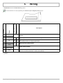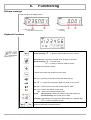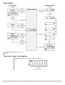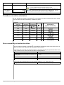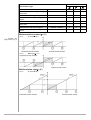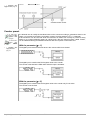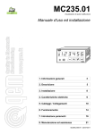
1
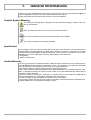
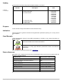
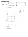
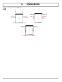
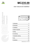
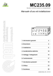
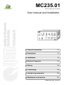
MC235.01
Quotas multifunction visualizator
User manual and installation
1. General information
3
2. Description
5
3. Installation
8
4. Electric Properties
9
5. Wiring
10
6. Functioning
14
7. Introducing parameters
16
8. Maintenance and service
21
MUIMC235010EN - 25/07/2011
1. General Informations
1.1
1.2
1.3
1.4
1.5
1.6
1.7
1.8
Graphic Symbol Meaning...................................................................................3
Specificated........................................................................................................3
Limited Warranty.................................................................................................3
Validity.................................................................................................................4
Purpose..............................................................................................................4
Indication............................................................................................................4
User Manuals......................................................................................................4
Norm references.................................................................................................4
2. Description
2.1
2.2
2.3
2.4
3
5
Product code.......................................................................................................5
Accessories........................................................................................................6
Technical characteristics.....................................................................................6
Mechanical dimensions......................................................................................7
3. Installation
8
4. Electric properties
9
4.1
4.2
4.3
Power supply......................................................................................................9
I1 / I2: Digitalis inputs........................................................................................9
PH A /PH B: Bidirectional endoder phases........................................................9
5. Wiring
5.1
Wiring examples.................................................................................................11
6. Functioning
6.1
6.2
6.3
6.4
16
Programming (Set-up)........................................................................................16
Transducer resolution calculation.......................................................................17
Errors caused by not ended risolution................................................................17
Counter reset (C = 1*) .......................................................................................18
Relative/absolut counter(C = 2*) .......................................................................18
Angular visualization...........................................................................................18
Counter preset....................................................................................................20
8. Maintenance and service
8.1
14
Release message...............................................................................................14
Keyboard functions.............................................................................................14
Using graphic......................................................................................................15
“Data out of range” visualizzation ......................................................................15
7. Parameters introduction
7.1
7.2
7.3
7.4
7.5
7.6
7.7
10
Indication for service fax compiling....................................................................21
21
1.
General Informations
Thanks for buying this QEM instruments. We'll be glad to receive at our e-mail address [email protected]
all your suggestions referred to this instruments end to the user manual.
Finally we suggest you to preserve this manual for future consultations.
Graphic Symbol Meaning
Not reading the message will be dangerous for the instruments integrity and/or for the success of the operation.
Note: Important information for the correct use of the instruments.
For more informations see the user manual indicated in the message.
For more informations see the pages indicated.
Specificated
The copyright of this user manual is reserved. No one part of this document can be reproduced or
copyed without the QEM appointment. QEM doesn't present insurances or warranties on contents
and declines all responsabilities on identity warranties. In this document, informations can be modified without any notice. QEM desn't have any responsability on this document.
Trade Marks:
- QEM® is a trade mark.
Limited Warranty
For two (2) years from the original acquisition, QEM will repair or replace for free controls and devi ces that QEM thinks be imperfect in materials or quality. This warranty is not valid if the object has
been tampered by not autorized persons or used in an inappropriate way.
This warranty replaces all other warranties either expressed or implicit.
QEM desn't hold personally responsible for all charges (installation or uninstalling included), drawback, or damage caused by our products, made or sold. In any case, QEM total duty, always will not
exceed the control total price.
Claims for refunds of selling price, reparations, or replacements must be referred to QEM with all
pertinent data (damage, purchase date, developed work and problem).
It is not provided any duty for batteries and fusible cut-out consumption.
The product must be returned only with a written notification, included the Number of Restitution Au torization QEM and must be paid all forwarding charges.
Graphic Symbol Meaning
MUIMC235010EN - 15/12/2010
3
Validity
The present document is fully valid excepted mistakes or omissions.
Instrument
Release
M: Manual;
S: Instruments.
0
Description
Date
M New manual.
M Data corrections.
M Content review.
14/07/2005
29/07/2005
02/08/2005
30/08/2005
06/09/2005
14/09/2005
14/11/2005
28/02/2007
17/04/2007
03/10/2007
15/12/2010
25/07/2011
M Insert new code
M Insert CX9 model
M Input's note
Purpose
This manual could give informations for the instrument using.
Indication
We raccomand to guard all instruments Programmation parameters (Set-up) for an easy service
ore reaplace.
User Manuals
The documentation referred to the QEM strumentation in divided in many issues that allows an
easy utilization.
MUI: User and installation manual
Instrument hardware and software informations.
MIMAT: Maintenance, service and installation manual.
Informations on: wiring, right calibration, parameters insertion and breakdown
individuation.
It is possible to download manuals from www.qem.it
Norm references
European norm includes some rules and raccomandations about control security systems with elements of operator interface.
Protection rate
IP20 (Conforme a EN 60-5-29)
Frontal protection rate for container (optional)
IP54
IP65 frontal protection rate with packing for
container(optional)
IP65
Vibration resistance
Conforme a IEC 68-2-6
Bump resistance
Conforme a IEC 68-2-27
Jamming immunity
Conforme a EN 50082-2
Emission level
Conforme a EN 50081-2
Container
DIN43700
Graphic Symbol Meaning
MUIMC235010EN - 15/12/2010
4
2.
Description
For more informations contact QEM sales office.
MC235.01 is an instrument made for viualize an incremental bidirectional encoder count.
This instruments replace: EC235.01, EC235.01A, EC235M01.
General Characteristics
– Bidirectional count;
– Resolution multiplier;
– Loading preset quota;
– Programmable input;
– Not volatile storage;
– Unscratchable keyboard with tactile feelingcon;
– Incorporated encoder alimentation;
– Absolut/incremental counter visualization;
– Extractable polarized junction-box.
New functions
– Angular visualization in sexagesimal degrees;
– Display not significative zero turning off;
– Programmable philter antiglitch on inputs.
Options
- Personalized panel;
- Dedicated power supply voltage;
- Superior encoder counter frequencies;
- Specialization on customer specifications..
Product code
Model
MC235
Characteristics
.
01
/
T001
Firmware
version
/
CX2
/
U04
/
Instrument
supply
Mother board
CX2 (standard)
Keyboard code
T001 = standard
keyboard.
24Vac
Expansion board
(omitted if not
CX_ : Basic Card
PHA / PHB:
Encoder
phases
I1 / I2:
Digital
inputs
Vout ext
Frequency
Encoder type
Voltage level
phases
Frequency
Polarization
CX1 CX2 CX3
15 KHz
PP
of
encoder
Inputs voltage level
Delivered power supply
Graphic Symbol Meaning
CX4
CX5 CX6
200 KHz
NPN
CX8
LD
12 / 24 V
PNP
CX7
CX9 CXA CXB
15KHz
50 KHz
PP
PP
2 / 3,5 V
10 KHz
PNP NPN
PNP
100 KHz
NPN
10,5 / 26,5 V
12 V
MUIMC235010EN - 15/12/2010
5V
12 / 24 V
10KHz
10 KHz
PNP NPN
5V
5V
10,5 / 26,5 V
12 V
5
Accessories
Description
Codice d'ordinazione
Container frontal protection (IP54)
23040001
Packing frontal protection for container (IP65)
23040044
Misured in mm.
Technical characteristics
weight (max. hardware composition)
450
Container material
Plastic noryl UL 94 V-O
Display
1
6
display h = 8
display h = 14
Buttons
4
mechanical buttons with tactile feeling
Led
5
Working temperature
0 / 50
°C
Relative humidity
90%
senza condensa
Altitude
0 / 2000
m s.l.m.
Atmosphere
Not corrosive gasses
Transport and stocking temperature
-25 / +70 °C
Graphic Symbol Meaning
MUIMC235010EN - 15/12/2010
gR
6
Mechanical dimensions
Misured in mm.
Mechanical installation
pag. 8
Fig. 1 Back view
Fig. 2 Perforation area
Graphic Symbol Meaning
MUIMC235010EN - 15/12/2010
7
3.
Installation
For a correct installation read MIMAT manual
a) Insert the instrument in the hole;
b) Apply hooks;
c) To fix the instruments screw down.
Graphic Symbol Meaning
MUIMC235010EN - 15/12/2010
8
4.
Electric properties
Power supply
* = Variable data. See
the model Basic Card
CX_ (pag. 5)
Available power supply
Vac
Vdc
24 / 27 / 110 / 230 Vac
24 Vdc
Range val
-15 / +10%
Frequency
50 / 60 Hz
18 / 30 V
dc
Assorbimento max.
8 VA
Volt ext.*
12 Vdc - 100mA
I1 / I2: Digitalis inputs
* = Variable data. See
the model Basic Card
CX_ (pag. 5)
Polarization *
CX 1
CX 2 (standard)
PNP
NPN
Frequency *
10 Khz
Optoinsulation
N.B.: For the other inputs' features, please
contact QEM's sales
office.
1500 V rms
Nominal operating voltage
12 / 24 Vdc
Logic state 0 Voltage
<3 V
Logic state 1 Voltage
>8 V
Input resistance
1,5
KΩ
Internal voltage drop (see Fig.3)
1,2
V
Lowest acquisition time I1
Activation C
50 ms
Activation I
10
Lowest acquisition I2
µsec.
50 ms
C: continuos
I: impulsive
Fig. 3 Internal voltage drop
PH A /PH B: Bidirectional endoder phases
Encoder 12 V
* = Variable data. See
the model Basic Card
CX_ (pag. 5)
Polarization *
Frequency *
Optoinsulation
N.B.: For the other inputs' features, please
contact QEM's sales
office.
Encoder 24 V
CX 1
CX 2 (standard)
PNP
NPN / Push - Pull
20 Khz
1500 Vrms
Logic state 0 Voltage
<3
Volt
Logic state 1 Voltage
>8
Volt
Input resistance
1,5
KΩ
Internal voltage drop
1,2 Volt
Graphic Symbol Meaning
MUIMC235010EN - 15/12/2010
9
5.
Wiring
* = Variable data. See the model Basic Card CX_ (pag. 5)
For more information on l1 input programming, see Function l1 input in Program (set-up) at pag 16
Way of activation
Logic activation state
Name
Terminal
Fig. 4 Back connector
Description
1
12 V *
2
0V
3
I1 / PH Z
On
4
I2
On
C
Digital input I2.
Zero setting counter, or charging permission.
5
PH A
6
PH B
On
I
Bidirectional encoder phases.
7
Vac / - Vdc
8
Vac / + Vdc
9
GND
-
Volt ext.
C / I Digital input I1 / Phasease Zero encoder. Programmable.
-
Power supply voltage.
-
Ground connection.
Connect a conductor with 2mm2 section to the PE bar.
C: continuos
I: impulsive
Graphic Symbol Meaning
MUIMC235010EN - 15/12/2010
10
Wiring examples
The wiring examples change according to Basic Card CX characteristics installed in the instrument. (pag. 5)
For other wiring example read MIMAT manual.
Possible only with Basic Card CX2.
Basic card CX2 (Standard)
Fig. 5 Digital input polarization NPN.
Bidirectional encoder phases connection rNPN / Push Pull.
Fig. 6 Digital input polarization NPN.
Bidirectional encoder phases connection NPN / Push Pull with I1 Impulsive.
Fig. 7 Digital input polarization NPN.
Bidirectional encoder phases connection rNPN / Push Pull feeded externally
Fig. 8 Bidirectional encoder phases connection rNPN / Push Pull with 2 proximity like encoder.
Graphic Symbol Meaning
MUIMC235010EN - 15/12/2010
11
Fig. 9 Digital inputs NPN connected to a PLC feeded by a MC235.01.
Fig. 10 Digital inputs NPN connected and feeded (Vdc) by a PLCI
Basic Card CX1
Fig. 11 Digital input polarization PNP.
Bidirectional encoder phases connection PNP
Fig. 12 Digital inputs PNP connected to a PLC and feeded by a MC235.01.
Fig. 13 Digital inputs PNP connected and feeded (Vdc) by a PLC
Graphic Symbol Meaning
MUIMC235010EN - 15/12/2010
12
For a correct installation see MIMAT manual.
Power supply connections
5.1.1.1
Notes
Fig. 14 Use a transformer 50VA
min. sec. 24 Volt
Fig. 17 Don't use auto transformer
Fig. 15 Don't connect power supply
voltage to the groud
Fig. 16 Don't connect the transformer central terminal to the ground
Fig. 18 Don't use tranformer headed by an autotransformer
Fig. 19 Don't set coils, electro-valve etc. in parallel
Graphic Symbol Meaning
MUIMC235010EN - 15/12/2010
13
6.
Functioning
Release message
At the turning on the display shows:
1°: a) Instrument family;
b) Instrument firmware version.
2°: c) Release;
b) Granting.
Keyboard functions
Fig. 20 keyboard
Some Il funzbuttons functioning depends
by the Programmation
(Set-up) pag. 16.
Data insertions: It confirms the data introduction.
Normal working: If E = 1, allows a value introduction in the counter.
Enter
Clear
Data insertions: Cancel the inserted value, giving the past value.
Normal working: If C = 1 counter reset;
If C = 2, allows / not allows relative counter.
It increases the selected number.
It selects the number with a shift from left to right.
Led. ON = gives the parameters introduction state (set-up).
Led. If E = 1, informs the introduction state of a value on the counter.
Led. ON = informs the access to the storage register “PRS”.
Led. ON = informs the relative counter state.
OFF = informs the absolute counter state.
a) Led.
Data insertion: informs the insertion sign state (direction).
Normal working: informs the input l1 state.
b) Display (first display from left) gives a differentiation of visualized data.
If A = 1 informs negative counter.
+
Graphic Symbol Meaning
Access to password protected functions
MUIMC235010EN - 15/12/2010
14
Using graphic
*
= Programmation (Set-up) parameter pag. 16
Led = Off.
Led = On.
“Data out of range” visualizzation
If introduced data are out of range, the display visualizes:
a) Data out of range
Graphic Symbol Meaning
MUIMC235010EN - 15/12/2010
15
7.
Parameters introduction
Programming (Set-up)
Parameters define the instrument functioning way, their access is reserved to an installator with a password.
Description
Keyboard
Visualizzation
For entering in the Programming (Set-up).
+
x 3 sec.
Introduce the access code “235” and confirm with
enter.
Function
CLEAR button
functions
ENTER button
functions
Activation counter
sign
Decimal cypher
Max. 3
Counter exit code
Transducer risolution
H
Display
C
E
A
H... 0
235
Description
0
0
1
P
0
U
0
L100000
0 = BLOCKING FUNCTION;
1 = COUNTING RESET;
2 = ACTIVATE / DEACTIVATE RELATIVE COUNTER.
0 = BLOCKING FUNCTION;
1 = COUNTER INTRODUCTION BY KEYBOARD.
see Using graphic pag. 15
0 = WITHOUT SIGN COUNTER(one under zero = 999999);
1 = COUNTER WITH SIGN (one under zero = -1).
If parameter d = 0, 1 or 2
SPECIFIES THE NUMBER OF DECIMAN CYPHERS.
If parameter d = 3 or 4
Specifies:
0 = DEGREES VISUALIZATION;
1 = DEGREES VISUALIZATION.
Parameter value = 0.
ENCODER REVOLUTION IMPULSE MOLTIPLIER to visualize
lenght in the correct unit of measure.
Range: 0.00200 / 4.00000
the
For other information seeMIMAT.
Visualization
ways
d
0
0 = NORMAL VISUALIZATION.
1 = Visualization with HDR system type 1.
2 = Visualization with HDR system type 2.
3 = MONOREVOLUTION sexagesimal vsualization.
4 = MULTIREVOLUTION sexagesimal visualization.
For other informations see MIMAT.
Input function I1
F
0
0 = NO ONE FUNCTION.
1 = CONTINOUS CHARGING PRS storage register on the counter.
2 = IMPULSIVE CHARGING PRS storage register on the counter
Counter preset pag. 20
3 = ADDS the prs storage register content to the counter.
4 = SUBTRACTS the prs storage register content il contenuto del registro di memoria prs to the counter.
5 = SICURITY protecting programmable functions; possible programmation only with l1 input = ON (connectable to a key interruptor).
Graphic Symbol Meaning
MUIMC235010EN - 15/12/2010
16
Function
Display
Description
6 = VISUALITATION BLOCK.
In 1,3,4,5,6, functions the l2 input reset the contonous conter.
Selecting functions 0,1,3,4,5,6, l1 input has acquisition time 50 milliseconds.
PRS storage
register
Led = ON. Introducing the value referred to the PRS storage register
(value charged on the counter with the l1 input, if applied).
0
At the end of the programming, the instrument returns at the normal visualization.
Transducer resolution calculation
L
In the “transducer resolution” parameter ( ) is the number of measure units that we want to visualize in th impulse number generated by a transducer phase.
Exemple:
Space in unit of
measure
Transducer
impulses
Transducer
resolution
S
I
L=S/I
500
2000
0,25000
0, 1, 2
0
500
2000
0,25000
0, 1, 2
1
7423
4096
1,81226
0, 1, 2
1
5000
2000
2,50000
0, 1, 2
1
360
9000
0,04000
3, 4
0
21600 (360x60)
9000
2,40000
3, 4
1
d P
Visualization
(impulse conversion)
500
50 0
742 3
500 0
360
360 00
Errors caused by not ended risolution
L
In the “transducer risolition” parameter ( ) is possible to specifing the value of the factor for the inpulse conversion with a precision up to the fifth decimal number.
If the factor has more than five decimal number is necessary inserting an approximed value. In this
case we have an error. Here we can see when it cause problems.
If the space in a tenth part of mm is
S = 7423
And it correspond to a transducer impulse num- I = 4096
ber equal to
The technical resolution is
L = 1.812255859...
Approximated to
L = 1.81226
In this way every 4096 impulses you have an error equal to 5 x 10⁻⁶ tenth part of mm.
You get after
4096 / (5 x 10⁻⁶ ) = 8192 x 108 impulses
Graphic Symbol Meaning
MUIMC235010EN - 15/12/2010
17
The measure visualization is uncorrect for the tenth part of mm. Now the user has to decide if this
imprecision is tollerable for his application.
The possible cases are:
The impulse number to have an error of a tenth part of mm is hight and in the application can'7
be reached without before reset the counter, so there aren't problems. The impulse number can
be reached, but the error is no relevant for the application. The highest impulse number reached during the application without reset the counter, is much bigger than the calculated value.
So the error results bigger than the tenth part of a mm that is innaceptable. It this case is suggested to modify the mechanic or the transducer impulse number to reach an ended value up
to the fifth decimal.
Counter reset (C = 1*)
* = Program (Set-up)parameter pag. 16
Relative/absolut counter(C = 2*)
* = Program (Set-up)parameter pag. 16
Angular visualization
Can be employe this unit of measure:
Rad
Hundredth degree
Sexagesimal degree
Revolution angle
2 π rad
360.00°
360°00’00”
According to the application requirement the visualization could be monorevolution or multi revolution; in the below tabulation are persent the impostation to obtain the different visualizations:
Graphic Symbol Meaning
MUIMC235010EN - 15/12/2010
18
Parameter impostation *
Visualizzation type
Monorevolution without sign in degrees
Monorevolution without sign in degrees
and primes
Monorevolution with sign in degrees
Monorevolution with sign in degrees and
primes
Multirevolution without sign in degrees
Multirevolution without sign in degrees
and primes
Multirevolution with sign in degrees
Multirevolution with sign in degrees and
primes
d
P
A
3
3
0
1
1
1
0° / 999999°
0° 00' / 9999° 99'
4
4
0
1
0
0
- 999999° / 999999°
- 9999° 99' / 9999° 99'
4
4
0
1
1
1
0° / 360°
0° 00' / 360° 00'
-360° / 360°
- 360° 00' / 360° 00'
3
3
0
1
0
0
Monorevolution counter (d = 3*)
7.1.1.1
No segn (A = 0*)
7.1.1.2
With segn (A = 1*)
* = Program (Set-up)parameter pag. 16
Multirevolution sign(d = 4*)
7.1.1.3
Graphic Symbol Meaning
No segn (A = 0*)
MUIMC235010EN - 15/12/2010
19
* = Program (Set-up)parameter pag. 16
7.1.1.4
With segn (A = 1*)
Counter preset
For other information see Navigation card
at pag15
For more information
read
the
MIMAT
It is allowed user to modify the visualized value on the counter according to misurations done in the
range. It is necesary to permit the “Introdution counter” function setting the “ E=1”* parameter.
If the transducer con be removed while the instrument is feeded, it's necesay to provide at every
switch on to counter rephasing respect to a phisic point i the axis; these functions, called “Preset”,
con be obtained utilizing incremental transducer with zero impulse or with stroke end.
manual.
With the parameter (F = 1*)
•
The digital input l2 resets and blocks at zero the counter while it is activated.
= Program (Set-up)parameter
pag. 16
The digital input l1 transfers the PRS register value to the counter.
The counter is blocked at the PRS value while the input is activated.
With the parameter (F = 2*)
The digital input l1 transfers the PRS register value to the counter only if l2 is active.
The counter is not blocked.
Graphic Symbol Meaning
MUIMC235010EN - 15/12/2010
20
8.
Assistance
Request for assistance
To provide you a faster service, at a minimum cost, we do need your help.
a)
a) Follow all the information in the manual MIMAT (www.qem.it)
b)
b) If the problem persists, fill the Module for
technical service attached to this manual and
send it to QEM.
c)
c) Our technicians will get the fundamentals
elements to understand your problem.
Shipment
We recommend to pack the instrument with materials that can damp eventual falls.
a)
a) Use the original package: it has to protect
the instrument during the transportation.
b)
b) Attach:
- An anomaly description;
- Part of the electrical sketch where the instrument is inserted
- Programming of the instrument (set up, working quotes, parameters..).
- Request of a repairing estimate; if not requested the cost will be calculated at the end.
c)
c) An exhaustive description of the problem
allows to find and solve your problem. An
accurate package avoids further drawbacks.
QEM informs the courteous costumer that the shipped instruments unfairly packed won't be repaired, except for the ca ses where the costumer assumes completely the reparation cost.
Motivations
The QEM established like that because a too strong line may cause damages that could reveal in a temporal space of
some months, causing doubts and shadows on the reparation done.
Graphic Symbol Meaning
MUIMC235010EN - 15/12/2010
21
Modulo fax per Assistenza Tecnica
Module for Technical Service
Ditta / Firm :...............................................................
Rif.:.............................................................................
Indirizzo / Address:...............................................................................................................................................
...........................................................................................................................................................................
................
Tel..............................................................................
Fax..............................................................................
E – mail..............................................................................................................................................................
Codice strumento / Instrument Code :................................................................................................................
Alimentazione strumento / Power Supply: .............................................................................................................
Tipo di macchina / Machine type:
...........................................................................................................................................................................
...........................................................................................................................................................................
...........................................................................................................................................................................
...........................................................................................................................................................................
...........................................................................................................................................................................
...........................................................................................................................................................................
Descrizione ciclo macchina / Cycle machine description:
...........................................................................................................................................................................
...........................................................................................................................................................................
...........................................................................................................................................................................
...........................................................................................................................................................................
...........................................................................................................................................................................
...........................................................................................................................................................................
Parametri / Parameters:
...........................................................................................................................................................................
...........................................................................................................................................................................
...........................................................................................................................................................................
...........................................................................................................................................................................
...........................................................................................................................................................................
...........................................................................................................................................................................
...........................................................................................................................................................................
...........................................................................................................................................................................
...........................................................................................................................................................................
...........................................................................................................................................................................
...........................................................................................................................................................................
Descrizione anomalia / Anomaly Description:
...........................................................................................................................................................................
...........................................................................................................................................................................
...........................................................................................................................................................................
...........................................................................................................................................................................
...........................................................................................................................................................................
...........................................................................................................................................................................
Frequenza anomalia / Anomaly frequency :
Graphic Symbol Meaning
Continuo / Continous
Saltuario / Irregular
Dopo un certo tempo / After a few time
All'accensione / At the switching on
Allo spegnimento / At the switching off
Altro / Other: ...........................................................
....................................................................................
....................................................................................
MUIMC235010EN - 15/12/2010
22
Graphic Symbol Meaning
MUIMC235010EN - 15/12/2010
23
QEM S.r.l.
S.S. 11 Signolo n. 36,
36054 Montebello Vic. No
Vicenza – ITALY
Tel. +39 0444 440061
Fax + 39 0444 440229
http:\\www.qem.it
e-mail: [email protected]
La marcatura CE dello strumento non solleva l' Installatore dal recepimento e adempimento
degli obblighi normativi di riferimento al proprio prodotto.
Graphic Symbol Meaning
MUIMC235010EN - 15/12/2010
24