1
MagnaTran 7.1 User’s Manual
MN-003-1600-00
Subsystems
Electrical System
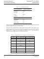
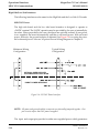
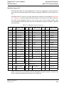
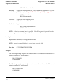
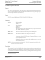
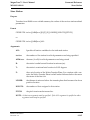
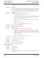
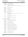
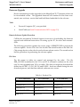
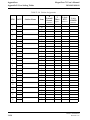
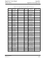
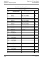
the face plate. This connector provides 20 optically isolated high side inputs
and 20 optically isolated high side outputs designed to operate at +24VDC
nominal. The 24 VDC operation is provided through the system.
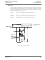
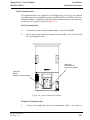
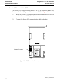
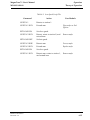
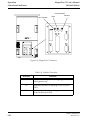
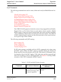
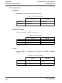
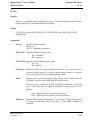
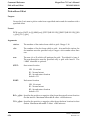
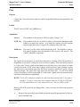
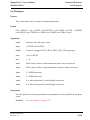
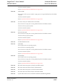
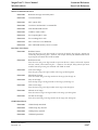
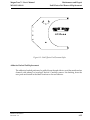
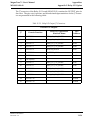
The high side board has the following connectors:
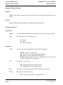
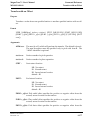
POWER: Main Power Connector, on the face plate but not actually on the I/O
board
CDM: Dedicated Control Display Module (CDM) port
SIO1: Main Serial Communications port, RS-232 or selectable RS-422
SIO2: Secondary RS-232 port
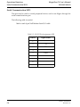
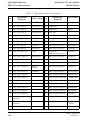
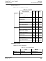
MISC IO: Discrete I/O Port
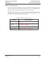
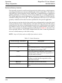
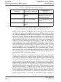
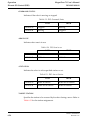
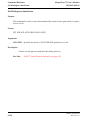
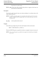
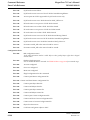
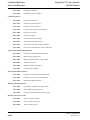
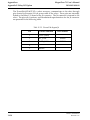
The high side board has the following indicators:
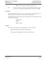
24V: Power on indicator
TX: SIO1 transmit, green indicator
RX: SIO1 receive, green indicator
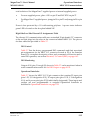
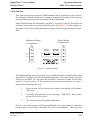
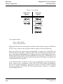
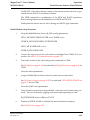
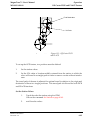
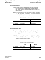
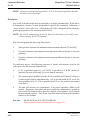
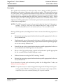
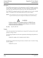
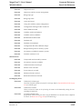
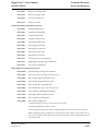
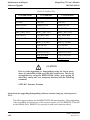
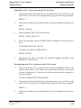
The high side interface is designed to operate at +24VDC. This power may be supplied through the connector by the user. When supplied externally, full optical isolation is achieved. Optionally, the user may use the I/O interface without supplying
power. The I/O board will automatically switch to internal power. Isolation will then
be defeated.
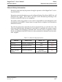
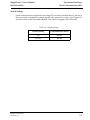
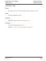
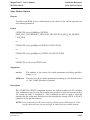
Nominal current requirements for each input is 2mA each. Output current is nominal
200mA per pin.
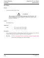
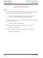
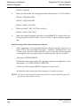
The I/O board is also offered as a low side switching interface. See Appendix F: Relay
I/O Option on page 11-24 for a description of the low side board.
Brooks Automation
Revision 2.2
4-13