1
RS-232/485 Ethernet converter
&
Ethernet I/O Controller
RS232/485 <-> ETHERNET Converter
The complete shipment contains
•
•
•
Closed converter box with a unique preset MAC address.
RS232 interconnection cable (serial port extension cord, Cannon 9 - 1:1)
Datasheet.
We can supply upon request:
• Brackets for wall mounting.
• RS232/RS485 conversion module (no galvanic insulation)
Basic communication types
TCP server (Passive mode)
After powering up, the converter listens on the given port and awaits client connection. When the
client connects, data from the Ethernet are sent to the serial line and vice versa. If the client is not
connected and data are coming from the serial line, they are stored in a buffer (size is configurable)
and transmitted immediately after establishing a connection, unless clearing of the buffer upon
establishing a connection has been requested in the SETUP.
TCP client (Active mode)
The converter behaves similarly to the previous case. However, when data arrive from the serial line,
it tries to actively establish the connection to the specified remote IP address as a client and transmit
the data. If it does not succeed, data are kept in the buffer and transferred as soon as a connection is
established, regardless of the converter connection mode (client or server). In this mode, two
converters communicating with each other can "tunnel" the serial line through the Ethernet. And,
when using the Charon modules or the I/O Controller, the Ethernet can be used to extend the parallel
inputs and outputs as well.
UDP
Data from the Ethernet are expected on a given port. Data coming from the serial line form a packet
according to the specified triggers and are sent to a specified IP address. During UDP transfer,
acknowledgements from the remote side are not verified; the application itself should support
recovery from a data loss. An advantage is a shorter response time, useful especially for RS485
lines.
NVT (Network Virtual Terminal)
When using TCP/IP communication, the converter function can be enhanced via NVT according to
RFC2217 using a control data stream that can, for example, change the baud rate of the remote
serial port, control inputs and outputs, or clear the buffer. These control commands are mixed into the
data stream and prefixed with "FF" ("FF"s in the regular data stream are doubled). Detailed
description of NVT is available in the "Programming Ethernet Applications" guide at our website
that also describes the supplied communication subroutines.
February 2003
HW server
page 2 / 18
Europe – Czech republic - Prague (Phone +420 222 511 918)
www.HWgroup.cz
RS232/485 <-> ETHERNET Converter
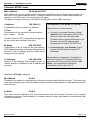
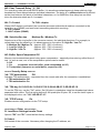
RS232/485 - ETHERNET Converter
The asynchronous serial line conversion to the ethernet include support of
RS485 protocols. Features : TCP/IP , UDP/IP., NVT, TEA and many more..
The I/O Controller contains all functions of the converter and adds support
of 8 + 8 binary inputs + outputs with using the NVT– see the last chapter…
Converter features
•
•
•
•
•
•
•
•
•
•
•
•
Serial RS232 port accessible over an Ethernet network.
Configurable communication speed 300..115200 Bd, handshake (CTS/RTS, Xon/Xoff, none)
RJ 45 interface - 10BASE-T and RS-232.
Parameters configured locally over RS232 or over the Ethernet using a Windows application.
Support for TCP/IP data transfer - TELNET-like client + optional NVT support (Network
Virtual Terminal)
Option to activate UDP transfer with RS485 support.
Triggers for packet start and packet end.
Support for passive or active mode (the converter can establish a connection with the remote
side upon serial line activity)
Two devices can extend a serial port over the Ethernet.
Security measures consist of a fixed specification of the remote IP address range and optional
connection authorization using the 128-bit TEA encryption algorithm.
Support for interfacing with special software, or a Windows configuration application.
It is possible to add x51 assembly code for protocol conversion between the Ethernet and
the serial line. This way the converter can for example recognize your proprietary protocols
and so on.
Converter Applications
•
•
•
•
Instrumentation control and monitoring over the Ethernet.
Connection of any device controlled over RS232 to the Internet through Ethernet.
Securely authorized access to a device over the Internet from anywhere.
Support for UDP communication - fast and advantageous for Ethernet LANs.
Basic HW parameters
Electrical parameters
Network parameters
Supported protocols
TCP/IP + NVT, UDP/IP
Dimensions
DC 8-20V / 0 2A - Polarity:
38 x 105 x 135 (H x W x D )
RS232 - transfer rate
300 – 115.200 Bd
Temp. ranges
Temperature : 5 – 50 °C
RS232 – data stream
RTS/CTS, Xon/Xoff, none
Ethernet
RJ45 – 10BaseT – IEEE 802.3
RS232 - data
8 or 7 data bits
Serial port
1x DB9F (RxD,TxD,RTS,CTS,GND)
RS232 – parity
None/Odd/Even/Mark/Space
RS485
With internal RS485 module only
TCP connection close
Data/ACK/NOP timeout 50s
Power supply
February 2003
HW server
page 3 / 18
Europe – Czech republic - Prague (Phone +420 222 511 918)
www.HWgroup.cz
RS232/485 <-> ETHERNET Converter
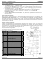
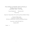
Connector description
PC RS232 Port
Cannon 9 - Male
Pin
Signal
1 <CD
2 <RxD
3 ->
TxD
4 ->
DTR
5 -GND
6 <DSR
7 ->
RTS
8 <CTS
9 <RI
RS232 Converter Port
Cannon 9 - Female
Pin
Signal
1 <->
2 ->
TxD
3 <RxD
4
Setup ON
5 -GND
6
„B“ RS485
7 <CTS
8 ->
RTS
9 <->
„A“ RS485
Power supply:
DC 8..20V / max. 0.3 A
Ethernet :
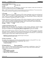
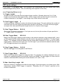
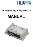
RS485 converter module
The module for physical RS485 conversion is not supplied. However, it can
be ordered as a separate accessory for no additional charge. The RS485 line
is wired according to the description of the Cannon 9 connector. When
installing the module, please remove the top two jumpers and insert the
module.
For configuration, you will probably need to use the original RS232. Do not
forget to insert the two jumpers after removing the module. Looking at the
converter with the Cannon 9 and RJ45 connectors on the right side, the top two jumpers next to the
Cannon 9 connector need to be in place. Two empty jumper positions should remain below them.
Here is a detailed diagram of the connector wiring.
Converter connection configurations
Converter
<-TCP/IP->
PC
The PC can open a network connection, e.g. with the TeraTerm program, to the converter IP address
and port 23. For the opposite direction, a server program needs to be installed on the PC. This mode
is the most common one for monitoring and remote control of any device over the serial port.
Converter
<-UDP/IP->
PC
Special software is needed for connecting to the converter. UDP is intended for transferring data on a
local segment of an internal network only. We do not recommend UDP for communication over
longer distances.
Converter
<-TCP/IP->
Konvertor
Two devices bridge the serial ports over the Ethernet network - creating a "virtual wire". Converters
can authorize themselves upon establishing the connection, remote IP addresses can be restricted.
As a result, serial ports of two devices can be connected together via the world-wide network. The
serial ports can communicate with different speeds; this can sometimes decrease latency.
Converter <-UDP/IP-> Konvertor
Special software is needed for connecting to the converter. UDP is intended for transferring data on a
local segment of an internal network only. We do not recommend UDP for communication over
longer distances.
February 2003
HW server
page 4 / 18
Europe – Czech republic - Prague (Phone +420 222 511 918)
www.HWgroup.cz
RS232/485 <-> ETHERNET Converter
Installation
Mechanical installation
Converter is supplied in a metal box with four self-tapping screws in the sides. The screws are 80 mm
apart, their diameter is 3 mm. The box can be attached with these screws into a custom "L" profile
1.2 mm thick. We supply the sidewise "L" profiles as optional accessories. Drawings of the box and
the profiles are available upon request.
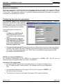
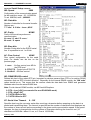
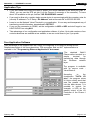
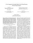
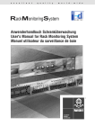
Configuring the converter parameters
The converter needs to be configured before it can be used in routine operation.
parameters (IP address, mask, gateway,
serial port speed, etc.) can be configured
by the software shown in the figure. It is
available for download at our website.
Converter
Three configuration methods are
available:
•
•
•
Locally over a RS232 serial
line. All parameters can be
configured using a textual setup
menu.
Over the network, using an
UDP application for Windows.
Basic network parameters are
configurable.Limited to a local
Ethernet segment only.
Over the network using TCP (everything can be configured and the device can be anywhere;
however, the netmask, GW and IP address must be pre-configured and cannot be changed in
this mode). Remote configuration over TCP/IP has to be enabled through a special option
accessible in the RS232 SETUP.
SETUP over the serial RS232 line
For converter configuration, set the RS232 line parameters to 9600Bd, 8N1. The PC can be
connected using the supplied cable with Canon 9 connectors.
Activation of the setup mode:
•
Drive pin 4 (DTR) low when the converter powers up. Jumper JP3 needs to be in
the 1-2 ("PC") position - factory default. This method is used by the configuration
SW.
•
Automatically at power up, if the jumper JP3 is in the 2-3 position ("SETUP"). (to
the left from the connectors).
•
The setup menu cannot be activated if the jumper JP3 is removed entirely.
February 2003
HW server
page 5 / 18
Europe – Czech republic - Prague (Phone +420 222 511 918)
www.HWgroup.cz
RS232/485 <-> ETHERNET Converter
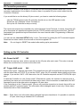
The converter can be configured using any terminal in line mode, you don't need our software.
However, in that case, you need to manipulate with the JP3 jumper, or need a terminal that can
define the value of DTR - for example, TeraTerm can't do it.
The configuration itself is performed by communicating with the converter over the serial line. After
powering up, the converter tests the JP3 jumper. If present, it sends the following screen over the serial
port. (Port settings: 9600 Bd 8N1)
If the converter does not respond, verify the serial port settings. If no success, verify the serial cable
wiring. Then, verify the JP3 setting on the converter board. Network activity (receiving and
transmitting) is indicated by the LEDs ETx and ERx on the PCB turning off. The converter reacts to
ICMP Echo requests ("ping") for the given IP address. Response time is 4 ms. To set the IP address
for testing "PING" replies, our program in UDP mode can be used.
The configuration itself is performed by typing the letter(s) identifying the option and its value. (for
examle „I192.168.6.8“ to set the device IP address).
Help for an option is printed by sending its letter, question mark and <Enter> – „I? <Enter>“.
A figure detailing this configuration process is shown on the page with the list of configuration options.
Over the network using UDP
The configuration is performed using our program; see the figure on the previous page. In this mode,
the converter can be detected and configured on a local network segment only. No routers, firewalls,
or other devices filtering UDP broadcasts can stand in the way.
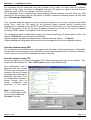
Over the network using TCP
Using our program or any telnet that supports TEA. See the figure on this page for an example. This
setup can be disabled by the "%S: TCP/IP setup" option in the RS232 setup.
This configuration mode is
protected with the chosen
TEA key that is required for
access to the device (unless
the password requirement is
disabled in the setup). Thus,
the configuration process is
secure enough even for
remote configuring from
anywhere in the world.
Note: Configuration over
TCP is not possible for HW
version 4.5 and the "I/O
Controller" version.
February 2003
HW server
page 6 / 18
Europe – Czech republic - Prague (Phone +420 222 511 918)
www.HWgroup.cz
RS232/485 <-> ETHERNET Converter
Application tips and recommendations
Security
To increase security in TCP mode, both sides can authorize themselves via the symmetric TEA 128
cipher whenever a connection is established. The password set on both sides will not travel over the
network. This option is available only for TCP/IP connections. UDP mode is intended for local networks
only. Detailed TEA description is available in the "Programming Ethernet Applications" guide at our
website.
Increasing connection timeout
Since the converter supports only one concurrent connection, a timeout needs to be set. By default, a
connection is terminated 50 seconds after the last data transfer. However, it is possible to enable "K:
Keep connection" to send a NOP into the open NVT connection once about every 10s. Starting with
version 2.4, a new function will allow a connection to remain open after timing out until someone else
wants to establish another connection. In that case, if no data are transmitted for about 50s and
someone else tries to access the converter, the converter closes the inactive connection and attends
to the new connection.
Access to the NVT port
Starting with version 2.4, a separate port with enabled processing of NVT commands is implemented
on the same IP address. The original port can have the NVT commands turned off. This can be used
for example to create a transparent "raw" conversion from the IP address to RS232 and at the same
time control inputs and outputs via NVT on another port, or use 9-bit RS232 communication.
Packet triggers in the UDP mode
The converter in UDP mode supports RS485 protocols. By configuring the protocol parameters, response
time over the Ethernet can be reduced from about 20-100 ms in TCP/IP mode to 10-20 ms.
The converter can recognize the end of a RS485 packet and send the data to the other side without
waiting for a timeout to expire. The following conditions trigger the end of collecting data from RS485 and
transmission over the Ethernet in one packet. When the triggers overlap, the packet is sent if any one of
them is activated. Start and end of a packet is triggered by a sequence of 1 to 4 bytes with a configurable
mask.
February 2003
HW server
page 7 / 18
Europe – Czech republic - Prague (Phone +420 222 511 918)
www.HWgroup.cz
RS232/485 <-> ETHERNET Converter
Converter SETUP mode
MAC Address
00:0A:59:00:95:6C
MAC address is a unique network device address in the Ethernet and is always factory-preset. You
can find it on the label inside the device. Using this address, the devices can be distinguished for
example in the UDP mode of the configuration program.
The address respects restoring of the default configuration with the "D0" command.
I: Address
192.168.6.15
Configuration of the converter's IP address.
J: Port
23
Configuration of the converter's communication
port – range: 1 .. 19.999.
Port 99 is used for TCP configuration, if supported
by the version and enabled in the setup.
M: Mask
255.255.255.0
Configuration of the IP mask for the local network.
All IP addresses outside of the area delimited by the
converter's own IP address and this mask will be
accessed via the Gateway.
G: Gateway
192.168.6.254
Address of the gateway that provides access to
outside networks, as defined by the IP address and
the mask.
Consequence of the MASK, IP and GW
Ethernet device communicates :
• You don’t even need Gateway in local
ethernet but IP adrresses of both sides
must be chosen from allowed mask.
Therefore there might be difference on the
last byte only from IP address when
configuraton of mask is 255.255.255.0
• Out of local net - use Gateway, that is
located in MASK allowed range of IP
addresses.
Besides basic configuration it is possible to
restrict the range of IP addresses that the
conveter will not communicate with in „In IP
Setup“. We recommend to keep this
paramether on the value 0.0.0.0.
====== In IP Setup ======
W: Address
0.0.0.0
IP address of a network or computer that is allowed to communicate with the converter. This value must
result from multiplying the remote IP address and the restriction mask (option N), otherwise the converter
does not react.
N: Mask
0.0.0.0
This mask restricts addresses that may communicate with the converter. Security can be greatly
enhanced by setting a fixed address or a suitable restrictive mask that disallow communication with
unauthorized parties.
February 2003
HW server
page 8 / 18
Europe – Czech republic - Prague (Phone +420 222 511 918)
www.HWgroup.cz
RS232/485 <-> ETHERNET Converter
====== Out IP Setup ======
S: Send to IP
192.168.0.252
U: Port
23
Remote IP address and port for establishing a connection upon reception of data from the serial port.
Value 0.0.0.0 switches the converter into passive mode.
Note: If UDP communication is used, a remote address must be specified here. The converter does
not establish connections, responses are sent to this address only!
T: IP mode
TCP
Switches between the TCP and UDP protocols. UDP is faster but packets can be lost or delivered out
of order. Hence it is suitable for communication only on a local network segment in request-reply
mode, usually for converting a RS485 communication. UDP communication is hard to debug since
there is no simple PC terminal (like TELNET for TCP/IP).
IP mode: 0: TCP / 1: UDP
V: NetworkVirtualTerminal Off
Network Virtual Terminal allows the interpreting of Telnet protocol sequences including certain
RFC2217 extensions, enabling on-the-fly changes of serial port parameters (speed, parity, ...). NVT
description is available in the "Programming Ethernet Applications" guide at our website.
When communicating with the serial port using telnet, e.g. with the TeraTerm program, this option
should be turned on. Otherwise, telnet control commands (seen as "junk") intended for configuration
negotiation at the beginning of the communication are forwarded to the serial port. If you don't want
to use this option, set your client to RAW communication mode.
0: Off (don't use telnet control code, pass through to serial port)
1: On (accept telnet control code)
K: Keep connection
Off
This option allows keeping the connection alive with NOP commands, as long as NVT is on. (see
"Increasing connection timeout" in the Application Tips section).
0: no keep connection (prefered)
1: keep connection
E: Erase buffer on
Open connection
Option to clear the internal converter buffer whenever a connection is established or closed. This
option is useful e.g. if your device periodically says "I'm alive" and you don't want to waste time
retrieving these notifications from the buffer.
0: none
1: close TCP/IP connection
2: open TCP/IP connection
3: open & Close TCP/IP connection
February 2003
HW server
page 9 / 18
Europe – Czech republic - Prague (Phone +420 222 511 918)
www.HWgroup.cz
RS232/485 <-> ETHERNET Converter
====== Serial Setup ======
&B: Speed
9600
Configuration of the communication speed
for the serial line, range 50..115.200 Bd.
To set 9600 Bd, enter : „&B9600“.
&D: Data bits
8
Number of data bits for the serial transfer.
Options are :
7: 7 bits / 8: 8 bits – issue „&D8“
&P: Parity
NONE
Parity of the serial asynchronous
communication:
N: none / O: odd / E: even /
M: mark / S: space
&S: Stop bits
2
Number of stop bits for the RS232 serial
line. It is possible to set 1 or 2 bits.
&C: Flow Control
NONE
Flow control configuration for the serial
ports. For details, see the box on the
previous page.
1: none - No flow control, see &R for
the RTS level.
2: RTS/CTS – Control pins RTS/CTS
3: Xon/Xoff - SW flow control.
&R: RS485/RS422 control
Defines idle level of the output RTS pin. Important for devices powered from RTS or for add-on RS485
converters that use RTS to switch direction. Especially for the internal RS485 module, the "HW echo"
option should be on. This means that the receiver reads the data back from RS485 and generates
hardware echo from the actual RS485 bus.
Note: For the internal RS485 module, use &R3 and &R4 options.
0: RTS = Low [+8V] (recomended for non RS485/422 mode)
1: RTS = High [-8V]
2: TxRTS HW echo ON
3: TxRTS HW echo OFF
&T: Serial Line Timeout
0 – Off
Specifies how long the converter waits after receiving a character before wrapping up the data in a
packet and transmitting them. The timeout is specified as the number of characters and displayed as
the number of chars as well as time according to the given serial communication speed. If the speed
changes, the time is changed also but the number of characters defining the timeout is not (10
characters at 9600 Bd = about 11 ms, or 5.7ms at 19,200 Bd).
February 2003
HW server
page 10 / 18
Europe – Czech republic - Prague (Phone +420 222 511 918)
www.HWgroup.cz
RS232/485 <-> ETHERNET Converter
&G: Char. Transmit Delay 0 – Off
For controlling units with small RS232 buffer, it is sometimes advantageous to keep relatively high
baudrate but insert delays between individual characters. The delay is in milliseconds and is defined
as the time between the starts of individual characters; so, for 2400 Bd a 2ms delay has no effect
since the character starts are 2.4 ms apart.
&H: Tx Control
Tx FULL duplex
When HALF duplex is activated, the converter assumes unidirectional medium connected to the
serial line (e.g. RS485) and won't start transmitting data while receiving.
0: FULL duplex
1: HALF duplex (RS485)
&M: Serial buffer size
Medium Rx / Medium Tx
Sets the size of the ring buffer in the converter memory for individual directions. For example, to
collect data from the serial line, it is advantageous to use option "2: High Rx / Low Tx".
0: Medium Rx / Medium Tx (approx. 50% / 50% of memory)
1: Low Rx / High Tx
(approx. 30% / 70% of memory)
2: High Rx / Low Tx
(approx. 70% / 30% of memory)
&O: Buffer SpaceCompresion Off
Memory can be sometimes saved using space compression - especially when storing unified lines of
text. In such a case, one of the compression options can be useful:
0: Off
1: On
(compress on serial buffer, send unexpanded on I/O)
2: Transparent (compress on serial buffer, expand on I/O)
===== Security Setup ======
%A: TCP autorisation
Off
Activates TEA authorization - requested from the remote side after the connection is established.
0: TEA authorisation Off
1: TEA authorisation On
%K: TEA key 0:01:02:03:04 1:05:06:07:08 2:09:0A:0B:0C 3:0D:0E:0F:10
To set the TEA key, use the "%K" option. Set 16 bytes in quadruples using four hexadecimal values
separated with colons. The first string defines 0-3rd quadruple of bytes. So, to set the last 4 bytes to
the displayed value, use "%K 3:0D:0E:0F:10".
%S: TCP/IP setup
On
Enables remote configuration via the TCP setup.
========= Other =========
D: Load/Save Settings from/to Flash
Options "D0" and "D1" reload default factory settings.
R: Reboot
Soft restart of the converter. Necessary after changing the IP address, etc.
February 2003
HW server
page 11 / 18
Europe – Czech republic - Prague (Phone +420 222 511 918)
www.HWgroup.cz
RS232/485 <-> ETHERNET Converter
UDP mode settings
If you select "T: IP mode UDP", the converter will communicate with the remote side using
unacknowledged UDP packets. Also, the following menu appears in the setup.
==== Trigerring Setup =====
*L: Trigger Length
1
Number of bytes of the start and end packet trigger condition. Allowed values are 0 to 4. If the
lengths of your start and stop triggers differ, use the trigger mask and don't forget to include the
masked characters in the lengths - even though they contain actual frame data.
*P: Post Trigger Length
0
In some protocols, checksum or other info follows the stop trigger. This value defines the number of
characters after the stop trigger that should be included in the packet. If the start and stop triggers
are equal, this value specifies packet length less the 0 to 4 bytes of start trigger.
*S: Start Trigger Pattern
58.0.0.0
Start trigger for packet transmission. Four bytes are set, but only the number of bytes specified in
"L: Trigger Length" is considered.
*M: Start Trigger Mask
255.0.0.0
Mask of the start trigger. Masking works similarly to the ethernet netmasks, using a bitwise AND. Value
of 255 means that the tested character must be equal to the character specified in "*S: Start Trigger
Pattern". For example, to start the transfer with any control ASCII character (0..31d), use 0.0.0.0 for the
trigger pattern, 224.0.0.0 for the mask, and 1 for the length. If you set both the character and the mask
to 0, the trigger activates for any character.
*X: Stop Trigger Pattern
10.0.0.0
Sets the stop trigger for sending data to the Ethernet.
*Y: Stop Trigger Mask
255.0.0.0
Mask of the stop packet trigger for serial line data. For example, the settings displayed here are
intended for transferring data in the IntelHEX format over RS485. The start trigger is a colon and the
transfer is terminated after receiving the control character <LF> (0Ah = 10d).
*E: Max. Start-Stop Length 999
Maximum number of characters sent after the start trigger, if the stop trigger is not found sooner. After
transmission, another START trigger is expected. Essentially, this is a "timeout" specified as the
number of characters.
February 2003
HW server
page 12 / 18
Europe – Czech republic - Prague (Phone +420 222 511 918)
www.HWgroup.cz
RS232/485 <-> ETHERNET Converter
I/O Controller parameters
The Charon I module or the whole I/O Controller box has the entire standard serial link-TCP/IP
converter implemented. As an Add-on function, there is a parallel I/O pins control added into the
Controller’s firmware.
If you would like to use the binary I/O pins control, you have to make the following steps:
- Use the TCP/IP protocol (the I/O controller should not run the UDP packet mode).
- Switch the NVT (Network Virtual Terminal) on.
- Set up the I/O Controller’s setup correctly.
The inputs and outputs are controlled only via the Network Virtual Terminal. It means, that all the I/O
pin’s commands are transferred together with the TCP/IP packets used for the serial link. The NVT
commands have predefined syntax described in the user manual called “Programming of Ethernet
Applications”.
You can use the „Hercules SETUP utility“ in the „Test mode“ for testing the NVT command support.
Download our latest version from the web or from the supplied CD.
Note:
Do not forget to RESET the module after setting up its parameters!
Setting up the I/O Controller
#A: Power Up INIT
102
Specifies the start up value, which is stored into the I/O pins after each reset. This value is stored
before the module tries to connect to the other side.
#T: Trigger AND mask
240
Defines the logical 1 and the input width. This predefined input will be transferred and synchronized
with the other side via TCP/IP. If you set the “0x00” value, the I/O controller does nothing on the input
change. If you set the “0xF0“ = 240 dec value, the I/O Controller responds on the D7,D6,D5,D4 input
pins.
In case the Controller is in the “Active mode” (Client/server mode), the reaction on the input pins is
preciously the same as in the Serial link data receive case. If the connection is established, the NVT
command is sent to the other side to change its I/O pins value.
If the Controller is in the “Passive mode” (Server only) and the connection is closed, there will be no
packets and NVT command send. The information about changed inputs is sent only if there was a
connection with a Client established.
Note : Even there is no information about changed input pins transferred, it is possible to read the
I/O pins state using a standard NVT commands.
February 2003
HW server
page 13 / 18
Europe – Czech republic - Prague (Phone +420 222 511 918)
www.HWgroup.cz
RS232/485 <-> ETHERNET Converter
The data synchronization after the RESET
The communication parts of the program are initialized after the #A: Power Up INIT value is stored
into the output pins. After that the Controller is trying to establish the TCP/IP connection with the
other side and tries to read the input data using the following function:
OUTPUT = (The data read from the other side AND #B) OR #C
The unit tries to connect the other side during the first 50 seconds after power up. If the connection is
not established in 50 seconds, the #A: Power Up INIT value will remain on the I/O pins.
#B: Power Up AND mask 255
The other side’s values width, which should make changes after receiving the NVT command.
#C: Power Up OR mask
0
Specifies the I/O pins, which might be changed after the RESET is preceded. If you are using some
pins as input ones, you can specify these input pins in this value so the input pins cannot be used as
output pins.
The data synchronization
OUTPUT = (Output’s value before AND #X) OR (Data received from other side AND #Y) OR #Z
#X: KEEP mask
0
This value defines the output pins, which might be changed by the other side and by the standard
NVT access as well.
#Y: AND mask
255
Defines the bits, which are transferred from the other side. For instance 0x00 means that the output
should not be changed by the other side. On the other way, the #X=0xFF means, that all the pins
might be changed using the NVT command.
#Z: OR mask
0
Specifies the I/O pins, which might be changed after the RESET is preceded. If you are using some
pins as input ones, you can specify these input pins in this value so the input pins cannot be used as
output pins.
You can set each input or output bit itself. See the following examples for better understanding:
0: OUTPUT = (X.n =0 Y.n =0 Z.n =0)
1: OUTPUT = (Z.n =1)
It makes the tunnel (Copies the other side): OUTPUT = (X.n=0 Y.n=1 Z.n=0)
The bit is set by the NVT commands: OUTPUT = (X.n=1 Y.n=0 Z.n=0)
Note : The input pins are scanned each 1ms. The data value is changed, only if this value stays on
the input pins at least 2 machine cycles (1,2 – 2,0ms).
February 2003
HW server
page 14 / 18
Europe – Czech republic - Prague (Phone +420 222 511 918)
www.HWgroup.cz
RS232/485 <-> ETHERNET Converter
The I/O pins HardWare
•
•
•
The Charon I module – The parallel mode
The I/O pins are represented by the 8bit I/O port P1. It is a standard I/O port with the open
collector and the 50k pull-up resistor. If the pin is set to 1, it should be used as an input pin.
The Charon I module – The Shift registers
The binary inputs and outputs are separated and realized by two 74595 shift registers
connected to the P1 port. The HW connection is the same as in the Charon I&II
Development Board.
The final I/O Controller product has all the pins galvanically separated. The HW solution is
described bellow.
Inputs of the I/O Controller
All 8 inputs are implemented using 8 optocouplers with a common ground on the IGND pin. The
optocouplers input voltage range is 5 .. 15 V. The IGND pin needs to be connected to GND on
the outside connector. Then, the pins can be simply controlled via contacts to the POWER pin that
provides supply voltage from the adapter input on the Cannon 37F connector. Maximum current load
of the Power pin is 300 mA!
Outputs of the I/O Controller
Outputs are implemented with eight transistors using the "open collector" circuit. Two outputs are
internally connected to a relay whose switching contacts are also available. The protective diodes of
the transistors are connected to the common pin, which should be connected to the positive supply
terminal of e.g. external relays. This way the pins are
be protected from voltage spikes.
The diagram next to the Cannon 37F pinout table
shows the pin connections.
Name
Description
Pin
Power
GND
GND
I0
I1
I2
I3
I4
I5
I6
I7
IGND
COMMON
O0
O1
O2
O3
O4
O5
O6
O7
R7 A
R7 B
R7 C
R6 A
R6 B
R6 C
External adapter power supply (8-20V)
Ground
Ground
Opt coupler Input 5-15V
Opt coupler Input 5-15V
Opt coupler Input 5-15V
Opt coupler Input 5-15V
Opt coupler Input 5-15V
Opt coupler Input 5-15V
Opt coupler Input 5-15V
Opt coupler Input 5-15V
Opt couplers ground
Common free wheeling diodes
Output transistor up to 50V and 400 mA
Output transistor up to 50V and 400 mA
Output transistor up to 50V and 400 mA
Output transistor up to 50V and 400 mA
Output transistor up to 50V and 400 mA
Output transistor up to 50V and 400 mA
Output transistor up to 50V and 400 mA
Output transistor up to 50V and 400 mA
Output relay D7 contact
Output relay D7 contact
Output relay D7 contact
Output relay D6 contact
Output relay D6 contact
Output relay D6 contact
28
29
20
16
15
14
13
12
11
10
09
08
33
05
24
04
23
03
22
02
21
30
31
32
26
25
27
February 2003
HW server
page 15 / 18
Europe – Czech republic - Prague (Phone +420 222 511 918)
www.HWgroup.cz
RS232/485 <-> ETHERNET Converter
Application Tips
•
If you don't need flow control but need to power your device attached to the serial port (max. 510mA), you can use the RTS pin (pin 8 on the Cannon 9 connector of the converter). To have
about +8V available on this pin, activate "&R: RS485/RS422 control".
•
If you want to allow only a certain single remote device to communicate with the converter, enter its
(remote) IP address in "In IP Setup - W: Address" and set its mask "N" to 255.255.255.255.
•
Learn to use the Network Virtual Terminal in your application. It is an easy and transparent way of
transferring control information, standardized in RFC2217.
•
If you use the conversion to RS485, set the configuration to &R2 or &R3 and don't forget to turn
HALF DUPLEX on using &H1.
•
Take advantage of our configuration and application software, it is free. Up-to-date versions of our
control subroutines are available at our website, or we can e-mail them to you if you prefer.
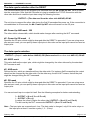
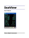
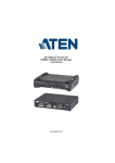
Free Application Software
Take advantage of the supplied free SW, either for configuring or for ideas for writing drivers.
Detailed description of the free subroutines, TEA encryption, and our NVT implementation is
available in the "Programming Ethernet Applications" document.
The
depicted
Web51
Charon demo terminal is a
simple
terminal
for
transferring data through
the
Windows
network
layer.
The program is available
with its source code Visual Basic 6.
According
to
the
checkboxes "DATA I/O
pins", the program mixes
a 6-byte control word that
sets the parallel outputs
into the data stream. It is
possible to control, for
example, a LED on the
parallel output of the I/O
Controller or the Charon I
module.
February 2003
HW server
page 16 / 18
Europe – Czech republic - Prague (Phone +420 222 511 918)
www.HWgroup.cz
RS232/485 <-> ETHERNET Converter
Some of our related products
RS232 - Ethernet Converter
Industrial version of our RS232 converter for TCP/IP or UDP/IP protocols. RS485 conversion module
is available. Configurable over UDP/IP or RS232.
•
•
•
•
•
All serial parameters configurable (50-115.200 Bd, 7-9
data bits, parity,)
Supports 9-bit transfer protocols
Secure configuration over the Ethernet
Support for an internal or external RS485 converter
(protocol detection, converter addressing, HW echo,
waiting for silence on half-duplex media, etc.)
Support for proprietary protocols can be added
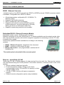
Embedded RS232 - Ethernet Converter Module
Embedded module, approx. 40x50 mm with 2x12 pins.
Ethernet connection on one side, RS232 and 8 TTL inputs controllable over the network on the other
side. Only the RJ45 connector with a built-in magnetic (supplied) for connecting a network TP cable
is outside of the module.
Continuously updated firmware available free of charge in the following
versions:
• RS232 – Ethernet Converter - described in this document
• SNMP – controls up to 64 remote I/O ports
• Empty (raw) version - user programmable, contains the I/O
Controller Lite
The module price is about half of the converter price!
Ethernet - serial Buffer 512 kB
Buffer with 512 kB of FLASH memory for data received from the serial line. Data can be read out
over the Ethernet using the TCP/IP protocol. If the buffer overflows, a warning e-mail is sent to the
operator.
• Secure reading of data from the buffer
• E-mail warning when buffer is filling up (two levels
corresponding to about 75% and 90% of capacity) or when
a power outage occurs
• 512 kB of FLASH memory with space compression
support
• Powerful remote configuration options, easy installation
February 2003
HW server
page 17 / 18
Europe – Czech republic - Prague (Phone +420 222 511 918)
www.HWgroup.cz
RS232/485 <-> ETHERNET Converter
Recommended literature and references
•
Programming Ethernet Applications (21 pages)
Detailed how-to for Ethernet application programming. Documented examples of the source
codes supplied with our devices. Description of the NVT and the TEA algorithms.
•
Charon I - datasheet (12 pages)
Datasheet for the Charon I web51 based modules. Contains in particular the electrical
parameters, connector descriptions, programming procedures, etc. Circuit diagram is available
for download at our website.
Detailed informations for every application (for example the RS232-Ethernet Converter) is not
part of this datasheet.
•
RS232 - Ethernet Converter
- Physical description of the "boxed" converter.
- Details and the SETUP description of the "RS232-Ethernet Converter" application available
for the "Charon I" modules as well.
•
WWW pages of the HW Group about final products: www.HWgroup.cz
•
For professionals and developers: Web51 Project - http://Web51.HW-server.com
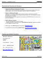
Contacts and detailed information
HW group (HW server)
Rumunska 26/122
Prague 2
120 00
Czech Republic - Europe
Phone : +420 222 511 918
Fax : +420 222 513 833
http://www.HWgroup.cz/
February 2003
HW server
page 18 / 18
Europe – Czech republic - Prague (Phone +420 222 511 918)
www.HWgroup.cz