1
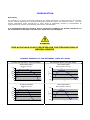
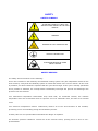
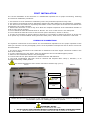
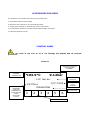
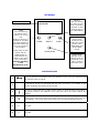
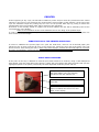
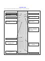
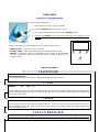
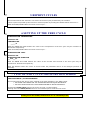
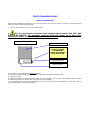
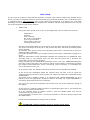
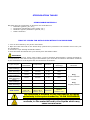
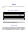
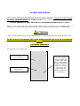
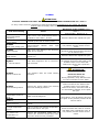
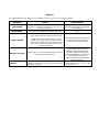
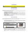
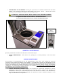
VERTICAL - Rev.4.1 - 2009.12.19
.
CONTENTS
CONTENTS ................................................................................................................................ 3
INTRODUCTION ........................................................................................................................ 4
GRAPHIC EXAMPLES OF THE DIFFERENT TYPES OF CYCLES ........................................................... 4
GENERAL WARNINGS ............................................................................................................... 5
PRESSURISED VESSEL ............................................................................................................. 5
SAFETY ..................................................................................................................................... 6
SAFETY SYMBOLS .................................................................................................................... 6
SAFETY DEVICES ..................................................................................................................... 6
PACKAGING, STORAGE AND DISPOSAL ..................................................................................... 7
DISPOSAL AND/OR DEMOLITION ............................................................................................... 7
FIRST INSTALLATION ............................................................................................................... 8
HYDRAULIC CONNECTIONS ....................................................................................................... 8
ACCESSORIES PROVIDED ......................................................................................................... 9
CONTROL PANEL....................................................................................................................... 9
DISPLAY ................................................................................................................................. 9
KEYBOARD ........................................................................................................................... 10
SERVICE ICONS .................................................................................................................... 10
PRINTER ................................................................................................................................ 11
SUBSTITUTION OF THE PRINTER PAPER ROLL ............................................................................ 11
PRINT HEAD CLEANING .......................................................................................................... 11
PRINTED STRIP ..................................................................................................................... 12
USER MENU ............................................................................................................................ 13
ACCESS TO THE USER MENU ................................................................................................... 13
MENU SEQUENCE .................................................................................................................. 13
1 LANGUAGE ..................................................................................................................... 13
2 TIME ............................................................................................................................. 13
3 DATE ............................................................................................................................. 13
4 SET-UP PRESSURE .......................................................................................................... 13
5 REPRINT CYCLES ............................................................................................................. 14
6 SETTING UP THE FREE CYCLE ........................................................................................... 14
7 TYPE OF END CYCLE PRESSURE DISCHARGE ....................................................................... 14
FIRST COMMISSIONING ......................................................................................................... 15
FIRST UTILIZATION ............................................................................................................... 15
TEST CYCLE .......................................................................................................................... 16
FREE CYCLE ............................................................................................................................ 17
FREE CYCLE PARAMETERS....................................................................................................... 17
TEMPERATURE ADJUSTMENT ................................................................................................... 17
STERILISATION TIME ADJUSTMENT.......................................................................................... 17
FAST DISCHARGE / SLOW DISCHARGE ..................................................................................... 17
STERILISATION TABLES ......................................................................................................... 18
STERILISABLE MATERIALS ...................................................................................................... 18
TABLE OF CYCLES FOR AUTOCLAVES WITHOUT VACUUM PUMPS .................................................. 18
TABLE OF CYCLES FOR AUTOCLAVES WITH VACUUM PUMPS ........................................................ 19
SPECIAL VERSION “LONG TIME” .............................................................................................. 19
NIGHT CYCLE ........................................................................................................................ 20
WATER QUALITY TABLE (DIN EN 285) .................................................................................... 20
BIOLOGICAL TEST .................................................................................................................. 20
ALARMS AND ERRORS ............................................................................................................ 21
ALARMS ............................................................................................................................... 22
ERRORS ............................................................................................................................... 24
MAINTENANCE ....................................................................................................................... 25
DAILY MAINTENANCE ............................................................................................................. 25
WEEKLY MAINTENANCE .......................................................................................................... 25
QUARTERLY MAINTENANCE ..................................................................................................... 26
ANNUAL MAINTENANCE .......................................................................................................... 26
TECHNICAL CHARACTERISTICS .............................................................................................. 27
GUARANTEE............................................................................................................................ 28 THE MANUFACTURER RESERVES THE RIGHT TO MODIFY THIS MANUAL WITHOUT NOTICE. THIS MANUAL
IS THE EXCLUSIVE PROPERTY OF THE MANUFACTURING FIRM: ANY REPRODUCTION OR TRANSFER TO
THIRD PARTIES WITHOUT AUTHORISATION IS PROHIBETED AS PROVIDED FOR BY LAW.
INTRODUCTION
Dear Client,
The autoclave is a device specifically studied for the steam sterilisation of tools and soils. It is broadly
used in research laboratories, in facilities dedicated to personal hygiene and veterinary clinics. The very
specific sterilisation loads encountered in these areas of application demand a diversification of
requirements with respect of sterilisation performance characteristics.
It is fundamental that the steriliser and its respective equipment are utilised exclusively for
the sterilisation of the types of products for which they were designed.
ATTENTION
THIS AUTOCLAVE IS NOT CERTIFIED FOR THE STERILISATION OF
MEDICAL DEVICES
GRAPHIC EXAMPLES OF THE DIFFERENT TYPES OF CYCLES
AUTOCLAVE WITHOUT VACUUM PUMP
1,2
AUTOCLAVE WITH VACUUM PUMP
SLOW DISCHARGE
without vacuum
1,5
1,10
1,10
1
1
dry
0,8
Pressure (Bar)
Pressure (Bar)
FAST DISCHARGE
with ultimate vacuum
0,6
0,4
dry
0,5
0
0,2
0
-0,5
Time
1,2
Time
SLOW DISCHARGE
without vacuum
1,5
1,10
1,10
1
1
0,8
Pressure (Bar)
Pressure (Bar)
FAST DISCHARGE
with ultimate vacuum
0,6
0,4
dry
0,2
0
dry
0,5
0
-0,5
Time
Time
GENERAL WARNINGS
It is suggested that this manual be read thoroughly and with care before beginning to utilise the device
in such a way as to carry out the required operations in an appropriate manner: DO NOT carry out,
therefore, operations different from those found in this booklet. The manufacturing firm declines any and
all responsibility for either direct or indirect damages to things, persons or animals stemming from the
inappropriate use of this equipment.
•
It is recommended that only responsible adult individuals use this equipment.
•
Position the machine in a place inaccessible to children.
•
Position the autoclave in such a manner that access to the main power switch is easy and practical.
•
Install the device in a manner that an electric power outlet is easily accessible.
•
Do not use the machine close to sources of inflammable or explosive materials.
•
Utilise the machine in protected and dry environments.
•
Periodically check the condition of the electric power cord: do not start the machine when the power
cord is not perfectly integral.
•
Do not carry out maintenance tasks when the machine is in operation or connected to the power
outlet.
•
Do not approach the machine while carrying inflammable material.
•
Always wear personal safety devices and apparel, with respect of the current laws in force.
•
Do not utilise this device for reasons other than those found in this instruction manual.
•
Read the paragraph relative to the machine’s technical characteristics before putting it into operation.
•
For your personal safety we ask you to pay great attention to the instructions that follow herein.
PRESSURISED VESSEL
The Pressurised vessel (sterilisation chamber) is an integral part of the autoclave, therefore it is necessary
to adhere to, apart from the general warnings found above, specific cautions:
•
•
•
•
Position the autoclave in such a manner that the safety valve (located in the back part of the
machine) will not create any type of problem or disturbance in the event of a release of pressure.
Do not interfere in any manner with the safety valve: any maintenance activity must be performed
exclusively by personnel authorised by the manufacturing firm.
Do not insert any tool that may damage the sterilisation chamber.
Do not sterilize any corrosive liquid or substance.
SAFETY
SAFETY SYMBOLS
ATTENTION CAREFULLY READ THE
INSTRUCTIONS FOUND IN THE USER
MANUAL
TENSION
BEWARE OF HIGH TEMPERATURE
GROUND CONNECTION
ATTENTION BEWARE OF HAND
CRUSH HAZARD
SAFETY DEVICES
The safety devices foreseen are the following:
Three micro-switches in the hatchway and automatic locking system: they are independent each from the
other and they verify that the hatchway system is closed and locked in the correct manner. In the event
of problems, an alarm notifies the operator that the cycle cannot begin. If the cycle is already operational
and a problem is detected, the microprocessor immediately interrupts the process and discharges the
pressure from the machine.
Two mechanical temperature thermostats keep check that, for accidental reasons, the machine
temperature does not exceed that which is required: one is for automatic reset, the other is for manual
reset.
Two electronic temperature sensors continuously monitor all of the vital functions of the machine,
preventing errors of overheating during the sterilisation process.
A safety valve for over-pressurisation eliminates the danger of explosion.
An electronic pressure transducer controls all of the solenoid valves, opening them in case of overpressurisation.
PACKAGING, STORAGE AND DISPOSAL
The cardboard packaging utilised for transport of the autoclave IS NOT STERILE.
The autoclave is a delicate piece of equipment, therefore it is to be transported without receiving
excessive shocks, collisions or without being OVERTURNED.
The autoclave is packaged with its accessories enclosed in the boiler. It is positioned inside the carton
surrounded by a protective polyethylene bag. In order to protect it from accidental shocks it is
surrounded as well by polystyrene or cardboard forms.
Keep in a protected, dry environment at a temperature between 5° and 30° C.
The client is invited to keep the original packaging for the guarantee period: any eventual returns for
repair without the original packaging will be charged for new packaging at the moment of restitution.
Extraction and positioning of the Autoclave.
The operation of extraction of the machine from the cardboard carton must be carried out by at least two
people, following the cautions listed below:
•
Cut the straps that bind the cardboard carton.
•
Open the cardboard carton and remove the metallic sealing staples so as to not be scratched.
•
Remove the machine, grasping it by its sides, without putting load on the plastic parts.
•
Read the instructions for use.
•
Connect the plug to a Schuko socket furnished with a safety ground connection.
Do not substitute the original plug with others.
Do not use additional or extension connections.
Do not connect to multiple outlets or other types.
Be sure that the electrical plant to which the autoclave is connected is up to standard based upon the
norms in force and that it is able to withstand the electrical load required.
•
Turn on the machine with the main switch located on the side of the control panel.
•
Open the hatch pushing on the button marked DOOR.
•
Remove the accessory kit and turn off the machine.
•
CAREFULLY READ THE USER MANUAL BEFORE BEGINNING ROUTINE WORK.
DISPOSAL AND/OR DEMOLITION
For disposal and/or demolition of any component (packaging, water, any machinery…) scrupulously keep
to the norms in force in the country in which this operation is carried out.
FIRST INSTALLATION
The correct installation of the autoclave is a fundamental operation for its proper functioning. Following
are listed the installation procedures:
1. The machine is to be installed in a laboratory where only authorised personnel may enter.
2. The working environment must be adequately lighted (see UNI 10380 norm) and sufficiently ventilated.
3. The device is to be located on a perfectly flat surface. Leave a free space of at least 20 cm between the
wall and the rear of the autoclave.
4. Position the autoclave in such a way as to allow the complete inspection of the sterilisation chamber in
order to carry out its cleaning.
5. Do not install the autoclave beside sinks or faucets: The cover of the device is not waterproof.
6. Do not install the autoclave next to heat sources (other autoclaves, stoves or others).
7. In order to avoid harm to people, things or animals, it is necessary to position the device in such a way
as to permit any eventual outflow coming from the safety valve, which is to be released in a safe area.
HYDRAULIC CONNECTIONS
The hydraulic connections of the machine are of fundamental importance for the proper operation of the
same (for reference see the photograph) and to avoid unpleasant consequences due to burns. Proceed as
described below:
1. The silicon hose connected to the small tank is attached to the hose nipple connection located in the
back of the machine.
2. In some cases there are two hoses: these are attached to the two threaded nipples present.
3. Adhere to the information found in the photograph.
4. Leave at least 20 cm space between the machine and the wall behind it.
5. The small condensation trap tank must be checked and emptied often: Keep it, therefore, in an
accessible and easily visible position.
6.
The steam temperature at the outlet connection could be high (70° C).
PHOTO 1
PHOTO 2
Fuses
Threaded
nipple con.
Condensation
tank
RS232 data port for the connection of the “Datalogger” system: useful for the electronic recording of
the machine cycles. The “Datalogger” system is optional.
2.
IMPORTANT NOTES:
1. Empty the condensation tank often.
DO NOT TOUCH THE THREADED NIPPLE CONNECTIONS DURING STEAM DISCHARGE.
3. Allow at least 20 cm from the back panel to the wall to permit air circulation.
ACCESSORIES PROVIDED
The autoclave is furnished with the following accessories:
1. Perforated stainless steel basket.
2. Stainless steel support for the perforated basket.
3. Yellow/green sponge for cleaning the inside of the boiler.
4. Condensation container provided with threaded nipple connection.
5. Hatch adjustment wrench.
CONTROL PANEL
Do not use tools of any sort so as to not damage the display and its external
protection.
DISPLAY
PRESSURE PRESENT IN
STERILISATION
CHAMBER.
STERILISATION
CHAMBER
TEMPERATURE
103.9°C
0.12bar
TYPE OF CYCLE
SELECTED
121° fast dis.
c/n°:0142
18:37min
CYCLE TIME
REMAINING
(FROM THE
BEGINNING OF
STERILISATION
PHASE
INCLUDING
DRYING)
PREHEATING
1
2
3
4
5
6
SERVICE ICONS
PROGRESSIVE
CYCLE
COUNTER
ACTIVE PHASE
OF THE CYCLE
KEYBOARD
SELECT
With this button
the type of cycle
that is needed is
selected. It also
gives access to
the USER MENU.
Display
DOOR
Used for opening
the hatch of the
machine at end of
cycle.
Holding it down it is
possible to visualise
the total plateau of
STR+DRY times and
the cycle counts of
the machine.
If the hatch is held
closed and the
DOOR button is
depressed for at
least 5”, the hatch
lock is activated
without initiating
a new
sterilisation cycle.
DOOR
SELECT
PUMP
PUMP
This is used
exclusively for
setting the set-up
values of the
USER MENU and
of the FREE
CYCLE.
START/STOP
START/STOP
Initiates cycle.
During cycle, if
pressed for more
than 1 second,
interrupts cycle.
SERVICE ICONS
1
This icon appears immediately after the initiation of the cycle and indicates that
the machine hatch is locked.
2
The presence of this icon indicates that the cycle is running: it is possible to also
see the rotational movements of the arrows.
3
Icon No. 3 signals the lack of paper in the printer or, that the door to the same is
not properly closed. The machine can in any case carry out cycles without any
damage.
4
V
The letter “V” indicates that the selected cycle, after the final discharge, is
carrying out a forced removal of the steam by way of the vacuum pump (see the
cycle graphs). The cycles without this letter carry out thermodynamic drying.
5
n.i.
Not used
6
n.i
Not used
PRINTER
At the beginning of any cycle, the autoclave initiates a printer strip on which are printed all of the values
inherent in the type of cycle selected, the model and the serial number of the machine. At the end of the
cycle the autoclave stops the printing strip as well: cut the printed data strip by pulling it toward the
metallic blade (the incorporated cutter will be useful for this operation).
If the door is not correctly closed or if paper has not been loaded, the user will be notified by the service
icon appearing in the display.
Refer to the indications of the Local Health Service for the filing of the printed strips.
In order to maintain the printed strips for an ample duration of time, they must be filed in a place free
from excessive heat and light.
SUBSTITUTION OF THE PRINTER PAPER ROLL
In order to substitute the printer paper roll: open the small door, insert a roll of thermal paper (the
maximum size of which must be 56 mm) in the proper slot, having the free end of the paper come out
above the door while closing the same. Utilize only thermal paper. Position the thermal paper in its proper
direction of orientation: overturning the paper, the printed strip will come out blank.
PRINT HEAD CLEANING
If the print on the strip is difficult to read the print head needs to be cleaned, using a cloth dampened
with alcohol: open the small door to the printer, extract the roll of paper and clean the print head (see the
highlighted points in the photo). Blow away the dust deposited inside the printer with air.
The print head is found just underneath
the cutter blade. Carry out cleaning
operations with the machine off.
The thermal paper must come out above
this roller.
If the door is not closed properly or if
paper is needed, the service icon will
flash on the display.
PRINTED STRIP
Correct reading and interpretation of the information on the printed strip:
Model name.
Software version.
Serial number.
Cycle type selected.
Time column: hour, minutes
and seconds.
Date of cycle initiation.
Progressive number of
cycles initiated.
Characteristics of cycle
initiated. Temperature
and minimum pressure
are marked.
Active phases of cycle.
Temperature column
expressed in degrees
centigrade (°C).
Space for operator’s
signature.
Pressure column
expressed in bar (relative
pressure).
Cycle results.
USER MENU
ACCESS TO THE USER MENU
To access the user menu proceed as described below:
1.
Open the door and turn off the machine.
2.
Press the SELECT button and hold it down
3.
Turn on the machine by way of the main ON/OFF switch.
4.
Release the SELECT button only after “language set” appears on the
display.
Inside of the user menu the buttons are to be used in this manner:
• START/STOP = moves up to the next page.
• DOOR e PUMP = allow the modifications of settings inside the page.
• SELECT = pushing it until the confirmation tone is heard, it will memorize
the pre-selected value (not all of the pages require the memorisation of preselected values).
DOOR
SELECT
PUMP
START/STOP
MENU SEQUENCE
1 LANGUAGE
ITALIAN/ENGLISH/……
it is possible to select the language utilising the DOOR and PUMP buttons.
2 TIME
FORMAT
hh
mm
ss
In this page the time is set. With the DOOR button the value is increased, with PUMP it is decreased and
with the SELECT button the cursor is moved under the value to be modified. With the START/STOP button
the screen moves up to …
3 DATE
FORMAT
dd
mm
yr
In this page the date is set. With the DOOR button the value is increased, with PUMP it is decreased and
with the SELECT button the cursor is moved under the value to be modified. With the START/STOP button
the screen moves up to …
4 SET-UP PRESSURE
PRESSURE atm
_ . _ _ _ bar
The machine automatically carries out the set up of atmospheric pressure. It is not possible to interfere in
any manner. With the START/STOP button the screen moves up to …
5 REPRINT CYCLES
REPRINT CYCLES
This function allows the archival in one action of the last cycles performed by the machine.
These cycles are printed by the internal or external printer by holding the SELECT button down for 5”.
With the START/STOP button the screen moves up to …
6 SETTING UP THE FREE CYCLE
STERILISATION TEMPERATURE:
CYCLE No. 08
TEMPERATURE
___._°C
With the DOOR and PUMP buttons the value of the temperature of the free cycle may be increased or
diminished respectively.
With the START/STOP button the screen moves up to …
STERILISATION TIME:
CYCLE No. 08
STERILISATION DURATION
__mm.__ss.
With the DOOR and PUMP buttons the value of the minutes and seconds of the free cycle may be
increased or diminished respectively.
With the SELECT button the cursor is moved under the parameter that is to be changed (minutes or
seconds).
With the START/STOP button the screen moves up to …
7 TYPE OF END CYCLE PRESSURE DISCHARGE
FAST DISCHARGE / SLOW DISCHARGE
This function allows the choice of the method of the final discharge in the FREE CYCLE.
> SET SLOW DISCHARGE FOR THE STRERILISATION OF LIQUID MATERIALS.
> SET FAST DISCHARGE FOR THE STRERILISATION OF SOLID MATERIALS.
Pushing the START/STOP returns the screen to point 1 of this chapter.
Holding down the START/STOP button for an extended period exits the user menu.
At any moment it is possible to exit from the USER MENU mode
holding down the START/STOP button for an extended period.
FIRST COMMISSIONING
FIRST UTILIZATION
After having installed the autoclave, the correct function of the device must be verified. Proceed however
utilizing certain cautions found below:
1. Turn on the machine by way of the main switch.
Fill the sterilisation chamber with demineralised water (DO NOT USE
DISTILLED WATER). The chamber must be filled with water up to where the
resistance heater is completely covered by the water.
2.
Sterilisation chamber
Perforated basket
Correct water level.
DO NOT UTILIZE
THE MACHINE
WITH LESS WATER
THAN SPECIFIED
Resistance heater
Basket support
3. Choose the cycle utilising the SELECT button.
4. Remove the basket and fill the sterilisation chamber with demineralised water:
5. Close the hatch.
6. Holding the hatch pushed downward, start the pre-selected cycle by way of the START button (release
the hatch only after the closed door icon appears on the display.
7. The autoclave will continue automatically up to the end of the cycle, signalled by a triple tone and by
the message END CYCLE on the display.
TEST CYCLE
The test cycle is needed to verify that the autoclave is integral, that it hasn’t suffered any damage during
delivery or that, for technical reasons it doesn’t present any operational problems. As a verification test, it
is suggested that a rapid discharge cycle be set. Below the functioning of a sample free cycle (fast
discharge) is described, in such a way that simplifies the utilisation and the comprehension of the carrying
out of the operational cycles of the machine:
•
FREE CYCLE
During the entire period of the cycle, on the display there will be visible the values of:
temperature
pressure
time remaining
No. of the cycle initiated
type of cycle initiated
active phase of the cycle
eventual warning icons
Insert the perforated basket into the machine, close the hatch and push the START button.
The printer will begin the first part of the printed strip after which the preheating phase
will be initiated.
In machines with vacuum pump, this preheating phase may be preceded by a brief preemptying phase (VACUUM).
During the operation of the cycle a light humming of the water condensation cooling fan is
heard.
When the temperature of the sterilisation chamber has reached the pre-established value
(normally 105° C), the solenoid valve will close and the actual rise in pressure and
temperature of the machine will begin.
Having reached the pre-established parameters of the cycle, the STERILISATION phase
will begin. During this phase, the electronic system of the machine continuously monitors
the pressure and temperature values, intervening, where necessary, to re-establish the
correct procedure of the cycle.
In an extreme case, the software intervenes to block the cycle signalling an ALARM.
At the end of the sterilisation phase the solenoid valve will open so as to permit the
outflow of steam toward the cooling system and, afterward, toward the condensation tank
(DISCHARGE).
This phase may be SLOW or FAST: it is suggested that “SLOW DISCHARGE” be set if
liquids in their own appropriate containers must be sterilised; set “FAST DISCHARGE” if
exclusively solid materials are to be sterilised.
The end of the cycle will be signalled by an acoustic tone and by the respective writing on
the display.
In the event of a residual negative pressure or temperature above 94° C, the machine will
not permit the opening of the hatch.
If in the chamber there is negative pressure, push the DOOR button and wait for
equalisation then open the hatch.
If the temperature is above 94° C, wait for the machine to cool then open the hatch with
the DOOR button.
Extract the perforated basket, lifting it with its handle:
ATTENTION: utilize protective gloves to avoid serious burns.
FREE CYCLE
THE FREE CYCLE is utilised for particular laboratory applications. All of the parameters that
may be set in the “FREE CYCLE” must be modified exclusively by specialised personnel.
FREE CYCLE PARAMETERS
To access the FREE CYCLE parameters see the chapter USER MENU.
TEMPERATURE ADJUSTMENT
It is possible to set the temperature from 105 ° C to 135° C. When the display shows
CYCLE No. 08
TEMPERATURE
000.0°C
it is necessary to use the DOOR button to increase the value and the PUMP button to decrease it. Having
found the desired value, hold down the START button for an extended period in order to exit the program
or else push the START button one time to go into…
STERILISATION TIME ADJUSTMENT
It is possible to set the sterilisation time from 1 to 90 minutes (89 minutes and 59 seconds). When the
display shows
CYCLE No. 08
DURATION OF STERILISATION
00.00 (mm.ss)
it is necessary to use the DOOR button to increase the value and the PUMP button to decrease it. The
SELECT button allows the cursor to be moved to the parameter to be modified (minutes or seconds).
In the special “Long Time” version the duration of the RUNNING phase may vary from 1 minute to 59.999
minutes.
Having found the desired value, hold down the START button for an extended period in order to exit the
program or else push the START button one time to go into the choice between…
FAST DISCHARGE / SLOW DISCHARGE
It is necessary to push the DOOR button to change the type of final steam discharge: utilise the “SLOW
DISCHARGE” if the intention is to sterilise liquids. Having set the desired value, hold the START button
down for an extended period to exit the program.
ATTENTION
Utilise the “SLOW DISCHARGE” if the intention is to sterilise liquids.
Once the desired value has been set, turn off the machine to exit the user menu.
STERILISATION TABLES
STERILISABLE MATERIALS
Normally this type of autoclave is utilised for the sterilisation of:
•
Glassware (glasses, jars, etc.);
•
Products for Microbiology (soils, broths, etc.);
•
Metalware (spoons, flatware in general, etc.)
•
Plastic containers
TABLE OF CYCLES FOR AUTOCLAVES WITHOUT VACUUM PUMPS
1. Turn on the machine by way of the main switch.
2. Open the hatch and wait for the double beep (without this “permission” the machine will not carry out
any operations).
3. Choose the cycle utilising the SELECT button.
4. Close the hatch and initiate the cycle directly from the START button.
ATTENTION
Before sterilising any tool, liquid, solid or fabric, verify its technical characteristics, normally specified by
its manufacturer. The choice of the type of sterilisation cycle must also be based on information furnished
by the manufacturer of the objects that are intended for sterilisation.
Minutes of
Sterilisation
Temperature
Pressure
Type of
Discharge
15.00
121.0°C
1.10
Fast
15.00
121.0°C
1.10
Slow
20.00
121.0°C
1.10
Fast
20.00
121.0°C
1.10
Slow
4.00
134.0°C
2.10
Fast
4.00
134.0°C
2.10
Slow
134° PRION
18.00
134.0°
2.10
Fast
FREE CYCLE
Min: 1’
Max: 90’
Default: 20’
Min: 105°C
Max: 135°C
Default: 110°C
Automatic
Options
Default: Fast
Type of Cycle
121°C
Fast Discharge
121°C
Slow Discharge
121°C
Fast Discharge
121°C
Slow Discharge
134°C
Fast Discharge
134°C
Slow Discharge
Load
Maximum
6 kg
If solid materials
or else
5 kg
if liquid products
The autoclave is enabled for the sterilisation of liquids
exclusively in the cycles headed by “SLOW DISCHARGE”
When opening the hatch, give maximum attention to the
surfaces, to the materials and to the liquids which may
cause severe burns
TABLE OF CYCLES FOR AUTOCLAVES WITH VACUUM PUMPS
1. Turn on the machine by way of the main switch.
2. Open the hatch and wait for the double beep (without this “permission” the machine will not carry out
any operations).
3. Choose the cycle utilising the SELECT button.
4. Close the hatch and initiate the cycle directly from the START button.
ATTENTION
Before sterilising any tool, liquid, solid or fabric, verify its technical characteristics, normally specified by
its manufacturer. The choice of the type of sterilisation cycle must also be based on information furnished
by the manufacturer of the objects that are intended for sterilisation.
Type of Cycle
121°C
Fast Discharge
121°C
Slow Discharge
121°C
Fast Discharge
121°C
Slow Discharge
121°C
Fast Discharge
121°C
Slow Discharge
121°C
Fast Discharge
121°C
Slow Discharge
FREE CYCLE
LEGEND:
Minutes of
Sterilisation
Temperature
Pressure
Type of
Discharge
Empty of
Dry
15.00
121.0°C
1.10
Fast
15.00
121.0°C
1.10
Slow
15.00
121.0°C
1.10
Fast
15.00
121.0°C
1.10
Slow
20.00
121.0°C
1.10
Fast
20.00
121.0°C
1.10
Slow
20.00
121.0°C
1.10
Fast
20.00
121.0°C
1.10
Slow
X
X
√
√
X
X
√
√
Min: 1’
Max: 90’
Default: 20’
Min: 105°C
Max: 135°C
Default: 110°C
Automatic
Options
Default:
Fast
Load
Maximum
6 kg
If solid materials
or else
5 kg
if liquid products
√
√= Present (letter V present on display) X = Absent (no letter on display)
The autoclave is enabled for the sterilisation of liquids
exclusively in the cycles headed by “SLOW DISCHARGE”
When opening the hatch, give maximum attention to the
surfaces, to the materials and the liquids which may
cause severe burns
SPECIAL VERSION “LONG TIME”
Special autoclaves called “Long Time” have a FREE CYCLE with the possibility of expanding the exposition
time (RUNNING) up to 59.999 minutes.
Type of Cycle
Minutes of
Sterilisation
Temperature
Pressure
Type of
Discharge
FREE CYCLE
Min: 1’
Max: 59.900’
Default: 20’
Min: 105°C
Max: 135°C
Default: 110°C
Automatic
Options
Default: Fast
Load
Maximum
6 kg
If solid materials
or else
5 kg
if liquid products
NIGHT CYCLE
If there are no operations to be carried out on the autoclave, this cycle reduces the consumption of
energy keeping lit only the display backlight. Pushing any button (except START/STOP) the display will
show the results of the last operation carried out (for ex. END CYCLE). Any cycle may become a “night
cycle”.
WATER QUALITY TABLE (DIN EN 285)
CEN STANDARD DIN EN 285
Evaporation residue
Silicon oxide (SiO2)
Iron
Cadmium
Lead
The rest of the heavy metals (except iron, cadmium and
lead)
Chloride
Phosphate
Conductivity (at 20° C)
pH value
Aspect
Hardness
Maximum value
10 mg/l
1 mg/l
0,2 mg/l
0,005 mg/l
0,05 mg/l
0,1 mg/l
2 mg/l
0,5 mg/l
15 µS/cm
from 5 to 7
Colourless, clean and with no
sediment
0,02 mmol/l
NOTE: The use of feed water containing concentrations superior to those indicated in
the table above may notably reduce the life of the device causing serious damage to its
components and leading to the forfeiture of the guarantee.
BIOLOGICAL TEST
Together with other chemical tests a biological test may also be requested. This test consists in the
sterilisation of one or more vials containing biological spores, together with a normal sterilisation load. At
the end of the initiated cycle, remove the vials and allow them to cool for some minutes (keep to the
manufacturers instructions for the control procedures). Normally the sterilised vials are broken, using the
instruments provided by the manufacturer, and inserted in a specific incubator: together with these
another, as control, that has not undergone the process of sterilisation. After the incubation period, the
difference in colour of the sterilised vials determines the result of the cycle.
ALARMS AND ERRORS
Alarms remain visualised on the display and block any further operations: they are also recorded on the
printed strip: after an alarm it is necessary to carry out the reset by contemporaneously pushing
the START and SELECT buttons for at least 5 seconds.
IT IS NOT POSSIBLE TO RESET AN ALARM IF THE INTERNAL TEMPERATURE IS > 94.0° C
Errors, on the other hand, do not permit the initiation of the cycle but give the warning that it is
necessary to carry out an operation before initiating the sterilisation procedure (for ex. “DOOR OPEN”).
ATTENTION
Any cycle not completed is to be considered ineffective: on the display there will appear an alarm code.
In the event of an alarm, the cycle being carried out is to be considered
invalid
(unsterile material).
Interpretation of an ALARM code:
Characteristics of the
cycle initiated.
Alarm indication (in this
case AL0001).
After the alarm code
all of the machine
values recorded are
printed: date, time
sensor temperatures,
pressure and electric
tension. In case of
alarm, it is a good
idea to keep the
printed strip for a
simpler resolution of
the problem.
ALARMS
ATTENTION:
IT IS NOT POSSIBLE TO RESET AN ALARM IF THE INTERNAL TEMPERATURE IS > 94.0° C
To carry out the reset it is necessary to push and hold down simultaneously the START and SELECT
buttons until the display shuts off momentarily.
Code and meaning
AL0001
Cycle interrupted
voluntarily
AL0002
Power failure
Resolution of the problem: Reset
alarm =
START/STOP + SELECT for 5”
Cause
This occurs if the START/STOP button is
pushed for more than 1 second.
Caused by the lack of electric power
AL0003
Door open during cycle
This occurs if one of the door control
micro-switches detects
“door open
during cycle”.
AL0004
Timer stopped
May occur if the battery in the electronic
data card is drained.
AL0005
High tension
Caused by an overload of the electric
power line.
AL0011
1st vacuum failure
Reset the alarm then repeat the cycle.
st
This alarm appears if the 1
not achieved.
vacuum is
Reset the alarm then repeat the cycle: If
the problem persists call the service
centre
Reset the hour and date Before
utilisation leave the autoclave turned on
for at least an hour.
Reset the alarm then repeat the cycle.
Reset the alarm, adjust the hatch, clean
the gaskets and insure that inside of the
chamber there are no sacks that
obstruct the ducts, then repeat the
cycle.
ATTENTION:
AL0024
Failure of final rise
AL0034
Final discharge failure
AL0100
Codification sensor T1
error
AL0101
OPEN T1
AL0102
Short circuit T1
AL0110
T1 high temperature
sensor
AL0111
T1 sensor Low
temperature in
sterilisation
The machine does not reach working
pressure.
During the drying phase the machine
does not discharge pressure.
The alarm is the result of electronic
data-card self diagnosis
T1 sensor reads open.
SEVERE BURN HAZARD
Check the water fill
then repeat the cycle.
During operation, verify that there are
no losses of steam from the hatch.
Reset the alarm, remove the basket and
make sure that on the inside of the
chamber there are no sacks that
obstruct the ducts, clean the inside of
the sterilisation chamber, then repeat
the cycle.
Reset alarm. Turn off machine and turn
on again: If the problem persists call the
service centre.
The T1 sensor is detected in short
circuit.
The T1 sensor has detected temperature
above that set for the cycle.
During the sterilisation phase the T1
sensor has detected temperature lower
than the minimum limit permitted.
Reset the alarm then wait 10 minutes
with hatch open. Repeat the cycle: If
the problem persists call the service
centre.
AL0200
Codification sensor T2
error
AL0201
OPEN T2
AL0202
SHORT CIRCUIT T2
AL0210
T2 high temperature
sensor
AL0211
T2 sensor Low
temperature in
sterilisation
AL0300
Codification sensor P
error
AL0301
OPEN P
AL0302
SHORT CIRCUIT P
The alarm is the result of electronic datacard self diagnosis
T2 sensor reads open.
Reset alarm. Turn off machine and turn
on again: If the problem persists call
the service centre.
The T2 sensor is detected in short circuit.
The T2 sensor has detected temperature
above that set for the cycle.
During the sterilisation phase the T2
sensor has detected temperature lower
than the minimum limit permitted.
The alarm is the result of electronic datacard self diagnosis
P sensor reads open.
Reset the alarm then wait 10 minutes
with hatch open. Repeat the cycle: If
the problem persists call the service
centre.
Reset alarm. Turn off machine and turn
on again: If the problem persists call
the service centre.
The P sensor is detected in short circuit.
AL0310
High pressure in
sterilisation
During the sterilisation phase the P
sensor has detected pressure higher than
the maximum limit permitted.
AL0311
Low pressure in
sterilisation
During the sterilisation phase the P
sensor has detected pressure lower than
the minimum limit permitted.
AL0700
Comparison T1 / T2
During sterilisation the two internal
sensors
have
detected
discordant
temperature readings
Reset the alarm, remove the basket
and make sure that on the inside of the
chamber there are no sacks that
obstruct the ducts, clean the inside of
the sterilisation chamber, then repeat
the cycle.
Reset alarm. Clean the gaskets and
repeat the cycle: If the problem
persists,
it is necessary to call the service
centre.
Reset the alarm then repeat the cycle:
If the problem persists call the service
centre.
ERRORS
The messages that may appear on the display in the event of error are the following:
MESSAGE
CAUSE
RESOLUTION
OPEN DOOR
At start up it is requested that the hatch be
opened to permit the machine to carry out its
pressure check-up.
DOOR OPEN
A cycle has been initiated with the hatch open.
Open the hatch to permit
automatic barometric alignment
(double beep).
Close the hatch and initiate the
cycle.
The hatch has been released too quickly,
after having started initiation of the cycle.
LOCK FAILURE
UNLOCK FAILURE
SERVICE
Regardless of the perfect closure of the
hatch, it is read as being “not locked” for
mechanical reasons (the repetition of this
error code requires the intervention of an
expert technician.).
Push the DOOR button, open and
re-close the hatch, initiate the
cycle with the START button.
Re-close the hatch initiating a new
cycle: after a few seconds,
interrupt it with START/STOP,
reset the alarm and open the
At the end of a cycle the hatch locking system
hatch with DOOR for verification.
does not open completely.
The repetition of this error
requires the intervention of an
expert technician.
The machine has carried out an elevated As soon as possible contact your
number of cycles and requires a service call for reseller and request a service call
by a technician.
a periodic overhaul.
MAINTENANCE
Before any maintenance operation it is obligatory that the electric power source to the
device be disconnected.
DAILY MAINTENANCE
Daily maintenance foresees the topping up of the water level, cleaning of the edge of the boiler and the
maintenance in good condition of the hatch gasket.
•
•
•
•
TOPPING UP OF THE WATER LEVEL: the water level inside the chamber must always be even
with the bottom of the perforated basket.
BOILER EDGE: is the external edge of the sterilisation chamber on which the gasket makes a
seal. Utilise the rough part of the sponge furnished in the kit.
HATCH GASKET: clean the hatch gasket using the soft part of the sponge furnished in the kit.
Cleaning must be carried out to remove any eventual debris that could impede the full operational
completion of cycles.
GENERAL CLEANING OF THE SURFACES: utilize a cloth for removal of dust and deposits from
the different upper parts of the machine.
WEEKLY MAINTENANCE
Weekly maintenance foresees the total substitution of the sterilisation chamber water, visual inspection of
the inside of the chamber and the check of a proper seal on the hatch gasket.
•
TOTAL WATER SUBSTITUTION Utilising the condensation container, empty the sterilisation
chamber by opening the spigot below (see photo). Remove the perforated basket to ascertain the
total emptying of the chamber. Then proceed to the…
DO NOT CARRY OUT THIS OPERATION WITH
LIVE MACHINE, DURING A CYCLE OR WITH
PRESSURE IN THE CHAMBER!
Discharge tap: use the condensate container to
empty the chamber from water.
ATTENZION: SCALD DANGER
•
CLEANING OF THE INSIDE OF THE CHAMBER: clean the inside of the sterilisation chamber
utilising the rough part of the sponge, provided in the kit, to remove small impurities in the
bottom of the chamber. Any limescale deposits require a verification of the water that is being
used.
•
PROPER SEAL OF THE GASKET if during the cycle there is a release of steam from the hatch
gasket, it is necessary to adjust the hatch hinges in a uniform manner. Utilising the wrench
provided in the kit, adjust the hinges in the following manner:
ATTENTION: ALWAYS ADJUST BOTH HINGES IN A UNIFORM MANNER.
-
to tighten the hatch screw down in a clockwise direction
to loosen the hatch unscrew in a counter-clockwise direction
HINGES
Wrench for
hatch
adjustment
QUARTERLY MAINTENANCE
Quarterly maintenance foresees the lubrication of the hatch hinges.
•
HINGE LUBRICATION:
hinges.
utilize silicone oil, spraying it, in small quantities, on the two hatch
ANNUAL MAINTENANCE
The autoclave is a fundamental tool for the safeguarding of one’s work: even though the electronic
controls of these machines are always more reliable, it is well advised to perform an operational check of
the device at least once a year. This check must be performed only by authorised and specialised service
centres, with calibrated and certified instruments, so as to guarantee the machine long life and reliability
(validation). To determine the control methods for the machine, it is, in any case, incumbent to refer to
the indications of the local public health service.
•
ANNUAL VALIDATION: Validation foresees the utilisation of instruments calibrated by centres
specialised in the check of the parameters of autoclave cycles. Indeed, the pressure and
temperature sensors are verified and the timer of the machine is checked. The manufacturer,
upon request, provides an annual certificate of inspection for those machines brought in to its
shop for maintenance and inspection.
TECHNICAL CHARACTERISTICS
MECHANICAL SPECIFICATIONS
Operational temperature
Maximum operational altitude
Maximum relative humidity at 30° C
Maximum relative humidity at 40° C
Maximum dimensions (H x W x D)
Open hatch clearance
Weight
Colour
Material
Noise level at 1 m distance
Noise level in front of display
ELECTRIC SPECIFICATIONS
Electric power tension
Power rating
Frequency
Power cord (L 1.5 m)
Fuses
Maximum heat transmission
Insulation class
CHAMBER SPECIFICATIONS
Maximum operational pressure
Maximum operational vacuum
Maximum operational temperature
Material
Dimensions (diam. x depth)
STEAM / DISCHARGE WATER SPECIFICATIONS
Steam temperature near the threaded nipple connection
Steam temperature near the condensation tank
POLLUTION LEVEL
+5° +30° C
2000 m
80%
50%
930 x 460 x 395 mm
350 mm
55 Kg
RAL9002
Stainless Steel AISI 304
/FeP01
53,6 dbA
62,2 dbA
230 Vac (+/-10%)
2500 W
50-60 Hz
2+1 x 1,5mm
6,3x32mm – T12A
5,76 MJ/h (1370 Kcal/h)
1
2.3 bar relative
-0.80 bar relative
140°C
Stainless Steel AISI 304
236,5 x 530 mm
56°C
50°C
2
GUARANTEE
For all defects in conformity existent at the moment of delivery of the device and imputable to actions or
omissions of the manufacturer
THE MANUFACTURER guarantees this product for a period of:
12 months on the entire product
The guarantee period begins on the date of delivery of the machine to the client: said date must be
written on the guarantee certificate, fully filled out, stamped and signed by both the reseller and the client
and mailed to the manufacturer’s offices. In the event of contestation, the delivery date attested to by a
fiscally valid document (shipping invoice, sales invoice, fiscal sales receipt, etc.) that has on it the name
of the seller, the date of delivery, the identifying particulars of the product (model and serial number),
and the sales price is considered valid.
So that this guarantee may have full validity it is necessary that:
1.
2.
3.
all of the operations of installation and hydraulic and electric connections were carried out
scrupulously following the instructions in this manual of INSTRUCTIONS FOR USE;
all of the operations of utilisation and maintenance are carried out according to the
INSTRUCTIONS FOR USE;
any repair procedure is carried out by authorised personnel and that only original spare parts are
used.
Not covered by the guarantee are all the components that may show defects in conformity derived from:
1.
2.
3.
improper maintenance, negligence, careless use on the part of the user caused by disrespect for
that which is written and recommended in the booklet of INSTRUCTIONS FOR USE.
alterations or of all other causes not imputable to the manufacturer.
the components subject to normal wear (for ex., keyboard in polycarbonate, hoses provided,
trays, etc.) and accessories if not when it is demonstrated that there has been a manufacturing
fault.
THE MANUFACTURER declines any and all responsibility for:
1.
2.
3.
damages derived from transport, if not specified in the purchase order.
inappropriate installation of the machine.
any damages, either direct or indirect, to persons, things or animals for the lack of observation of
all of the recommendations indicated in the INSTRUCTIONS FOR USE booklet and concerning,
especially, the conditions of installation, use and maintenance of the product.
Limitations of the guarantee
1.
2.
3.
4.
5.
The right to total substitution of the machine is not recognised if the defect is not reported within
two months of the date of purchase.
it is at the discretion of the MANUFACTURER to carry out or the repair or the substitution of a part
in guarantee. This operation does not include, in any case, the transfer of personnel.
no claim for compensation for machine down time will be recognised.
the guarantee is automatically voided if the machine is altered, repaired or modified by the
purchaser or by a third party not authorised by the MANUFACTURER. For all service calls, the
purchaser must rely upon only the reseller or else service personnel indicated by the
manufacturer.
components substituted in guarantee must be rendered to the manufacturer (under penalty of
being charged for the same), with exception of agreements previously stipulated between the
parties.
All the products that require repair must be authorised upon re-entry by the
MANUFACTURER.
NOTE:
……………………………………………………………………………………………………………………………………………………………………………………………………
……………………………………………………………………………………………………………………………………………………………………………………………………
……………………………………………………………………………………………………………………………………………………………………………………………………
……………………………………………………………………………………………………………………………………………………………………………………………………
……………………………………………………………………………………………………………………………………………………………………………………………………
……………………………………………………………………………………………………………………………………………………………………………………………………
……………………………………………………………………………………………………………………………………………………………………………………………………
……………………………………………………………………………………………………………………………………………………………………………………………………
……………………………………………………………………………………………………………………………………………………………………………………………………
……………………………………………………………………………………………………………………………………………………………………………………………………
……………………………………………………………………………………………………………………………………………………………………………………………………
……………………………………………………………………………………………………………………………………………………………………………………………………
……………………………………………………………………………………………………………………………………………………………………………………………………
……………………………………………………………………………………………………………………………………………………………………………………………………
……………………………………………………………………………………………………………………………………………………………………………………………………
……………………………………………………………………………………………………………………………………………………………………………………………………
……………………………………………………………………………………………………………………………………………………………………………………………………
……………………………………………………………………………………………………………………………………………………………………………………………………
……………………………………………………………………………………………………………………………………………………………………………………………………
……………………………………………………………………………………………………………………………………………………………………………………………………
……………………………………………………………………………………………………………………………………………………………………………………………………
……………………………………………………………………………………………………………………………………………………………………………………………………
……………………………………………………………………………………………………………………………………………………………………………………………………
……………………………………………………………………………………………………………………………………………………………………………………………………
……………………………………………………………………………………………………………………………………………………………………………………………………
……………………………………………………………………………………………………………………………………………………………………………………………………
……………………………………………………………………………………………………………………………………………………………………………………………………
……………………………………………………………………………………………………………………………………………………………………………………………………
……………………………………………………………………………………………………………………………………………………………………………………………………
……………………………………………………………………………………………………………………………………………………………………………………………………
……………………………………………………………………………………………………………………………………………………………………………………………………
……………………………………………………………………………………………………………………………………………………………………………………………………
……………………………………………………………………………………………………………………………………………………………………………………………………
……………………………………………………………………………………………………………………………………………………………………………………………………
……………………………………………………………………………………………………………………………………………………………………………………………………
……………………………………………………………………………………………………………………………………………………………………………………………………
……………………………………………………………………………………………………………………………………………………………………………………………………
……………………………………………………………………………………………………………………………………………………………………………………………………
……………………………………………………………………………………………………………………………………………………………………………………………………
……………………………………………………………………………………………………………………………………………………………………………………………………
……………………………………………………………………………………………………………………………………………………………………………………………………
……………………………………………………………………………………………………………………………………………………………………………………………………
……………………………………………………………………………………………………………………………………………………………………………………………………
……………………………………………………………………………………………………………………………………………………………………………………………………
……………………………………………………………………………………………………………………………………………………………………………………………………
……………………………………………………………………………………………………………………………………………………………………………………………………
……………………………………………………………………………………………………………………………………………………………………………………………………
……………………………………………………………………………………………………………………………………………………………………………………………………
……………………………………………………………………………………………………………………………………………………………………………………………………
……………………………………………………………………………………………………………………………………………………………………………………………………
……………………………………………………………………………………………………………………………………………………………………………………………………
……………………………………………………………………………………………………………………………………………………………………………………………………
……………………………………………………………………………………………………………………………………………………………………………………………………
……………………………………………………………………………………………………………………………………………………………………………………………………
……………………………………………………………………………………………………………………………………………………………………………………………………
……………………………………………………………………………………………………………………………………………………………………………………………………
……………………………………………………………………………………………………………………………………………………………………………………………………
……………………………………………………………………………………………………………………………………………………………………………………………………
……………………………………………………………………………………………………………………………………………………………………………………………………
……………………………………………………………………………………………………………………………………………………………………………………………………
……………………………………………………………………………………………………………………………………………………………………………………………………
……………………………………………………………………………………………………………………………………………………………………………………………………
……………………………………………………………………………………………………………………………………………………………………………………………………
……………………………………………………………………………………………………………………………………………………………………………………………………
……………………………………………………………………………………………………………………………………………………………………………………………………
……………………………………………………………………………………………………………………………………………………………………………………………………
……………………………………………………………………………………………………………………………………………………………………………………………………
……………………………………………………………………………………………………………………………………………………………………………………………………
……………………………………………………………………………………………………………………………………………………………………………………………………
……………………………………………………………………………………………………………………………………………………………………………………………………
……………………………………………………………………………………………………………………………………………………………………………………………………
……………………………………………………………………………………………………………………………………………………………………………………………………
……………………………………………………………………………………………………………………………………………………………………………………………………
…………………………………………………………………………………………………………………………………………………………………………………………………..
.
LTE SCIENTIFIC LTD
Greenbridge Lane, Greenfiled, Oldham, OL3 7EN, United Kingdom
T: +44 (0)1457 876221
F: +44 (0)1457 870131
E: [email protected]
www.lte-scientific.co.uk
Registered No. 3648370 (England)