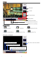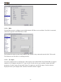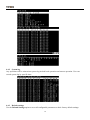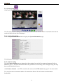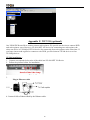
1
Network DVR on Chip
Your best choice for digital video recording and remote surveillance
VP-100
User Manual
Introduction
Installation
Graphic User Interface (GUI)
Configuration & Operation Via IR
Advance Network
Appendix
www.vpon21.com
Preface
Notice
The information in this manual was current when published. The manufacturer reserves the right to revise and improve its
products. All specifications are therefore subject to change without notice.
Note: Formosa21 will not be obligated to the responsibility outside the scope of VPON DVR.
Trademarks
VPON ® is a registered trademark of Formosa 21 Inc.
Microsoft, Windows, Internet Explorer ® are registered trademarks of Microsoft Corporation. Netscape, Navigator,
Communicator ® are registered trademarks of Netscape Corporation. Other brand and product names referred to in this manual
are trademarks or registered trademarks of their respective holders.
Trademarked names are used throughout this manual. Rather than place a symbol at each occurrence, trademarked names are
designated with initial capitalization. Inclusion or exclusion is not a judgment on the validity or legal status of the term.
Warning
To reduce risk of electric shock, do not remove cover. No user service-able parts inside. Refer servicing to qualified service
personnel.
Do not expose this appliance to rain or moisture.
Do not install this product in hazardous areas where highly combustible or explosive products are stored or used.
Severe impact or vibration may cause malfunction.
Do not move this product when VPON is working.
Position it in an open space with flat surface, and also maintain at least 15 cm between the left and right sides of the
body and the wall.
The lightning flash/arrowhead symbol, within and equilateral triangle, alerts the user to the presence of a shock hazard within
the product’s enclosure.
CE Warning
This is a Class A product, in a domestic environment this product may cause radio interference in which case the user
may be required to take adequate measures.
FCC Warning
This device complies with Part 15 of the FCC Rules. Operation is subject to the following two conditions (1) this
device may not cause harmful interference, and (2) this device must accept any interference received, including
interference that may cause undesired operation.
GUARANTEE
Every care has been taken in the preparation of this manual; if you detect any inaccuracies or omissions, please inform
FORMOSA21, INC. in Taiwan or your local distributor. FORMOSA21 cannot held responsible for any technical or
typographical errors and reserves the right to make changes to the products and manuals without your prior notice.
FORMOSA21 makes no warranty of any kind with regard to the material contained within this document, including, but not
limited, the implied warranties of merchantability and fitness for a particular purpose. FORMOSA21 shall not be liable nor
responsible for incidental or consequential damages in connection with the furnishing, performance or use of this material.
Important information
Before proceeding, please read and observe all instructions and warnings contained in this manual. Retain this manual with the
original bill of sale for future reference and, if necessary, warranty service.
When unpacking your VPON unit, check for missing or damaged items. If any item is missing, or if damage is evident, DO
NOT INSTALL OR OPERATE THIS PRODUCT. Contact your dealer or us for assistance.
Contents
1. Introduction
1.1 Main Features for VP-100---------------------------------------------------------------1
1.2 Product Specifications ---------------------------------------------------------------------------------------2
1.3 System requirements---------------------------------------------------------------------3
2. Getting Started
2.1 Summary of the installing---------------------------------------------------------------4
2.2 Installation-----------------------------------------------------------------------------------5
2.3 Power on------------------------------------------------------------------------------6
2.4 Configuration------------------------------------------------------------------------------6
3. The Local GUI
3.1 Introduction------------------------------------------------------------------------------8
3.2 Surveillance screen panel--------------------------------------------------------------8
3.3 Set up Video Quality--------------------------------------------------------------------9
3.4 I/O button--------------------------------------------------------------------------------10
3.5 POS button--------------------------------------------------------------------------------10
3.6 PTZ Control panel -----------------------------------------------------------------------10
3.7 Play button------------------------------------------------------------------------------11
1.play buttons ------------------------------------------------------------------------------------------------13
2. Split-screen display buttons-----------------------------------------------------------------------------13
3. Brightness/Contrast / Sharpness / Digital Zoom in playback---------------------------------------13
4. Status button ----------------------------------------------------------------------------------------------14
3.8 Bookmark----------------------------------------------------------------------------------14
3.9 Alarm log----------------------------------------------------------------------------------14
3.10 Backing up the data------------------------------------------------------------------------------------------15
3.11 Thumbnail Browse-------------------------------------------------------------------------------------------15
3.12 Search by Event----------------------------------------------------------------------------------------------16
3.13 Search by Text-----------------------------------------------------------------------------------------------19
3.14 Close playback screen--------------------------------------------------------------------------------------20
3.15 Setup-----------------------------------------------------------------------------------------------------------20
[System setup]
3.15.1 Password Protect------------------------------------------------------------------------21
3.15.2 Video------------------------------------------------------------------------------------21
3.15.3 Video input------------------------------------------------------------------------23
3.15.4 Disk--------------------------------------------------------------------------------24
3.15.5 TV out----------------------------------------------------------------------------24
3.15.6 OSD Text---------------- ------------------------------- -------------------------25
3.15.7 GPIO------------------------------------------------------------------------------25
3.15.8 TCP/IP------------------------------------------------------------------------26
3 . 1 5 . 9 A c c o u n t - - - - - - - - - - - - - - - - - - - - - - - - - - - - - - - - - - - - - - - - - - - - - - - - -- - - - - - - - - - - - - - - - - - - - - - - 2 6
3.15.10 Audio---------------------------------------------------------------------------------------27
3.15.11 Serial ports------------------------------------------------------------------------27
3.15.12 System info------------------------------------------------------------------------28
3.15.13 Date/Time------------------------------------------------------------------------28
3.15.14 ISP-------------------------------------------------------------------------------29
3.15.15 Registry------------------------------------------------------------------------------29
3.15.16 Running Mode------------------------------------------------------------------------30
3.15.17 Algorithm----------------------------------------------------------------------------30
3.15.18 NTP setup------------------------------------------------------------------------31
3.15.19 License-----------------------------------------------------------------------------31
3.15.20 Network neighbor------------------------------------------------------------------------32
3.15.21 System log-----------------------------------------------------------------------------33
3.15.22 Alarm log-----------------------------------------------------------------------------33
3.15.23 Configuration------------------------------------------------------------------------34
3.15.24 Default settings------------------------------------------------------------------------35
3.15.25 Revise firmware------------------------------------------------------------------------35
3.15.26 Reboot system ------------------------------------------------------------------------36
[Record setup]
3.16.1 DVR setup----------------------------------------------------------------------------36
3.16.2 Record schedule------------------------------------------------------------------------37
3.16.3 GPI Trigger----------------------------------------------------------------------------37
3.16.4 Pre-Alarm----------------------------------------------------------------------------38
[Alarm]
3.17.1 Alarm Setup--------------------------------------------------------------------------38
3.17.2 GPI Alarm----------------------------------------------------------------------------41
3.17.3 Motion Alarm ------------------------------------------------------------------------41
3.17.4 Video Lost----------------------------------------------------------------------------41
3.17.5 Disk Space Low------------------------------------------------------------------------42
3.17.6 Disk Error-----------------------------------------------------------------------------42
3.17.7 POS Event---------------------------------------------------------------------------43
[Motion Detection]
3.18 Motion Detection----------------------------------------------------------------------43
4. IR remote control operation
4.1 Introduction--------------------------------------------------------------------------------44
4.2 Main menu--------------------------------------------------------------------------------44
4.3 System setup------------------------------------------------------------------------------ 44
4.3.1 Password protect---------------------------------------------------------------------45
4.3.2
4.3.3
4.3.4
4.3.5
4.3.6
4.3.7
4.3.8
4.3.9
4.3.10
4.3.11
4.3.12
4.3.13
Video ( PTZ setup )-----------------------------------------------------------------46
Video input--------------------------------------------------------------------------48
Disks---------------------------------------------------------------------------------49
TV output--------------------------------------------------------------------------- 50
OSD text---------------------------------------------------------------------------- 50
TCP/IP----------------------------------------------------------------------------- 51
Account------------------------------------------------------------------------------52
Audio-------------------------------------------------------------------------------- 54
Serial ports----------------------------------------------------------------------------------------- 54
System information-------------------------------------------------------------------------------- 55
Date/Time----------------------------------------------------------------------------------------------55
Alarm---------------------------------------------------------------------------------------------------56
Mot ion Det ection----------------------------------------------------------------56
E-mail-----------------------------------------------------------------------------56
Video Popup--------------------------------------------------------------------- 57
Voice Call------------------------------------------------------------------------ 57
Set Action ( MD/Video lost/Disk space low/Disk error/Pos )----------------- 58
4.3. 14 ISP-------- ----------------------------------------------------------------------------------------- 59
4.3.15 Registry server----------------------------------------------------------------------59
4.3.16 Running mode------------------------------------------------------------------------60
4.3.17 Algorithm---------------------------------------------------------------------------- 60
4.3.18 NTP setup------------------------------------------------------------------------- 60
4.3.19 License setup------------------------------------------------------------------------- 61
4.4 Record Setup---------------------------------------------------------------------------- 61
4.4.1 DVR setup--------------------------------------------------------------------------62
4.4.2 Record schedule--------------------------------------------------------------------62
4.4.3 Motion detection-------------------------------------------------------------------63
4.4.4 GPI Trigger ------------------------------------------------------------------------64
4.4.5 Pre-Alarm--------------------------------------------------------------------------65
4.5 Playback----------------------------------------------------------------------------------65
4.5.1 Playback list-----------------------------------------------------------------------------65
4.5.2 Searching for a file----------------------------------------------------------------------67
4.5. 3 Locking files ----------------------------------------------------------------------------------68
4.5. 4 Backing up the data ----------------------------------------------------------------68
4.6 System Maintenance-----------------------------------------------------------------------69
4.6.1 Alarm log--------------------------------------------------------------------------69
4.6.2 System log------------------------------------------------------------------------70
4.6.3 Default settings-------------------------------------------------------------------70
4.6.4 Configuration file-------------------------------------------------------------------71
4.6.5 Revise firmware------------------------------------------------------------------71
4.7 System shutdown-----------------------------------------------------------------------71
5. VPON network operation
5.1 Introduction------------------------------------------------------------------------------72
5.2 Connecting-------------------------------------------------------------------------------72
5.3 Surveillance screen panel--------------------------------------------------------------73
5.4 Play button-------------------------------------------------------------------------------73
5.5 PTZ panel--------------------------------------------------------------------------------74
5.6 System Setup----------------------------------------------------------------------------75
5.6.1 System information----------------------------------------------------------------75
5.6.2 Camera setting----------------------------------------------------------------------75
5.6.3 Audio setting------------------------------------------------------------------------76
5.6.4 Set time and date-------------------------------------------------------------------76
5.6.5 Set NTP server--------------------------------------------------------------------- 77
5.6.6 System configuration--------------------------------------------------------------77
5.6.7 Set Serial ports---------------------------------------------------------------------77
5.6.8 Set pos--------------------------------------------------------------------------------78
5.6.9 Alarm and remote control---------------------------------------------------------------------78
5.6.10 Set names and on-screen display------------------------------------------------ 79
5.6.11 Set user authority------------------------------------------------------------------ 79
5.6.12 DVR setup-------------------------------------------------------------------------79
5.6.13 Record schedule------------------------------------------------------------------ 80
5.6.14 Motion Detection------------------------------------------------------------------ 80
5.6.15 GPI Trigger Recording------------------------------------------------------------------ 81
5.6.16 Set Pre-Alarm----------------------------------------------------------------------- 81
5.6.17 Playback-------------------------------------------------------------------------------81
5.6.18 Search--------------------------------------------------------------------------------82
5. 6.19 Send mail ----------------------------------------------------------------------------- 83
5.6.20 FTP upload------------------------------------------------------------------------83
5.6.21 Alar m log-------------- ----------------------------------------------------------84
5.6.22 System log------------------------------------------------------------------------84
5.6.23 Configuration file------------------------------------------------------------------------85
5.6.24 Back to home page----------------------------------------------------------------------85
5.6.25 View video without plug-ins----------------------------------------------------------------------85
6. Advance Network Setting
6.1 Connecting to the network-------------------------------------------------------------86
6.2 Configuring Static IP Address---------------------------------------------------------86
6.3 Configuring Dynamic IP Address-----------------------------------------------------86
6.4 Finding the IP address of the VPON on the register server----------------------------------------------87
6.5
6.6
6.7
6.8
Using xDSL or cable Internet----------------------------------------------------------87
Using PPPoE---------------------------------------------------------------------------87
Using dial-up Internet----------------------------------------------------------------------------------------88
Remote access using dial-up-----------------------------------------------------------88
Appendix
Appendix A: Recommend Motherboard--------------------------------------------------------------------------- I
Appendix B: Guide to Revise Firmware of VPON ------------------------------------------------------------- II
Appendix C: Remote camera control -----------------------------------------------------------------------------II
Appendix D: Voice Modem ---------------------------------------------------------------------------------------III
Appendix E : View video by PDA or Cell phone -------------------------------------------------------------- III
Appendix F : NET I/O (optional) -------------------------------------------------------------------------------- IV
Appendix G: Troubleshooting------------------------------------------------------------------------------------ VI
1.
Introduction
A VP-100 package includes one VP-40 video capture card and a DVR on chip DOM. VP-40 supports 4
camera input ports. After install them in a PC, it becomes a dedicated DVR system after power up. The
DVR System is a high performance digital video recorder with built-in mini web server and real-time
video capturing capability. The video is grabbed and compressed for faster transmission to your PC
through 10/100Mbps Ethernet. The video also can display through local VGA output . Besides, VP-100
supports digital recording function. It can record / playback / browse video simultaneously and save video
data by cyclic recording to PC hard disk.
VP-100 supports full motion live video and audio through Internet, Intranet connection. When supporting
more than 4 camera ports, extra VP-40 cards can be installed on the same PC of VP-100. A DVR on chip
DOM can support maximum 4 VP-40 capture cards. This makes the PC supporting up to 16 cameras.
After installing VP-100, the PC is ready as a DVR. When power up, it starts local DVR functions such as
monitoring through VGA output and recording to hard disk if it is configured to do that. For remote
monitoring or access to historical data, you will have to set up the LAN or Internet environments and
configure VP-100 IP information. When all these installation are done successfully, VP-100 delivers
real-time full-motion audio/video transmission to anywhere anytime. A PC with Internet browser and our
proprietary plug-ins software can do that. The camera can be remotely controlled to do zoom in and out,
and the unit can be triggered to initiate certain events. Configuration of VP-100 can be done by an IR
remote control unit or a mouse . A sample configuration is shown as below.
Figure1.1
VPON Network Configuration
1.1 Main Features for VP-100
Video & audio recording
Up to 8/12/16 camera inputs (color or B/W)
Up to 30 fps on each camera for local monitoring
Record / display / playback simultaneously
Built-in QUAD / Multiplexes functions for local monitoring
Local playback of recorded video on VGA or TV monitor
Remote playback from PC browser
Query recorded data by date, time & events
Control well-known brand PTZ Cameras
1
High video quality and low data rate
Up to 200:1 video compression
Multiple video compression engines: H.263, JPEG, M-JPEG, MPEG4
Network
Dynamic IP support for Internet access
Direct Dial-up available
Backup
Removable Hard Drives
Optional CD-RW / DVD+RW
Easy to use
Plug and play, non-Windows embedded real-time OS
Easy configuration via keyboard, IR Control, Home Page or RS-232 port
Standard web browser as the client application
Alarm function
Motion detection / Event trigger / Schedule / Pre-alarm recording
E-Mail & FTP alarm notification
Optional GPI/O for alarm control
FW1.3 New Features for VP-100
Point of sales DVR Integration
USB mouse support
SATA HDD support
Low-bandwidth support
FW1.4 New Features for VP-100
Alarm log
Import searching function for more user friendly
Weight recording
Water mark support
Modify POS License to three versions.
Selectable 30 days recorded files auto deletion function
Network Neighbor function support
Customization
Supports HTML file upload for home page customization
Supports FTP Server upload for customization
1.2 Product Specifications:
Model
Channels/Card
Display FPS/Card
Rec. FPS/Card (320X240)
Audio In/Card
Alarm In/Card
Compression Standard
Minimum System Requirement
VP-100*
4
120fps
120fps
1
4 in/4out (optional)
MPEG4 / JPEG / M-JPEG / H.263
Pentium IV 2.6GHz CPU or better
512MB DRAM
One IDE slot for DOM Chip
AGP VGA Card
Win 98 /2000/XP running MS Internet Explorer 6.0 or later
Browser Compatibility
Support TCP/IP , DHCP , NTP , HTTP , FTP
Communication Protocol
IDE or USB Interface HDD, CD-RW, DVD+RW
Backup Function
English , Traditional Chinese
Language
Note: Could use more powerful CPU to get the maximum frame rate.
2
1.3
System Requirements
Composite CCD camera, V8 or camcorder… (NTSC or PAL standard)
The equipment for connecting to network:
1.Network mode: RJ-45 Ethernet network port connected to Internet and a public IP address
2.Others: RS-232 Port and a serial cable for connecting to host PC.
3.A VGA or TV monitor for display.
PC for installing VP100
NOT EVERY PC PLATFORM CAN BE USED FOR VP100 INSTALLTION. PLEASE REFER TO MOTHER BOARD
SUPPORTING LIST IN APPENDIX.
PC for the configuration / browsing
1. Pentium 4 CPU or better, desktop PC or notebook
2. 256 MB RAM or above
3. AGP VGA Card
4. Microsoft Windows 95/98/2000/ME/XP or above
5. Internet Browser (such as Netscape Navigator 4.0 or Microsoft Internet Explorer 6.0 or above)
3
2.
Getting Started
2.1
Summary of the installing
Before install VP-100 to your PC platform, please make sure the PC’s Hardware is compatible with the
motherboards, which we have recommended in the appendix.
VP-100 contains:
Description
Quantity
VP-40 Capture Card
1
DVR on chip module (DOM)
1
IrDA Controller & receiver
1
Manual CD
1
Quick reference manual
1
Yellow IDE Cable
1
Watch dog Wire
1
Battery
2
Plug VP-40 onto the PC’s PCI slot. There is a flat cable comes with a DOM. Insert one end of the flat
cable into primary IDE slot. Then insert DOM to the slot at middle of the flat cable. There is also a power
cable comes with the DVR chip. Plug one end of the power cable to PC’s DC power plug and then insert
the small power plug into DVR chip. Please refer to fig 2.1 below for detail.
After complete the above installation, connect a VGA monitor to the VGA output of the PC. You will
need a LAN card on the PC for remote access. The VGA & LAN cards use on the PC shall both be
compatible to the supporting list, too.
Maximum of two hard disk units install on secondary IDE slot is recommended. You can install a third
hard disk at primary IDE slot as a slave unit. But this is NOT recommended. Please contact your local
reseller or Formosa21 customer service for more information.
c
To PC primary IDE slot
d
Connect to middle slot of IDE
To Motherboard
PCI slot
Composite video input from camera or
other video devices
Fig 2.1
e
To PC power supply
DC Power plug
Connect video signals to the camera input ports of VP-40. These signals can be Camera, VCR, TV or
VCD/DVD player as long as they are NTSC/PAL compatible composite videos.
4
2.2 Installation
Step 1 : Installing Motherboard
We recommend motherboards that support Linux device drivers. If you purchased a non-recommended
motherboard yourself make sure it works. We are not responsible for non-approved motherboards. We
carry recommended motherboards for system integrators to use. Put the motherboard together just like a
regular PC.
Step 2: Installing CPU
We recommend any Pentium 4 Class CPU. Install as usual and attach the heat sink and fan.
Step 3: Installing Memory
We recommend installing a good brand name 256MB DDR memory.
NOTE: If you choose MPEG4 compression standard, please install 512MB DDR memory.
DDR Memory
Step 4 : Installing VGA Card
We recommend VGA cards as in supporting list (Please check appendix) .We carry VGA cards for system
integrators. Insert the VGA card into the AGP slot. Not all VGA cards will work due to unsupported
Linux device drivers.
Step 5: Installing VP-40 Capture Card
Our capture card is proprietary and will only work with our DVR chip. Install the capture card into an
available PCI slot. Once the system boots the VPON firmware will automatically detect how many
capture cards are in the PCI slots.
VP-40 Capture card
Step 6: Installing the hard drives
For a single drive make sure the jumper settings is set on primary. Attach that with any ordinary IDE
cable onto the secondary IDE channel. For dual drives make sure one hard drive is set on primary and the
secondary on slave. Attach those to the IDE cable and plug into the secondary IDE channel. The max hard
5
drive size supported is 500GB each. For a total of 1TB.
Note: When VP-100 based DVR is working for the first time, the system will erase the data in the hard
disk. If there is important information in the hard disk, please remember to backup the data in another
storage before the hard disk is used in the VP-100 based DVR.
Step 7: Installing the VP-100 DVR module
The VP-100 DVR module sits on the primary IDE slot on the motherboard. If attaching a CD-RW to your
unit then put the VP-100 DVR module in the middle of the yellow IDE cable included. And then put the
end of the yellow IDE cable to the CD-RW and the other end to the primary IDE channel. The yellow
IDE cable must be used with the VP-100 DVR module and not any generic IDE cable. Then attach the
power connector from the VP-100 DVR module to a free lead from the power supply.
DVR module
Step 8 : Installing I/O Card (Optional)
GPI and GPO are use for alarm inputs and outputs control.
Note: I/O card is an optional device; if you need it please contact us.
I/O card (Model: VP-SI/O44)
Power Supply
We recommend using a 400W ATX power supply for the DVR unit.
2.3 Power On
After complete the installation , you can power on the PC as usual. Live videos should be displayed on
VGA screen if everything is OK.
2.4 Configuration
When you get videos display on VGA screen, you can configure the VP-100 PC DVR unit using mouse
or the IrDA controller comes with the VP-100 package. Please refer to User manual “Chapter 3
operating VPON by mouse , Chapter 4 Operating VPON by IrDA controller.
6
Change from GUI mode to IR mode
Default operation mode is GUI mode. VPON provides a GUI mode with mouse support. Be sure to plug
in a PS2 mouse at the back of the unit before or when it starts to boot. Go to the running mode in the
system settings. Change it from mouse mode to IR mode. The unit will reboot. Mouse mode is the only
mode where a log can be found.
7
3. Graphic User Interface (GUI)
3.1 Introduction
VP-100 can be configured using either the supplied remote control unit (or a keyboard) or a mouse. This
chapter covers mouse operation. The VP-100 must be in GUI mode for mouse operation. Under GUI
mode, keyboard is used ONLY for data entry.
Local surveillance GUI:
DVR basic information
Camera status
Playback
System configuration
Split-screen / Live surveillance
Full screen monitoring / I/O button
DVR basic information: including date, time, total hard disk size and LAN status.
Camera status:
R
Color
M
Recording Mode
Gray
No video signal
Blue
No recording
Red
Full recording
Color
Motion detection Status
Gray
Motion not detected
Yellow
Motion detected
G
Color Status of each DI and DO device.
Gray
DI or DO not detected
Red
DI or DO was detected
3.2 Surveillance screen panel
The Surveillance Screen Panel enables you to define which live images are displayed on screen.
A
B
C
8
A. Selectable 1 / 4 / 6 / 7 / 9 / 10 / 13 / 16 split-screen display
B. Use the sequence button to automatically cycle through all the connected cameras
C. The arrow buttons to get previous or next camera
Enlarge button
Click the enlarge button to switch to full screen live video display.
Double click mouse right button to switch back normal live video.
3.3 Setup Video Quality
Use the video quality button to set all the video parameters for the cameras connected to the VP-100.
1. First, please change to single screen as following .
Select camera
Video quality button / I/O button / POS button
Back to live surveillance / Enlarge video / System setup
2. Press the set quality button
, you can see the Brightness , Contrast , Saturation , Hue , Quality
(All) control panel.
Brightness- adjusts the amount of light or brightness for the selected camera according to your
preference.
Contrast - adjusts the difference between light and dark areas or contrast for the selected camera
according to your preference.
9
Saturation - adjusts the amount of color for the selected camera.
Hue - adjusts the dominant color for the selected camera.
Quality (All) - adjusts the video quality for all cameras. The default setting is 80. We recommend that
you do not set this to 100 to avoid slow video transmission rate and using up too much hard disk space.
3.4 I/O button
or
Click the “I/O” button to display the I/O panel.
When an alarm is triggered, the GPI and GPO that are connected will show the status of the input or
output device. Colors will change on the GPIO panel when the corresponding GPIO points are activated.
3.5 POS button
Click the “POS” button and the screen will show as below.
1. Firstly, please change to single screen as following .
2. After the “POS” button is pressed, the POS panel will appear at bottom of the screen.
3. POS transaction data with video will show on the screen and data ONLY on pos panel.
POS transaction data
3.6
PTZ Control
PTZ panel
After setting PTZ in the camera setup section, user can use the PTZ panel to control PTZ (Pan, Tilt, Zoom)
cameras. This panel is displayed when change to single screen.
10
PTZ panel
PTZ panel: You can do preset and recall, zoom in/out, focus, iris control to current camera.
Preset buttons- Save current camera position. You can save totally16 preset positions
Recall buttons- Move the camera to the selected preset position.
ZOOM buttons - adjust the zoom to provide a more closer or wider view of the subject.
FOCUS buttons - adjust the focus of the camera.
Speed buttons - Adjust the moving speed of the selected PTZ camera.
PTZ OSD menu / patrol / auto pan – Using OSD menu to control PTZ .The “
ok,”
” button is
” button is cancel.
Pan and tilt buttons - Adjust the pan and tilt of the selected camera include 45 degree
directional PTZ control at upper right, upper left, button right, button left of PTZ control panel
To set a camera configuration:
1. Select a camera using the numbered buttons (1~16) on the Surveillance Panel.
2. Adjust the Zoom, Focus, Speed, Pan and Tilt buttons until the camera is configured correctly.
3. Press a Set button to save the configuration.
The configuration you have saved can now be recalled with the corresponding Call button.
3.7 PLAY button
Click the PLAY button for playback the recorded files in the hard disk.
11
Watermark
Calendar
Function buttons
Play buttons
Split-screen buttons
Recording data status information
Lock file
Back to live surveillance
Function buttons:
1.
Bookmark
2.
4.
Thumbnail Browse
5.
Alarm log
Search by Event
3.
6.
Backing up the data
Search by Text
How to play recording file:
Step3: Select camera to playback.
Step1: Select a date from calendar.
Step2: Select an hour from time line.
Step4: Click anywhere on recording data score
bar to start playback from the required point.
12
Date Color
Red
Meaning
Have recording data
White
No recording data
Square
Today’s date
Orange
The day that was selected for playback
Lock file: click the score bar under time line can lock
file to keep the file not been erased by HDD cycle
back writing
Click to show normal recording status
Click to show motion detection recording status
Click to show alarm trigger recording status
Recording data status: click anywhere on score bar to start playback from the required point.
Select camera: enables you to select which camera images to display on screen.
1. Play buttons:
Use the Play buttons to control playback of stored footage from the cameras.
Step backward
Step forward
Play Pause
Control playback speed(1/8x ~ 4x)
The fastest speed of the single image playback is 4x; slowest speed is 1/8x. Click “+” button once to
double playback from normal. Click “-” button will decrease playback speed.
2. Split-screen display buttons:
Split-screen display buttons enables you to define which split-screen is displayed on screen.
Selectable 4 / 9 / 16 split-screen display.
The arrow buttons to cycle through all connected cameras.
3. Brightness/Contrast / Sharpness / Digital Zoom in playback – When pause playback, the brightness;
contrast or sharpness of the image can be adjusted. User can also zoom in specific point of the image to
get clear view.
Brightness Contrast Sharpness Smoothness Zoom-in Restore
13
4. Status Button
The status panel displays the playback status of the current recording. The aqua line (Data) indicates
record data over an one hour time interval. The yellow bars (Motion) indicate the instance when motion
was detected. The (GPI) indicate when a GPI event was detected. The moving orange line indicates
current playback status. Click anywhere on the Data, Motion, or GPI lines to start playback from that
point.
3.8
Bookmark
User can have bookmarks at the specific time during playback.
Bookmark:
1. During playing recording file user can click
“bookmark” button to mark the specific time
point.
2. User can write down the note and click “Add”
button to save it.
3. Select one of the lists of recording file in
bookmark field and click “play” button to
playback.
3.9
Alarm log
Any alarm will be written into alarm log including motion trigger、GPIO trigger、Disk error、Video loss
、POS event.…..etc. User can search alarm log by specific time and double click one of the alarm log on
the list to playback the video.
14
3.10
Backing up the data
If the DVR is equipped with CD/RW, DVD+RW drive, you can back up your recorded files to a CD,
DVD, or USB hard drive.
Note: The DVR will take some time to collect data before it can start back up process.
3.11
Thumbnail Browse
Finds video images and selects them for processing individually, in whole folders, using a simple time
selector and built-in image viewer .you can check out the results with the built-in viewer.
1. Select search starting time and camera.
2. Using a simple time selector and built-in image viewer .you can check out the results with the built-in
viewer.
15
Previous - Search forward
Next - Search backward
Zoom in - The whole Thumbnail search was divided to three layers. The first layer is hourly based. Each
picture on the windows is the first picture of that hour。When select a specific hour to do Zoom in, it goes
into second layer. The second layer displays 16 pictures based on evenly divided time slots in this hour。
Then if any one of these pictures is selected to do Zoom in,it goes into the third layer. This layer displays
16 pictures from left to right, that are most close to the time slot of layer two。
Zoom out - Back to one layer up。
Back- Back to Thumbnail Browser window
Ok - Start playback recorded file
3.12
Search by Event
Searches the list of recorded files for the specified event such as a specific area of motion or a GPI
Trigger that occurred within the specified time interval.
Search by GPI Trigger:
1. Rule Selection- choose one of GPI 1~16.
2. All Time Range- Select “All Time Range”、”Today”、”Yesterday” or “User Define” for quicker
searching.
3. Click “ok” to start search GPI Trigger files in the specific time.
16
4. Search results are as follow:
Previous search result / Next search result / Search result list / repeat
Search by Motion:
1. Selection Rule – Select from one of Motion 1~16. All Time Range- Select “All Time
Range”、”Today”、”Yesterday” or “User Define” for quicker searching.
2. Click “ok” to start search motion files in that specific time.
17
3. And then define search area .
4. Click “ok” to start searching motion files in that specific area.
5. Search results are as follow:
Previous search result / Next search result / Search result list / repeat
18
3.13
Search by Text
Searches recorded files that contain POS information of specified text.
1. After define POS text , select search starting time and camera .
2. Search results are as follow:
Previous search result / Next search result / Search result list / repeat / Enable or disable pos data
Note : Click the
“search result list” button to playback the pos data.
19
3.14
Close playback screen
Stop playback recording file and back to the recording file list menu.
[ System setup]
3.15 Setup
Click the Set Up button to show VP100 configuration set up the menu. There are three parts to the Set Up
menu - System Setup, Record Setup, Alarm and Motion Detection.
This section explains each of the menu pages in turn.
20
[System Setup]
3.15.1 Password Protect
The Password Protect screen helps you to enable password protection, set administrator and user
passwords, set the auto lock period and lock the system immediately. Enabling password protection
prevents unwanted users from accessing or configuring the VP-100.
Enter new passwords for Admin and User in the corresponding fields. Set an auto lock time if required in
the Auto lock after field. The auto lock function locks the system after a given time and a password is
required to unlock it. Click Lock Now! to lock the system immediately.
Note: If you do not have a keyboard connected to the system, you can use the on-screen keyboard to
enter your passwords. All the fields that can be edited using the on-screen keyboard are indicated
by the on-screen keyboard icon. Double-click the field to display the on-screen keyboard. Use
mouse to enter characters for the required field.
3.15.2 Video
The Video menu enables you to set video parameters such as the video standard and so on for each of the
connected cameras. Select the camera from the Camera drop-down box and fill in the details in each field
as required using mouse.
21
Standard: sets the video signal format. Choose NTSC in the US, or PAL in Europe and most Asian
countries. If you are not sure about this option, select Auto. VP- 100 will detect the video standard
automatically.
Brightness: adjusts the amount of light or brightness for the selected camera according to your
preference.
Contrast: adjusts the difference between light and dark areas or contrast for the selected camera
according to your preference.
Saturation: adjusts the amount of color for the selected camera.
Hue: adjusts the dominant color for the selected camera.
Quality: adjusts the video quality for each camera. The default setting is 80. We recommend that you do
not set this to 100 to avoid a slower rate of video transmission and using up a significant amount of hard
disk space.
Compression Boost: enables you to compress the video signal to save disk space and thus extend
recording time. It is recommended to keep this setting to None. The higher the compression boost, the
lower the video data rate. For a significantly lower data rate, we recommend you use the H.263 algorithm.
Auto Gain Control: enables automatic gain control to adjust the video signal strength.
22
Mirror Horizontal: flips the video signal from the selected camera along the horizontal axis.
Mirror Vertical: flips the video signal from the selected camera along the vertical axis.
Max Connection: limits the maximum number of connections allowed to access the VP- 100 over the
Internet. Set to zero to allow the maximum number of connections.
Max Bandwidth: sets the maximum bandwidth in bytes/second that can be used by users connecting to
the VP- 100 over the Internet.
Max Conn. Bandwidth: sets the maximum bandwidth allocated for each connection to the VP- 100. This
is the maximum bandwidth divided by the maximum connections.
Water Mark: Sets water mark on the video image.
Local Display: enables viewing the selected camera video signal on the local display. If this option is set
to Off, the camera is still optional and its video can be recorded if needed.
PTZ Device: Choice one PTZ from our support list. If user can’t find out PTZ camera, please contact us.
PTZ baud rate: each camera have different baud rate, please set correctly.
PTZ time out: The timeout value represents the time given to the cameras to respond to a command.
PTZ ID: each camera can define different ID, please set correctly when you have up to 2 PTZ cameras in
one system.
Dimension: sets 320 x 240 or 640 x 480 resolution for each camera.
Copy Camera Configuration To : User can select cameras and press “ok” button to copy the
configuration of current camera to the selected cameras.
3.15.3 Video input
To map physical camera inputs onto video window positions on the display screen. You don’t have to
map camera#1 to position#1 as in the example below. You can map camera#1 to any position from #1
to #12.
23
3.15.4 Disks
Use the Disks menu to configure network disks that the DVR uses to record data. If no disk is connected,
(No Device) appears in the Disk Device field.
Use keyboard or mouse to enter the IP address and Volume of any connected network disk. Click on the
Test button to test if the drive is working correctly.
3.15.5 TV output
Use the TV Output menu to configure the video output for the VPON DVR. The VPON DVR can support
standard VGA computer monitors or TV type screens. Set the device type, standard, outputs and other
parameters. Set the Camera (From) and Camera (To) options to specify the range of cameras that are
displayed in the cyclic display mode. Software based De-interlace support.
24
Use mouse to set each field. Ensure each field is set correctly before clicking OK. If parameters are set
incorrectly it could result in the display becoming unreadable and very difficult to correct.
3.15.6 OSD Text
Use the OSD Text menu to assign text for each of the connected cameras. For instance, you may like to
have text saying “c1” on the image from a camera installed in the c1.
To display the OSD text:
1. Select the desired camera from the Camera drop-down box.
2. Click the Enable field to display the text.
3. Adjust the position of the text display on the image using the X and Y parameters. A value of X=0 and
Y=0 would result in the text appearing at the top left corner of the camera image. Increasing the value
of Y moves the text down the screen. Increasing the value of X moves the test the right. Enter the text
to be displayed in the Text field.
4. Use the mouse to complete the fields and click OK to save changes.
3.15.7 GPIO
The GPIO (general purpose input output) menu enables you to view the status of the input and output
25
devices such as switches, sensors, LEDs, and so on and view their status. These devices can be attached
to the unit to turn external alarms (outputs) on or off when the specified input changes. When an alarm
has been triggered, the GPI and GPO that are connected will show the status of the input or output device.
GPI devices will show NC (normally closed) or NO (normally open) as the status of the switch.
Depending on the input, you can change the status of the GPO devices to On or Off as required.
Change the GPO status as needed. Make sure that the devices are working by checking the actual physical
status of the inputs and outputs after making changes in this menu.
3.15.8 TCP/IP
Use the TCP/IP menu to enter TCP/IP address details for the VP-100.
3.15.9 Account
Use the Account menu to set up an administrator name and password as well as the super user name and
passwords. You can also use this menu to set up to 256 additional users, their passwords and their
permissions on the system. Select the user number and assign a Name and password to it. Click the PTZ,
Playback, and Audio fields to enable access to these properties for the selected user. Select the cameras
that you want the user to have access to and set them to Yes.
26
Note: It is important that you set up the super user name and password. The super user is different
from the administrator and has access to only live videos and playback files. Use the More Users
field to change the authorities of Internet users.
3.15.10 Audio
Use the Audio menu to set parameters such as Mic Gain, Speaker, Mic Timeout and Speaker Timeout.
You can also perform a self test to test if the microphone and speaker are working correctly.
There are multiple audio inputs, user can define which audio mapping to which camera. “Audio1” is
audio input from motherboard. Other audio inputs are from video capture cards. Audio out is from
motherboard.
3.15.11 Serial ports
The RS232 serial ports (COM1 and COM2) are used to attach PTZ camera control cables, external
modems, cash register or GPIO modules to the VPON DVR. Use the Serial Port menu to set parameters
for the two serial ports.
27
3.15.12 System info
Use the System Info menu to display the system information such as disk parameters, TCP/IP properties,
firmware information, and so on, on the screen.
There are no configurable fields on this page. Click OK or Cancel to leave the screen.
3.15.13 Date/Time
Use the Date/Time menu to set the precise time and date on the system. You can also set the local time
zone in the T.Zone field.
28
3.15.14 ISP
If you are using dial-up access to the Internet, use the ISP menu to enter details of your Internet Service
Provider.
3.15.15 Registry
The Registry menu enables you to set up the registry server for your device. If you are using a dynamic IP
address for the VP-100, you can set up the device to post its IP address to the VPON registry server. You
can then look up your IP from the MAC address or server name.
29
3.15.16 Running mode
Use the Running Mode menu to switch between Network Mode and ISP Mode, and between Mouse
Mode and IR Remote Control Mode.
3.15.17 Algorithm
H.263: frame size is small and suitable for Network surveillance.
MPEG4: Video quality good and frame size small.
JPEG: Video quality best but frame size big.
30
3.15.18 NTP setup
Use the NTP Setup menu to enter details of the Network Time Protocol (NTP) server used to synchronize
the time of the device with the network.
After making the changes, click on the Test & Save button to verify that the server is operational. Click
OK to save changes.
3.15.19 License information:
1. There are two ways to grant POS license. One is key-in license key; the other one is plug-in a key-pro.
So if you plug-in a key-pro you don’t need to key in the license number again in the license setup
menu.
2. There are three POS License to three levels:
Level 1: Single POS unit – Can connect ONLY one cash register.
Single POS only one cash register. This level pos function doesn’t need to register.
Level 2. 4 POS units -- Can connect maximum 4 cash registers.
Level 3. Full functions – Can connect maximum 16 cash registers.
3. Click “system setup”
button to display the System Setup menus and select the License section.
31
Note: The license in the following is an example only. Each DVR should have different license
number. Please contact us for getting a license.
4. Key in your own license key.
Note: If you don’t have a keyboard connected to the system, you can use the on-screen keyboard to
enter your license key. Double-click the field to display the on-screen keyboard .Use the mouse to
enter characters for the required field.
5. Click the Register button when you see the “#POS” , it mean register successful.
6. Back to the live display. Click POS button to display the POS Panel. You can try to send out some
data from POS machine then POS text should show up with video.
3.15.20 Network Neighbor
User can copy the recorded files of VP-100 to other PC through network neighbor.
1. Enable the Network Neighbor function.
2. After define the server name, workgroup and WINS server, user can find out the DVR recording files
from Microsoft windows network neighbor.
Note: when you setup server name and workgroup, please key-in English characters or numbers
only.
32
3.15.21 System Log:
Any operation will be written into system log include local operation and remote operation. User can
search system log by specific time.
3.15.22 Alarm Log
Any alarm will be written into alarm log including motion trigger、GPIO trigger、Disk error、Video loss
、POS event.…..etc. User can search alarm log by specific time.
33
3.15.23 Export system configuration:
User can backup or restore system, record, alarm and motion detection setup data.
Backup configuration data:
1. Connect a USB flash to DVR for backup or restore configuration data. DVR will auto detect flash.
2. Select backup section and click a device, which is shown in the field.
3. Click “Backup” button to start to backup configuration data.
4. When user sees “vpcfg _ your DVR name _ Mac ID.bin” was saved in the field, it mean the backup
was done.
5. Click “ok” button to leave system setup menu.
Restore configuration data:
1. Select restore section and click a device, which is shown in the field.
2. Select one “*.bin” in the field
3. Click “Restore” button will pup-up a menu to ask you to over write data. Select “ok” to start to
restore configuration data.
4. When restore data action was done, system will ask you to reboot DVR. Press “ok” to reboot DVR.
5. After restart DVR, user will get the configuration setup data back.
34
3.15.24 Default settings
Use the Default Settings menu to reset all configurable parameters to their factory default settings.
Click Restore Defaults?(Yes/No) to restore defaults. Click Cancel or No to retain the current settings.
3.15.25 Revise firmware
Use the Revise Firmware menu to upgrade the VP-100 firmware.
35
Click Revise Firmware?(Yes/No) to start the firmware upgrade process. Click Cancel or No to abort the
attempt.
3.15.26 Reboot system
Use the Reboot System menu to reboot or shutdown the system.
Use the keyboard or mouse (recommended) to select either Shutdown or Reboot. Click OK to perform the
operation. Click Cancel or No to abandon.
[ Record Setup]
3.16.1 DVR setup
Use the DVR menu under the Record Setup tab to set the Digital Video Recorder parameters.
36
Select either Auto Stop or Cyclic Recording. Auto Stop recording stops when disk space runs out.
Cyclic Recording continues to record until disk space runs out and then overwrites the oldest records.
Click OK to save changes.
3.16.2 Record schedule
Use the Record Schedule menu under the Record Setup tab to set up automatic recording schedules for
each camera and audio. You can set up to 16 record schedules that automatically record at given times and
days even frame rate just remember to close auto speed setting. Weighted recording is for setting special
recording frame rate when event triggers.
3.16.3 GPI Trigger
Use the GPI Trigger menu under the Record Setup tab to enable recording video from specified cameras
when triggered by an external alarm(GPI) connected to the system. For instance, you may want to record
video from a camera installed at your front door when the door lock is opened. In this case, connected an
alarm module (not provided ) to lock and set the front door camera to start recording.
37
3.16.4 Pre-alarm recording
Use the pre-alarm menu under the record setup tab to determine how many frames are record before an
alarm event occurs. Each camera can be set separately and you can record up to 300 frames.
[ Alarm]
3.17.1 Alarm setup
Use the Alarm Setup menu under the Alarm tab to define what action is taken when an alarm is triggered.
Through this menu, you can set up an E-mail address to which an E-mail is sent when the alarm is
generated, or set up the device to display a video popup message on your monitor, or place a voice call.
38
The Voice Call options enable you to set up a voice modem that will make a call when the selected event
(such as a GPI alarm, or video lost from a camera) occurs. Set the following options:
Redial -sets the number of times the voice modem will redial
Voice Repeat -sets the number of times the voice message is repeated on the voice call
Rec. Time -sets the time for which audio is recorded
Modem Speaker -sets the internal or external speaker to be used
Voice File -selects the voice file to be sent
Edit File Name -enables you to change the file name of the voice file
Use the keyboard or mouse (recommended) to complete all fields and click OK to save changes. Refer to
the following sections to see how to select the voice call as the action for specific events such as GPI
alarm and so on.
Note: The Voice Call options will be grayed out in the menu system if the voice modem function is
not selected in the serial port setup menu. Make sure that a voice modem is enabled in device field
in the Serial Ports menu item in order to place voice calls.
Voice call features
A voice call message can be recorded using an internal or external microphone, and can be played
back using an internal or external speaker.
Up to 60 voice messages can be recorded and stored on the VP-100 and used for different alarm
events.
Messages recorded for the voice call function must be between 5 and 10 seconds.
Known issues with the voice call function
There will be three seconds silence between a voice call being answered and the start of the message.
If the voice call function calls a phone with an automatic answering machine, the VP-100 will
behave as if the phone has been answered.
The VP-100 does not support non-standard ringing tones. If the VP-100 calls a phone and an
unexpected tone is received, an error message will be generated.
39
POS event:
User can specify any keyword in the transaction data For Data Event Alerting. Such as VOID and NO
SALE
1. Click Setup button on the screen and select Alarm then enter Alarm setup function.
2. You can define events by numeric characters such as selling prices or abnormal text such as “VOID”
or “NO SALE”.
3. You can enter at most 20 POS events. Once the captured POS data contains one of the defined POS
events, VPON triggers actions for the event. For example, you can enter VOID and NO SALE in the
POS Event respectively.
4. Select the POS Event function and start to set up reaction when receiving the text data from POS
machine.
5. You can define how the VPON DVR reacts when receiving the text data from POS machine.
6.
7.
8.
9.
Beep- beeps when the event was occurred.
E-mail- sends e-mail to the specified address when the event was occurred.
Voice call- dial a voice call to the specified number when the event was occurred
Back to the live video after setting alarm. You can try to cancel a transaction from the POS machine
and VPON DVR should alerts.
Note: The text was captured from the POS machine; you should check what text will be sent from
the POS machine, then set appropriate text in POS Event.
40
3.17.2 GPI alarm
Use the GPI Alarm menu under the Alarm tab to set what actions are taken when a GPI alarm is generated.
You can set up the alarm through a message, a beep, a video popup, or E-mail.
3.17.3 Motion Alarm
Use the Motion Alarm menu under the Alarm tab to set what actions are taken when a motion detection
alarm is generated. You can set up the alarm through a message, a beep, a video popup, a voice call, or
E-mail.
Use the keyboard or mouse (recommended) to select the required GPI from the GPI drop-down box and
complete all fields. For each action, you can specify the time interval over which the GPI is monitored for
an alarm to be generated. For the Voice Call option, specify two telephone numbers where the call may be
placed along with the voice file. For the E-mail option, specify the recipient, subject, and text of the
E-mail along with which of the cameras.” status” is sent in the E-mail and the start and stop times. Click
OK to save changes.
3.17.4 Video lost
Use the Video Lost menu under the Alarm tab to set what actions are taken when video signal from a
camera is not available. You can set up the alarm through a message, a beep, a video popup, a voice call,
or E-mail.
41
Use the keyboard or mouse (recommended) to select the required camera for video lost from the Camera
drop-down box and complete all fields as described in GPI alarm. Click OK to save changes.
3.17.5 Disk space low
Use the Disk Space Low menu under the Alarm tab to set what actions are taken when the disk space is
insufficient to record data. This alarm is generated only when the DVR mode is set to Auto Stop. You can
set up the alarm through a message, beep, voice call, video popup, or E-mail.
Use the keyboard or mouse (recommended) to complete all fields as described in GPI alarm. Click OK to
save changes.
3.17.6 Disk error
Use the Disk Error menu under the Alarm tab to set what actions are taken when there is an error while
accessing the disk. You can set up the alarm through a message, a beep, a video popup, or E-mail.
42
Use the keyboard or mouse (recommended) to complete all fields as described in GPI alarm. Click OK to
save changes.
3.17.7 POS event
Select the POS event function and start to sep up reaction when receiving the text data from POS machine.
You can set up the alarm through a beep, a voice call, or E-mail.
3.18 Motion Detection
Use the Motion Detection page to set motion detection parameters for each camera.
43
1
2
3
4
Motion Detection Setup Procedure
1. Camera: Select the camera for setting motion detection.
2. Enable (Yes/No): Turn On/Off the motion detection.
3. Sensitivity: Select motion sensitivity level .
4. Directly drag the square on the screen to a desired & location for Motion Detection.
Each small square on the displayed grid can be set to detect motion. Use the left mouse button to make a
square sensitive to motion. Use the right mouse button to make it insensitive. Click OK to save changes.
44
4. IR Remote Control Operation
4.1 Introduction
This chapter covers remote control operation using IR remote controller. The VP-100 must be in IR
remote control running mode for this operation.
4.2 Main menu
Press the Menu button on the remote control to display the main menu on screen.
Menu button
Use the Up and Down arrow buttons to select one of the four options and press OK button to confirm
your choice.
4.3 System setup
The System Setup menu enables you to change many different parameters of the VP-100. This section
describes each option in the System Setup menu.
Use the Up and Down arrow buttons to highlight an option, and use the OK button to confirm your
44
choice. You can move between pages using the Prev Page and Next Page buttons on the remote control.
Up and Down
arrow buttons
OK button
Prev Page
Next Page
4.3.1 Password protect
Use the Password Protect option to enable password protection, set administrator and user passwords,
set the auto lock period and lock the system immediately. Enabling password protection prevents
unwanted users from accessing or configuring the VP-100. The Password Protect menu has the
following choices:
Enable - enables password protection.
Admin Pass - sets the admin password.
User Pass - sets the user password.
Auto lock After - enables password protection after the specified time interval.
Lock Now! - enables password protection immediately.
To set the user or admin password:
1. Use the Up and Down arrow buttons on the remote control to highlight the Admin Pass option to set
the administrator password or the User Pass option to set the user password.
2.
Press the Right arrow button to display the password entry screen.
3.
Press the keypad button on the remote control to display the on-screen keyboard.
45
Keypad button
3.
Use the Arrow buttons on the remote control to choose a letter and use the OK button to confirm
you choice.
4.
When the new password has been entered correctly, press the keypad button on the remote control to
turn off the on-screen keyboard.
5.
Press the OK button to confirm the new password.
When user or admin passwords are set and enabled, you will be prompted for a password before going on
further functions. Use the on-screen keyboard to set user or admin passwords as described.
To set the password protects function:
1. Select the Enable option from the Password Protect menu.
2. Use the Left and Right arrow buttons to toggle between Yes and No.
3. Press the OK button to confirm your choice.
The autolock function in the Password Protect menu will lock the system after the specified period of
inactivity.
To set the period of inactivity before the system is locked:
1. Highlight the autolock option in the Password Protect menu.
2. Use the Left and Right arrow buttons to increase or decrease the period of inactivity.
3. Press the OK button to confirm your choice.
To lock the system immediately:
1. Highlight the Lock Now! Function in the Password Protect menu.
2. Use the Left or Right arrow buttons to confirm the operation.
4.3.2
Video
Use the Video menu to set all the video parameters for the cameras connected to the VP-100. There is one
video screen for each camera with the following parameters:
Standard - sets the video signal format. Choose NTSC in the US, or PAL in Europe and most Asian
countries. If you are not sure about this option, select Auto. VP-100 will detect the video standard
automatically.
46
Brightness- adjusts the amount of light or brightness for the selected camera according to your
preference.
Contrast - adjusts the difference between light and dark areas or contrast for the selected camera
according to your preference.
Saturation - adjusts the amount of color for the selected camera.
Hue - adjusts the dominant color for the selected camera.
Quality (All) - adjusts the video quality for all cameras. The default setting is 80. We recommend that
you do not set this value to 100 to avoid slow video transmission and using up hard disk space
easily.
Compression Boost- enable you to compress the video signal to save disk space and thus extend
recording time. It is recommended to keep this setting to None. The higher the compression boost, the
lower the video data rate. We recommend you use the H.263 or MPEG4 algorithm for low data
rate applications..
Auto Gain Control-enables automatic gain control to adjust the video signal strength.
Mirror Horizontal – flips the video signal from the selected camera along the horizontal axis.
Mirror Vertical – flips the video signal from the selected camera along the vertical axis.
Max Connection - limits the maximum number of connections allowed to access the VP-100 over the
Internet. Set to zero to allow the maximum number of connections.
Max Bandwidth - sets the maximum bandwidth in bytes/second that can be used by users connecting to
the VP-100 over the Internet.
Max Conn. Bandwidth - sets the maximum bandwidth allocated for each connection to the VP-100. This
is the maximum bandwidth divided by the maximum connections.
Dimension- sets 320x240 or 640x480 resolution for each camera.
Water Mark-Sets water mark on the video image.
Local Display- enables viewing the selected camera video signal on the local display. If this option is set
to Off, the camera is still optional and its video can be recorded if needed.
PTZ Device- Chose one PTZ from our support list. If user can’t find out PTZ camera, please contact us.
47
To change the video parameters:
1. Use the Up and Down arrow buttons on the remote control to highlight the option.
2. Use the Left and Right arrow buttons to change the value assigned to the setting.
3. Press the OK button to confirm the new settings.
Each camera has its own video screen. To move between the screens for each camera, use the Prev Page
and Next Page buttons on the remote control.
PTZ Control
Select the type of PTZ cameras used and set each camera that has one connected to Yes. The timeout
value represents the time given to the cameras to respond to a command. Don’t forget to setup PTZ ID.
To set the timeout value for PTZ cameras connected to the VP-100:
1. Use the Up and Down arrow buttons to highlight the Timeout field.
2. Use the Right arrow key to increase the value and the Left arrow key to decrease the value.
3. Press the OK button to confirm the new value.
You can set and recall up to 6 preset configurations for each camera using the following buttons in the
PTZ control section:
Preset - save the current pan, tilt, zoom, and focus settings in one of 6 preset configurations.
Recall - recall the selected preset configuration.
ZOOM - adjust the zoom to provide a more closer or wider view of the subject.
FOCUS - adjust the focus of the camera.
Speed - Adjust the speed of the selected PTZ camera.
Pan and tilt - Adjust the pan and tilt of the selected camera.
4.3.3 Video input
This function is to map physical camera video inputs on VP-100 cards to the video positions
on local display. Normally, video input#1 is map to position #1. But you actually can set video
inputs to any position from #1 - #16, (depends on how many VP-100 cards you install) on the
screen as long as there is vacancy.
48
4.3.4 Disks
Use the Disks menu to add and remove network disks from the system. Network disks can be used to
provide more storage space for long time recording .
To add a network disk:
1. Highlight the disk you want to add and press the OK button.
2. When the Add Disk screen is displayed, press the OK button.
The Add Network Disk menu is displayed, enabling you to set the IP address and volume size of the disk,
test its validity, and save the disk parameters.
To enter an IP address:
1. Use the Up and Down arrow buttons on the remote control to highlight the IP/Addr option and
press the Right arrow button to confirm the choice.
2. Enter an IP address using the number buttons on the remote control.
Note: You cannot enter a period (dot) between the fields in the IP address using the remote control
keypad. Use the on-screen keypad to enter the dots.
3. Press the OK button to confirm the new address.
To enter a volume name for the new disk:
1. Use the Up and Down arrow buttons on the remote control to highlight the Volume option and press
the Right arrow button to confirm the choice.
2. Use the on-screen keyboard to enter a volume label for the new disk.
To test a network disk:
1. Use the Up and Down arrow buttons on the remote control to highlight the Test! option.
2. Press the OK button to confirm the choice.
49
The test result will appear on the screen.
To save disk parameters:
1. Use the Up and Down arrow buttons on the remote control to highlight the Save! option.
2. Press the OK button to confirm the choice.
4.3.5
TV output
The VP-100 can be connected to a VGA monitor or a TV to view the camera video signal. Use the TV
Output menu to set the following parameters for the video output port:
Device - sets the output to VGA or TV.
Standard - sets the signal format for the output device. Select from NTSC, PAL, SECAM, and so on.
Output to - sets the video output to the composite or S-Video signal.
Delay - sets the delay between consecutive camera signals when displaying all the camera signals
automatically.
Camera (From) - specifies the first camera signal displayed in the automatic cyclic camera mode.
Camera (To) - specifies the last camera signal displayed in the automatic cyclic camera mode.
Screen Split - sets the number (1, 4, 9, or 16) of cameras to be shown on the local screen.
Time Stamp - Enables and specifies the position of the time stamp on the screen.
Time Format - Specifies the format of the time stamp.
Deinterlace - Software –> based De-interlace support.
Use the Up and Down arrow buttons on the remote control to select any one of the displayed parameters
and use the Left and Right buttons to cycle through the available options. Press the OK button when
parameters are set correctly.
4.3.6 OSD text
A line of text can be displayed with the video from each camera connected to the VP-100. Use the OSD
Text menu to enable the text and alter it. You can also set the position of the text using the X and Y
parameter values. Increasing the value of Y moves the text down the screen. Increasing the value of X
moves the text to the right.
50
To alter the text position:
1. Use the Up and Down arrow buttons on the remote control to highlight X or Y.
2. Use the Right button to increase the value and the Left button to decrease the value.
3. Press the OK button when the value is correct.
Use the on-screen keyboard to alter the OSD text as follows:
1.
2.
3.
Use the Up and Down arrow buttons on the remote control to highlight the Text option.
Use the Right arrow button to confirm.
Press the keypad button on the remote control to display the on-screen keyboard.
Keypad button
4. Use the Arrow buttons to highlight the letters you need for your text and press the OK button to
choose them.
5.
6.
When your text is complete, press the Keypad button to remove the on-screen keyboard.
Press the OK button to save the new text.
4.3.7 TCP/IP
Use the TCP/IP menu to set the IP address of the VP-100, the gateway, the subnet mask, the DNS server
IP address, and the HTTP port. If you want to use the VP-100 on your network, see your network
administrator to obtain a valid IP address for the VP-100.
Network Neighbor function: User can see VP-100 recording directory from other PC through Microsoft
Windows network neighbor. Then user can copy files in that directory to PC or do
remote back up automatically, if user has the proper software installed on the PC.
Note: when you setup server name and workgroup, please key-in English characters or numbers
only.
To change the TCP/IP parameters:
1. Select the field to change using the Up and Down arrow buttons.
51
2.
3.
Press the Right arrow button to confirm.
Use the number pad on the remote control to enter a new value
4.
Press the OK button to confirm the new value.
Network Neighbor function:
After define the server name, workgroup and WINS server, user can find out the DVR recording files
from Microsoft windows network neighbor. See as following picture.
4.3.8
Account
Use the Account menu to set up an administrator name and password as well as user name and passwords.
The default administrator name is Webmonitor and the default password is OYO. You can also use this
menu to set up to 16 additional users, their passwords and their permissions on the system.
Note: It is important that you set up a user name and password. The user is different from the
administrator and has access to only the video. Use the More Users function to alter the authorities of
users who access the VP-100 from the Internet.
To set an Admin/User name or password:
1. Use the Up and Down arrow buttons to select the field to change.
52
2.
3.
4.
5.
6.
Press the Right arrow button to confirm.
Press the Key Pad button on the remote control to display the on-screen keyboard.
Use the Arrow buttons to select the letters you require and the OK button to confirm.
When the field is correct, press the Key Pad button to turn off the on-screen keyboard.
Press the OK button to confirm.
To set up additional users and their permission rights:
1. Use the Up and Down arrow buttons to select the More Users choice.
2.
3.
Press the Right arrow button to confirm.
Use the Arrow buttons to select the Name and Pass options and modify these fields in the same
manner as in the previous procedure.
4.
5.
6.
6.
7.
8.
Use the Up and Down buttons to select any cameras from Camera1 through Camera16.
Press the Right arrow to select Yes to allow the user to access and control the selected camera.
Use the Up and Down buttons to select the PTZ option.
Press the Right arrow button to select Yes to enable PTZ control of the selected cameras for the user.
Use the Up and Down buttons to select the Playback option.
Press the Right arrow button to select Yes to enable the user to record and play back the signal from
the selected cameras.
9. Use the Up and Down buttons to select the Audio option.
Note: Audio can be disabled for live viewing and playback of recordings using the Audio Disable
function.
11.
Press the Right arrow button to select Yes to enable the user to hear the live audio from the selected
cameras.
53
4.3.9
Audio
Use the Audio menu to set up the audio parameters for the VP-100. The configurable parameters areas
follow:
• Mic Gain – adjusts the gain of the microphone.
• Speaker – adjusts the speaker output level (volume).
• Mic Timeout – sets the timeout for the microphone.
• Speaker Timeout – sets the timeout for the speakers.
• Self Test (Mic -> Spk) – performs a self-test to ensure correct operation of the microphone and speaker.
• Camera - setup which camera mapping to which audio channels. Audio1 is the audio input from
motherboard. The other audio inputs are from video capture card.
Note: Make sure that audio is enabled when recording signals from the cameras attached to the VP-100.
To set the audio parameters:
1. Use the Up and Down arrow buttons to select a field to change.
2. Use the Right arrow button to increase the value and the Left arrow button to decrease the value.
3. Press the OK button to confirm.
4. Use the Up and Down arrow buttons to select the Self Test (Mic -> Spk) option.
5. Press the Right arrow button to set the option to on to make sure that the microphone and speaker is
working correctly.
4.3.10 Serial ports
The VP-100 can be connected to other serial devices such as external modems, GPIO (General Purpose
Inputs and Outputs), Voice Call devices, PTZ cameras, camera control devices, text input devices, or USB
serial ports, using two serial ports - COM1 and COM2. The RS232 standard is used for these ports. Use
the Serial Ports menu to set the following parameters:
54
COM1 Device - selects the type the serial device. You can select external modems, GPIO, voice call
modems, etc.
COM1 Speed - sets the speed (1200 to 115200 bps) for the serial device.
COM1 Flow Control - enables or disables the flow control for the device.
COM1 Data Bits - Sets the number of data bits (6, 7, or 8) for the device.
COM1 Parity - Sets odd or even parity.
COM1 Stop Bits - Sets 1 or 2 stop bits for the device.
To change the serial port parameters:
1. Use the Up and Down buttons to select the field to change.
2. Use the Left and Right arrow buttons to cycle through the available options for that field.
3. Press the OK button when the field is set correctly.
Note:
1. You can use the Prev Page and Next Page buttons on the remote control to toggle between the COM1
menu and COM2 menu.
2. When an optional GPIO module is connected to the serial port, the VP-100 detects it automatically and
provides GPIO options in the system menu.
4.3.11
System information
Use the System Information option to display the System Information screen and view information
about the boot disk, TCP/IP parameters, the MAC ID of the device, firmware version and date of
installation, model number, and hard disk properties.
4.3.12 Date/Time
Use the Date/Time option to set the year, month, day, hour, minute, second, and time zone in which the
VP-100 is installed.
To set the time or time zone:
1. Use the Up and Down arrow buttons to select the field to change.
55
2. Use the Left arrow to decrease the value and the Right arrow to increase the value for that field.
3. Press the OK button when the values are set correctly.
Note: The VPON VP-100 reboots to save the changes, if you modify the time zone.
4.3.13
Alarm
Use the Alarm menu to define what constitutes an alarm condition and how the VP-100 reacts when such
a condition occurs. You can configure an alarm condition to be generated when motion is detected by the
camera, if the video signal is lost from a camera, if the disk space is too low, if there is a disk error or if
pos event. Once the alarm is generated, you can set the alarm notification through a beep, a message, a
video popup, voice call, or E-mail.
The Alarm menu has the following submenus:
E-Mail - enables you to set up an E-mail address and verify it is working correctly.
Video Popup (sec) - sets the time for which a camera is displayed on your monitor when an alarm is
generated.
Voice Call - enables you to set conditions that generate a voice call when an alarm is triggered.
Set Action - sets the action that will generate an alarm condition for each camera.
Note: The Voice Call option will only be displayed in the menu if the voice modem function is selected
from the serial port menu.
To enter E-mail details:
1. Select the E-Mail option from the Alarm menu.
2. Press the Right button to confirm. The E-Mail submenu is displayed.
56
3. In the E-Mail menu, use the Up and Down buttons to select a field from the following:
Addr - Type the name of your mail server. See your network administrator for details about the address of
your mail server.
Name - Type your user name.
Pass - Type your password.
Sender - Type the e-mail address of the sender.
Test - Checks the validity of the provided E-mail address by sending E-mail.
5. Press the Right arrow button to confirm your selection.
6. Press the Key Pad button on the remote control to display the on-screen keyboard.
7. Use the Arrow keys to select the letters you need to complete the field and press the OK button to
confirm.
8. When the field is complete, press the Key Pad button to turn off the on-screen keyboard.
9. Press the OK button to save your changes.
Video Popup
Use the Video Popup menu to set up the time period for which the video from the selected camera is
displayed on your screen. The default screen is 20 seconds.
To set the video popup time:
1. Use the Up and Down arrow buttons to select the Video Popup option from the Alarm menu.
2. Use the Left arrow button to decrease the popup time and the Right arrow button to increase the
time
3. Press the OK button to save your settings.
The Voice Call options enable you to set up a voice modem that will make a call when the selected event
(such as a GPI or motion alarm, or video lost from a camera) occurs.
You must install a voice/fax modem on one of VP-100 COM ports, configure the COM port as a voice
Call/device, and make its protocol the same as that of the voice/fax modem for the voice call function to
work.
Voice call features:
A voice call message can be recorded using an internal or external microphone, and can be played
back using an internal or external speaker.
Up to 60 voice messages can be recorded and stored on the VP-100 and used for different alarm
events.
Messages recorded for the voice call function must be between 5 and 10 seconds.
To set the Voice call function:
1. Use the Up and Down arrow buttons to select the Voice Call option from the Alarm menu.
2. Use the Up and Down arrow buttons to highlight the Redial option.
3. Use the Left and Right arrow buttons to set the number of Redial attempts (0-9).
57
4.
5.
6.
7.
8.
9.
10.
11.
12.
13.
14.
15.
Use the Up and Down arrow buttons to highlight the Voice Repeat option.
Use the Left and Right arrow buttons to set the number of times the message is repeated (0-9)
Use the Up and Down arrow buttons to highlight the Time for Rec. option.
Use the Left and Right arrow buttons to set the duration of the recording (5-10 seconds)
Use the Up and Down arrow buttons to highlight the Modem Speaker option.
Use the Left and Right arrow buttons to select either Internal or External speaker.
Use the Up and Down arrow buttons to highlight the Voice File option.
Use the Left and Right arrow buttons to select a voice file to use.
Use the Up and Down arrow buttons to highlight the Rename option.
Press the OK button to rename the current file to the file named in the Voice File field.
Use the Up and Down arrow buttons to highlight the Record option.
Press the OK button to make a recording.
Known issues with the voice call function
There will be three seconds silence between a voice call being answered and the start of the message.
If the voice call function calls a phone with an automatic answering machine, the VP-100 will
behave as if the call has been answered.
The VP-100 does not support non-standard ringing tones. If the VP-100 calls a phone and an
unexpected tone is received, an error message will be generated.
Set Action
Use the Set Action option to define what action is taken by the VP-100 when an event occurs. The
following options are available:
Video Lost - generates an alarm when the video from the selected camera is not available.
Disk Space Low - generates an alarm when the disk space is insufficient.
Disk Error - generates an alarm if there is an error while accessing the disk.
POS Event - generates an alarm if there is an error while integrate pos data with video.
To configure events using the Set Action option:
1. Use the Up and Down arrow buttons to select an event from the list.
2. Press the Right arrow button to display the submenu for the event with the following options:
Message - displays a message on screen when the event occurs.
Beep - sounds a beep when the event occurs.
E-Mail - sends an E-mail to the specified address when the event occurs.
Voice Call - sends a voice call to a specified number when an event occurs.
58
Video Popup - displays the video from the selected camera on your screen.
3. Use the Up and Down buttons to select the desired action from the following options:
4. Press the Right arrow button for the required action to view the submenu.
5. After enabling the action, set up the Start and End Hour, Minute, and Second to make the feature
active during the specified time interval of the day. The default settings have the feature enabled
throughout the whole day.
6.
If you selected the E-Mail option as the desired action, you have to set up the recipient of the E-mail,
the subject and the text matter of the E-mail. You can specify which of the 16 cameras status is in the
E-mail.
4.3.14 ISP
If you are connecting to the Internet using dial-up, enter your ISP details using the ISP option from the
System Setup menu. Set up the following options:
Phone No. - enter the telephone number that is dialed by the dial-up modem.
Name - enter the user name of your dial-up account.
Pass - enter the password for your dial-up account.
TCP/IP - set up automatic or manual TCP/IP. If the VP-100 is connecting through a DHCP server, an IP
address is assigned to it automatically. If you want to set the IP address of the device manually, select the
Manual option.
To enter ISP details:
1.
Use the Up and Down arrow buttons to select a field to change.
2. Press the Right arrow button to confirm.
3. Press the Key Pad button on the remote control to display the on-screen keyboard.
4. Use the Arrow buttons to select letters and numbers from the on-screen keyboard and use the OK
button to confirm.
5.
6.
When the field is correct, press the Key Pad button to turn off the on-screen keyboard
Press the OK button to confirm the new field.
4.3.15
Registry server
The Registry Server menu enables you to set up the registry server for your device. If you are using a
dynamic IP address for the VP-100, you can set up the device to post its IP address to the VPON registry
server. You can then look up your IP from the MAC address or server name.
59
To enter Registry Server details:
1. Use the Up and Down arrow buttons to select a field to change.
2. Press the Right arrow button to confirm.
3. Press the Key Pad button on the remote control to display the on-screen keyboard.
4. Use the Arrow buttons to select letters and numbers from the on-screen keyboard and use the OK
button to confirm.
5.
6.
When the field is correct, press the Key Pad button to turn off the on-screen keyboard.
Press the OK button to confirm the new field.
4.3.16 Running mode
Use the Running Mode menu to switch between Network Mode and ISP Mode, and between Mouse
Mode and IR Remote Control Mode.
4.3.17
Algorithm
You can change the compression algorithm used by the VP-100 to record video. The VP-100 supports
MPEG, JPEG, MJPEG, and H.263 ,MPEG4 algorithms for compression. For the JPEG and MJPEG
algorithms, the video quality is better but the data rate is also high. The H.263 and MPEG4 algorithm
provides a good video quality with low data rate .
To set up the algorithm:
1. Use the Up and Down arrow buttons to select a field to change from the Algorithm menu.
2.
3.
Use the Right and Left arrow buttons to toggle the available options.
Press the OK button when the fields are set correctly.
4.3.18
NTP setup
Use the NTP (Network Time Protocol) Setup function to synchronize the real-time clock on the VP- 101
with the atomic clock. Before using this feature, make sure that the correct date, time and time zone have
been set up. Also make sure that the DNS IP number has been set up under the TCP/IP settings.
The following options are available in the submenu:
60
Enable - enables the NTP function to synchronize the real-time clock.
Period (Hour) - sets up the time interval after which the time is re-synchronized.
Server - selects the NTP server from several pre-defined choices.
Edit NTP Server - enables you to choose your own NTP server.
Test&Save? - tests the server and saves the changes.
To change NTP settings:
1. Use the Up and Down arrow buttons to select a field to change from the NTP menu.
2.
Press the Right button to confirm.
3.
4.
Press the Key Pad button on the remote control to display the on-screen keyboard.
Use the Arrow buttons to select letters from the on-screen keyboard and use the OK button to
confirm.
5.
When the field is set correctly, press the Key Pad button on the remote control to turn off the
on-screen keyboard.
6.
Press the OK button to save changes.
4.3.19 License Setup
There are two ways to grant POS license. One is key-in license key; the other one is plug-in a key-pro. So
if you plug-in a key-pro you don’t need to key in the license number again in the license setup menu. Use
the License menu to key in the license number.
There are three POS License to three levels:
Level 1: Single POS unit – Can connect ONLY one cash register.
Single POS only one cash register. This level pos function doesn’t need to register.
Level 2. 4 POS units -- Can connect maximum 4 cash registers.
Level 3. Full functions – Can connect maximum 16 cash registers.
4.4 Record setup
Use the Record Setup menu to set all the record options for the VP-100. There are four Record Setup
submenus - DVR, Record Schedule, Motion Detection, GPI Trigger and Pre-Alarm. This section
61
covers each submenu in turn.
4.4.1
DVR Setup
Use the DVR menu to set the DVR (Digital Video Recorder) mode. Choose Cyclic Recording to keep
recording on the hard disk continuously. Choose Auto Stop to stop recording when the disk is full.
You can set an alarm to be generated when the hard disk is full and send notification through a beep,
E-mail, or text message.
To change the DVR mode:
1. Select the Mode option from the DVR submenu using the Up and Down arrow buttons on the
remote control.
2.
3.
Use the Left and Right buttons to select either Cyclic Recording, or Auto Stop.
Press the OK button to save changes.
4.4.2
Record schedule
You can set up to 16 record schedules that automatically record at given times and days.
To configure a record schedule:
1. From the Record Schedule menu, pick a schedule to change from the displayed list, using the Up
and Down arrow buttons.
2.
Press the Right button to display the parameters for that schedule.
62
3. Use the Up and Down arrow buttons to select a field to change, from the following options:
Enable -enables the recording schedule.
Mon through Sun - enables recording on the specified days of week.
Start Hour/Minute/Second - sets the exact time when the recording starts.
Stop Hour/Minute/Second - sets the exact time when the recording ends.
Camera 1 through 16 - sets the recording mode for the selected camera. Select Normal Record to record
continuously. Select Motion Detect to record only when motion is detected. Select OFF to disable
recording.
Audio - enables recording of sound along with the video signal.
Frame Rate Setup - sets the frame rate for recording. Set Auto Speed to Yes and the device evenly
divides the recording frame rate amongst all cameras. If set to No, you can manually set up the individual
frame rates for each camera.
Weight recording- weight recording is setting special recording frame rate when an alarm of one of
camera was triggered.
4.
5.
6.
Use the Right and Left arrow buttons to change the value of that parameter.
Use the Prev Page and Next Page buttons to move to the previous or next page.
Press the OK button when all parameters are set.
4.4.3
Motion Detection
To set motion detection conditions:
1. Use the Up and Down arrow buttons to select the Motion Detection option from the Alarm menu and
press the OK button.
2. When the motion detection menu appears, uses the Up and Down Arrow buttons to select one of the
following options:
• Enable – configures the motion detection feature for each camera.
• Sensitivity – sets the sensitivity value for detecting motion.
• Set Detect Area – sets the area in the camera’s field of vision over which motion is detected. This
63
option is displayed only after you set the Enable option to Yes.
• Enable all area – sets the all area is motion detect area.
• Disable all area –set no area is motion detect area.
3. Select the Enable field and use the Left and Right arrow buttons to toggle between Yes, to enable the
motion detection feature, and No, to disable it.
4. Select the Sensitivity choice and use the Left/Right arrow buttons to decrease/increase the sensitivity.
We recommend that you keep the sensitivity level to its default setting. If the sensitivity level is
adequate, an orange square is displayed in the upper left-hand corner of the screen when motion is
detected.
5. Select the Set Detect Area option and press the Right arrow button to configure the area as follows:
i. The highlighted area in red is the area monitored by motion detection. Use the Arrow buttons to
move the cursor.
ii. Press the OK button to cut off any areas where you want to disable motion detection. If you want
motion detection enabled in the entire field of vision of the camera, leave the screen completely red.
iii. Press the Cancel button to return to the previous menu when done.
6. Select the Save option and press the OK button to save all your changes.
7. Use the Prev Page and Next Page buttons to move to the motion detection menus for all connected
cameras.
8. Press the OK button when settings are correct. You need to provide E-mail details if you want an
E-mail to be sent when an alarm occurs.
4.4.4 GPI Trigger
Use the GPI Trigger function to enable recording video from specified cameras when triggered by an
external alarm (GPI) connected to the system.
64
4.4.5 Pre- Alarm
Use the Pre-Alarm function to determine how many frames are recorded before an alarm event occurs.
Each camera can be set separately and you can record up to 300 frames.
To set the Pre-Alarm frame capture:
1. Use the Up and Down arrow buttons to select Pre-Alarm option from the Record Setup menu.
2. Press the OK button to display the Pre-Alarm menu.
3. Use the Up and Down arrow buttons to select the camera to change from the list.
4. Press the Right arrow button to confirm.
5. Use the number buttons on the remote control to enter a new value.
6. Press the OK button when the value is set correctly.
4.5 Playback
Use the Playback function to display a list of all recordings stored on the VP-100. Use the Up and Down
arrow buttons to select a recording to play back and press the OK button to confirm. The chosen track is
played. Use the Prev Page and Next Page buttons on the remote control to move
between pages.
4.5.1 Playback list
Use the Playback list function to display a list of all recordings stored on the VP-100 as follows.
1.
Use the Up and Down arrow buttons to select a recording to play back. The alarm condition which
65
caused the file to be recorded is indicated in the list. For instance, in the screen shot shown here, the letter
M next to a file indicates that the file was recorded after motion was detected by the camera. “A”
indicates that the file was recorded after a GPIO event. An asterisk (*) before the date indicates that the
file is locked.
2.
2.
Press the OK button to confirm. The chosen recording is played back.
Press the Display button on the remote control to display various properties of the recorded file. The
date and time of recording are displayed in the upper right corner.
Progress - A one hour time line is displayed at the bottom of the screen with the moving orange line
indicating the status of playback.
Recorded Data - The aqua colored portion is where there is recorded data in that hour . A full blue line
means that the whole hour interval was recorded.
GPI - The screen shows where alarm triggers were generated. The red bar shows the trigger. To move to
the next motion detection or alarm trigger event, press the Right/Left arrow buttons.
66
Motion Detection – The yellow bars represent where motion detection was set off.
Searching for a file:
The VP-100 playback list can be searched for a specific file. You can conduct the search based on time,
event, or text.
4.5.2 To search for a recorded file:
1. While viewing the play list, press the Menu button to display the menu.
2. Select one of the following options using the Up or Down arrow buttons:
Search by Time - searches the list of recorded files for the specified recording time.
Search by Event - searches the list of recorded files for the specified event such as a GPIO trigger that
67
occurred within the specified time interval.
Search by Text - searches the list of files recorded with POS information for specified text that was
recorded within the specified time interval.
3.
Press the Right arrow button to view the submenu for the selected option.
4. Select each of the options such as Year, Month, Day, and so on using the Up or Down arrows.
5. Modify the settings as required using the Left and Right arrow buttons.
Note: If you select the Search by Event option, choose an event from GPI 1~16. If you choose the
Select by Text option, enter the text using the Key Pad button.
6. Press OK when done to conduct the search.
4.5.3
Locking files
To prevent accidental deletion of recorded files, you can lock a file. This also prevents over-writing of the
file when the recording mode is set to Cyclic.
To lock a file:
1. While viewing the play list, use the Up/Down arrow buttons to select the desired file.
2.
Press the Menu button to display the menu.
3. Select the Lock File! option using the Up or Down arrow buttons:
4. Press the OK button to confirm.
The file is locked and cannot be deleted or over-written. There is an asterisk (*) ahead of the file name. To
unlock a file, follow the same procedure and select the Unlock File! option from the menu.
4.5.4
Backing up the data
If the system is equipped with CD/RW, DVD+RW drive, you can back up your recorded files to a CD,
DVD, or USB hard drive.
To back up your data:
1. While viewing the play list , press the Menu button to display the menu.
2. Select the Backup option using the Up or Down arrow buttons.
3. Press the OK button to confirm.
68
The VP-100 detects if there is a backup device connected to it and starts backing up data.
Note: The VP-100 will begin to collect data as soon as the above screens are displayed. When the
required data has been collected, the backup can begin.
4.6 System Maintenance
Press the Menu button on the remote control to display the main menu on screen. Use the Up and Down
arrow buttons to select one of the five options and press the OK button to confirm your choice.
4.6.1 Alarm log
Any alarm will be written into alarm log include video loss, disk error….etc. User can search alarm log
by specific time.
1. Press “ok” button on “alarm log” option
2. There are many ways to quickly reach alarm log information. Include search by time, directly list all
log, or only GPI, GPO or motion triggered log….
3. After selected one of the searching way, user can see the log and press “ok” button to enter submenu
to get more detail information of log.
69
4.6.2 System log
Any operation will be written into system log include local operation and remote operation. User can
search system log by specific time.
4.6.3 Default settings
Use the Default Settings option to reset all configurable parameters to their factory default settings.
70
When the Default Settings option is chosen from the System Setup menu, a message is displayed asking
you to confirm. Press the OK button to confirm, or the Cancel button to cancel the operation.
4.6.4 Configuration file
User can backup or restore system configuration values to or from a file. Use Up and Down arrow buttons
to select either Backup or Restore Configuration.
4.6.5
Revise firmware
Use the Revise Firmware option to upgrade the firmware in the VP-100. The firmware can be revised
through an external read-write CD drive, a USB flash drive, or a USB thumb drive. Connect the device to
the VP-100 and then use this option.
4.7 System Shutdown
Use the System Shutdown option to shut down or reboot the system. To shut down or reboot the system:
1. Use the Up and Down arrow buttons to select either Shutdown or Reboot.
2.
Press the OK button to confirm.
3. Press the OK button to confirm the operation again, or press the Cancel button to cancel the
operation.
71
5. VPON Network Operation
5.1 Introduction
VP-100 can also be configured over a network using a PC running a standard web browser. This
chapter covers network operation.
5.2 Connecting
The VP-100 GUI can be viewed from a standard internet browser when the device is connected on the
same network as your PC or if it is connected through a cable or xDSL modem to the Internet. Refer to
the hardware manual for more information about making connections using the RJ-45 Ethernet (LAN)
port. Make sure that the VP-100 is configured for Network running mode.
To access the VP-100 from remote browser:
1. Open a browser window on a terminal that has network access to the VP-100.
2. Type the IP address of the VP-100 in the browser address bar.
Default User Name: webmonitor
Default Password: oyo
The first time you attempt to view the VP-100 user interface using a web browser, an ActiveX installation
procedure will begin automatically. When the following window appears, click on the Download
LVSETUP.EXE link. The download will begin and the following window will appear.
Click Open to download and install the new plug-in. The download status is displayed and you are
prompted for an installation location.
Click OK to complete the installation. The following message will appear.
72
When installation is complete you will be able to view the VP-100 Home Page.
The ActiveX installation is necessary only at first time.
5.3 Surveillance screen panel
The Surveillance Screen Panel is very similar to the one on the local GUI. See Surveillance screen
panel on page 8.
Surveillance screen panel
There is no Sequence button on the network GUI. This feature is only available on the local GUI.
5.4 Play button
Click the Play button to display a list of all the available recordings stored on the VP-100 in a new
browser window.
73
Play button
Click List All to display the entire list.
From field
To field
Query button
List all button
Play file on this
time button
Click on a video recording to play it in a separate browser window. Play a recorded video from a specific
time and date by entering the time and date in the From field and clicking Play file on this time.
Search for files between particular times and dates by entering the dates in the To and From fields
and clicking Query.
5.5 PTZ panel
The network GUI PTZ panel is exactly the same as the local GUI PTZ panel. See PTZ panel on page 10.
74
5.6 System Setup
Click the SETUP button to display the setup screen.
Use the setup screen to change user definable parameters for the VP-100. Choose a submenu from the list
on the left and click the link to display it.
5.6.1 System information
Click the System Information link to display the System Information page.
No information on this page is changeable.
5.6.2 Camera setting
Use the Camera Setting page to change the video settings for each of the connected cameras. Refer to
Video on page 21 for more information about the parameters. Each setting can be changed using the drop
down menus and check boxes.
• Set Camera Control – sets PTZ control for the cameras. See PTZ control on page 21 for more details.
You can also enter a maximum number of connections allowed for each camera and maximum
bandwidths.
75
5.6.3 Audio setting
Use the Audio setting menu to set parameters such as Mic Gain, Speaker, Mic Timeout and Speaker
Timeout. You can also perform a self test to test if the microphone and speaker are working correctly.
There are multiple audio inputs, user can define which audio mapping to which camera. “Audio1” is
audio input from motherboard. Other audio inputs are from video capture cards. Audio out is from
motherboard.
5.6.4 Set time and date
Use the Set Time and Date page to set the time and date. Select a time zone from the drop down menu
and enter new local time and date using the keyboard. Click Done when all fields are updated. Click
Undo to revert to original settings. If you change the time zone, the system will reboot.
76
5.6.5 Set NTP server
Use the Set NTP Server page to set parameters for a NTP (Network Time Protocol) server to
synchronize the device time with the atomic clock.
Select a server and enable it using the drop down menus. Enter a time period using the keyboard to
indicate the period after which the time is resynchronized. Click Done when all parameters are entered
correctly. Click Undo to revert to original settings.
5.6.6 System configuration
Use the System Configuration page to set the following parameters for the VP-100.
• Running mode – sets the operation and control mode.
• TCP/IP setting – configures TCP/IP. Fill in the IP address and subnet mask settings.
• ISP setting – sets up dial-up parameters for sending E-mails.
• Account Setting – sets up the administrator and user, and their passwords.
• COM1/2 Port Setting – sets up the serial ports.
• Set IP Registry Host IP Address & Path – sets up the registry server.
5.6.7 Set serial ports
The RS232 serial ports (COM1 and COM2) are used to attach PTZ camera control cables, external
modems, or GPIO modules to the VP-100. Use the Serial Port menu to set parameters for the two serial
ports.
77
5.6.8 Set pos
Use the Set POS page to set the color and front size for each of the connected cameras. Use the serial
Ports menu to set the following parameters. Click the “Done” button to save the new settings.
5.6.9 Alarm and remote control
GPI devices will show NC (normally closed) or NO (normally open) as the status of the switch.
Depending on the input, you can change the status of the GPO devices on On or Off as required.
78
5.6.10 Set names and on-screen display
Use the Set Names and On-Screen Display page to set names for the server and all cameras. You can
also use this page to enter the text to be displayed on screen with each camera under the Set Overlay
Text option. Use the x and y fields to define the position of the displayed text. Use the Set Time Stamp
option to define the format of the time stamp and where it appears on the display for each camera.
5.6.11 Set user’s authority
Use the Set User’s Authority page to set the individual privileges of up to 256 users. Enter the user
number in the User field. Assign a name and password in the respective fields. To restrict users from
viewing particular cameras, select the required cameras from Camera 1~16. Enable Camera
Control, and Playback of the video recording as needed.
5.6.12 DVR setup
Use the DVR Setup page to set the recording mode to either Auto Stop (stops when disk space runs out)
or Cyclic Recording (overwrites oldest recordings when disk space runs out).
79
5.6.13 Record schedule
Use the Record Schedule page to set up to 16 automatic recording schedules. For each record schedule,
select the day, and start and stop times for recording. For each camera, select off, Normal Recording,
Motion Detection Recording , GPI Trigger Recording or MD&GPI Trigger Recording to record
only when motion is detected. Enable Audio if you want to record audio also. Weight recording is setting
special recording frame rate when an alarm of one of camera was triggered. Select a Frame Rate of
recording for each camera.
5.6.14 Motion detection
The Motion Detection page enables you to set the motion detection feature for each camera. You can
adjust the area in the camera’s field of vision that will checked for motion. Click on the grid to enable or
disable motion detection. The red rectangle in the upper left corner indicates that motion is being detected.
80
5.6.15 GPI Trigger Recording
Use the GPI Trigger Recording to set up to 8 automatic GPI recording schedules. Clink the “Enable”
item box to start the GPI Trigger, and then set the timetable for recording the Trigger. Click “Done”
button to save the new setting.
5.6.16 Set Pre-Alarm
The Set Pre-Alarm page on the network GUI enables you to set the number of frames that are recorded
from each camera before a trigger is generated. Up to 300 frames can be recorded.
5.6.17 Playback
The Playback page enables you play back a video recording of your choice. Specify the day and time in
81
the To and From fields and click the Play file on this time! field to play back files in the specified time
duration. Click List All to list all recorded files. Click Query to search for a particular file based on
Event or Text. Click a file to play it back.
The file plays back in the browser window with the status at the bottom. Specify the resolution in the
Dimension field. Select the camera whose video you want to watch in the Camera field and select the
number of cameras (1, 4, 9, or 16) in the Display field. Specify a high or low Bandwidth and click
Download&Save to save the video recording to your local disk. Select Data, Motion, or GPI to view the
status of the recorded file and the instances where the recording was triggered by motion detection or GPI.
Snapshot
Playback speed
Note: The playback start time can be changed to jump to any time during the recording. Click on
the playback start time and change the time using the keyboard.
5.6.18 Search
Search video clips based on text( POS transaction data).
1. Click search button and enter the submenu.
2. You can search by any key word base on POS transaction data (text).
3. If you want to find out data faster, we recommend you to narrow down searching day, time and
cameras to get faster response.
4. Press Query button when done to conduct the search.
82
5.6.19 Send Mail
The VP-100 can send a snapshot by E-mail when triggered by an alarm. Use the Send Mail page to set Email details for each camera.
Under the Individual Settings, specific the type of event that cause the E-mail to be sent in the Type field
by choosing Motion Detect or GPI. Fill in the start and stop time for monitoring the alarm, the recipients,
subject and content of the E-mail. Enable a snapshot of the camera video to be attached to the E-mail by
selecting cameras in the Snapshot option.
Under the Global Settings, fill in the mail server details. Fill in the details using mouse and keyboard and
click Done when complete.
Note: If you set a domain name in the mail server setting, provide the DNS IP address in the system
Configuration.
5.6.20 Ftp Upload
The VP-100 can upload snapshots from the camera using FTP to a predefined location in the event of an
alarm. Use the FTP Upload page to set FTP details.
83
Under the Individual Settings, specify the type of event that causes the E-mail to be sent in the Type
field by choosing Motion Detect or Continuous. Fill in the start and stop time for monitoring the alarm,
the file name and directory for FTP. Enable a snapshot of the camera of video to be uploaded by selecting
cameras in the Snapshot option.
5.6.21 Alarm log
Any alarm will be written into alarm log including motion trigger、GPIO trigger、Disk error、Video loss
、POS event.…..etc. User can search alarm log by specific time and double click one of the alarm log on
the list to play specification-recording data.
5.6.22 System log
Any operation will be written into system log include local operation and remote operation. User can
search system log by specific time.
84
5.6.23 Configuration file
User can backup or restore system configuration values to or from a file.
5.6.24 Back to home page
The Back To Home Page link will redirect you back to the VP-100 home page.
5.6.25 View video without plug-ins
You can view video even if the machine you are working on does not have the plug-ins necessary for
video monitoring. Click the View Video Without Plug-ins link to view the video page without plugins.
You will need to enter an administrator user name and password to view without plug-ins.
Note: Your browser must be configured to support Java applets to view without plug-ins.
85
6. Advance Network Setting
6.1 Connecting to the network
Note: To connect the VPON to an existing LAN, set up by using the supplied IrDA remote control first.
1.
2.
3.
4.
5.
Connect an Ethernet-capable computer to the VPON LAN port using an RJ-45 UTP cable or connect
both of the PC and VPON to a same hub.
The default IP address for the VPON is 192.168.10.10. Set your PC IP address to 192.168.10.xxx
(where xxx is a value between 0 ~ 254). Set the subnet mask to 255.255.255.0.
Reboot the PC.
Use IE Web browser version 60. SP2 up to access http://192.168.10.10. The login dialog box will
appear. If you have previously changed the administration login or password, enter the login name
and password you previously set. Otherwise, enter the default login name “webmonitor” and the
password “oyo” then click OK.
For first time accessing VPON, you will be prompted to install Live Video ActiveX. Download and
run the file to install ActiveX. Then restart IE browser, you will be able to see the videos. If you
choose not to install Active X, you can view videos from the VPON by clicking on the View Video
without Plugins link at the bottom of the page. At the prompt, enter the same administrator login
name and password as before. This uses a Java applet to display the video.
6.2 Configuring Static IP addresses
Static IP addresses can be public or private. Public IP addresses allow access to the VPON from the
Internet. Private IP addresses only allow users on the same LAN to access the VPON (regardless of
whether the LAN is connected to the Internet or not). Ask your network administrator to assign an
appropriate IP address.
6.3 Configuring Dynamic IP addresses
If your LAN or Internet connection uses DHCP, the VPON needs to be registered with a registry server.
Users wanting to view your VPON can access the registry server to find the IP address. By default, the
VPON is set to be registered at http://registry.nfic.com.tw. This is a server set up by Formosa21 for
VPON series users. If you wish to set up a different registry server, Formosa21 recommends using a
VP-300 video server, although other servers may be used. See your network administrator for instructions
on selecting a registry server.
The Registry Host Address, Registry HTTP Port and Registry Host Path in system Configuration under
“Advance Settings” are the set to the default settings of the Formosa21 registry server. The Registry Host
Address is the IP address or Fully Qualified Domain Name (FQDN) of the registry server.
The Registry Host Path is the file path on the registry server where the index exists. See your network
administrator for assignment of these values if you want to make changes.
86
6.4 Finding the IP address of the VPON on the registry server
1. To find the IP address of the VPON when using DHCP, you need to search the registry server which
the VPON is registered to. Use a computer connected to the internet and a standard browser. Enter
the FQDN of the registry server into the browser to access the server.
2. After accessing the registry server, search for your VPON by name or MAC ID (Ethernet address).
You can find your MAC ID by viewing the System Information page in the Web Administration page.
Alternatively you can browse through all registered VPON units on the registry server to find your
VPON.
3. Enter the IP address supplied by the registry server into your browser to access the VPON.
6.5 Using xDSL or cable Internet
You can connect the VPON to the Internet via xDSL or cable just as you would as normal computer.
Connect the modem (router) according to the documentation.
If a static public IP address is assigned to your xDSL or cable internet account, you must assign this to
the VPON.
If you are using ADSL or cable Internet and your modem (router) supports DHCP, set the VPON IP
address to 255.255. 255.253. This requests the modem to assign an IP address.
You must register with a registry server to use dynamic addresses under DHCP. Follow the directions in
Configuring Dynamic IP addresses on page 86 to register with a registry server.
6.6 Using PPPoE
If your xDSL or cable router uses PPPoE, an IP-sharing router is required, as the VPON does not support
PPPoE. Regardless of whether you use a static IP address or a dynamic IP address, you will need to set
the DHCP server IP address and IP forwarding but if you use a static IP address you do not need to
register with a registry server.
1. Configure your IP-sharing router WAN side to connect with your modem. Connect the modem then
connect the VPON to a LAN port on the router.
2. Configure your IP sharing router range of private IP addresses to prevent a conflict with the VPON
default IP address. Alternatively you can reserve a private IP address for the VPON.
3. Attach a computer to another LAN port on the router. Configure the computer private IP address to
prevent a conflict with the VPON.
4. In IrDA mode, configure the private IP address of the VPON.
5. If you are using a dynamic IP address, set the “registry Host IP “as described in the manual. Leave
the “register HTTP Port “as field blank. Set “registry Host Path” to the path that holds the registry
files. Set the IP forwarding of the router to forward the IP that requests standard HTTP port 80 to the
reserved IP address. The router will then forward HTTP requests to the VPON. If you need FTP, set
port 21 of the router to be mapped to the VPON. The VP-100 reboots after saving these changes.
6. Turn on your modem and IP-sharing router and connect to the Internet. To test whether the VPON
has registered with the registry server, you need to access the server using a computer outside the IP
sharing router LAN. If you are using a dynamic IP address, access the registry server, then search for
your VPON. If you are using a static IP address, access that address to test if the LAN has been
87
7.
successfully set up.
Find the MAC ID of your VPON. The MAC ID includes the TCP/IP port value you entered before.
Other client PCs on the network to find the VPON on the registry server can then use the MAC ID.
6.7 Using dial-up Internet
You can set up the VPON for Dial-up Internet access under ISP in the menu system. You must enter your
Internet service provider telephone number, your user name and password. You can also manually
configure the TCP/IP.
Note : We strong recommend you not to access VPON using dial-up , it may cause internet drop
down.
6.8 Remote access using dial-up
You can access the VPON remotely without the Internet by using a dialup modem. The VPON must be
working under Network mode.
1. Connect a dial-up modem and phone line to the VPON COM1 port.
2. Set COM1 to modem device in the VPON system menu.
3. On the remote PC, create a new dial-up setting (Windows).
4. Set the protocol to PPP.
5. Clear all advanced options and allowed network protocols except TCP/IP.
6. Set the IP address to 10.0.0.2.
7. Put a check mark in the server assigned server address box, uncheck “use IP header
compression” and “use default gateway” on the network boxes. Then click OK.
8. Enter the number of the phone line connected to the VPON, as well as the administrator user
name and password.
9. To access the VPON, use IE 6.0 SP2. Bring up IE on the PC and then access to 10.0.0.1.
Note: As this is a PPP connection, only one user can access the VPON at a time.
88
Appendix A: Recommendation Motherboard
We have tested some different motherboards for VP-100. If You are first time to plug and play
VP-100.We suggest you to choose the motherboard which have been tested by us for better
performers。
Suggesting CPU model:
Pentium 4, 1.6G or better
Motherboard:
1.
North bridge:Intel chipset
2.
South bridge:ICH2, ICH4, ICH5 & ICH5R
3.
Others: We need 5 PCI slots at the least for expand
Memory :
DDR 256MB or above
DDR512MB for MPEG4 compression standard
AGP VGA Card:
nVidia Gforce4 MX400 / MX440 / MX4000(support TV-OUT)
ATI Rage 128 / ATI 9200 / ATI 7000 (ATI no support TV-OUT)
PCI-Express VGA Cards :
nVidia Geforce NX62/00/NX6600 (mouse mode only)
ATI X300SE (VGA Monitor only)
Motherboard:
Socket 478 Motherboards* (M/B)
Motherboard Brand & Model #
Asus P4P800-SE
Asus P5P800S
Asus P4P800-MX (Micro ATX, 3xPCI)
MSI Neo2-V
MSI 865GM2-LS (Micro ATX, 3xPCI)
Albatron PX865PEC Pro
Chipset
Intel 865PE
Intel 848P ICH5
Intel 865PE
Intel 848P ICH5
Intel 865G (integrated graphics support)
Intel 865PE
Socket 775 Motherboards* (M/B)
Motherboard Brand & Model #
VPON VP-MB945G
GIGABYTE GA-8I945P-G
GIGABYTE GA-8I915P DUO
Intel D915PCY (VP-100 Only)
Asus P5P800 SE
Gigabyte GA-8I848P
MSI Neo3-V MS-7097 Ver1 N1996
Albatron PX865PEC Pro
Chipset
Intel 945G
Intel 945P
Intel 915P
Intel 915P
Intel 865PE
Intel 848P
Intel 865PE
Intel 865PE
*Supported motherboards as of April 20, 2006
I
Appendix B: Guide to Revise Firmware of VPON
Step-by-step instructions for revising/upgrading firmware of the VPON
Use revise.htm
1. If you want to download and update the system firmware, please check with your distributor to verify
eligibility.
2. Open Windows Internet Explorer and type in your VPON DVR IP address like this:
“http://VPON IP/revise.htm”
1
2
3
3.
Browse for the saved copy of the updated firmware and click revise program then start to the update
process.
4. The VPON will reboot automatically after the revision is complete.
Appendix C: Remote Camera Control
There are two kind of remote camera control configuration. One is using PTZ cameras with built-in
RS232 or RS485 interface; the other one is using VP-201 and VP-202 camera control interfaces to
accomplish the job. VPON hardware box, and Internet browsers are transparent to both configurations.
VP-201 and VP-202 are considered as external devices to VPON.
Remote Camera Control using VP-201 and VP-202
If you are using traditional CCTV camera with NO built-in PTZ control and want to do PTZ functions,
you can use VP-201 & VP-202 combination for this purpose. VP-201 is a RS-232 to RS485 converter and
VP-202 is a power relay device to drive a PTZ mechanism that carries a traditional CCTV camera. On
VP-202, there are 8 pairs of power IOs that can survive at 0.5A/120ac or 1A/24VDC for attaching to PTZ
mechanism. Please check the correct voltage ratings of your PTZ mechanism and make the right
connections. After physical connection is done, please enter “advance setting” either from OSD or
accessing VPON main page from its IP address. Select “system configuration”->”set camera control”
and then choose “VP-202 camera control” as the camera control device. Operation procedure is
basically the same as built-in PTZ camera.
II
VPON
Appendix D: Voice Modem
Below provides this model voice modem to supply the customer reference. User can select this model to
make a call when the event occurs.
MC56EXV
VOICE/FAX MODEM Specifications:
Data Fax (POTS)
Features:
Speakerphone
Voice
Max Communication Protocol: V.90 / V.92
Communication Buses:
RS-232 Serial
Appendix E: View video by PDA or Cell phone
User can get the DVR video by typing the IP address (http://DVR IP/pdamain.htm) on the Internet
Explore in your cell phone or PDA.
1. Open a browser window on a terminal that has network access to the VP-100.
2. Type the IP address (http://DVR IP/pdamain.htm) of the VP-100 in the browser address bar.
You can view video as following:
III
Appendix F: NET I/O (optional)
One VPON DVR can offer to connect sixteen cash registers. We provide two devices to connect DVR
and cash registers .one of device is VP-204 (NET I/O device) for connecting one cash register, the
other one device is VP-204Q (NET I/O device) for connecting four cash registers at the same time. If
you hope sixteen cash registers to connect to one DVR, you need sixteen VP-204 devices or four
VP-204Q devices.
VP-204 installation :
1. Connect corresponded color wire of the cable into VP-204 NET I/O Device
2. Follow the pictures bellow for installation.
3.
Plug in Ethernet cable
4. Connect POS to Ethernet Hub by the Ethernet cable.
IV
VP-204Q installation :
To cash register
To cash register
To cash register
To cash register
DC IN
Plug in Ethernet cable
Software Set up
1
After hardware setting up, power on the VPON DVR.
2
Go to the system menu and select “Serial Port” function to set up interface.
3
VPON detects NET I/O automatically and NET I/O will be displayed.
Note: If you plug-in many NET I/O devices, you will see VP204-1, VP204-2…in the serial port menu
screen then you can set it out separately.
4
ID and connection status are displayed
5
VP204-1 Device – Select the Data capture.
6 VP204-1 Speed- Select the same Baud rate as your POS machine.
7
VP204-1 Camera –Select the camera channel that you wish POS transaction data to integrate with.
Select ”<< Rescan >>”option and select ok button to redetect NET I/O device again to make sure
your
setting is correct.
VPON will reboot after setting up and exit serial port menu.
Finishing the device setup and back to the live video. You can try to send out some data from POS
machine then POS text should appear on the screen.
Note:
1)VP-204 - Power consumption: 1.2W(max)
Power requirement: DC 10-30V
Interface: 10Mbps
2)VP-204Q – Power requirement : Input:120V AC 60HZ
Output : 12V DC 400ma
3)VPON DVR and NET I/O device should be in the same LAN segment, if you have many VPON DVR.
Each VPON DVR must be separated in different LAN segment by router.
V
Appendix G: Troubleshooting
1.
General
Q: Network indicator is not lit.
1. Check the network cable connection
2. Verify the network is working, you can ping an existing device on the network.
3. Power off VPON, wait at least 20 seconds, power on VPON and verify again.
Q: Bad video quality.
1. Raise the video quality setting.
2. Check video quality from cameras.
3. Adjust VGA color to be at least 65536 color.
4. Try adjusting 75 Ohm terminating resister.
Q: No video
1. Check video cable, connector, power of camera. Use a TV set to verify the functionality of cameras.
2. Check the corresponding Q&A of each running mode of VPON for this problem.
Q: Cannot control PTZ camera
1. Check cable connection and power of the camera.
2. COM2 parameters are not correct, or not accommodate with the PTZ device.
3. ID of the PTZ camera is not set correctly.
4. Switch the power of both VPON and PTZ camera.
5. VPON do not support this type of PTZ camera.
2. Network Mode
Q: Cannot access VPON from browser.
1. Verify network cable is well connected to hub and the network is good.
2. Make sure you are using IP in the same subnet of VPON.
3. Clear the ARP list.
4. If you are running MS Proxy Client on your PC, and the IP assigned to VPON is not a valid local IP
on the network. Try to allocate a valid local IP to VPON or disable MS Proxy Client from the Control
Panel.
5. If you can ping the IP of VPON, disconnect VPON from network and ping this IP again. If there is a
response, then you have a duplicated IP address on the network.
6. Clear your browser’s cache and make browser to check if there is newer version of web page at every
visit.
7. If you still cannot access VPON, try disable proxy in your browser.
Q: You can access VPON in intranet, but failed to access it in internet.
1. Verify your intranet is connected to internet.
2. Verify if a valid public IP is assigned to VPON or a valid public IP is mapped to a valid local IP
assigned to VPON.
Q: No Video.
1. Reload this page.
2. Check the General Q&A about this problem.
3. Clear your browser’s cache and make browser to check if there is newer version of web page at every
visit.
VI
Q: If you can access video of VPON in intranet, but failed to access video from internet:
1. Check the settings of firewall and proxy server. VPON use standard HTTP protocol and port 80. It
might be necessary to enable those video MIME types (video/x-nficwmh263 and video/x-nficwmhjpeg )
of VPON to be granted by your firewall or proxy server. Also check if they allow large data transmission.
2. Disable proxy server settings of your browser.
Q: Browser stops responding on mouse click
1. You are opening too many video strings.
2. You are opening more than one video string from the same camera.
3. Your PC is too slow, upgrade and accelerate your system.
VII