1
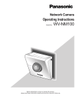
Network camera
Operating Instructions
Model No.
WV-NP244
244
-NP
WV
LOC
K
(Lens is option.)
Before attempting to connect or operate this product,
please read these instructions carefully and save this manual for future use.
CONTENTS
Preface ............................................................................................................................ 3
About these operating instructions .............................................................................. 3
Trademarks and registered trademarks ...................................................................... 3
Monitor Images on a PC .................................................................................................. 4
Monitor images from a single camera ......................................................................... 4
Monitor images from multiple cameras ....................................................................... 9
Action at an Alarm Occurrence ....................................................................................... 10
Transmit Images onto an FTP Server ............................................................................. 11
Transmit an alarm image at an alarm occurrence (Alarm image FTP transmission) .. 11
Transmit images at a designated interval or period (FTP periodic transmission) ....... 11
Save images on the SD memory card when failed to transmit images by the
FTP periodic transmission function ............................................................................ 12
About the Network Security of the Camera ..................................................................... 14
Equipped security functions ........................................................................................ 14
Display the Setup Menu and Configure the Settings of the Camera using a PC ............ 15
How to display the setup menu ................................................................................... 15
How to operate the setup menu .................................................................................. 16
Configure the basic settings of the camera [Basic setup] ........................................... 19
Configure the settings relating to images and audio [Camera setup] ......................... 22
Configure the multi-screen settings [Multi-screen setup] ............................................ 27
Configure the alarm settings [Alarm setup] ................................................................. 28
Configure the settings relating to the authentication [Authentication setup] ............... 35
Configure the settings of the servers [Server setup] ................................................... 37
Configuring the network settings [Network setup] ....................................................... 39
Maintenance of the camera [Maintenance] ................................................................. 45
About the Displayed System Log .................................................................................... 48
Troubleshooting ............................................................................................................... 50
2
Preface
About these operating instructions
There are 2 sets of operating instructions for the WV-NP244 as follows.
• Operating Instructions (book)
• Operating Instructions (PDF, these operating instructions)
These operating instructions contain descriptions of how to operate this product using a PC via a network and of
how to configure the settings.
Refer to the operating instructions (book) for descriptions of how to install this product and of how to connect to a
network.
Adobe® Reader is required to read these operating instructions (PDF). When the Adobe® Reader is not installed on
the PC, download the latest Adobe® Reader from the Adobe web site and install it.
Trademarks and registered trademarks
• Adobe, Adobe logos, and Acrobat are registered trademarks of Adobe Systems Incorporated in the U. S. and/ or
other countries.
• SD logo is a trademark.
• Other names of companies and products contained in these operating instructions may be trademarks or registered trademarks of their respective owners.
3
Monitor Images on a PC
The following are descriptions of how to monitor images from the camera on a PC.
Monitor images from a single camera
Step 1
Start up the web browser.
Step 2
Enter the IP address designated using the Panasonic IP
setup software in the address box of the browser.
(Example: http://192.168.0.10)
Important:
• When the HTTP port number is changed from "80"
to "81", enter the IP address of the camera after
"http://", for example "http://192.168.0.10:81".
• Configure the web browser to not use the proxy
server.
Step 3
Press the [Enter] key on the keyboard.
→ Click this button to display the "Live" page.
Notes:
• When "ON" is selected for "User Authentication", the
authentication window will be displayed before displaying live images for the user name and password
entries. The default user name and password are as
follows.
User Name: admin
Password: 12345
To enhance the security, change the password for
the user "admin". It is recommended to change this
password periodically.
• When "Unicast" is selected for "Transmission type"
(☞ page 23), up to 8 users can access the camera
concurrently. Depending on the set values for "Total
bit rate" and "Max bit rate (per 1 client)", the maximum concurrent access number may be less than 8
users. When 8 users have been concurrently
accessing already, the access limit message will be
displayed for users who accessed subsequently.
• When "ON" is selected for "MPEG-4 transmission"
(☞ page 23), MPEG-4 image will be displayed.
When "OFF" is select, JPEG image will be displayed. It is possible to display JPEG image even
when "ON" is selected for "MPEG-4 transmission".
In this case, the refresh interval will be limited.
<Refresh interval (JPEG)>
When "ON" is selected for "MPEG-4 transmission"
JPEG (VGA): 5 fps
JPEG (QVGA): 10 fps
When "OFF" is selected for "MPEG-4 transmission"
JPEG (QVGA or QVGA): 30 fps
The refresh interval may be longer depending on a
network environment, PC spec, photographic subject, access traffic, etc.
Important:
When displaying multiple MPEG-4 images on a PC,
images may not be displayed depending on the performance of the PC.
Refer to the following page for further information about
the "Live" page.
4
About the "Live" page
!0 Alarm occurrence indication button
o Camera name
!1 Audio button
!2 One shot button
!3 Time and date
q [Live] button
w Setup button
!4 Main area
e Multi-screen buttons
r Image type buttons
t Image capture size buttons
y Zoom buttons
u Brightness buttons
i AUX buttons
q
[Live] button
Click this button to display the "Live" page. Refer to
page 7 for descriptions of how to operate the "Live"
page.
y
ZOOM buttons (*2)
Click the desire button to zoom in/out the displayed
image. To return the zoomed image to the original
size, click the [1] button.
w
[Setup] button (*1)
Click this button to display the setup menu.
u
Brightness buttons (*2)
Adjust the brightness of images.
e
Multi-screen buttons
Click the desired multi-screen (1-4 or 5-8) button to
display images on a multi-screen.
i
AUX buttons (*2)
Click the desired button to open/close the AUX connector.
r
Image type buttons
Click the desired button to change the image type to
be displayed. The selected button will turn green.
o Camera name
The set camera name will be displayed.
t
Image capture size buttons
These buttons will be displayed only when a JPEG
image is displayed. Click the desired button to display image with the desired image capture size. The
selected button will turn green.
!0
Alarm occurrence indication button (*2)
This button will be displayed and will blink when an
alarm occurred. When the button is clicked, the button will disappear. When "Latch" is selected for
"Alarm output setup", the alarm output connector will
be reset by clicking this button. (☞ page 30)
5
!1
Audio button (*3)
Click this button to turn on/off audio.
!2
One shot button
Click this button to take a picture (a still picture). The
picture will be displayed on a newly opened window.
!3 Time and date
Current time will be displayed in the set date/time
display format. (☞ page 19)
!4 Main area
Images from the camera will be displayed in this
area.
*1: Operable by only users whose access level is "1.
Administrator"
*2: Operable by only users whose access level is "1.
Administrator" or "2. Camera control" when "ON" is
selected for "User authentication" (☞ page 35).
*3: The access level to operate this button can be
changed by the settings of "Authentication" on the
[Audio] tab. (☞ page 26)
Refer to page 35 for further information about the
access level.
6
Available operations when live images are displayed
*1: Operable by only users whose access level is "1. Administrator"
*2: Operable by only users whose access level is "1. Administrator" or "2. Camera control" when "ON" is selected for
"User authentication" (☞ page 35).
*3: The access level to operate this button can be changed by the settings of "Authentication" on the "Audio" tab.
(☞ page 26)
Refer to page 35 for further information about the access level.
Operation
Description
Display the setup menu
(*1)
The letters "Setup" on the button will turn green and the setup
menu will be displayed.
To return to the "Live" page, click the [Live] button.
Display images on a multiscreen
Images from multiple cameras can be displayed on a multiscreen by registering cameras on the setup menu. (☞ page 9)
Display MPEG-4 image
The letters "MPEG-4" on the button will turn green and
MPEG-4 image will be displayed.
When "OFF" is selected for "MPEG-4 transmission" on the
setup menu, the [MPEG-4] button will not be displayed.
(☞ page 23)
Display JPEG image
The letters "JPEG" on the button will turn green and JPEG
image will be displayed.
Change the image capture
size (Image resolution)
The letters "VGA" on the button will turn green and images
will be displayed in VGA size.
The letters "QVGA" on the button will turn green and images
will be displayed in QVGA size.
* The image capture size can be changed only when displaying JPEG image.
Zoom in/out of image (*2)
The zoomed image will return to the original size. (Image displayed in the original size cannot be zoomed out.)
The zoomed image will return to the original size.
The displayed image will be zoomed in.
Change brightness (*2)
The displayed image will be darker.
Image will be displayed with the default brightness (0).
(☞ page 25)
The displayed image will be brighter.
Open/close the AUX connector (*2)
The AUX connector will open.
The AUX connector will close.
7
Operation
Description
Acknowledge alarm occurrences (*2)
This button will be displayed and will blink when an alarm
occurred. When the button is clicked, the button will disappear. When "Latch" is selected for "Alarm output setup", the
alarm output connector will be reset by clicking this button.
(☞ page 30)
Turn on/off audio (*3)
When this button is clicked, the button will turn into the
button and audio will not be heard.
When this button is clicked, the button will turn into the
button and audio will be heard.
* The [Audio] button will be displayed only when "ON" is
selected for "Mic mode" on the setup menu. (☞ page 26)
Display a still picture (one
shot)
8
When this button is clicked, a new window will open and the
still picture (one shot) displayed on the "Live" page will be displayed on it.
To save this picture on a PC, right-click on the image and
select "Save" on the displayed pop-up menu.
Monitor images from multiple cameras
Images from multiple cameras can be displayed on a multi-screen. Images from up to 4 cameras can be displayed
simultaneously. To display images on a multi-screen, it is necessary to register cameras in advance. 4 cameras can
be registered as a group and up to 2 groups (8 cameras) can be registered. (☞ page 27)
Important:
• Select "OFF" for both the user authentication and the host authentication of the camera to be registered.
(☞ pages 35 and 36)
• Only JPEG images can be displayed on a multi-screen. Audio will not be heard.
Step 1
Click the [Multi-screen] button.
→ Images from the registered cameras will be displayed
on a 4-split screen.
q To display images on a single screen, click the the
[1] button or [Live] button.
w Click a camera name. Live images from the camera
corresponding to the clicked camera name will be
displayed on the "Live" page of the newly opened
window.
9
Action at an Alarm Occurrence
The alarm action will be performed when the following alarm occur.
Alarm type
Terminal alarm: When connecting an alarm device such as a sensor to the alarm connector on the rear of the
camera, the alarm action will be performed when the connected alarm device activated.
VMD alarm: When a motion is detected in the set VMD area, the alarm action will be performed.
* VMD stands for "Video Motion Detection".
Command alarm: When received Panasonic alarm protocol from the connected device via a network, the alarm
action will be performed.
Action at an Alarm Occurrence
Display the [Alarm occurrence indication] button on the "Live" page. (☞ page 7)
The [Alarm occurrence indication] button will be displayed on the "Live" page at an alarm occurrence.
Note:
The [Alarm occurrence indication] button will be refreshed in 30 seconds intervals. For this reason, it may take a
maximum of 30 seconds until the [Alarm occurrence indication] button is displayed on the "Live" page at an alarm
occurrence.
Notify of alarm occurrences to the device connected to the alarm connector.
It is possible to output signals from the alarm connector on the rear of the camera and sound the buzzer when an
alarm occurs. The settings for the alarm output can be configured on the [Alarm] tab of the "Alarm setup" page.
(☞ page 28)
Transmit an image onto a server automatically
An alarm image can be transmitted at an alarm occurrence to the server designated in advance.
The settings required to transmit alarm image to a server can be configured on the [Alarm] tab of the "Alarm setup"
page (☞ page 28) and the [FTP] tab of the "Server setup" page (☞ page 38).
Notify of alarm occurrences by e-mail
Alarm mail (alarm occurrence notification) can be sent at an alarm occurrence to the e-mail addresses registered in
advance. Up to 4 addresses can be registered as recipients of the alarm mail. An alarm image can be transmitted at
an alarm occurrence to the server designated in advance. The settings for alarm mail can be configured on the
[Notification] tab of the "Alarm setup" page (☞ page 33) and the [Mail] tab of the "Server setup" page (☞ page 37).
Notify of alarm occurrences to the designated IP addresses (Panasonic alarm protocol)
This function is available only when Panasonic device, such as the network disk recorder, is connected to the system. When "ON" is selected for "Panasonic alarm protocol", the connected Panasonic device will be notified that the
camera is in the alarm state. The settings for Panasonic alarm protocol can be configured on the [Notification] tab of
the "Alarm setup" page. (☞ page 33)
10
Transmit Images onto an FTP Server
Images can be transmitted to an FTP server. By configuring the following settings, transmission of images captured
at an alarm occurrence or captured at a designated interval to an FTP server will become available.
Important:
When using this function, set the user name and password to restrict users who can log into the FTP server.
Transmit an alarm image at an alarm occurrence (Alarm image
FTP transmission)
An alarm image can be transmitted at an alarm occurrence to the FTP server. To transmit alarm images to an FTP
server, it is necessary to configure the settings in advance.
The settings for the FTP server can be configured on the [FTP] tab of the "Server setup" page. (☞ page 38)
The alarm image FTP transmission function can be turned on/off on the [Alarm] tab of the "Alarm setup" page.
(☞ page 28)
Note:
Depending on the network traffic, number of the transmitted images may not reach the set number of images to
be transmitted.
Transmit images at a designated interval or period (FTP periodic
transmission)
Images can be transmitted at a designated interval or period. To transmit images at a designate interval or period, it
is necessary to configure the settings in advance.
The settings for the FTP server can be configured on the [FTP] tab of the "Server setup" page. (☞ page 38)
On the [FTP] tab of the "Network setup" page, the FTP periodic transmission function can be turned on/off, and the
settings relating to schedules (periods) can be configured. (☞ page 43)
Notes:
• Depending on the network line speed or the network traffic, images may not be transmitted at the exact designated interval or period.
• When "ON" is selected for both of the alarm image FTP transmission function and the FTP periodic transmission
function, the alarm image FTP transmission function will be given priority over the FTP periodic transmission
function. For this reason, images may not be transmitted at the exact designated interval or period if alarms
occur frequently.
11
Save images on the SD memory card when failed to transmit
images by the FTP periodic transmission function
Images failed to transmit by the FTP periodic transmission can be saved automatically on the SD memory card. To
obtain the images saved on the SD memory card, use the Windows command prompt or FTP client software. The
obtained images can be browsed on a PC.
Important:
We make no guarantee for any damages of files on the SD memory card incurred by malfunction or error occurrence in files saved on the SD memory card regardless of what the cause may be.
Save images on the SD memory card
By configuring the following settings, saving images which had been failed to transmit to the FTP server using the
FTP periodic transmission function will become available.
About SD memory card: Use (☞ page 21)
File name: With time and date (☞ page 43)
Obtain images on the SD memory card
Step 1
Access the camera using the Windows command prompt or FTP client software.
→ The window with the user name and password entry fields will be displayed.
Step 2
Enter the user name whose access level is "1. Administrator" and its password.
→ Log in the camera.
Note:
The default user name with the access level "1. Administrator" and its password are as follows.
User Name: admin
Password: 12345
12
Step 3
Move the current directory to drive B and obtain images.
Notes:
• When logging in the camera, the current directory will be drive D. Images on the SD memory card can be found
in the "FTP" directory under drive B. Move to the "FTP" directory and obtain images.
<Directory structure of drive B>
Directory
Drive B
FTP
Directory
(year/month/day)
Directory
(hour/minute)
050101
0123
050102
:
:
:
:
An image failed to transmit by the FTP
periodic transmission function
(Example) img_05010101230000.jpg
↑ The image will be saved here.
LOG ← Destination of logs to be saved
Example: To obtain the image (img_05010101230000.jpg) using the Windows command prompt
1. Enter "c:\>ftp 192.168.0.10" and press the [Enter] key.
→ FTP connection will be established with "192.168.0.10".
2. Log in by entering the user name and the password.
3. Enter "ftp>cd B:\FTP\050101\0123" and press the [Enter] key.
→ The current directory will be "B:\FTP\050101\0123".
4. Enter "ftp>bin" and press the [Enter] key.
→ The transfer mode will be set to the binary mode.
5. Enter "ftp>get img_05010101230000.jpg" and press the [Enter] key.
→ The image will be obtained.
6. Log out by entering "ftp>bye" and press the [Enter] key.
• It is possible to delete images on the SD memory card using the Windows command prompt, etc.
13
About the Network Security of the Camera
Equipped security functions
The following security functions are featured in this camera.
q Access restrictions by the host authentication and the user authentication
It is possible to restrict users from accessing the camera by setting the host authentication and/or the user
authentication to on. (☞ pages 35 and 36)
w Access restrictions by changing the HTTP port
It is possible to prevent illegal access such as port scanning, etc. by changing the HTTP port number.
(☞ page 40)
Note:
When failed to pass the user authentication (authentication error) using the same IP address (PC) for 8 times
within 5 minutes, access to the camera will be denied for a while.
14
Display the Setup Menu and Configure the Settings of the Camera using a PC
The settings of the camera can be configured on the setup menu. The setup menu is operable by only users whose
access level is "1. Administrator".
How to display the setup menu
Step 1
Display the "Live" page. (☞ page 4)
Step 2
Click the [Setup] button on the "Live" page.
→ The window with the user name and password entry
fields will be displayed.
Step 3
Click the [OK] button after entering the user name and
the password.
→ Click this button to display the setup menu.
Refer to the next page for further information about
this menu.
15
How to operate the setup menu
When completing the setting items in field A, click
the [SET] button below field A (A-1). The edited setting items in field A will not be applied unless the
[SET] button below field A (A-1) is clicked.
In the same manner above, click the [SET] button
below field B (B-1) when completing the setting
items in field B.
Step 1
Click the desired button in the frame on the left of the
window to display the respective setup menu.
When there are tabs at the top of the setup page displayed in the frame on the right of the window, click the
desired tab to display and configure the setting items
relating to the name of the tab.
Step 2
Complete each setting item displayed in the frame on
the right of the window.
Step 3
After completing each setting item, click the [SET] button to apply them.
Important:
When there are two [SET] buttons (or [REG] buttons) or more on the page, click the respective button to the edited setting item.
<Example>
A
A-1
B
B-1
16
About the operation window
q [Live] button
!1 Status display
area
w [Basic setup] button
!2 Main area
e [Camera setup] button
r [Multi-screen setup] button
t [Alarm setup] button
y [Authentication setup]
button
u [Server setup] button
i [Network setup] button
o [Maintenance] button
!0 [Help] button
q
[Live] button
Click this button to display the "Live" page.
w
[Basic setup] button
Click this button to display the "Basic setup" page.
The basic settings such as time and date and camera name, and the settings relating to the NTP server and the SD memory card can be configured on
the "Basic setup" page. Refer to page 19 for further
information.
e
r
[Camera setup] button
Click this button to display the "Camera setup" page.
The settings relating to image from the camera such
as image quality and brightness, and the settings
relating to audio can be configured on the "Camera
setup" page. Refer to page 22 for further information.
[Multi-screen setup] button
Click this button to display the "Multi-screen setup"
page. The cameras to be used for the multi-screen
display can be registered on the "Multi-screen setup"
page. Refer to page 27 for further information.
t
[Alarm setup] button
Click this button to display the "Alarm setup" page.
The settings relating to alarm occurrences such as
settings for the alarm action at an alarm occurrence,
the alarm occurrence notification, and the VMD area
settings can be configured on the "Alarm setup"
page. Refer to page 28 for further information.
y
[Authentication setup] button
Click this button to display the "Authentication setup"
page. The settings relating to the authentication
such as users and PCs restrictions for accessing the
camera can be configured on the "Authentication
setup" page. Refer to page 35 for further information.
u
[Server setup] button
Click this button to display the "Server setup" page.
The settings relating to the mail server and the FTP
server to which the camera accesses can be configured on the "Server setup" page. Refer to page 37
for further information.
17
i
[Network setup] button
Click this button to display the "Network setup" page.
The network settings and the settings relating to
DDNS (Dynamic DNS), SNMP (Simple Network
management Protocol) and FTP (File Transfer
Protocol) can be configured on the "Network setup"
page. Refer to page 39 for further information.
o
[Maintenance] button
Click this button to display the "Maintenance" page.
System log check, firmware upgrade and initialization of the setup menu can be performed on the
"Maintenance" page. Refer to page 45 for further
information.
!0
[Help] button
Click this button to display the "Help" page.
!1 Status display area
The name of the camera whose settings currently
being configured, and date and time will be displayed.
!2 Main area
Pages of each setup menu will be displayed. There
are tabs for some setup menus.
18
Configure the basic settings of the camera [Basic setup]
The basic settings such as time and date and camera name, and the settings relating to the NTP server and the SD
memory card can be configured on the "Basic setup" page.
The "Basic setup" page has 3 tabs of the [Basic] tab, the [NTP] tab and the [SD memory card] tab.
Configure the basic settings [Basic]
Click the [Basic] tab on the "Basic setup" page. (☞ page 16)
The settings such as the camera name, time and date, etc. can be configured on this page.
[Camera title]
Enter the title of the camera. Click the [SET] button after
entering the title of the camera. The entered title will be
displayed in the status display area.
Number of characters for the camera title: 0 - 20
characters
Default: WV-NP244
[Time and date setup]
Enter the current time and date. When "12-hours" is
selected for "Time display", "AM" or "PM" can be selected.
Available range: 01/01/2005 0:00:00 – 12/31/2035
23:59:59:59
Default: 01/01/2005 0:00:00
[Time display]
Select "12-hours" or "24-hours". Enter the current hour
reflecting this setting when entering the current time and
date for "Time and date setup".
Default: 24-hours
[Date/time display format]
Select a date/time display format.
When "04/01/2005 13:10:00" is set for "Time and date
setup" after selecting "24-hours" for "Time display", time
and date will be displayed as follows respectively.
DD/MM/YYYY
01/04/2005 13:10
MM/DD/YYYY
04/01/2005 13:10
DD/Mmm/YYYY
01/Apr/2005 13:10
YYYY/MM/DD
2005/04/01 13:10
Mmm/DD/YYYY
Apr/01/2005 13:10
Default: MM/DD/YYYY
[Daylight saving (Summertime)]
Select "ON" or "OFF" to determine whether or not to
apply daylight saving time. Select "ON" or "OFF" to
determine whether or not to apply daylight saving time.
ON: Applies summer time. An asterisk (*) will be displayed on the left side of the displayed time and
date.
OFF: Does not apply summer time.
Default: OFF
[Link/Access LED]
Select "ON" or "OFF" to determine whether or not to
light the link LED, the access LED of the network connector, and the SD memory card error LED.
Select "ON" to check the network status by lighting the
LEDs. Select "OFF" to turn off the LEDs at all times.
However, the power indicator will light even when "OFF"
is selected.
Default: ON
19
Notes:
• Link LED: This LED will light when communication
with the connected device is available.
• Access LED: This LED will light when accessing to
a network.
• SD memory card error LED: This LED will light
when it is impossible to write data on the SD memory card.
Configure the settings relating to the NTP server [NTP]
Click the [NTP] tab on the "Basic setup" page. (☞ page 16)
The settings relating to the NTP server such as the NTP server address, port number, etc. can be configured on this
page.
Important:
When entering the host name for "NTP server
address", it is necessary to configure the DNS settings on the [Network] tab of the "Network setup"
page. (☞ page 39)
[NTP port]
Enter a port number to be used for the NTP server.
Available port number: 1 - 65535
Default: 123
[Time adjustment]
Select the time adjustment method from the following.
Time adjusted by the selected method will be used as
the standard time of the camera.
Manual setup: Time set on the [Basic] tab on the
"Basic setup" page will be used as the standard time
of the camera.
Synchronization with NTP server: Time automatically
adjusted by synchronizing with NTP server will be
used as the standard time of the camera.
Default: Manual setup
[NTP server address]
Enter the IP address or the host name of the NTP server.
Number of characters for the NTP server address:
1 - 128 characters
Default: (blank)
20
[Synchronization interval]
Select an interval (1 - 24 hours: in 1 hour intervals) of
synchronization with the NTP server.
Default: 1 hour
[Time zone]
Select a time zone according to the location where the
camera is in use.
Default: (GMT) Greenwich Mean Time: Dublin,
Edinburgh, Lisbon, London
Configure the settings relating to SD memory card [SD memory card]
Click the [SD memory card] tab on the "Basic setup" page. (☞ page 16)
The settings relating to the SD memory card can be configured on this page.
[Format]
To format the SD memory card, click the [Execute] button.
[About SD memory card]
Select "Use" or "Not use" to determine whether or not to
use the SD memory card.
Important:
• Before removing the SD memory card from the camera, it is necessary to select "Not use" first.
• After inserting the SD memory card, it is necessary
to select "Use" to use the SD memory card.
[Information about SD memory card]
Available size and the total size of the SD memory card
will be displayed.
Depending on the state of the SD memory card, the size
indications will differ as follows.
Indication
--------KB/--------KB
********KB/********KB
Important:
• Before formatting the SD memory card, it is necessary to select "Use" for "About SD memory card" on
the [SD memory card] tab of the "Basic setup" page
and "OFF" for "FTP periodic transmission" on the
[FTP] tab of the "Network setup" page.
• Format the SD memory card only by clicking the
[Execute] button on the setup menu. Otherwise, the
following functions using the SD memory card may
not work properly with this camera.
• Save/obtain images when failed to transmit to
the FTP server using the FTP periodic transmission function
• Save/obtain the system logs
• It is recommended to use Panasonic’s SD memory
card. Otherwise, the camera may not work properly
or performance deterioration may be caused.
• It is impossible to access the SD memory card in the
process of formatting.
• All data saved on the SD memory card will be deleted when the SD memory card is formatted.
• Do not turn the power of the camera off in the
process of formatting.
• After formatting the SD memory card, available size
may be smaller than the total size since the default
directory is automatically created in the SD memory
card.
Description
No SD memory card is inserted.
Failed to obtain available size
due to error, etc.
The SD card memory is unformatted, or locked, etc.
Note:
When the available size reached "0 KB", images will
not be saved on the SD memory card. It is recommended to check the available size of the SD card
memory periodically.
21
Configure the settings relating to images and audio [Camera
setup]
The settings relating images and audio such as brightness and image quality of JPEG/MPEG-4 can configured on
this page.
The "Camera setup" page has 3 tabs of the [JPEG/MPEG-4] tab, the [Camera] tab and the [Audio] tab.
Configure the settings relating to JPEG image [JPEG/MPEG-4]
Click the [JPEG/MPEG-4] tab on the "Camera setup" page. (☞ page 16)
Configure the settings such as "Refresh interval (JPEG)", "Image capture size" and "Image quality" on this page.
Refer to page 23 for further information about the settings relating to MPEG-4 images.
[Refresh interval (JPEG)]
Select an interval to refresh the displayed JPEG image
from the following.
0.1 fps/0.2 fps/0.33 fps/0.5 fps/1 fps/2 fps/3 fps/5 fps/
6 fps */10 fps */15 fps */30 fps *
Default: 5 fps
Note:
When "ON" is selected for "MPEG-4 transmission",
the refresh intervals may be longer than the set
value when the setting value with an asterisk (*) on
the right is selected.
[Image capture size]
Select "QVGA" or "VGA" for the image capture size of
MPEG-4 images.
Default: VGA
[Image quality]
Select image quality for JPEG images from the following.
0 Super fine/1 Fine/2/3/4/5 Normal/6/7/8/9 Low
Default: 5 Normal
22
Configure the settings relating to MPEG-4 image [JPEG/MPEG-4]
Click the [JPEG/MPEG-4] tab on the "Camera setup" page. (☞ page 16)
Configure the settings such as "Refresh interval (MPEG-4)", "Image capture size" and "Image quality" on this page.
Refer to page 22 for further information about the settings relating to JPEG images.
[Image capture size]
Select "QVGA" or "VGA" for the image capture size of
MPEG-4 images.
Default: VGA
[Image quality]
Select image quality of MPEG-4 images from the following.
Fine/Normal/Low
Default: Normal
[MPEG-4 transmission]
Select "ON" or "OFF" to determine whether or not to
transmit MPEG-4 images.
ON: Transmits MPEG-4 images.
OFF: Does not transmit MPEG-4 images.
Default: ON
Note:
When "ON" is selected for "MPEG-4" transmission,
displaying rather of MPEG-4 image or JPEG image
will be available. However, the refresh interval
(JPEG) may be longer than the set value when displaying JPEG images.
[Max bit rate (per 1 client)*]
Select a MPEG-4 bit rate per a client from the following.
64 kbps/128 kbps */256 kbps */512 kbps */1024 kbps */
1536 kbps */2048 kbps */3072 kbps */4096 kbps *
Default: 2048 kbps *
Note:
The MPEG-4 bit rate is synchronized with "Total bit
rate" on the [Network] tab of "Network setup" page.
(☞ page 39)
For this reason, the bit rate may be lower than the
value when the setting value with an asterisk (*) on
the right is selected.
[Refresh interval (MPEG-4)]
Select an interval (1 - 5 seconds) to refresh the displayed MPEG-4 images.
If using under the network environment with frequent
error occurrences, shorten the refresh interval for
MPEG-4 to diminish image distortions. However, the
refresh interval (MPEG-4) may be longer than the set
value when displaying JPEG images.
Default: 3 sec
[Transmission type]
Select a MPEG-4 transmission type from the following.
Unicast: Up to 8 users can access a single camera
concurrently.
Multicast: No concurrent access limitation for a camera.
Note:
Refer to page 4 for further information about the
maximum concurrent access number.
Default: Unicast
[Multicast address]
Enter the multicast IP address.
Images and audio will be transmitted to the designated
IP address.
Available address: 224.0.0.0 - 239.255.255.255
Default: 239.192.0.20
23
[Multicast port]
Enter the multicast port number (used to transmit
MPEG-4 images from the camera).
Available port number: 1024 - 50000 (Only even numbers are available.)
Default: 37004
[Multicast TTL]
Enter the multicast TTL value.
Available value: 1 - 254
Default: 16
Important:
• Depending on the PC in use for monitoring, the multicast port number may be already in use. In this
case, it may be impossible to monitor images.
Change the multicast port number.
• When transmitting MPEG-4 image via a network, the
transmitted image sometimes may not be displayed.
In this case, refer to the network administrator.
• When two network interface cards or more are
installed on the PC in use, the network interface
card(s) not used for receiving images should be
invalidated when displaying MPEG-4 images using
the multicast port.
24
Configure the camera settings such as image quality and brightness, etc. [Camera]
Click the [Camera] tab on the "Camera setup" page. (☞ page 16)
The following are descriptions of how to configure the settings relating to images such as brightness, etc.
[Sensitivity up]
Select the sensitivity from the following.
OFF: Does not use the sensitivity adjustment.
[x2]: Adjusts the sensitivity up to x2 automatically.
[x4]: Adjusts the sensitivity up to x4 automatically.
[x8]: Adjusts the sensitivity up to x8 automatically.
[x16]: Adjusts the sensitivity up to x16 automatically.
Default: OFF
Important:
When the sensitivity is incremented, the refresh
interval may be longer.
[Brightness]
17 steps (–8 - 8) are available for brightness. "–8" is the
darkest and "8" is the brightest.
Default: 0
[White balance]
Select the white balance adjustment method from the
following.
AUTO: Adjusts the white balance automatically.
HOLD: Fixes to the white balance applied when the
[SET] button is clicked.
Default: AUTO
[Aperture level]
9 steps (–4 - 4) are available for aperture level (sharpness). "–4" is the softest and "4" is the sharpest.
Default: 0
[Flicker-less mode]
Select "ON" or "OFF" to determine whether or not to use
the flicker-less mode. Normally, select "OFF". When
using the camera under fluorescent lamps and flickers
appear, select "ON".
Default: OFF
[Backlight compensation (BLC)]
Select "ON" or "OFF" to determine whether or not to
compensate backlight.
ON: Compensates backlight. (Suitable when the subject
has backlight.)
OFF: Does not compensate backlight. (Suitable when
the subject has light in the front.)
Default: OFF
[Light control (ALC/ELC)]
Select "ALC" or "ELC" for light control according to the
lens in use.
ALC: Select this when an auto iris lens (DC) is in use.
ELC: Select this when a fixed iris lens is in use.
Default: ALC
Important:
• When "ELC" is selected, "ON" for "Flicker-less
mode" will be unavailable.
• DC/video servo type lenses are not supported.
• When "ON" is selected for "Flicker-less mode", sensitivity may be decremented.
25
Configure the settings relating to audio [Audio]
Click the [Audio] tab on the "Camera setup" page. (☞ page 16)
The settings relating to audio can be configured on this page.
Note:
When a shorter interval is selected, delay time will
be shorter. When a longer interval is selected, audio
interruption may be diminished even though delay
time will be longer.
Select the interval according to the network environment.
[Authentication]
Select an access level for audio transmission from the
following. Refer to page 36 for further information about
the access level.
Level 1only/Level 2 or higher/All users
Default: All users
[Mic mode*]
Select "ON" or "OFF" to determine whether to turn on or
off audio on a PC.
ON: Transmits audio from the camera to the PC. Audio
can be heard with images on the PC. Images and
audio will not be synchronized.
OFF: Does not transmit audio from the camera to the
PC. Therefore, no settings and controls relating
audio will be invalidated.
Default: ON
[Audio bit rate]
Select "16 kbps" or "32 kbps" for audio bit rate.
Default: 32 kbps
[Audio sensitivity]
Select the sensitivity of the built-in microphone of the
camera from the following.
Low/Middle/High
Default: Middle
[Transmission interval]
Select an interval for audio transmission from the followings.
20 msec/40 msec/80 msec/160 msec
Default: 40 msec
26
Note:
Images and audio will not be synchronized.
Configure the multi-screen settings [Multi-screen setup]
The cameras to be used for the multi-screen display can be registered on this page.
Refer to page 16 for descriptions of how to display "Multi-screen setup" page.
[IP address]
Enter the IP address or the host name of the camera to
be used for the multi-screen. 4 cameras can be registered as a group and up to 2 groups (8 cameras) can be
registered.
When the HTTP port number for the camera had
been changed, enter as follows:
"IP address of the camera:port number", for example
"192. 168. 0. 10:8080".
Number of characters for the IP address: 1 - 128
characters
Note:
When using the host name, it is necessary to configure the DNS settings. (☞ page 40)
[Camera title]
The entered camera title will be displayed on a multiscreen.
Number of characters for the camera title: 0 - 20
characters
27
Configure the alarm settings [Alarm setup]
The settings relating to alarm occurrences such as settings for the alarm action at an alarm occurrence, the alarm
occurrence notification, and the VMD area settings can be configured on this page.
The "Alarm setup" page has 3 tabs of the [Alarm] tab, the [VMD area] tab and the [Notification] tab.
Configure the settings relating to the alarm action [Alarm]
Click the [Alarm] tab on the "Alarm setup" page. (☞ page 16)
The settings relating to the alarm action can be configured on this page. Refer to pages 29 and 30 for further information about the settings relating to the alarm image and the alarm out connector.
[Originating port number]
Select a port number to be used to receive the command alarm.
Available port number: 1 - 65535
Default: 8181
[Terminal alarm]
Select "ON" or "OFF" to determine whether or not to
receive the terminal alarm.
Default: OFF
[VMD alarm]
Select "ON" or "OFF" to determine whether or not to
perform the alarm action using the VMD function. Refer
to page 31 for descriptions of how to set the VMD
areas.
Default: OFF
[Command alarm]
Select "ON" or "OFF" to determine whether or not to
receive the command alarm.
The command alarm is the function that notifies of
Panasonic protocol alarm from the other cameras.
When "ON" is selected, alarm actions will be performed
between multiple cameras.
Default: OFF
28
Configure the settings relating to the alarm image [Alarm image setup]
Click the [Alarm] tab on the "Alarm setup" page. (☞ page 16)
The settings relating to the alarm image to be transmitted to the FTP server can be configured on this page. The
alarm image will be transmitted to the FTP server. To transmit alarm images to the FTP server, it is necessary to
configure the settings in advance. (☞ page 38)
Refer to pages 29 and 30 for further information about the settings relating to the alarm image and the alarm out
connector.
Important:
Depending on the network line speed or the network
traffic, images may not be transmitted at the exact
designated interval or period.
[Transmission interval]
Select a transmission interval for the alarm image FTP
transmission from the following.
0.1 fps/0.2 fps/0.33 fps/0.5 fps/1 fps
Default: 1 fps
[Number of images]
Select the number of images to be transmitted from the
following.
10 pics/20 pics/ 30 pics/50 pics/100 pics/200 pics/
300 pics/500 pics/1000 pics/2000 pics/3000 pics/
5000 pics
Default: 100 pics
[Recording duration]
Approximate time to be taken to save the set "number of
images" with the set "transmission interval" will be displayed.
[Alarm image FTP transmission]
Select "ON" or "OFF" to determine whether or not to
transmit the alarm image to the FTP server.
Default: OFF
[Image capture size]
Select "QVGA" or "VGA" for the image capture size of
images to be transmitted to the FTP server or of an
image to be attached to the alarm mail.
Default: VGA
[Directory]
Enter the directory name where the alarm images are to
be saved.
For example, enter "/ALARM" to designate the directory
"ALARM" under the FTP root directory.
Number of characters for the directory name: 0 - 256
characters
[File name]
Enter the file name used for the alarm image to be
transmitted to the FTP server. The file name will be as
follows.
["Entered file name" + "Time and date (year/month/day/
hour/minute/second)"] + "Serial number"
Number of characters for the camera location: 1 - 32
characters
29
Configure the settings relating to the alarm out connector [Alarm output setup]
Click the [Alarm] tab on the "Alarm setup" page. (☞ page 16)
The settings relating to the alarm out connector can be configured on this page. Refer to pages 29 and 30 for further
information about the settings relating to the alarm image and the alarm out connector.
Note:
When "Open" is selected, the alarm signal will be
output for around 20 seconds when the power of the
camera is turned on.
[Pulse width]
When "Pulse" is selected for "Alarm output", select an
pulse width.
Available pulse width: 1 - 120 sec
Default: 1 sec
[Alarm output setup]
Select "ON" or "OFF" to determine whether or not to
output the alarm signals to the alarm out connector
when an alarm is detected.
Default: OFF
[External terminal output setup]
Select "Latch" or "Pulse" for the alarm out connector at
an alarm occurrence.
Latch: When an alarm is detected, alarm output connector will be in the state selected for "Alarm output"
until the [Alarm reset] button is clicked.
Pulse: When an alarm is detected, alarm output connector will be in the opposite state to the "Alarm output" setting for the period set for "Pulse width".
Default: Latch
[Alarm Output]
Select "Open" or "Close" to determine whether to open
or close the alarm output connector when output the
alarm signals.
Open: The alarm out connector will open when output
the alarm signals. (Normally close)
Close: The alarm out connector will close when output
the alarm signals. (Normally open)
Default: Open
30
Set the VMD areas [VMD area]
Click the [VMD area] tab on the "Alarm setup" page. (☞ page 16)
The video motion detection areas can be set on this page.
When a motion is detected in the set area, the alarm action will be performed.
Set the VMD areas
Step 1
Set the video motion detection area by dragging the
mouse on the screen. When the [All areas] button is
clicked, the whole area will become the VMD area, and
"1 (White)" will be automatically applied to "Area".
→ The designated area will become the VMD area and
the outline will be displayed. When 2 - 4 VMD areas
are set, each area will be numbered in order.
The areas will be identified by the respective outline
colors.
Step 2
Select "ON" or "OFF" for "Status" of each VMD area.
When the [SET] button is clicked after selecting "OFF",
the outline will become the broken line and no alarm
action will be performed even when a motion is detected
in the area.
Step 3
Select the detection sensitivity from the following. The
selected detection sensitivity will be applied to all the
VMD areas.
High/Middle/Low
Default: Middle
Step 4
Click the [SET] button after completing the settings.
Important:
The setting will not be applied unless the [SET] button is clicked.
31
Delete the set VMD area
Step 1
Click the [Delete] button respective to the area to be
deleted.
→ The outline of the area will disappear.
Step 2
Click the [SET] button.
→ The deletion will be completed.
Important:
The deletion will not be completed unless the [SET]
button is clicked.
32
Configure the settings relating to the mail notification [Notification]
Click the [Notification] tab on the "Alarm setup" page. (☞ page 16)
The settings relating to the alarm mail can be configured on this page. To notify of an alarm occurrence by e-mail, it
is necessary to configure the settings of the mail server. (☞ page 37)
[Mail body]
Enter the mail body.
Number of characters for the mail body: 0 - 200 characters
[E-mail notification]
Select "ON" or "OFF" to determine whether or not to
notify of an alarm occurrence by e-mail at an alarm
occurrence.
Default: OFF
[Attach image]
Select "ON" or "OFF" to determine whether or not to
attach an image to the mail to be sent.
Default: OFF
Note:
The settings for "Image capture size" of "Alarm
image setup" on the [Alarm] tab (☞ page 29) will be
applied to the size of the image to be attached.
[Address]
Enter the destination mail address. Up to 4 destination
addresses can be registered.
To notify by e-mail, check the "Notification setup" checkbox respective to the desired address. To delete the
registered address, click the [DEL] button respective to
the desired address.
Number of characters for the destination mail
address: 3 - 128 characters
[Mail subject]
Enter the mail subject.
Number of characters for the mail subject: 0 - 50
characters
33
Configure the settings relating to Panasonic alarm protocol [Panasonic alarm
protocol]
Click the [Notification] tab on the "Alarm setup" page. (☞ page 16)
The settings relating to Panasonic alarm protocol can be configured on this page.
[Panasonic alarm protocol]
Select "ON" or "OFF" to determine whether or not to
notify of an alarm occurrence by Panasonic alarm protocol when an alarm is detected.
Default: OFF
[Destination port]
Select a destination port of the Panasonic alarm protocol from the following.
Available port number: 1 - 65535
Default: 1818
[Retry times]
Select a retry time of Panasonic alarm protocol.
Available retry times: 1 - 30
Default: 2
[IP address]
Enter the destination IP address of the Panasonic alarm
protocol from the following. Host name is unavailable for
the destination IP address. Up to 8 destination addresses can be registered.
To notify by Panasonic alarm protocol, check the
"Notification setup" checkbox respective to the desired
IP address. To delete the registered IP address, click
the [DEL] button respective to the desired IP address.
34
Configure the settings relating to the authentication
[Authentication setup]
The settings relating to the authentication such as users and PCs restrictions for accessing the camera can be configured on this page.
The "Authentication setup" page has 2 tabs of the [User] tab and the [Host] tab.
Configure the settings relating to the user authentication [User]
Click the [User] tab on the "Authentication setup" page. (☞ page 16)
The settings relating to the user authentication can be configured on this page. Up to 16 users can be registered.
[Access level]
Select the access level of the host from the following.
1. Administrator: Allowed all available operations of the
camera.
2. Camera control: Allowed to display images from the
camera and to control the camera. The camera setting configuration is unavailable.
3. Live only: Only displaying live images is available.
The camera setting configuration and camera control are unavailable.
Default: 3. Live only
[User authentication]
Select ON or OFF to determine whether or not to
authenticate the user.
Default: OFF
[User name]
Enter a user name.
Number of characters for the user name: 1 - 32 characters
Default: (blank)
Note:
By clicking [i] of "User name check", the registered
user can be selected and the selected user’s information can be checked.
The registered user will be displayed with the access
level. (Example: admin [1])
To delete the registered user, click the [DEL] button
after selecting the user to be deleted.
Important:
If all users whose access level is "1. Administrator"
is deleted, it will be impossible to configure the settings.
[Password] [Retype password]
Enter the password.
Number of characters for the password: 4 - 32 characters
Default: (blank)
Note:
When the user name already in use is entered and
the [REG] button is clicked, the respective user information will be overwritten.
35
Configure the settings relating to the host authentication [Host]
Click the [Host] tab on the "Authentication setup" page. (☞ page 16)
The settings to restrict PCs (IP address) to access the camera can be configured on this page.
[Access level]
Select the access level of the host from the following.
1. Administrator/2. Camera control/3. Live only
Refer to page 35 for further information about the
access level.
Default: 3. Live only
Note:
• By clicking [i] of "Host check", the registered host
can be selected and the selected host’s IP address
can be checked.
The registered IP address will be displayed with the
access level. (Example: 192.168.0.21 [1])
To delete the registered host, click the [DEL] button
after selecting the IP address to be deleted.
[Host authentication]
Select ON or OFF to determine whether or not to
authenticate the host.
Default: OFF
Important:
Before configuring the host authentication, it is necessary to register IP addresses of the PCs to be
allowed to access the camera and determine their
access levels. If "ON" is selected for "Host authentication" before registering the hosts (IP addresses), it
will be impossible to access the camera.
[IP address]
Enter the IP address of the PC to be allowed to access
the camera.
Host name is unavailable for the IP address.
Notes:
• When "IP address/subnet mask" is entered, it is possible to restrict PCs in each subnet.
For example, when "192. 168. 0. 1/24" is entered
and "2. Camera control" is selected for the access
level, the PCs whose IP address is between
"192.168.0.0" - "192.168.0.255" can access the
camera with the access level "2. Camera control".
• When the IP address already in use is entered and
the [REG] button is clicked, the respective host information will be overwritten.
36
Configure the settings of the servers [Server setup]
The settings relating to the mail server and the FTP server can be configured on this page.
The "Server setup" page has 2 tabs of the [Mail] tab and the [FTP] tab.
Configure the settings relating to the mail server [Mail]
Click the [Mail] tab on the "Server setup" page. (☞ page 16)
The settings relating to the mail server used to send the alarm mail can be configured on this page.
[Authentication]
Select the authentication method to send e-mails from
the following.
None: It is unnecessary to clear any authentication to
send e-mails.
POP before SMTP: It is necessary to clear the POP
server authentication first to use the SMTP server to
send e-mails.
SMTP: It is necessary to clear the SMTP server authentication to send e-mails.
Default: None
Note:
When you don’t know the authentication method to
send e-mails, refer to the network administrator.
[SMTP server address]*
Enter the IP address or the host name of the SMTP
server used to send e-mails.
Number of characters for the SMTP server address:
1 - 128 characters
[POP server address]*
When "POP before SMTP" is selected for "Authentication", enter the IP address or the host name of the POP
server.
Number of characters for the POP server address:
1 - 128 characters
* Important:
When entering the host name for "POP server
address", it is necessary to configure the DNS settings on the [Network] tab of the "Network setup"
page. (☞ page 40)
[User name]
Enter the user name to access the server.
Number of characters for the user name: 1 - 32 characters
[Password]
Enter the password to access the server.
Number of characters for the password: 0 - 32 characters
[Sender's mail address]
Enter the mail address of a sender.
Entered mail address will be displayed in the "From"
(sender) line of the sent mails.
Number of characters for the sender's mail address:
3 - 128 characters
37
Configure the settings relating to the FTP server [FTP]
Click the [FTP] tab on the "Server setup" page. (☞ page 16)
The settings relating to the FTP server used to transmit the alarm images can be configured on this page.
[FTP mode]
Select "Passive" or "Active" for the FTP mode.
Normally, select "Passive". When failed to establish the
connection, select "Active".
Default: Passive
[FTP server address]
Enter the IP address or the host name of the FTP server.
Number of characters for the FTP server address:
1 - 128 characters
Important:
When entering the host name for "FTP server
address", it is necessary to configure the DNS settings on the [Network] tab of the "Network setup"
page. (☞ page 40)
[User name]
Enter the user name (login name) to access the FTP
server.
Number of characters for the user name: 1 - 32 characters
[Password]
Enter the password to access the FTP server.
Number of characters for the password: 0 - 32 characters
[Control port]
Enter a control port number to be used for the FTP server.
Available port number: 1 - 65535
Default: 21
38
Configuring the network settings [Network setup]
The network settings and the settings relating to DDNS (Dynamic DNS) and SNMP (Simple Network management
Protocol) can be configured on this page.
The "Network setup" page has 3 tabs of the [Network] tab, the [DDNS] tab, the [SNMP] tab and the [FTP] tab.
Configure the network settings [Network]
Click the [Network] tab on the "Network setup" page. (☞ page 16)
The following information is required to configure the network settings.
Contact the network administrator or your Internet service provider.
• IP address
• Net mask
• Default gateway (when using the gateway server/router)
• HTTP port Number
• Primary DNS, Secondary DNS (when using DNS)
<Unavailable IP addresses>
0. *. *. *
*. *. *. 0
255. *. *. *
*. *. *. 255
127.0.0.1
Class D address (224.0.0.0 - 239.255.255.255)
Class E address (240.0.0.0 - 255.255.255.255)
[Net mask]
When not using the DHCP function, enter the net mask
of the camera.
Default: 255.255.255.0
[DHCP]
Select "ON" or "OFF" to determine whether or not to use
the DHCP function.
Default: OFF
[IP address]
When not using the DHCP function, enter the IP
address of the camera. Do not enter the IP address
already in use (for the PCs and the other network cameras).
Default: 192.168.0.10
[Default gateway]
When not using the DHCP function, enter the default
gateway of the camera.
Default: 192.168.0.1
<Unavailable IP addresses for the default gateway>
0. *. *. *
*. *. *. 0
255. *. *. *
*. *. *. 255
127.0.0.1
Class D address (224.0.0.0 - 239.255.255.255)
Class E address (240.0.0.0 - 255.255.255.255)
39
[HTTP port]
Assign the port numbers independently.
The following port numbers are unavailable since they
are already in use.
Available port number: 1 - 65535
Default: 80
<Port numbers already in use>
20, 21, 23, 25, 42, 53, 67, 68, 69, 110, 123, 161,
162, 995, 10669, 10670
[DNS]
Select "AUTO" or "MANUAL" to determine whether or
not to use the DNS. When "MANUAL" is selected, it is
necessary to configure the settings for the DNS.
When using the DHCP function, it is possible to obtain
the DNS address automatically by selecting "AUTO".
Refer to the network administrator for further information
about the settings.
Default: MANUAL
[Primary DNS], [Secondary DNS]
When "MANUAL" is selected for "DNS", enter the IP
address of the DNS. Refer to the network administrator
about the IP address of the DNS.
[Line speed]
Select the line speed for data transmission from the followings. It is recommended to use with the default setting "AUTO".
AUTO/100 MF (Mbps full-duplex)/100 MH (Mbps halfduplex)/10 MF (Mbps full-duplex)/10 MH (Mbps halfduplex)
Default: AUTO
[FTP access]
Select "Allow" or "Forbid" to determine whether to allow
or forbid the FTP access.
Default: Allow
[Total bit rate]
Select the total bit rate for data transmission from the
followings.
64 kbps/128 kbps/256 kbps/512 kbps/1024 kbps/
1536 kbps/2048 kbps/3072 kbps/4096 kbps/Unlimited
Default: Unlimited
40
Notes:
• When selecting "64 kbps", select "OFF" for "Mic
mode" on the "Audio" tab. (☞ page 26)
• When "64 kbps" is selected, it is impossible to carry
out the live-transmission of JPEG images and the
FTP periodic transmission simultaneously.
Notes:
• The port forwarding function changes a global IP address to a private IP address, and "Static IP masquerade"
and "Network Address Translation (NAT)" have this function. This function is to be set in a router.
• To access the camera via the Internet by connecting the camera to a broadband router, it is necessary to assign
a respective port number for each camera and address translation by using the port forwarding function. For further information, refer to the operating instructions of the broadband router in use.
Enter [Global IP address + :
(colon) + port number] in the
"Address" box of the browser
via the Internet.
vvv.xxx.yyy.zzz:82
vvv.xxx.yyy.zzz:81
Global address
for the WAN
vvv.xxx.yyy.zzz
Broadband router
Private address
for the LAN
vvv.xxx.yyy.zzz
Address translation using the port
forwarding function
vvv.xxx.yyy.zzz:82 → 192.168.0.2:82
Internet
(WAN)
LOCK
Cable modem
xDSL modem
Private address
192.168.0.2
Port number: 82
Address translation using the port
forwarding function
vvv.xxx.yyy.zzz:81 → 192.168.0.1:82
LOCK
Private address
192.168.0.1
Port number: 81
Configure the settings relating to DDNS [DDNS]
Click the [DDNS] tab on the "Network setup" page. (☞ page 16)
The settings relating to DDNS can be configured on this page.
When accessing the camera via the Internet from the network environment of which the global IP address is
obtained using DHCP, the DDNS function is necessary.
When using the DDNS function, it is possible to access with "Host name registered in the DDNS server. nmdns.
net". To use the DDNS function, it is necessary to connect to the dedicated DDNS server. Refer to the web site for
further information about the DDNS. Refer to the "Readme" file about the web site.
It is necessary to configure the host name, user name and password registered in the DDNS server.
[DDNS]
Select "ON" or "OFF" to determine whether or not to use
the DDNS function.
Default: OFF
[Host name]
Enter the host name to be used.
Number of characters for the host name: 1 - 64 characters
41
[User name]
Enter the user name (login name) to access the DDNS
server.
Number of characters for the user name: 1 - 32 characters
[Access interval]
Select the interval to access the DDNS server to check
the IP address and the host name from the following.
1 min/10 min/30 min/1 hour/6 hours/24 hours
Default: 1 hour
[Password]
Enter the password to access the DDNS server.
Number of characters for the password: 0 - 32 characters
Configure the settings relating to SNMP [SNMP]
Click the [SNMP] tab on the "Network setup" page. (☞ page 16)
The settings relating to SNMP can be configured on this page. It is possible to check the status of the camera by
connecting to the SNMP manager. When using the SNMP function, contact the network administrator.
[Camera location]
Enter the name of the location where the camera is
installed.
Number of characters for the camera location: 0 - 32
characters
Default: (blank)
[Contact (Destination address or phone number of
manager)]
Enter the mail address or the phone number of the
SNMP manager.
Number of characters for the destination address or
the phone number of manager: 0 - 255 characters
Default: (blank)
[Community name]
Enter the community name to be monitored.
Number of characters for the community name:
0 - 32 characters
Default: (blank)
Important:
When using the SNMP function, it is necessary to
enter the community name. When no community
name is entered, the SNMP function will not work.
[Camera title]
Enter a camera title to be used to manage the camera
with the SNMP function.
Number of characters for the camera title: 0 - 32
characters
Default: (blank)
42
Configure the settings relating to the FTP periodic transmission [FTP periodic
transmission]
Click the [FTP] tab on the "Network setup" page. (☞ page 16)
The settings relating to the periodic transmission of images to an FTP server can be configured on this page. To
transmit images to an FTP server periodically, it is necessary to configure the settings of the FTP server in advance.
(☞ page 38)
Refer to page 44 for descriptions of how to configure schedules of image transmission.
Important:
• Depending on the network line speed or the network traffic, images may not be transmitted at the exact designated interval or period.
• When "ON" is selected for both of the alarm image FTP transmission function and the FTP periodic transmission
function, the alarm image FTP transmission function will be given priority over the FTP periodic transmission
function. For this reason, images may not be transmitted at the exact designated interval or period if alarms
occur frequently.
Note:
Images failed to transmit by the FTP periodic transmission can be saved automatically on the SD memory card.
(☞ page 21)
[File name]
Enter the file name (name of the image file to be transmitted) and select the naming option from the following.
With time and date: File name will be ["Entered file
name" + "Time and date (year/month/day/hour/
minute/second)" + "Serial number"].
Without time and date: File name will be the characters entered for "File name" only. When "Without
time and date" is selected, the file will be overwritten
each time a file is transmitted newly.
Number of characters for the file name: 1 - 32 characters
Default: (blank)
[FTP periodic transmission]
Select "ON" or "OFF" to determine whether or not to
transmit images using the FTP periodic transmission
function.
When "ON" is selected, it is necessary to configure the
settings of the FTP server. (☞ page 38)
Default: OFF
[Directory]
Enter the directory name where the images are to be
saved.
For example, enter "/img" to designate the directory
"img" under the FTP root directory.
Number of characters for the directory name: 0 - 256
characters
Default: (blank)
[Interval]
Select the interval for the FTP periodic transmission
from the following.
1 sec/2 sec/3 sec/4 sec/5 sec/6 sec/10 sec/15 sec/
20 sec/30 sec/1 min/2 min/3 min/4 min/5 min/6 min/
10 min/15 min/20 min/30 min/1 hour/1.5 hours/2 hours/
3 hours/4 hours/6 hours/12 hours/24 hours
Default: 1 sec
[Image capture size]
Select "QVGA" or "VGA" for the image capture size of
the images to be transmitted by the FTP periodic transmission.
Default: VGA
43
Configure the schedule settings of the FTP periodic transmission [Schedule setup]
Click the [FTP] tab on the "Network setup" page. (☞ page 16)
The schedule settings of the FTP periodic transmission can be configured on this page. Refer to page 43 for further
information about the settings relating to the FTP periodic transmission.
How to configure the schedule settings
How to delete the set schedule
Step 1
Check the check box of the desired day of the week.
→ The selected day of the week will be validated for the
schedule.
Step 1
Uncheck the check box of the set day of the week.
Step 2
To designate time, click [i] and select the desired
"hour" and "minute".
When not designating time, check the checkbox of "24
hours".
Step 3
Click the [SET] button after completing the settings.
→ The result will be displayed at the bottom of the window.
44
Step 2
Click the [SET] button after completing the settings.
→ The result will be displayed at the bottom of the window.
Maintenance of the camera [Maintenance]
System log check, firmware upgrade, and initialization of the setup menu can be performed on this page.
The "Maintenance" page has 3 tabs of the [System log] tab, the [Upgrade] tab and the [Initialization] tab.
Check the system log [System log]
Click the [System log] tab of the "Maintenance" page. (☞ page 16)
Up to 4000 system logs can be saved on the SD memory card when the SD memory card is inserted after selecting
"Use" for "About the SD memory card" on the [SD memory card] tab (☞ page 21)
When "Not use" is selected for "About the SD memory card", up to 100 system logs can be saved on the built-in
memory of the camera.
When the saved system logs reached the maximum number, the older system logs will be overwritten by the newer
logs. In this case, the oldest log is the first to be overwritten.
The system logs will be displayed in 100 logs each.
When using the SD memory card, the logs will be saved even when the power of the camera is turned off. When not
using the SD memory card, the logs will be deleted when the power of the camera is turned off.
[Time & date]
Time and date at the error occurrence will be displayed.
[Error message]
The descriptions about the error will be displayed.
Refer to page 48 for further information about the system logs.
45
Upgrade the firmware [Upgrade]
Click the [Upgrade] tab of the "Maintenance" page. (☞ page 16)
The current firmware can be checked and upgraded to the latest version on this page. Contact the dealer for further
information about the firmware upgrade.
Step 4
Click the [Upgrade] button.
→ The confirmation window will be displayed. When
"Do not reset the settings after completing the
upgrade. " was selected, the confirmation window will
not be displayed.
[Model No. ], [MAC address], [Firmware version],
[IPL version]
Information of each item will be displayed.
How to upgrade the firmware
Step 1
Contact the dealer and download the latest firmware
onto a PC.
Step 2
Click the [Browse…] button and designate the downloaded firmware.
Step 3
Click the radio button respective to the desired option to
determine whether or not to initialize the settings after
the firmware upgrade.
Note:
Read the "readme" file provided with the firmware
first and determine whether or not to initialize the
settings after the firmware upgrade
46
Important:
• Upgrade the firmware using a PC in the same subnet as of the camera’s.
• Follow the instruction of the dealer when upgrading
the firmware.
• Use the designated file (extension:img) for the
firmware upgrade.
• The name of the firmware to be used for upgrade
should be "firmware. img".
• Do not turn the power of the camera off in the
process of upgrade.
• Do not operate the web browser (including adjusting
the window size) in the process of upgrade.
• The following network settings will not be initialized
when upgrade the firmware after selecting "Reset to
the default setting after completing the upgrade.
(Except the network settings)".
IP address, net mask, default gateway, HTTP port,
ON/OFF settings for DHCP, AUTO/MANUAL settings for DNS, DNS primary and secondary address,
line speed, total bit rate
Initialize/restart the camera [Initialization]
Click the [Initialization] tab of the "Maintenance" page. (☞ page 16)
Initialization of the setup data and HTML files of the camera and restarting of the camera can be performed on this
page.
[Restart]
Click the [Execute] button to restart the camera. The
camera will be inoperable for around 1 minute after the
restart just as when the power is turned on.
Note:
Turn on the power of the camera while holding down
the [INITIAL SET] button of the camera, and wait
around 5 seconds without releasing the [INITIAL
SET] button.
Wait around 30 seconds after releasing the button.
The settings including the network settings will be
initialized.
[Initialize setup data]
Click the [Execute] button to reset the settings to the
default settings. However, the network settings will not
be reset.
It is impossible to operate the camera for around 1
minute after the initialization.
[Initialize HTML data]
Click the [Execute] button to reset the HTML files to the
default settings. It is impossible to operate the camera
for around 1 minute after the initialization.
[Initialize setup data and HTML data]
Click the [Execute] button to reset the settings and the
HTML files to the default settings. However, the network
settings will not be reset. It is impossible to operate the
camera for around 1 minute after the initialization.
47
About the Displayed System Log
Error indications relating to SMTP
Category
POP3 server error
Content
Authentication error
Cannot connect to POP3 server
SMTP server error
Internal error
Authentication error
Description
Entered user name or password may be
incorrect. Check if the mail settings are configured correctly.
• The IP address of the server may be
incorrect. Check if the IP address of the
server is configured correctly.
• The POP3 server may be down. Ask the
network administrator.
Entered user name or password may be
incorrect. Check if the mail settings are configured correctly.
Connection error to DNS server
• The designated IP address of the DNS
may be incorrect. Check if the DNS settings are configured correctly.
• The DNS server may be down. Ask the
network administrator.
Connot connect to SMTP server.
• The IP address of the server may be
incorrect. Check if the IP address of the
server is configured correctly.
• The SMTP server may be down. Ask the
network administrator.
Other error
An error occurred in the mail function. Check
if the mail settings are configured correctly.
Error indications relating to FTP
Category
FTP server error
Content
Connection error to DNS server
Description
The FTP server or DNS server may be down.
Connot connect to FTP server.
Connection error
File transfer error
Passive mode error
Log out failed
• The FTP server settings may be incorrect.
• The settings relating to the indicated item
may be incorrect.
Directory change failed
User name and password isn't correct.
Internal error
48
Other error
The FTP server settings may be incorrect.
Error indications relating to DDNS
Category
Connection error
Internal error
Content
Cannot connect to DDNS server.
Description
• The designated IP address of the DDNS
may be incorrect. Check if the DDNS settings are configured correctly.
• The DDNS server may be down. Ask the
network administrator.
User name or password isn't correct.
Entered user name or password may be
incorrect. Check if the DDNS settings are
configured correctly.
IP address updated failed.
IP address update error occurred in the
DDNS server. Ask the network administrator.
Other error
An error occurred in the DDNS function.
Check if the DDNS settings are configured
correctly.
Error indications relating to NTP
Category
Connection error
Content
Cannot connect to NTP server.
Internal error
Other error
Time adjustment
Succeeded in the update. (NTP)
synchronizing with NTP
succeeded.
Description
• The IP address of the server may be
incorrect. Check if the IP address of the
server is configured correctly.
• The NTP server may be down. Ask the
network administrator.
• The designated IP address of the NTP
server may be incorrect. Check if the NTP
server settings are configured correctly.
• The NTP server may be down. Ask the
network administrator.
Time correction succeeded.
49
Troubleshooting
Before asking for repairs, check the symptoms with the following table.
Contact your dealer if a problem cannot be solved even after checking and trying the solution or if the problem is not
described below.
Symptom
Cause/solution
Reference
pages
• Is the LAN cable (category 5) is firmly connected to
the network connector on the rear of the camera?
Operating
instructions
(book)
• Is the link LED right by the network connector lit?
When it is not lit, connection to a LAN may not be
established or a network may be not working correctly. Check if the cables have any contact failure or if
the wiring is correct or not.
• Are the set IP addresses valid?
Cannot access from the
browser.
50
Operating
instructions
(book)
36, 39
• Are you accessing the wrong IP address?
Check the connection as follows:
With the Windows command prompt,
> ping "IP address set for the camera"
When the WV-NP244 replies, the camera is functioning normally.
If not, restart the WV-NP244 and proceed as follows
(1) Change the IP address by using the "Panasonic
IP Setup" software.
(2) Initialize the camera by pressing the [INITIAL SET]
button on the rear of the camera. The IP address
will return to the default setting "192.168.0.10".
47
• Is the same IP address provided to other devices?
Are there contradictions between the address and the
network subnet to be accessed?
<When the camera and the PC are connected in the
same subnet>
Are the IP addresses of the camera and the PC set in
a common subnet?Or is "Use Proxy Server" for the
settings of the browser checked?
When accessing the camera in the same subnet, it is
recommended to enter the address of the camera in
the "Don’t Use Proxy For These Addresses" box.
<When the camera and the PC are connected in the
different subnet>
Is the IP address of the default gateway set for the
camera correct?
–
Symptom
Cannot access from the
browser.
Cause/solution
Reference
pages
• Is the power of the camera on?
Check if the power of the camera is turned on.
Operating
instructions
(book)
• Is the viewer software installed on a PC?
Install the viewer software on a PC.
Operating
instructions
(book)
No image is displayed.
Images are displayed blurry.
The image is not being
refreshed.
• Is the lens cap detached?
Check if the lens cap is detached.
–
• Aren’t there dusts or dirt on the lens?
Check if there are dust or dirt on the lens.
–
• Is the focus adjusted correctly?
Check if the focus is adjusted correctly.
Operating
instructions
(book)
• Depending on the version of your browser, there
might be difficulties refreshing the picture and operating the camera.
It is recommended to use Internet Explorer 6.0 SP2.
Operating
instructions
(book)
• Depending on the traffic of the network or the concentration of access to the camera, there might be difficulties displaying the camera picture. Click the reload
button of the browser to request the camera picture to
be refreshed.
–
51
Symptom
Cause/solution
Reference
pages
• This may occur due to the display adapter and driver
combination.
When this occurred, update the driver of the display
adapter to the latest version first.
If updating the driver does not solve the problem,
adjust the hardware acceleration as follows.
1. Right-click on the desktop and select "Properties"
from the displayed pop-up menu.
2. Select "Settings" from "Display Properties", and
then click the [Advanced] button.
3. Click the [Troubleshoot] tab and disable the
DirectDraw acceleration by adjusting the level of
"Hardware acceleration".
When displaying MPEG4
images on two browser windows or more, images from
two cameras or more are
displayed in sequence on a
single browser window.
–
d
52
When using a PC on which Windows XP Service Pack2 (SP2) is installed
The following may occur during operation when using a PC on which Windows XP Service Pack2 (SP2) is installed.
Follow the instructions below when the following occurred. By performing the following solutions, other applications
and the security level may not be affected.
The “Information Bar” expressed in the following symptom and solutions will be displayed just below the address bar
only when there is information to communicate.
Information Bar
Symptom
Solutions
Reference
pages
The following message is
displayed on the information
bar.
"Pop-up blocked. To see
this pop-up or additional
options, click here…"
Click the information bar and select "Always Allow Popups from This Site…". The disalog window saying "Allow
pop-ups from this site?" will be displayed. Click the "Yes"
button.
–
Unnecessary status bar or
scroll bar is displayed on the
pop-up window.
Click "Internet Options" on the Tools menu of Internet
Explorer, and then click the "Security" tab. Then, click the
"Custom Level…" button to open the "Security Setting"
window. Under "Miscellaneous", select "Enable" for
"Allow script-initiated windows without size or position
constraints". Click the "OK" button.
The "Warning" window will be displayed. Click the "Yes"
button.
–
53
Panasonic System Solutions Company,
Unit Company of Panasonic Corporation of North America
Security Systems
www.panasonic.com/security
For customer support, call 1.877.733.3689
Executive Office: Three Panasonic Way 2H-2, Secaucus, New Jersey 07094
Zone Office
Eastern: Three Panasonic Way, Secaucus, New Jersey 07094
Central: 1707 N. Randal Road, Elgin, IL 60123
Southern: 1225 Northbrook Parkway, Suwanee, GA 30024
Western: 6550 Katella Ave., Cypress, CA 90630
© 2005 Matsushita Electric Industrial Co., Ltd. All Rights Reserved.
Panasonic Canada Inc.
5770 Ambler Drive,Mississauga,
Ontario, L4W 2T3 Canada (905)624-5010
http://www.panasonic.ca
Panasonic Sales Company
Division of Panasonic Puerto Rico Inc.
San Gabriel Industrial Park 65th Infantry Ave. KM. 9.5 Carolina
P.R. 00985(809)750-4300
N1105-1125
3TR004165BAA
Printed in Japan