1
User Manual
EURODESK SX3282
Ultra-Low Noise Design 32-Input 8-Bus Studio/Live Mixer with
XENYX Mic Preamplifiers and British EQs
behringer.com
2
EURODESK SX3282 User Manual
Table of Contents
Thank you........................................................................ 2
Important Safety Instructions....................................... 3
Legal Disclaimer.............................................................. 3
Limited Warranty............................................................ 3
1. Introduction................................................................ 5
2. SX3282 Overview........................................................ 6
3. Mono Input Channels................................................. 9
4. Stereo Input Channels................................................ 9
5. Subgroups and Inserts............................................. 10
6. Main Section............................................................. 11
7. Connections............................................................... 12
8. Setting Up................................................................. 15
9. Patchbay.................................................................... 15
10. Applications............................................................ 18
11. Technical Background............................................ 20
12. Expanding............................................................... 21
13. Modifications.......................................................... 21
14. Specifications.......................................................... 22
Thank you
Thank you for choosing the EURODESK SX3282 mixing console. Your new
EURODESK console provides incredible sound and features, including 32 inputs,
24 XENYX mic preamps with +48 V phantom power, warm and musical “British”
EQ, multiple routing options, and more. These features come packaged inside
a ruggedly constructed unit that will serve as the heart and soul of your studio,
live front-of-house, or monitoring rig for years to come.
But why bother with manuals? We know you want to get started right away,
but please read this manual carefully and keep it handy for ongoing reference.
These instructions show you all the inside features, tricks, and tips you need to
build the best possible sound with your new EURODESK console.
After all, it’s all about your sound.
behringer.com
3
EURODESK SX3282 User Manual
Important Safety
Instructions
Terminals marked with this symbol carry
electrical current of sufficient magnitude to
constitute risk of electric shock. Use only
high-quality commercially-available speaker cables with
¼" TS plugs pre-installed. All other installation or
modification should be performed only by
qualified personnel.
9. Do not defeat the safety purpose of the polarized
or grounding-type plug. A polarized plug has two blades
with one wider than the other. A grounding-type plug
has two blades and a third grounding prong. The wide
blade or the third prong are provided for your safety. If the
provided plug does not fit into your outlet, consult an
electrician for replacement of the obsolete outlet.
10. Protect the power cord from being walked on or
pinched particularly at plugs, convenience receptacles,
and the point where they exit from the apparatus.
11. Use only attachments/accessories specified by
the manufacturer.
12. Use only with the
cart, stand, tripod, bracket,
or table specified by the
manufacturer, or sold with
the apparatus. When a cart
is used, use caution when
moving the cart/apparatus
combination to avoid
This symbol, wherever it appears, alerts you
to the presence of uninsulated dangerous
voltage inside the enclosure - voltage that
may be sufficient to constitute a risk of shock.
This symbol, wherever it appears, alerts you
to important operating and maintenance
instructions in the accompanying literature.
Please read the manual.
Caution
To reduce the risk of electric shock, do not
remove the top cover (or the rear section).
No user serviceable parts inside. Refer servicing to
qualified personnel.
Caution
To reduce the risk of fire or electric shock,
do not expose this appliance to rain and
moisture. The apparatus shall not be exposed to dripping
or splashing liquids and no objects filled with liquids, such
as vases, shall be placed on the apparatus.
injury from tip-over.
13. Unplug this apparatus during lightning storms or
when unused for long periods of time.
14. Refer all servicing to qualified service personnel.
Servicing is required when the apparatus has been
damaged in any way, such as power supply cord or plug
is damaged, liquid has been spilled or objects have fallen
into the apparatus, the apparatus has been exposed
to rain or moisture, does not operate normally, or has
been dropped.
15. The apparatus shall be connected to a MAINS socket
outlet with a protective earthing connection.
16. Where the MAINS plug or an appliance coupler is
used as the disconnect device, the disconnect device shall
remain readily operable.
Caution
These service instructions are for use
by qualified service personnel only.
To reduce the risk of electric shock do not perform any
servicing other than that contained in the operation
instructions. Repairs have to be performed by qualified
service personnel.
1. Read these instructions.
2. Keep these instructions.
3. Heed all warnings.
4. Follow all instructions.
5. Do not use this apparatus near water.
6. Clean only with dry cloth.
7. Do not block any ventilation openings. Install in
accordance with the manufacturer’s instructions.
8. Do not install near any heat sources such as
radiators, heat registers, stoves, or other apparatus
(including amplifiers) that produce heat.
Limit
§ 1 Warranty
[1] This limited warranty is valid only if you purchased
the product from a BEHRINGER authorized dealer in the
country of purchase. A list of authorized dealers can be
found on BEHRINGER’s website behringer.com under
“Where to Buy“, or you can contact the BEHRINGER office
closest to you.
[2] MUSIC Group* warrants the mechanical and
electronic components of this product to be free of defects
in material and workmanship if used under normal
operating conditions for a period of one (1) year from
the original date of purchase (see the Limited Warranty
terms in § 4 below), unless a longer minimum warranty
period is mandated by applicable local laws. If the product
shows any defects within the specified warranty period
and that defect is not excluded under § 4, MUSIC Group
shall, at its discretion, either replace or repair the product
using suitable new or reconditioned product or parts.
In case MUSIC Group decides to replace the entire product,
this limited warranty shall apply to the replacement
product for the remaining initial warranty period, i.e.,
one (1) year (or otherwise applicable minimum warranty
period) from the date of purchase of the original product.
[3] Upon validation of the warranty claim, the repaired
or replacement product will be returned to the user freight
prepaid by MUSIC Group.
[4] Warranty claims other than those indicated above
are expressly excluded.
PLEASE RETAIN YOUR SALES RECEIPT. IT IS YOUR PROOF
OF PURCHASE COVERING YOUR LIMITED WARRANTY.
THIS LIMITED WARRANTY IS VOID WITHOUT SUCH PROOF
OF PURCHASE.
§ 2 Online registration
Please do remember to register your new BEHRINGER
equipment right after your purchase at behringer.com
under “Support” and kindly read the terms and conditions
of our limited warranty carefully. Registering your
purchase and equipment with us helps us process
your repair claims quicker and more efficiently.
Thank you for your cooperation!
§ 3 Return materials authorization
Legal Disclaimer
Technical specifications and appearance are subject to change without
notice. The information contained herein is correct at the time of printing.
All trademarks are the property of their respective owners. MUSIC Group
accepts no liability for any loss which may be suffered by any person
who relies either wholly or in part upon any description, photograph or
statement contained herein. Colors and specifications may vary slightly from
product. BEHRINGER products are sold through authorized dealers only.
Distributors and dealers are not agents of MUSIC Group and have absolutely
no authority to bind MUSIC Group by any express or implied undertaking
or representation. This manual is copyrighted. No part of this manual may
be reproduced or transmitted in any form or by any means, electronic or
mechanical, including photocopying and recording of any kind, for any
purpose, without the express written permission of Red Chip Company Ltd.
ALL RIGHTS RESERVED.
© 2010 Red Chip Company Ltd.
Trident Chambers, Wickhams Cay, P.O. Box 146,
Road Town, Tortola, British Virgin Islands
behringer.com
Limited Warranty
[1] To obtain warranty service, please contact the
retailer from whom the equipment was purchased.
Should your BEHRINGER dealer not be located in your
vicinity, you may contact the BEHRINGER distributor for
your country listed under “Support” at behringer.com.
If your country is not listed, please check if your problem
can be dealt with by our “Online Support” which may
also be found under “Support” at behringer.com.
Alternatively, please submit an online warranty claim at
behringer.com BEFORE returning the product. All inquiries
must be accompanied by a description of the problem
and the serial number of the product. After verifying
the product’s warranty eligibility with the original sales
receipt, MUSIC Group will then issue a Return Materials
Authorization (“RMA”) number.
Lega
4
EURODESK SX3282 User Manual
[2] Subsequently, the product must be returned in
its original shipping carton, together with the return
authorization number to the address indicated by
MUSIC Group.
[3] Shipments without freight prepaid will not
be accepted.
§ 4 Warranty Exclusions
[1] This limited warranty does not cover consumable
parts including, but not limited to, fuses and batteries.
Where applicable, MUSIC Group warrants the valves or
meters contained in the product to be free from defects in
material and workmanship for a period of ninety (90) days
from date of purchase.
[2] This limited warranty does not cover the product
if it has been electronically or mechanically modified
in any way. If the product needs to be modified or
adapted in order to comply with applicable technical
or safety standards on a national or local level, in any
country which is not the country for which the product
was originally developed and manufactured, this
modification/adaptation shall not be considered a defect
in materials or workmanship. This limited warranty does
not cover any such modification/adaptation, regardless
of whether it was carried out properly or not. Under the
terms of this limited warranty, MUSIC Group shall not
be held responsible for any cost resulting from such a
modification/adaptation.
[3] This limited warranty covers only the product
hardware. It does not cover technical assistance for
hardware or software usage and it does not cover
any software products whether or not contained in
the product. Any such software is provided “AS IS”
unless expressly provided for in any enclosed software
limited warranty.
[4] This limited warranty is invalid if the factoryapplied serial number has been altered or removed from
the product.
[5] Free inspections and maintenance/repair work
are expressly excluded from this limited warranty, in
particular, if caused by improper handling of the product
by the user. This also applies to defects caused by normal
wear and tear, in particular, of faders, crossfaders,
potentiometers, keys/buttons, guitar strings, illuminants
and similar parts.
[6] Damage/defects caused by the following conditions
are not covered by this limited warranty:
• improper handling, neglect or failure to operate the
unit in compliance with the instructions given in
BEHRINGER user or service manuals;
• connection or operation of the unit in any way
that does not comply with the technical or safety
regulations applicable in the country where the
product is used;
• damage/defects caused by acts of God/Nature
(accident, fire, flood, etc) or any other condition that
is beyond the control of MUSIC Group.
behringer.com
[7] Any repair or opening of the unit carried out by
unauthorized personnel (user included) will void the
limited warranty.
[8] If an inspection of the product by MUSIC Group
shows that the defect in question is not covered by the
limited warranty, the inspection costs are payable by
the customer.
[9] Products which do not meet the terms of this
limited warranty will be repaired exclusively at the buyer’s
expense. MUSIC Group or its authorized service center will
inform the buyer of any such circumstance. If the buyer
fails to submit a written repair order within 6 weeks after
notification, MUSIC Group will return the unit C.O.D. with
a separate invoice for freight and packing. Such costs will
also be invoiced separately when the buyer has sent in a
written repair order.
[10] Authorized BEHRINGER dealers do not sell new
products directly in online auctions. Purchases made
through an online auction are on a “buyer beware” basis.
Online auction confirmations or sales receipts are not
accepted for warranty verification and MUSIC Group will
not repair or replace any product purchased through an
online auction.
§ 5 Warranty transferability
This limited warranty is extended exclusively to the
original buyer (customer of authorized retail dealer) and
is not transferable to anyone who may subsequently
purchase this product. No other person (retail dealer, etc.)
shall be entitled to give any warranty promise on behalf
of MUSIC Group.
§ 6 Claim for damage
Subject only to the operation of mandatory applicable
local laws, MUSIC Group shall have no liability to the buyer
under this warranty for any consequential or indirect
loss or damage of any kind. In no event shall the liability
of MUSIC Group under this limited warranty exceed the
invoiced value of the product.
§ 7 Limitation of liability
This limited warranty is the complete and exclusive
warranty between you and MUSIC Group. It supersedes
all other written or oral communications related to this
product. MUSIC Group provides no other warranties for
this product.
§ 8 Other warranty rights and
national law
[1] This limited warranty does not exclude or limit the
buyer’s statutory rights as a consumer in any way.
[2] The limited warranty regulations mentioned herein
are applicable unless they constitute an infringement of
applicable mandatory local laws.
[3] This warranty does not detract from the seller’s
obligations in regard to any lack of conformity of the
product and any hidden defect.
§ 9 Amendment
Warranty service conditions are subject to change without
notice. For the latest warranty terms and conditions
and additional information regarding MUSIC Group’s
limited warranty, please see complete details online at
behringer.com.
* MUSIC Group Macao Commercial Offshore Limited of
Rue de Pequim No. 202-A, Macau Finance Centre 9/J, Macau,
including all MUSIC Group companies
5
EURODESK SX3282 User Manual
1. Introduction
Important notes concerning installation
1.1 The manual
◊ The sound quality may diminish within the range of powerful
◊ Reading this manual will make you aware of the many possibilities the
SX3282 offers you. Please keep this manual safely for future reference.
broadcasting stations and high-frequency sources. Increase the
distance between the transmitter and the device and use shielded
cables for all connections.
1.1.1 Nomenclature
1.2.3 Online Registration
Most specialist subjects are not really all that difficult provided you understand
the language used, and the vocabulary of mixing is pretty straight-forward.
Nevertheless it is as well to be clear about what certain terms mean. A “slot” in a
recorder will always be referred to as a track, while that in a mixer will invariably
be a channel. A group will always refer to a sub-mix of channels. Similarly the
term band will be mentioned only in conjunction with frequency.
Please register your new BEHRINGER equipment right after your purchase
by visiting http://behringer.com and read the terms and conditions of our
warranty carefully.
1.2 Before you get started
1.2.1 Shipment
Your product was carefully packed at the factory to ensure safe transport.
Nevertheless, if the box is damaged inspect the unit immediately for
signs of damage.
◊ If the unit is damaged please do NOT return it to us, but notify your
dealer and the shipping company immediately; otherwise, claims for
damage or replacement may not be granted.
◊ We recommend that you use a flight case to give the unit optimum
protection during use or transport.
◊ Always use the original box to prevent damage during
storage or transport.
◊ Make sure that children cannot play unsupervised with the
unit or its packaging.
◊ Please ensure proper disposal of all packing materials.
1.2.2 Initial operation
Ensure adequate air supply and to avoid overheating do not place the unit
near radiators etc.
!!
Caution
◊ Before you change the fuse, switch off the device and pull the plug to
avoid electric shock or damage to the device.
◊ Blown fuses must be replaced by fuses of the correct rating!
Please refer to the “Specifications” section for the applicable rating.
For connection to the mains use the enclosed power cord with cold connector
which complies with the relevant safety regulations.
◊ Please make sure that all devices are properly grounded. For your own
safety, never remove or disable the ground conductors from the devices
or on the power cords. The unit must always be connected to the mains
outlet with a protective grounding connection.
behringer.com
Should your BEHRINGER product malfunction, it is our intention to have it
repaired as quickly as possible. To arrange for warranty service, please contact
the BEHRINGER retailer from whom the equipment was purchased. Should your
BEHRINGER dealer not be located in your vicinity, you may directly contact
one of our subsidiaries. Corresponding contact information is included in
the original equipment packaging (Global Contact Information/European
Contact Information). Should your country not be listed, please contact the
distributor nearest you. A list of distributors can be found in the support area of
our website (http://behringer.com).
Registering your purchase and equipment with us helps us process your repair
claims more quickly and efficiently.
Thank you for your cooperation!
6
EURODESK SX3282 User Manual
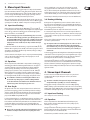
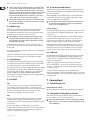
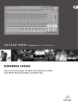
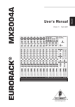
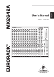
2. SX3282 Overview
Aux returns
2.1 Architecture
Four line-level stereo aux returns, each with Solo and Gain, are located above the
subgroup faders. Note that AUX RETURNS 1 and 2 are assignable to any mix bus.
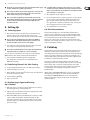
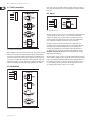
The SX3282 is a conventional split console. By this we mean that the inputs and
outputs occupy separate areas of the board. This makes for easier visualization
of signal path compared to an in-line design, which uses combined input/output
channels. The main section on the right hand side handles all the outputs
(as well as 4 stereo aux returns and a 2-track tape input), input channels are
located on the left.
The configuration is 32 into 8 into 2. This means that there are 32 channel inputs
in total (there are 24 mono and 4 stereo channels), assignable to 8 subgroup
buses (plus the main mix) which in turn may be blended into the main mix stereo
output. The subgroups (configurable as stereo pairs if required) are provided
for connecting to a multitrack tape recorder, or for use as a mixing aid during
mix-down or during a live concert. Every channel, and two out of four stereo
aux returns included in the SX3282, can access any or all of these subgroups
or the main mix directly, via comprehensive routing matrices. All channels
also have access to eight aux send buses. Each channel can access 6 aux sends
simultaneously. For each channel the 8 aux sends are switchable between two
configurations: six pre- and two post-, or six post- and two pre-fader, for live or
studio operating environments respectively.
Input channels
The first 24 input channels are mono, with a choice of balanced mic
(XLR, +48 V phantom power switchable) or line (¼" TRS) inputs, both with
exceptional gain architecture. A further 8 line inputs are configured as 4 stereo
input channels, accepting all line level signals. Every channel has mute, Solo/PFL
and comprehensive EQ. A high-quality 60 mm fader feeds the main mix and/or
subgroup buses via subgroup- and mix-assign switches. A constant-power
channel Pan also selects between odd and even-numbered subgroup buses.
Subgroups
For ease and flexibility of mixing, eight mono subgroups with Pan and Solo are
provided. Each has its own individual output, and each may also be assigned to
the main mix.
Aux sends
There are eight master aux send outputs, each with Solo and Gain.
behringer.com
Stereo aux returns
At the main section’s top end (middle) you will find four stereo aux returns,
each with Solo and Level control. AUX RETURN 3 and 4 are hard-wired to the
main mix, while AUX RETURNS 1 and 2 can be switched to either main mix or the
subgroups and therefore are equipped with a BALANCE control.
Main mix output / additional features
Main mix output level is being controlled via a pair of high-quality 60 mm faders.
The main section also includes an assignable headphones output with LEVEL,
a 2-track tape return assignable to the control room/monitors, and a solo output,
adjustable for audition level and switchable between the solo and PFL function.
The monitor (or control room) output is independently adjustable for level,
and the integral talkback mic is routable to 6 of the 8 aux buses, i.e. all possible
pre-fader (cue) sends. A BNC connector is provided for a gooseneck lamp for
those dark winter’s night mixes.
Inserts
Mono channels, subgroups and the main mix all have insert points for patching in
dynamics processors etc.
2.2 Metering
All input channels have signal and overload LEDs, while the L and R output has a
pair of 12 digit bargraph meters. The main mix (L/R) meters also have clip LEDs
(+28/22 dB: balanced/unbalanced), and double up as mono PFL or stereo solo
meters, or 2-track return meters (in general, what you hear is what you see).
During Solo/PFL only the main mix bargraph meters illuminate.
◊ The master clip LEDs (+22 dBu) should never be allowed to illuminate.
If they do, reduce either the MAIN MIX fader or the group(s) and/or
channel fader(s), or (as a last resort) the channel input gain(s).
Maybe it’s time to do a round of PFL metering.
◊ In Solo/PFL mode a 0 dB meter reading matches an internal operating
level of 0 dBu (0.775 V). However, when looking at the mix, 0 dB is
referenced to +4 dBu, the 2-track operating level. I.e. if only one signal
is present in the main mix bus, soloing that signal will cause the meter
reading to increase by +4 dB.
7
EURODESK SX3282 User Manual
[53]
[52]
[51] [50] [49] [48] [47] [46] [45]
[44] [43] [42]
[41]
[1]
[2]
[40]
[3]
[4]
[5]
[6]
[7]
[39]
[38]
[37]
[36]
[35]
[8]
[9]
[10]
[11]
[12]
[13]
[14]
[15]
[16]
[34]
[17]
[31]
[33]
[32]
[18]
[19]
behringer.com
[20]
[21] [22] [23]
[24] [25]
[26] [27]
[28]
[29] [30]
8
EURODESK SX3282 User Manual
[54]
[55]
[56]
[67]
[66]
[65]
[57]
[58]
[68]
behringer.com
[69] [70]
[59]
[71]
[60]
[61]
[62]
[63]
[64]
9
EURODESK SX3282 User Manual
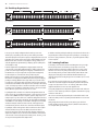
3. Mono Input Channels
Each channel comes with a balanced line input on ¼" TRS jack, and an XLR mic
input. Press the Phantom switch [71] at the back panel if required. The mic amp
circuit has an unusually wide gain range [1] } from 10 dB to 60 dB, is of extreme
low-noise design, and utilizes high-current conjugate pair vintage transistor
circuitry to deliver an incredibly warm and transparent sound.
When a jack is plugged into the balanced (self-unbalancing) line input, the gain
structure is such that it can match any line level from +10 to -40 dBu. The crucial
operating levels +4 dBu and -10 dBV are clearly and accurately legended ({[1}] ).
3.1 Input Level Setting
Channel input level is determined by the GAIN trimpot {[1}] . Use Solo/PFL [13]
to accurately monitor the channel input on the left/right master output bargraph
meters. This also sends the Solo/PFL-ed signal to the left and right speakers.
Channel Solo [13] has an associated LED [14] .
◊ For level-setting (as opposed to localized listening) choose to use the
Mono PFL bus rather than the post-fader (post-channel pan) stereo solo
bus (Channel MODE switch [38] not depressed). Solo/PFL never interrupts
the mix at the main recording outputs. It follows that aux sends and
subgroups must also be unaffected, since they contribute directly to
the main mix.
In addition to switchable Solo/PFL metering, a couple of channel LEDs ( [10] / [12] )
illuminate when a signal is present (-20 dB), or if a channel is going into overload.
These LEDs are particularly useful when using extreme EQ settings, or adding a
dynamics processor via an insert.
You do not want the overload light to come on except very intermittently during
a take or a mix. If it does light persistently, reduce input gain (see also the
essential section 8 “Setting up”).
3.2 Equalizer
All mono input channels are fitted with a semi-parametric 3-band EQ, plus a
switchable low-cut filter for eliminating unwanted subsonics. The upper {[2}]
and lower {[5}] shelving controls have their frequencies fixed at 12 kHz and
80 Hz respectively. The midrange control {[3}] is semi-parametric with a
peaking response, Q fixed at 2 octaves, sweepable from 100 Hz - 8 kHz ({[4}]).
All three bands have up to 15 dB of cut and boost, with a center detent for
“off”. Thirdly, there is a steep high pass (low-cut) filter {[6]}, slope @ 18 dB/oct,
for reducing floor rumble, breath noise and popping, woolly bottom end etc.
◊ The combination of shelf boost at 80 Hz together with low-cut at
75 Hz results in a peaking response, useful for adding warmth to
vocals and instruments, and a firm bottom to kick drums and basses,
without losing control of low frequency speaker cones.
3.3 Aux Sends
All eight aux sends {[7] are mono and post-EQ. Aux sends 1 & 2 are fixed to be
pre-fader for cueing purposes, while 3 & 4 are fixed post-fader for sending to
effects etc. A shift switch [{8]} toggles the third pair of aux send potentiometers
between two bus pairs (5 & 6 or 7 & 8). These four aux sends are switchable
pre/post-fader en bloc using the PRE switch {[9}].
For almost all FX send purposes, you will want aux sends to be post-fader, so that
when a fader level is adjusted, any reverb send from that channel follows the
fader. Otherwise, when the fader is pulled down, the reverb from that channel
would still be audible. For cueing purposes, aux sends will usually be set
pre-fader, i.e. independent of the channel fader (depress PRE switch {[9}] for aux
sends 5/6/7/8).
◊ Most reverbs etc. internally sum up the left and right inputs. The very
few that do not may be driven in true stereo by using 2 aux sends.
There is +15 dB of gain on every aux send. Such a high boost is usually
only appropriate where the channel fader is set around -15 dB or lower.
Here, an almost exclusively wet signal will be heard. In most consoles, such a
wet mix requires the use of a pre setting for the channel aux send, losing fader
control. With the SX3282 you can have a virtually wet mix with fader control.
Channels may be altered for pre-EQ aux sends (see section 13 “Modifications”).
3.4 Routing & Muting
Routing means selecting which bus you want a channel to address. There are
five stereo buses in the SX3282 (plus a stereo solo bus). Main mix and the four
subgroup pairs are selected by five assign switches [18]. Solo/PFL we encountered
in the section on input level setting (3.1).
Channel PAN [11] positions the output of the channel in the stereo field.
Its constant-power design ensures there are no level discrepancies whether a
signal is hard-panned, center-stage, or somewhere in-between. Such pin-point
accuracy will be a revelation if you have been working on consoles with lower
quality circuits.
All stereo buses follow channel Pan. Usually, only one of L-R, 1-2, 3-4 etc. will be
selected for a particular channel.
◊ An exception to this rule is when laying down voice takes. It is often
convenient to have the mic channel(s) routed to all potential take
tracks simultaneously, since you are often dropping in quickly between
four or more tracks. It means one less button to press each time you
switch tracks.
Level to the group and main left and right buses is ultimately determined by the
channel fader [17]. This is designed to give a smooth logarithmic taper of a type
more usually associated with megabuck consoles. The low level performance
particularly is far smoother than that of a “normal budget” fader.
The mute button [15], like that for Solo [13] is ergonomically placed immediately
above the channel fader, and has an associated LED [16] for excellent visual status
indication of this much-used feature. Engaging mute is equivalent to setting a
fader level of minus infinity. It follows that pre-fader aux sends are unaffected by
application of mute.
4. Stereo Input Channels
Each stereo channel comes with two line level inputs on ¼" jacks, for left
and right signals. When only the left input is connected, the channel
operates in mono.
◊ This feature is disabled, if the inputs and outputs of the SX3282 are
wired permanently to a patchbay (see section 9 “Patchbay”).
Channel input sensitivity is variable between -20 and +20 dB by adjusting
GAIN [1}] , enabling a perfect match with all common line-level sources including
multitrack tape outputs, MIDI and other electronic instruments and effects units,
all of which are normally designed to operate at either +4 dBu or -10 dBV.
4.1 Input Level Setting
This is exactly as for a mono channel (see section 3.1).
4.2 Equalizer
All stereo input channels are fitted with four-band, fixed-frequency EQ.
Bands 1 and 4 are shelving, while bands 2 and 3 have a peaking response,
with their Q set at 2 octaves.
The upper {[2]} and lower {[5}] shelving controls have their turnover frequencies
fixed at 12 kHz and 80 Hz, whereas the midrange controls [53]} and [52] have their
bell center frequencies set at 8 kHz and 800 Hz.
All bands have up to 15 dB of cut and boost, with a center detent for “off”.
behringer.com
10
EURODESK SX3282 User Manual
◊ A stereo equalizer is generally preferable to using two mono equalizers
when EQ-ing a stereo signal, as often discrepancies between left and
right settings can occur.
4.3 Aux Sends
Keyboard
These are the same as for mono channels (see section 3.3).
4.4 Routing & Muting
The only difference here from the mono channel described in 3.4 is in the
implementation of the pan control. When a channel is run in mono, there is no
difference at all.
ULTRACURVE PRO DEQ246
Stereo Channel/Input
In stereo operation however, this control functions as a BALANCE control [19],
determining the relative balance of the left and right channel signals being
sent to the left and right main mix buses, or odd and even subgroup buses.
For example, with the balance control turned fully clockwise, only the
right portion of the channel’s stereo signal will be routed to any or all of
buses R, 2, 4 etc.
SX3282
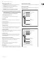
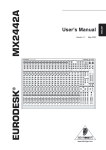
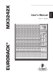
5. Subgroups and Inserts
Fig. 5.1: Inserting into a stereo channel
5.1 Subgroups
◊ Please note that we didn’t draw the ground/screen connection in the
The principal routes to multitrack are via the subgroup outputs. There are eight
mono (or four stereo) subgroups. All channels can access all of them, as can aux
returns 1 and 2 ( [47] ). Subgroup level is determined by the Subgroup fader [20],
while the signal level may be accurately checked by solo-ing ( [22] ).
following graphics to keep them as simple as possible.
◊ If you want to insert an external EQ or dynamics processor post-EQ,
a subgroup insert should be used as follows:
Subgroup outputs can also be assigned to the main mix during mixdown by
pressing the MAIN MIX switch [21] , in which case stereo position in the L R mix is
determined by the subgroup’s PAN pot [23] .
◊ Try inserting compression/de-essing/an exciter or a noise gate across
grouped signals (e.g. backing vocals, drums, layered synths).
◊ Try merging a dry signal with a little wet, then compressing the sum
heavily. Though the reverb proportion will be low when a signal is
present, the resultant reverb tail pumped up by the compressor at the
start of each silence will give the illusion that the reverb was massive
at the time. (The listener will be left wondering how the singer could
sound so clear in such a wet acoustic!)
Channel 1
Input
Subgroup 1
Insert
5.2 Insert Points
Insert points are useful for adding dynamic processing or equalization to a
channel, a group, or the mix. Unlike reverbs etc., which are usually added to
the dry signal, dynamic processing is normally applied across an entire signal.
Here an aux send would be inappropriate. Instead the signal is intercepted
somewhere along the channel, fed through the dynamics processor and/or EQ,
then returned to the console at the same point where it left. The insert point is
normalized, i.e. the signal is only interrupted when a jack is plugged into it.
All mono input channels have got insert points, as have the subgroups and the
main mix. Each insert point is accommodated on a single TRS jack socket wired
tip = send, ring = return, sleeve = ground/screen. Inserts are always pre-fader,
and also pre-EQ/pre-aux sends for channels.
◊ If you want to insert a dynamics processor etc. into one of the stereo
channels, it must be done between the source output and the SX3282,
as these channels have no bona-fide insert point.
behringer.com
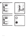
Send
Return
ULTRACURVE PRO DEQ2496
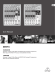
Fig. 5.2: Inserting an external EQ / dynamics processor post channel EQ
11
EURODESK SX3282 User Manual
In this arrangement you might find that compression tends to soften the
perceived amount of (especially treble) EQ applied. The solution here is to
apply more EQ. This creates a real ‘pressure’ sound, great for high energy music
such as dance.
In the above example, any aux sends to effects should be applied before
the EQ/dynamics processing takes place. If you want the aux sends to be
post-processing, you will need to address the signal to one of the subgroups and
then insert the EQ/dynamics processor between the corresponding subgroup
output (insert send) and a channel input (insert return).
You can now reclaim the channel 2 input as follows: By applying the channel’s
insert send you can route out an instrument’s signal being plugged into the line
input, treat it with an EQ/dynamics processor, and then reroute it via a subgroup
(insert return) to the master section.
An additional patch enables channel EQ to be placed onto a subgroup with
no reduction in the number of line inputs available, as well as providing an
opportunity to lead a signal pre-EQ into a subgroup. By inserting a plug into the
channel insert socket, the channel is interrupted between the gain pot and the
EQ. A signal which is being led into the channel’s mic-or line input is now guided
into the subgroup inserts input. It appears to be sensible to use this signal path
preferably for readily edited signals (e.g. tape tracks or post-EQ DI-outs from
instruments amplifiers), as there is no EQ in the subgroup signal path.
Subgroup 1
Insert Send
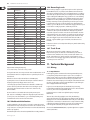
6. Main Section
6.1 Aux Masters
Aux sends
Much of the main section (situated left and below the bargraph meters) is taken
up by master aux sends and returns.
Stacked in a vertical column are eight master AUX SEND LEVEL pots [51], one for
each bus. Each has a gain structure of -oo to +15 dB. The extra 15 dB of gain
comes in once a knob passes a center detent (representing the ‘normal’ unity gain
position), enabling insensitive outboard FX to be properly driven. Each aux send
has a Solo button [50] , and, as with other areas of the mixer, a local Solo light [49] ,
which starts flashing when any of the aux master sends are solo-ed.
(This is to help you see exactly what has been solo-ed. Any experienced engineer
will have had occasion to painstakingly search through every solo button on
his / her console trying to find out why one of the main solo lights was flashing,
while the control room monitors remained silent!)
Aux returns
Across from the aux sends are the stereo aux returns. These can be thought of as
eight extra line inputs, configured as four stereo pairs. On these inputs there is up
to 20 dB of gain available. Alternatively, a mono (center-panned) signal may be
returned by plugging into the left aux return jack only.
◊ This feature is disabled if all line-level l/Os from the SX3282 are wired
Tip
Ring
permanently to a patchbay (see section 9 “Patchbay”).
Aux returns 1 & 2
Aux returns 1 and 2 have full group routing matrices to enable returning FX to
be sent to tape, plus main mix bus assignment. The functions for aux return 1
(mirrored by aux return 2) are: routing-switches [45] , Level [47] , Balance [48] and
Solo [46] . Level controls the amount of signal being blended into the mix or a
group, while balance controls the relative amounts of left and right processed
signal. Be sure to have balance control in center-position, if you’re not actually
working with it.
◊ As always, there are exceptions to the rule above. Some short stereo
Channel X
Insert Return
delay effects (say 30 ms to left, 50 ms to right) cause a psycho acoustic
effect where the earlier delay seems louder. A similar effect is
noticeable when harmonizing in stereo: a slight pitch shift upwards
will seem louder than one that goes down. In both cases use Balance
[48] to compensate. (An analogy comes from Greece: the columns of the
Parthenon in Athens are slightly bowed so as to appear straight.)
When carrying out the setup mentioned above or any other stereo imaging
exercise, don’t just rely on the control room monitors. Get a pair of headphones
and listen in stereo and in reverse stereo, to allow for any hearing discrepancy
between your ears.
Fig. 5.3: Making use of the channel EQ for shaping subgroup-signal by applying inserts
Aux returns 3 & 4
◊ SX3282 insert points are, of course, simultaneously inputs and outputs.
Aux returns 3 and 4 are the poor relations, with only a level pot [44] and Solo
switch [43] each. These are always assigned to the main bus.
For goodness sake, get them onto a patchbay, where they can appear
as independent sockets, and do away with all these fiddly Y-leads
that always seem to be the first to get knotted in the flightcase
(see section 9 “Patchbay”). Now it is possible to do the incredibly useful
patch shown in fig. 5.3 without having to make up what would amount
to a ring-to-tip, tip-to-ring stereo patch lead.
◊ Insert points may also be used as pre-EQ direct outputs without
interrupting the signal flow. See fig. 7.5 “Direct out connection”.
behringer.com
Solo
Below the aux returns 1/3 and 2/4 lies a local Solo LED [42] . This flashes whenever
a solo button in the column above is pressed.
12
EURODESK SX3282 User Manual
◊ There is no absolute reason why the send from aux 1 should feed into
a processor whose outputs are sent to the aux return 1. The processor
could just as easily be patched into the aux return 3, or even a pair of
channels. For many purposes, however, it is sensible to set up a default
patch where the aux sends and returns correspond. It is logical to
put your premier FX units into the aux 1 and aux 2 loops, since these
returns enable you to record to tape without repatching.
◊ Sometimes an engineer wants to narrow the stereo width of a reverb
field. To do this you will have to come back on channels, because they
have full panorama facilities.
6.2 Monitoring
Though most of you will want to audition the main mix most of the time,
there are exceptions. These include Solo/PFL and 2-track playback [30].
The bargraph meters follow whatever source is being auditioned (the meters
won’t make much sense if more than one source is selected).
◊ Altering what goes into the control room monitors does not affect
the signal from the main mix recording outputs. That offers to you
the opportunity to do a quick solo during a mix whenever you want
without having to start again!
The Monitor/Ctrl Level pot [28] sets the level to the control room monitors.
This is sourced post the main mix stereo fader setting. Your fades couldn’t be
heard otherwise.
Don’t rely on a single pair of loudspeakers to audition your mix. You’d better use a
variety of different speakers.
Lastly, there is a Mono button [29], useful for checking the phase correlation and/or
coherence of a stereo signal. Again, this does not affect the main mix output.
6.3 Headphones
The headphones may be sourced from the monitor/control room mix [27], and/
or from pre-fader aux sends 1/2 [26] or switchable pre/post aux sends 5/6 [25] for
artist cueing. Two headphones sockets are provided on the back panel.
The headphone mix level is controlled by a LEVEL pot [24] , and the gain is sufficient
to drive headphones directly. This is fine for a MIDI suite with overdub booth,
but for the bigger studio’s headphone network using a separate headphones
distribution amplifier like the Behringer POWERPLAY PRO‑XL HA4700 is
recommended. This can offer the added advantage of independent headphones
level control for every performer.
6.5 2-Track Input and Output
The 2-track input is on unbalanced RCA phono plugs, and is primarily made for
auditioning mix playback from tape. The 2-TRACK switch [30] routes this signal to
the control room monitors.
With the MON/CTR Level control [28] fully clockwise, your 2-track input will be
matched to the semi-professional level -10 dBV. For higher output recording
sources (e.g. +4 dBu) turn the level of [28] down.
◊ The 2-track input could usefully be connected to the output of a hi-fi
pre-amp or integrated amplifier, allowing you to easily audition a
variety of sources (e.g. CD, phono etc.).
2-track output
A pair of balanced XLR and jack connectors deliver the mix output to your 2-track
recorder (or PA system) at +4 dBu. Alternative RCA phono (-10 dBV) connectors
are provided, too.
Level to tape is ultimately determined by precision faders [31] . Main mix insert
points are provided for patching a gate, a compressor etc. pre-fader. This is
important: Connecting a compressor or gate after the 2-track output would
disrupt any attempt to acquiring a smooth fade using the output faders.
Although the 2-track output is primarily designed for recording, it can also be
used as a PA feed, or as a send to the input of your sampler. In fact up to three
simultaneous destinations can be serviced without resorting to a patchbay or
splitter leads—there are three separate 2-track outputs on your SX3282!
6.6 Talkback
The built-in flush-mounted mic [33] is activated by depressing the non-latching
talk switch [32] just above the MAIN MIX faders. Engaging talkback dims the
control room monitors, (not lights!) by -20dB to avoid feedback. This does not
affect the other talkback routes.
Talkback level is set by [37] , and the mic can be routed to any or all of auxes
1/2, 5/6 or 7/8 ( [36] , [35] , [34] ) —in other words every possible pre-fader (cue)
aux send—to enable you to talk to artists remotely through their headphones
or personal stage mixes.
Sometimes you will want a much higher rejection of feedback than a
flush-mounted talkback mic could ever provide. When running a live concert mix,
a dynamic mic plugged into a spare channel and routed to all the pre-fader sends
only will do the job.
6.4 Solo/PFL
7. Connections
Solo
7.1 SX3282 Back Panel
Solo is short for Solo-in-Place, and is the preferred method for auditioning
an isolated signal, or group of signals. Whenever a Solo button is pressed,
all unselected channels are muted in the monitors. Stereo panning is maintained.
The solo bus is derived from the output of the channel pans, aux sends,
stereo line inputs and subgroups, and is always post-fader.
PFL
Pressing the channel mode switch [38] once disengages the stereo solo bus,
and replaces it with a separate mono PFL (Pre-Fader Listen) bus. Now any
channel which is solo-ed, isn’t. It is PFL-ed instead. PFL should always be used
for gain-setting.
The channel mode (PFL or Solo) is indicated by a pair of status LEDs
(located below the bargraph meter [40] ), pot [39] controls the solo level, which will
normally be set to unity gain (center detent) to match the in-the-mix level
(see also the essential section 8 “Setting up”).
behringer.com
Phantom power switch
When using capacitor mics, +48 V DC can be switched globally on or off by [71].
7.2 Patchfield and Plug Wiring Scheme
Most of the inputs (inserts being the major exception) are balanced. Refer to
section 9 “Patchbay” if you are not sure what this means.
◊ Unbalanced equipment may be connected to balanced inputs/outputs.
Either use mono ¼" jacks or connect ring and barrel of TRS jacks (or pin
1 and 3 of XLR plugs).
13
EURODESK SX3282 User Manual
Mono input channels 1 - 24
Main output (TRS sockets)
• Insert points: unbalanced send and return on a single ¼" TRS socket,
Unbalanced ¼" TRS sockets, wired tip = hot (+ve), sleeve = ground/screen.
wired tip = send, ring = return, sleeve = ground/screen.
• Line inputs: balanced ¼" TRS sockets, wired tip = hot (+ve),
ring = cold (-ve), sleeve = ground/screen.
• Mic inputs: XLR-type connectors, wired pin 1 = ground/screen,
Main outputs (XLR)
Balanced XLR, wired pin 1 ground/screen, pin 2 hot (+ve), pin 3 cold (-ve).
Maximum level is +28 dBu.
2 = hot (+ve), 3 = coid (-ve), for balanced low-level operation.
◊ Care should be taken NOT to plug mics into the console (or stagebox)
Unbalanced ¼" TS connector
while the phantom power [71] is on. Also mute the monitor / PA speakers
when turning phantom power on or off. Allow 1 minute after powering
up for the system to equilibrate before setting input gains.
Strain relief clamp
Sleeve
Stereo input channels 25 - 32
Tip
Four stereo pairs. Unbalanced ¼" TRS sockets, wired tip = hot (+ve),
sleeve = ground/screen.
Aux sends
Sleeve
(ground/shield)
Unbalanced ¼" TRS sockets, wired tip = hot (+ve), sleeve = ground/screen.
Stereo aux returns
Four stereo pairs on balanced ¼" sockets, wired tip = hot (+ve), ring = cold (-ve),
sleeve = ground/ screen.
Tip
(signal)
Subgroup inserts
For inserting into a subgroup signal. Unbalanced send and return on a single
¼" TRS socket, wired tip = send, ring = return, sleeve = ground/screen.
Subgroup outputs
Fig. 7.1: ¼" TS connector
Balanced ¼" TRS connector
Primarily designed for feeding a multitrack recorder. Unbalanced ¼" TRS sockets,
wired tip = hot (+ve), sleeve = ground/screen.
strain relief clamp
sleeve
2-track in / out
ring
tip
RCA sockets for use with tape recorders etc., signal = main mix. Use custommade RCA cables for the 2-Track in/out traffic (center post = signal (+ve),
sleeve = ground/screen).
Monitor & control room outputs
sleeve
ground/shield
Will feed a pair of speakers (via an amp, of course). Balanced ¼" TRS sockets,
wired tip = hot (+ve), ring = cold (-ve), sleeve = ground/screen.
Phones outputs
ring
cold (-ve)
Will feed two headphones. ¼" TRS socket, wired tip = left signal,
ring = right signal, sleeve = ground/screen.
tip
hot (+ve)
Main inserts
For inserting into the main mix signal. Unbalanced send and return on a single
¼" TRS socket, wired tip = send (out), ring = return (in), sleeve = ground/screen.
behringer.com
For connection of balanced and unbalanced plugs,
ring and sleeve have to be bridged at the stereo plug.
Fig. 7.2: ¼" TRS connector
14
EURODESK SX3282 User Manual
Insert send return ¼" TRS connector
Direct out connection
strain relief clamp
mixer
insert point
sleeve
multitrack
input
tip
insert send
ring
tip
ring
insert return
sleeve
ground/shield
sleeve
ground/shield
tip
ring
ring
return (in)
sleeve
tip
send (out)
strain relief
clamp
Connect the insert send with the input and the
insert return with the output of the effects device.
Fig. 7.3: Insert send and return ¼" TRS connector
¼" TRS headphones connector
If you want to use the insert as a direct output while maintaining
the signal flow down the channel.
Fig. 7.5: Direct out connection
Balanced use with XLR connectors
strain relief clamp
sleeve
2 1
3
ring
tip
input
1 = ground/shield
2 = hot (+ve)
3 = cold (-ve)
sleeve
ground/shield
1
ring
right signal
tip
left signal
2
3
output
For unbalanced use, pin 1 and pin 3 have to be bridged
Fig. 7.4: ¼" TRS connector for headphones
behringer.com
Fig. 7.6: XLR connectors
15
EURODESK SX3282 User Manual
◊ All outputs are ground-compensated (decoupled from the mains supply
earth) to eliminate the possibility of ground loops.
◊ Please make sure that every part of your equipment is connected to the
mains earth. To avoid any risk of electric shock never disconnect the
mains earth from any part of your equipment!
◊ Please ensure that only qualified personnel install and operate the
SX3282. During installation and operation the user must have sufficient
electrical contact to earth. Electrostatic charges might affect the
operation of the unit.
8. Setting Up
8.1 Selecting Inputs
1) Mono channels accept mic or line inputs. If you are using the mic input,
make sure nothing is connected to the line input (and vice-versa).
Please note that mic inputs are many times more sensitive than line inputs!
◊ Do not connect mics with phantom power switched on. NEVER use
unbalanced mic cables with the phantom power switched on ever!
Shorting +48 V DC to earth can cause serious damage.
2) Stereo channels accept line level signals. Any stereo channel can be run in
mono simply by connecting into the left jack socket only.
◊ This feature is disabled if all line level in-/outputs from the SX3282 are
wired permanently to a patchbay (see section 9 “Patchbay”).
The stereo channels are suitable for a variety of line-level sources including
MIDI instruments, effects outputs, and tape returns from multitrack.
3) Stereo aux inputs are primarily designed for returning effects
units, though these too may be given over to multitrack returns or
MIDI instrument outputs.
8.2 Initializing Channels for Gain Setting
1) Set gain to minimum and all aux sends to “off” (fully counterclockwise).
2) Set EQ to flat (all knobs at 12 o’clock).
3) Where applicable, set LO CUT switch {[6}] on for most mics, off for signals with
desired very low frequency content.
4) Set Channel Mode to PFL ( [38] up).
5) Depress Solo switch [13] .
8.3 Auditioning a Signal and Setting
Up a Channel
1) Make a typical noise, or roll the tape. There should now be some activity at
the main bargraph meters, indicating the PFL level.
2) Adjust the gain control {[1]} until transient peaks are regularly hitting +2 dB.
Continuous signals should not exceed 0 dB.
3) With FX units, MIDI instruments and multitrack tape recorders (pro +4 dBu,
semi-pro -10 dBV), it is important to match the operating level of the
desk to that of your machine. If you are not sure which level your external
equipment requires, try a 0 dB setting first. If the signal is too low, turn the
gain pot to the right.
behringer.com
◊ A -10 dBV nominal operating level for an effects processor is almost
certainly referenced to 0 dB on the unit’s input or output meter. If the
FX processor has indication only for input level, ensure that the output
gives comparable, i.e. ‘unity’, gain.
4) If EQ is adjusted at any time, repeat steps 8.3 1) & 2).
5) If an insert is used to patch in a compressor, gate, EQ etc., use the outboard
processor’s bypass or effect off switch to A/B monitor the effected and
bypassed signals, which should be level matched. (If the unit does not
have a bypass switch or equivalent, you will have to keep connecting and
disconnecting the device until you achieve unity gain.)
6) Solo switch [13] up. Move onto next channel.
8.4 Desk Normalization
All board settings should be set to the normal default condition before or
after every session. Usually faders are set to zero (minus infinity) EQs set flat,
trimpots and channel aux sends turned fully anticlockwise etc. Many controls
have a natural initial setting. For EQ cut and boost this is unity gain.
However, some settings, such as selecting pre or post for channel aux sends,
will depend on the operating environment (e.g. studio or live), or on a particular
engineer’s preferred way of working.
9. Patchbay
A patchbay allows you to patch the audio signals of most components in your
studio from a central point and send them to other units, which makes your
entire cabling better structured and is indispensable for professional work. If you
want to use your studio as effectively as possible then it is preferable to use a
complete patchbay wiring scheme. But even smaller studio configurations will
benefit from less sophisticated patchbay solutions.
The majority of commercially available patchbays include two rows with
24 phone jacks each in a 19" 1 U rack panel. On the rear, either a corresponding
number of phone jacks or contacts for soldering signal leads can be found.
Each group of four of these phone jacks forms one module. The configuration
of some Patchbays can be changed by inserting jumpers or turning
individual modules.
With the help of our ULTRAPATCH PRO PX3000, an easy-to-use 24-patchbay
offering phone jacks throughout, you can easily understand the different
modes. With the ULTRAPATCH PRO PX3000 you can select between the
different operating modes simply by setting a switch on the upper panel
(example: module 17).
16
EURODESK SX3282 User Manual
9.1 Half-normalled:
Here, and in contrast to the “half-normalled” setup, the signal route of the rear
phone jacks is interrupted when you insert a plug both into the upper and lower
front jacks.
9.3 Open
Fig 9.3: Patchbay mode “open”
This mode is used to connect devices such as sound modules or CD players having
no inputs of their own. This saves space, as you can route the left and right
outputs to one module (left - top; right - bottom) or patch two devices to one
module (top and bottom). Effects devices and 2-tracks can be configured this
way, so the inputs and outputs are positioned on top of each other.
Fig 9.1: Patchbay mode “half-normalled”
In this configuration, the contacts of the two jacks on the rear are interconnected.
When you insert a plug into the upper front jack, the signal routed through the
rear path is not interrupted. Only when the lower front jack is used will the rear
panel route be split up, so that the two upper and the two lower phone jacks are
connected to one another. This configuration is called “input break” and is used
mainly for insert paths. So you can easily patch the signal from a mixing console
channel at the Patchbay without interrupting the signal flow in the channel.
9.2 Normalled
Fig 9.2: Patchbay mode “normalled”
behringer.com
Basically, the inputs are routed to the bottom and the outputs to the top
rear-wall connectors. Avoid routing digital signals over a patchbay as the pulse
signal used for the transmission of such signals causes heavy interference
in analog signals. Additionally, normal patchbays change the impedance of
the digital cable route, which causes interference in the digital path. Use the
BEHRINGER ULTRAMATCH PRO SRC2496 specifically designed for this and other
digital signal-related functions.
Microphone inputs operate at a level several orders of magnitude lower than line
levels (+4 dBu or -10 dBV). Therefore, they should never be routed via a patchbay.
In any case, patching in a field with 48 V DC (phantom power) flying about is to
be avoided at all costs. It is best to plug mics directly into the mixing console or
via special XLR-type wall boxes connected to the mic inputs of the console by
good-quality balanced multicore cables (2-cond. + shield).
17
EURODESK SX3282 User Manual
9.4 Patchbay Organization
Fig. 9.4: Patchbay 1
Fig. 9.5: Patchbay 2
Fig. 9.6: Patchbay 3
Let us give you an example configuration that shows how you can most
effectively use your patchbays. We assume you own a mixing console with
16 mic/line inputs plus inserts, 8 direct outputs, 8 subgroups with 4 inserts, 4 aux
paths with 2 stereo returns and one stereo master output including insert jacks.
Added to this we have an 8-track recorder (digital or analog), a few pieces of
outboard equipment (FX, dynamics & EQ’s), a CD player, tape deck, HiFi system
and a headphones amp:
In the first eight modules of patchbay 1 the subgroup outputs are directly
connected to the corresponding multitrack inputs. In addition to that it is also
possible to record the signals coming from a subgroup on a different track of
the multitrack. To save space and provide a clearly structured configuration,
the direct outputs are connected both to the top and bottom jacks.
Modules 17 & 18 are the stereo master output, which is half-normalled and
thus allows for recording both to the DAT recorder and the tape deck, simply by
patching it accordingly. Modules 19 & 20 (tape deck) are open, because it does
not make sense connecting the inputs and outputs of the tape deck. 21 & 22 are
normalled and route the DAT recorder outputs to the 2-track inputs of the mixing
console. So it always is possible to control the recorded data on the 2-track from
the mixing console. The CD player and the HiFi system are connected to modules
23 & 24, which are open, because they only serve as a source.
In patchbay 2 the first 16 modules are normalled (1 through 8 IN could also be
used to connect the corresponding monitor inputs—if the console has a separate
monitor section). MIDI devices such as samplers, expanders, keyboards, etc. are
usually set up in every corner of the room. To make the cabling better structured
we route these units to modules 9 through 16. This allows further workmanship
of the MIDI devices at the mixing console. Modules 17 through 20 are normalled
and have the FX inputs and the aux sends connected, 21 through 24 are also
normalled and are patched to the two stereo aux returns with the FX outputs.
In patchbay 3, modules 1 through 16 are for the channel insert. These modules
are half-normalled, so that you have an additional route for the channel
signals. The same applies to the insert paths of the subgroups and the master
output. The headphones amp is connected to 23 & 24, which are normalled and
connected to the control room outputs of the mixing console. Of course, you can
also use pre-fader aux paths for the headphones mix.
behringer.com
It should be noted that patchbays should be placed one below the other in such a
way that the patch cords won’t hang all over the patchbays. In our example you
don’t have to span great distances, for instance, to patch the dynamics and EQ’s
to the insert paths.
9.5 Looming Problems
Loom wiring is an art unto itself, and it is worth taking time out to get it right.
First off, it is important to avoid earth loops (a looped wire acts an aerial,
picking up hum and electromagnetic radiation). Think of a tree. Every part of
that tree is connected to every other part, but only by one route. That’s how
the total earth picture for your entire studio should look. Don’t take the earth
off your power cable plug to reduce audible 50 Hz mains hum. Rather you
should be looking at disconnecting the signal screen somewhere (one or several
audio cables).
It is good practice to ensure that all screens are commoned at the patchbay,
in which case all unearthed equipment would pick up earth from this point via
a single screen (more than one route = an earth loop), while mains-earthed
equipment would have all screens cut at the equipment end.
Some quality equipment has an independent signal and mains earth. In this case
at least one screen should carry earth to the equipment. Sometimes the only way
to find out is “suck and see”.
Take care to ensure that using the patchbay does not disturb the studio’s earth
architecture. Always use short as possible patch leads with the screen connected
at both ends.
Having designed mains hum out of the system, make up your cable looms
from the patchbays outwards, and use cable ties, flexible sheaths, multicores,
etc. to keep the back of your racks tidy.
18
EURODESK SX3282 User Manual
10. Applications
10.1 Keyboard Submixing
MIDI keyboard sub-mixing, live or in the studio, sequenced and/or played.
This is relatively simple to achieve. Simply use the line inputs to mix stereo or
mono outputs from your keyboards. Subgrouping may be useful en route to
the mix, e.g. to control the level of drums versus music. Aux sends may be used
either to feed on-stage monitors, artists headphones or effects units. You might
want to use the stereo aux inputs for instruments with built-in EQ, since there is
no EQ on these inputs. Effects could be brought back on any line input. The main
L R output should feed the front-of-house or main studio console.
10.2 Live Concert with Simultaneous
8-Track Recording
Here some or all mono channels are likely to be tied up with stage mics.
Carefully choose the right position so as to minimize feedback. Try to keep the
stage volume as low as possible, as stage sound can cause a muddy front-ofhouse (FOH) sound. Don’t forget to notch out troublesome frequencies using
a graphic or parametric equalizer, or Feedback Destroyer (see the BEHRINGER
FEEDBACK DESTROYER PRO DSP1124P and the ULTRACURVE PRO DEQ2496 which
does all of these and more.)
The effects used in the FOH mix will not be recorded to multitrack. These can be
added later during mixdown.
Channel
Inputs
Source
Subgroup/Track
Mic/
Line
mono/
stereo
1
2
3
4
5
6
7
8
9
10
11
12
13
14
15
16
17
18
19
20
21
22
23
24
25/26
27/28
29/30
31/32
Aux Return 1
Aux Return 2
Aux Return 3
Aux Return 4
Vocals
Backing Vocals
Backing Vocals
Backing Vocals
Kick Drum
Snare Drum
Hi-Hat
Tom 1
Tom 2
Tom 3
Tom 4
Overhead L
Overhead R
Bass Guitar
Bass Guit. DI
Guitar
Brass 1
Brass 2
Brass 3
Brass 4
Keyboards 1
Keyboards 2
Keyboards 3
Keyboards 4
Effects 1
Effects 2
Intro Tape
CD
Effects 3
Effects 4
Effects 5
Effects 6
1
2
2
2
3 & 4 (Stereo Mix)
3 & 4 (Stereo Mix)
3 & 4 (Stereo Mix)
3 & 4 (Stereo Mix)
3 & 4 (Stereo Mix)
3 & 4 (Stereo Mix)
3 & 4 (Stereo Mix)
3 & 4 (Stereo Mix)
3 & 4 (Stereo Mix)
5
5
6
7
7
7
7
8
8
8
8
Mix (stereo)
Mix (stereo)
Mix (stereo)
Mix (stereo)
Mix (stereo)
Mix (stereo)
Mix (stereo)
Mix (stereo)
M
M
M
M
M
M
M
M
M
M
M
M
M
M
L
M
M
M
M
M
L
L
L
L
L
L
L
L
L
L
L
L
m
m
m
m
m
m
m
m
m
m
m
m
m
m
m
m
m
m
m
m
m
m
m
m
s
s
s
s
s
s
s
s
Channel
Inputs
Source
Subgroup/Track
Mic/
Line
mono/
stereo
Subgroup
Outputs
—
> Main Mix / tracks 1 to 8
—
—
Aux Output 1
—
—
—
Aux Output 2
—
—
—
Aux Output 3
Aux Output 4
Aux Output 5
Aux Output 6
Aux Output 7
Aux Output 8
Mix Output L
Mix Output R
Monitor Out L
Monitor Out R
—
—
—
—
—
—
—
—
—
—
—
—
—
—
—
—
—
—
—
—
—
—
—
—
—
—
—
—
—
—
> Cue 1 (pre fader) >
Floor monitors 1
> Cue 2 (pre fader) >
Floor monitors 2
> Effects 1
> Effects 2
> Effects 3
> Effects 4
> Effects 5
> Effects 6
> Graphic EQ (Insert) > FOH
> Graphic EQ (Insert) > FOH
> Sidefills (Main Stereo Feed)
> Sidefills (Main Stereo Feed)
Tab. 10.1: SX3282 tracksheet for live concert and simultaneous recording
◊ Use the LO CUT filters {[6}] to eliminate floor rumble, mics popping etc.
◊ Try using a compressor and noise gate on vocals, bass guitar and even
drums via channel insert.
◊ Effects may be a little over-the-top for a live band (not so for a dance
act!). You might want to have 2 effects sends, but six independent cue
feeds for on-stage monitoring.
◊ Record the FOH mix to DAT (or to 1 or 2 channels of the multitrack)
as a listening aid during mixdown (or to blend with dry submixes).
10.3 8-Track Studio Recording
8-track MIDI project studio with sampler, 8-track recording system, one vocal
mic and several effects units. With largely computer-generated dance music
you will want to have plenty of line inputs, and an ability to take vocals quickly,
efficiently, and with minimal desk disturbance. Often a vocal line is added after
the music is almost complete. For this we try not to use a valuable aux send as a
cue feed.
Once you have finished taking vocals, the subgroups may be used to submix
keyboards, drums etc. into the main mix. You might want, for instance, to apply
creative keyed gating to a portion of the mix. Use a subgroup insert to do this.
Auxless headphones mix
In a dance production, effects are often of paramount importance in creating
interesting/evolving sounds, and aux sends are usually all dedicated to this
purpose. Also it is also not unusual for a vocalist to be drafted in to add some
colour to the mix at a late stage. The simplest solution here is to feed the main
mix into the artist’s cans. If you (or they) are uncomfortable working with the
mix, try using a simple line mixer to blend the output of the mic channel (via a
subgroup; possibly via a dedicated FX unit to keep the vocalist happy) with the
main mix, the combined stereo signal then being fed into the vocalists cans.
If you need to hear the harmonies, but they’re putting the vocalist off key,
you’ll want to be able to delete channels from the headphone mix. If you still
don’t want to assign a couple of aux buses to headphones monitoring because
this would disturb the main mix, the following suggestion might prove useful:
Set up a separate channel assignment on a subgroup pair, omitting the offending
channels, and use that output instead of the main mix to drive the headphones
either directly or via a line mixer as illustrated above.
◊ In all cases the wet/dry balance of the supplementary vocal signal
takes place within the FX processor.
behringer.com
19
EURODESK SX3282 User Manual
Channel
Inputs
Source
Subgroup/Track
1
2
3
4
5
6
7
8
9
10
11
12
13
14
15
16
17
18
19
20
21
22
23
24
25/26
27/28
29/30
31/32
Aux Return 1
Aux Return 2
Aux Return 3
Aux Return 4
Subgroup
Outputs
Aux Output 1
Aux Output 2
Aux Output 3
Aux Output 4
Aux Output 5
Aux Output 6
Aux Output 7
Aux Output 8
Mix Output L
Mix Output R
Tape 1
Tape 2
Tape 3
Tape 4
Tape 5
Tape 6
Tape 7
Tape8
Sampler 1
Sampler 2
Sampler 3
Sampler 4
Sampler 5
Sampler 6
Sampler 7
Sampler 8
Drum Computer Kick
Drum Computer Snare
Drum Computer Hi-Hat
Drum Computer Clap
Synthesizer 1
Synthesizer 2
Synthesizer 3
Vocal Mic
Effect 1
Effect 2
Effect 3
Effect 4
Effect 5
Effect 6
Effect 7
Effect 8
Monitor Out L
—
Monitor Out R
—
—
Mix
Mix
Mix
Mix
Mix
Mix
Mix
Mix
Mix
Mix
Mix
Mix
Mix
Mix
Mix
Mix
Mix
Mix
Mix
Mix
Mix
Mix
Mix
Mix
Mix
Mix
Mix
Mix
Mix
Mix
Mix
> Main Mix/Tracks
1 to 8
—
—
—
—
—
—
—
—
> DAT
> DAT
> CTRL-R./
Headphones
> CTRL-R./
Headphones
—
Effect 1
Effect 2
Effect 3
Effect 4
Effect 5
Effect 6
Effect 7
Effect 8
—
—
Tab. 10.2: 8-track studio recording
Mic/
Line
mono/
stereo
—
L
L
L
L
L
L
L
L
L
L
L
L
L
L
L
L
L
L
L
L
L
L
L
L
L
L
L
L
L
L
L
—
M
M
M
M
M
M
M
M
M
M
M
M
M
M
M
M
M
M
M
M
M
M
M
S
S
S
S
S
S
S
S
—
—
—
—
—
—
—
—
—
—
—
—
—
—
—
—
—
—
—
—
—
—
—
—
—
—
10.4 16-Track Studio Recording
This set-up is for a multipurpose studio capable of recording live bands.
The following layout is for a bass & drum take while other artists also perform
guides to give correct feel for the song. Mic channels are used to record to tape,
eight tracks at a time (max.) via the subgroup outputs. Since there are no tape
returns to monitor from tape when input channels are unavailable, you might
have to temporarily patch the tape outputs into other line inputs, e.g. stereo
input channels, if you want to audition a take before placing tape tracks onto
their final destination desk channels. We suggest that during playback you
audition in mono [27] as listening to hard-panned kick and snare drum will be
irritating. If you are using analog tape with timecode, leave track 15 free as a
guard band. Place timecode on track 16.
Channel
Inputs
Source
Subgroup/Track
Mic/
Line
mono/
stereo
1
2
3
4
5
6
7
8
9
10
11
12
13
14
15
16
17
18
19
20
21
22
23
24
25/26
27/28
29/30
31/32
AuxRtn1
AuxRtn 2
AuxRtn 3
AuxRtn 4
Subgroup Out
Aux Output 1
Aux Output 2
Aux Output 3
Aux Output 4
Aux Output 5
Aux Output 6
Aux Output 7
Aux Output 8
Mix Output L
Mix Output R
Monitor Out L
Monitor Out R
Kick Drum
Snare Drum
Hi-Hat
Tom 1
Tom 2
Tom 3
Tom 4
Overheads L
Overheads R
Bass guitar
Bass guit. DI
Lead Vocal Guide
Back Vocals Guide 1
Back Vocals Guide 2
Back Vocals Guide 3
Guitar Guide
Brass Guide 1
Brass Guide 2
Brass Guide 3
Brass Guide 4
Sequence Guide 1
Sequence Guide 2
Effect 1
Effect 2
Tape Monitor 1/2
Tape Monitor 3/4
Tape Monitor 5/6
Tape Monitor 7/8
Tape Monitor 9/10
Tape Monitor 11/12
Tape Monitor 13/14
Tape Monitor 15/16
—
—
—
—
—
—
—
—
—
—
—
—
—
1
2
3
4 & 5 (stereo mix)
4 & 5 (stereo mix)
4 & 5 (stereo mix)
4 & 5 (stereo mix)
6
7
8
8
mix
mix
mix
mix
mix
mix
mix
mix
mix
mix
mix
mix
mix
mix
mix
mix
mix
Mix (stereo)
Mix (stereo)
Mix (stereo)
Mix (stereo)
> Main Mix / Tracks 1-16
> Cue 1
> Cue 2
> Effects 1
> Effects 2
> Cue 3
> Cue 4
> Cue 5
> Cue 6
> DAT
> DAT
> Control Room
> Control Room
M
M
M
M
M
M
M
M
M
M
L
M
M
M
M
M
M
M
M
M
L
L
L
L
L
L
L
L
L
L
L
L
—
—
—
—
—
—
—
—
—
—
—
—
—
m
m
m
m
m
m
m
m
m
m
m
m
m
m
m
m
m
m
m
m
m
m
m
m
s
s
s
s
s
s
s
s
—
—
—
—
—
—
—
—
—
—
—
—
—
Tab. 10.3: SX3282 example: 16-track studio recording, bass guitar and drum tracks
behringer.com
20
EURODESK SX3282 User Manual
Channel
Inputs
Source
Subgroup/Track
Mic/
Line
mono/
stereo
1
2
3
4
5
6
7
8
9
10
11
12
13
14
15
16
17
18
19
20
21
22
23
24
25/26
27/28
29/30
31/32
AuxRtn1
AuxRtn2
AuxRtn3
AuxRtn4
(Kick Dr.) Tape 1
(Snare Dr.) Tape 2
(Hi-Hat) Tape 3
(Tom 1) Tape 4
(etc.) Tape 5
Tape 6
Tape 7
Tape 8
Tape 9
Tape 10
Tape 11
Lead Vocals Guide
Back Vocals Guide 1
Back Vocals Guide 2
Back Vocals Guide 3
Guitar Guide
Brass Guide 1
Brass Guide 2
Brass Guide 3
Brass Guide 4
Sequence Guide 1
Sequence Guide 2
Effects 1
Effects 2
Tape Mon 1/2
Tape Mon 3/4
Tape Mon 5/6
Tape Mon 7/8
Tape Monitor 9/10
Tape Monitor 11/12
Tape Monitor 13/14
Tape Monitor 15/16
mix*
mix*
mix*
mix*
mix*
mix*
mix*
mix*
mix*
mix*
mix*
mix*
mix*
mix*
mix*
1 (Track 9)
2 & 3 (Tracks 10 & 11)
2 & 3 (Tracks 10 & 11)
2 & 3 (Tracks 10 & 11)
2 & 3 (Tracks 10 & 11)
mix
mix
mix
mix
mix
mix
mix
mix
mix
mix
mix
mix
L
L
L
L
L
L
L
L
L
L
L
M
M
M
M
M
M
M
M
M
L
L
L
L
L
L
L
L
L
L
L
L
m
m
m
m
m
m
m
m
m
m
m
m
m
m
m
m
m
m
m
m
m
m
m
s
s
s
s
s
s
s
s
s
Outputs remain unchanged (temporary)
Tab. 10.4: SX3282 example: 16-track studio recording “overdubs”
The layout shown in tab. 10.4 corresponds to the music overdub situation once all
bass & drum takes have been completed. We have re-patched tape tracks onto
main channels.
Remember to disconnect (from the wall boxes or desk XLR inputs)
any microphones not in use. Otherwise the line inputs of channels 1-24 won’t
work properly (live mics picking up extraneous noise etc.).
*: The temporary tape monitor returns become redundant as and when tape
tracks are able to be patched into main channels. You could begin to spread
your FX and sequenced music returns over these stereo channels as they
become available.
At last it is time for vocal overdubs and touch-ups like percussion parts.
(Tab. 10.4): Once overdubbing is complete the subgroups may be used in mono
(or stereo pairs) as an aid to mixdown, e.g. to control multiple backing vocals,
or drum kit tracks such as tom-toms and overhead mics.
10.5 Multitrack Initialization
Set up the multitrack so that any track in “record ready” condition has its input
monitored when the tape is stationary. Place all tracks to be recorded into “record
ready” status (once a recording has been made, these tracks should automatically
switch to tape playback).
Check that the input levels to each track are optimized before recording commences.
behringer.com
10.6 Recording Levels
When recording to digital, it’s a good idea to keep the recorder’s peak meters
below 0 dB. Most (not all, esp. samplers) read 0 dB with some headroom left.
This is because, unlike with analog, the onset of digital distortion is as sudden as
it is horrible. If you really want to take your recording level to the limit (and fully
exploit 16-bit digital’s 96 dB dynamic range), you’ll have to do some calibrating.
How to do it? Well, you could run a tone at 0 dB from the mixer and use that as
your DAT reference. But your DAT may be way under its maximum input limit.
Probably a better way to work out just how hard you can drive your recorder is
to incrementally increase the record level until the onset of digital distortion,
subtract, say, 5 or 10 dB, and never exceed that level. Engage “peak hold” on your
recorder before recording if you want to confirm that you haven’t.
When recording to analog, the tape machine’s VU meters should show around
+3 dB on bass, but only around -10 dB for hi hat. Although analog distortion
is more like compression at modest overload levels (often desirable on bottom
end), higher frequencies cause saturation even at modest levels (an unpleasant
“crunchiness”). Also, VU meters tend to progressively under-read above 1 kHz,
due to their sluggish response time. Hi-hats should read about -10 dB on a
VU meter, as against 0 dB for a typical snare drum, and +3 dB or more for a
kick drum.
Peak meters read more-or-less independent of frequency. Aim for 0 dB recording
level for all signals.
10.7 Track Sheet
When laying out channels for recording or mixing, try to be sensible.
Keep tom-toms together, etc. Work out a scheme that suits you & stick to it.
A common order is: kick drum, snare, hi-hat, tom-toms (as the audience sees
the kit), cymbals (ditto), bass, guitars, keyboards, other instruments, vocals.
From session to session and gig to gig you will soon know where you are without
ever having to look at a track sheet.
11. Technical Background
11.1 Mixing
11.1.1 Equalization
In the beginning, EQ was an instrument for removing unwanted frequencies,
or compensating for imperfect microphone response curves, or bumps in a
studio’s acoustic. It was a corrective device. Tamla Motown turned that notion
upside down in the sixties with the novel idea that you try to find for each
instrument a characteristic frequency not shared by the other instruments in the
mix. Then you whack up its gain. This makes individual voices punch through a
mix in a slightly unnatural but exciting way.
In general, corrective EQ usually involves broadband (slope) contouring,
together with narrowband notching of unwanted resonances. The narrower the
notch or “Q”, the less the total signal will be affected.
Finding bad resonances is made easier by first frequency sweeping in
BOOST mode.
“Motown” EQ is achieved by applying boost in a fairly broadband way.
The broader the band, the more musical but less instrument-specific the effect.
Applying boost over a narrow bandwidth will sound “honky”. For sounds which
require drastic corrective EQ, it is advisable to have a couple of channels of fully
comprehensive parametric equalization in your rack. (You can always bounce
tracks through the outboard EQ, freeing up the unit for the next task).
Check out the ULTRACURVE PRO DEQ2496, a superlative digital stereo equalizer
and much, much more.
21
EURODESK SX3282 User Manual
For “advanced equalization”, EQ might be applied to a signal as follows:
First, trim the LF and HF shelves to achieve the required slope or “loudness”.
Now use a parametric EQ band to boost the most significant frequency for each
instrument or tape track. Over all channels, if two or more of these frequencies
coincide, then you might have to settle for second best in some cases, if you want
to achieve optimum separation in the mix. Really nasty frequencies will need
notching out.
12. Expanding
When the SX3282 is your main mixer, you may find that you run out of inputs as
your system expands. It is possible to expand your mixing system by combining
two or more mixers.
Adding extra line inputs to your Eurodesk
A vocal signal can be enhanced by applying a significant boost in the 12 kHz
region or higher, above the nasty sibilance region. This is especially effective if
you’ve got a de-esser patched post-EQ.
A small line mixer can inexpensively add extra line inputs to your console.
With the ULTRALINK PRO, any stereo, line-level input on your SX3282 can become
a stereo line input plus a further 6 pan-able mono line inputs. Great for adding
tape monitor returns etc.
◊ Use the low-cut filter to tighten up channels in a mix: maybe
Linking the SX3282 to a master console
remove it only for the bass, kick drum, toms, tablas, didgeridoo and
other deliberate subsonics (when recording classical music ignore
this advice).
With the LF set to boost and the low-cut switch activated, you have got a peak
response rather than shelving at the bottom. Good for tight but deep bass.
Remember EQ contouring can be done with cut as well as with boost.
Cutting away the top and bottom, then pushing up the gain is equivalent to
mid range boost! EQ is not a one way street!
Always reset a channel’s input gain (or external devices’ output level)
after altering the amount of desk EQ cut or boost applied.
11.1.2 Gain Optimization
PFL (Pre-Fader-Listen) is the way to set a desk level. Master aux send levels are
fixed at unity gain. As the mix progresses, more and more channels are likely to
be sending to effects via the aux buses, and it’s best to PFL all sends just before
setting up for the final mix.
Outboard reverbs etc. should all be made to work hard. There’s no point in
having an 85 dB dynamic range if the input meter of your reverb is barely
flickering. On the other hand, digital distortion is not one of the nicer noises
around. You’ll have to rely on your ears to detect digital distortion, since different
outboard processors calibrate their meters differently.
If you hear distortion, turn down the input on the FX unit, and turn up the desk’s
aux return input.
99 times out of 100 distortion in the aux send > FX > aux return loop will come
from the FX unit (FX gain too high), and the same goes for a high noise level
(FX gain too low).
Analog multitrack tape should be driven quite hard, since its dynamic range
(without noise reduction) is likely to be 20 to 30 dB worse than other elements
in the recording chain. Try to record bright. You can always mix back duller.
Brightening up an off-tape signal will bring up the level of tape noise.
With digital tape or hard disk you have plenty of dynamic range, and treble
pre-emphasis is not often necessary. Just don’t let the signal distort!
When mixing or recording, keep the channel fader levels around or below 0 dB.
If you do find the faders creeping up or down, apply a suitable offset over all
channel faders, and try to control your bad habit in future!
behringer.com
Feed any or all of the main mix, subgroup outputs and aux outputs from your
SX3282 into separate input channels of the master console. The aux outputs
should be routed only to individual aux send buses on the master console.
Now the aux sends from the SX3282 can access effects currently used by the
master console.
The SX3282 outputs are essentially submixes of several channels of sound,
and are therefore likely to be considerably higher than the typical source signals
(coming from mics, MIDI instruments or tape) seen by the master console.
Therefore, we recommend a reduction of gain in those channels of the master
console that are fed by the SX3282’s outputs.
13. Modifications
The following modifications require you to do some soldering. Only attempt
that if you are experienced in using an iron on PCBs. Otherwise, refer to qualified
personnel. After modification the Behringer warranty becomes void.
Links should not be threaded into holes on the PCB. They should be soldered to
the tinned areas around the holes, and bowed slightly upwards in between.
22
EURODESK SX3282 User Manual
Aux sends > pre EQ
All channel aux sends are post-EQ. If you want to convert them, carry out the
modification described below to each channel. The right PCB area is indicated by
a yellow printing (see figures below).
1) Disconnect power supply.
14. Specifications
Input Channels
Mic input
Type
2) Cut the ‘post’ track.
3) Add in a ‘pre’ link.
electronically balanced,
discrete input circuit
Mic E.I.N.1 (22 Hz - 22 kHz)
4) Repeat for all channels you want to be modified.
AUX
PRE EQ
POST EQ
Cut the ‘post‘ track
JPn
Before
@ 150 Ω source
-129.0 dBu / -117.3 dBqp
input shortened
-132.0 dBu / -122.0 dBqp
Distortion (THD + N)
0.007 % @ +4 dBu, 1 kHz,
bandwidth 80 kHz
Gain range
+10 dB to +60 dB
Max. input level
+12 dBu
Line input
Type electronically balanced
Gain range 0 dB to +40 dB
Max. input level +22 dBu
JPn
Channel fader range +10 dB to -85 dB
After
Aux send gain range 0 dB to +15 dB / off
AUX
Add a ‘pre‘ link
PRE EQ
POST EQ
Fig. 13.1: Aux send > pre-EQ-modification on channels 1 to 24
AUX
PRE EQ
POST EQ
Cut the ‘post‘ track
JPn JPn
Before
AUX
Add a ‘pre‘ link
Equalizer
Hi shelving 12 kHz, ±15 dB, Q fixed at 2 oct.
Hi Mid Bell (Ch 25‑32) 3 kHz, ±15 dB, Q fixed at 2 oct.
Mid Sweep (Ch 1‑24) 100 Hz to 8 kHz, ±15 dB, Q fixed at 1 oct.
Lo Mid Bell (Ch 25‑32) 500 Hz, ±15 dB, Q fixed at 2 oct.
Lo shelving 80 Hz, ±15 dB, Q fixed at 2 oct.
Lo cut (HPF) 75 Hz, 18 dB/oct.
Channel Inserts
PRE EQ
POST EQ
JPn JPn
After
Fig. 13.2: Aux send > pre-EQ-modification on channels 25/26 to 31/32
Max. in/out
+22 dBu
Channel to channel crosstalk
-95 dB @ 1 kHz
Subgroup Section
Noise2
bus noise @ fader 0 dB ‑105.0 dBr
all input channels assigned &
set @ 0 dB gain, channels muted‑92.0 dBr
all input channels assigned &
set @ 0 dB gain‑87.0 dBr
behringer.com
Submaster output
max. output level
+22 dBu, balanced / unbalanced
Fader range
+10 dB to ‑85 dB / off
23
EURODESK SX3282 User Manual
Main Mix Section
Noise2
bus noise @ fader 0 dB ‑102.0 dBr
all input channels assigned &
set @ 0 dB gain, channels muted‑92.0 dBr
all input channels assigned &
set @ 0 dB gain ‑87.0 dBr
Max. output level +28 dBu, balanced /
+22 dBu, unbalanced
Aux returns gain range 0 dB to +20 dB / off
Aux sends max. output level +22 dBu
System Data
Distortion (THD + N) 0.007 % @ +4 dBu, 1 kHz,
bandwidth 80 kHz
Frequency response
20 Hz to 40 kHz ±1 dB (any input to any output)
10 Hz to 120 kHz ±3 dB
Power Supply
Power consumption 65 W
Mains voltage 100 - 240 V~ (50/60 Hz)
Fuse T 2 A H 250 V
Mains connector standard IEC receptacle
Physical/Weight
Dimensions (H x W x D) approx. 3.5 x 40 x 20.7"
approx. 90 x 1015 x 527 mm
Weight approx. 37.2 lbs / approx. 16.9 kg
1
Equivalent Input Noise
2
ref. +4 dBu
BEHRINGER is constantly striving to maintain the highest professional standards. As a result of these efforts,
modifications may be made from time to time to existing products without prior notice. Specifications and
appearance may differ from those listed or illustrated.
behringer.com
24
EURODESK SX3282 User Manual
FEDERAL COMMUNICATIONS
COMMISSION COMPLIANCE
INFORMATION
EURODESK SX3282
Responsible party name:
MUSIC Group Services USA, Inc.
Address:
18912 North Creek Parkway,
Suite 200 Bothell, WA 98011,
USA
Phone/Fax No.:
Phone: +1 425 672 0816
Fax: +1 425 673 7647
EURODESK SX3282
complies with the FCC rules as mentioned in the following paragraph:
This equipment has been tested and found to comply with the limits for a Class B
digital device, pursuant to part 15 of the FCC Rules. These limits are designed
to provide reasonable protection against harmful interference in a residential
installation. This equipment generates, uses and can radiate radio frequency
energy and, if not installed and used in accordance with the instructions, may cause
harmful interference to radio communications. However, there is no guarantee that
interference will not occur in a particular installation. If this equipment does cause
harmful interference to radio or television reception, which can be determined
by turning the equipment off and on, the user is encouraged to try to correct the
interference by one or more of the following measures:
• Reorient or relocate the receiving antenna.
• Increase the separation between the equipment and receiver.
• Connect the equipment into an outlet on a circuit different from that to which the
receiver is connected.
• Consult the dealer or an experienced radio/TV technician for help.
This device complies with Part 15 of the FCC rules. Operation is subject to the
following two conditions:
(1) this device may not cause harmful interference, and
(2) this device must accept any interference received, including interference that may
cause undesired operation.
Important information:
Changes or modifications to the equipment not expressly approved by MUSIC Group
can void the user’s authority to use the equipment.
behringer.com
25
EURODESK SX3282 User Manual
behringer.com
26
EURODESK SX3282 User Manual
behringer.com
27
EURODESK SX3282 User Manual
behringer.com
behringer.com