1
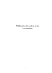
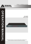
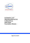
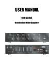
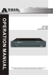
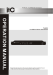
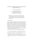
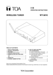
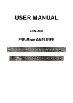
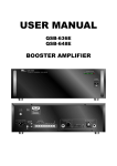
IP NETWORK PA SYSTEM
IP
T-6703
NETWORK AUDIO ADAPTER
OWNER'S MANUAL
Please follow the instructions in this manual to obtain the optimum results from this unit.
We also recommend that you keep this manual handy for future reference.
TABLE OF CONTENTS
1. SAFETY PRECAUTIONS............................................................................3
2. GENERAL DESCRIPTION..........................................................................5
3. FEATURES ...............................................................................................5
4. NOMENCLATURE AND FUNCTIONS
FRONT.....................................................................................................6
CONNECTION DRAWING................................... .......................................6
5. OPERATION .............................................................................................7
6. BLOCK DIAGRAM......................................................................................9
7. SPECIFICATIONS ...................................................................................10
2
1. SAFETY PRECAUTIONS
Be sure to read the instructions in this section carefully before use.
Make sure to observe the instructions in this manual as the conventions of safety symbols and messages
regarded as very important precautions are included.
We also recommend you keep this instruction manual handy for future reference.
Safety Symbol and Message Conventions
Safety symbols and messages described below are used in this manual to prevent bodily injury and property
damage which could result from mishandling. Before operating your product, read this manual first and
understand the safety symbols and messages so you are thoroughly aware of the potential safety
Indicates a potentially hazardous situation which, if mishandled, could
result in death or serious personal injury.
Indicates a potentially hazardous situation which, if mishandled, could
result in moderate or minor personal injury, and/or property damage.
When the Unit is in Use
When Installing the Unit
Should the following irregularity be found during
use, immediately switch off the power, disconnect
the power supply plug from the AC outlet and
contact your nearest ITC dealer. Make no further
attempt to operate the unit in this condition as this
may cause fire or electric shock.
If you detect smoke or a strange smell coming
from the unit.
If water or any metallic object gets into the unit
If the unit falls, or the unit case breaks
If the power supply cord is damaged (exposure of
the core, disconnection, etc.)
If it is malfunctioning (no tone sounds.)
Do not expose the unit to rain or an environment
where it may be splashed by water or other liquids,
as doing so may result in fire or electric shock.
Use the unit only with the voltage specified on the
unit. Using a voltage higher than that which is
specified may result in fire or electric shock.
Do not cut, kink, otherwise damage nor modify the
power supply cord. In addition, avoid using the
power cord in close proximity to heaters, and never
place heavy objects -- including the unit itself -- on
the power cord, as doing so may result in fire or
electric shock.
To prevent a fire or electric shock, never open nor
remove the unit case as there are high voltage
components inside the unit. Refer all servicing to
your nearest ITC dealer.
Be sure to replace the unit's terminal cover after
connection completion. Because high voltage is
applied to the speaker terminals, never touch these
terminals to avoid electric shock.
Do not place cups, bowls, or other containers of
liquid or metallic objects on top of the unit. If they
accidentally spill into the unit, this may cause a fire
or electric shock.
Be sure to ground to the safety ground (earth)
terminal to avoid electric shock. Never ground to a
gas pipe as a catastrophic disaster may result.
Do not insert nor drop metallic objects or
flammable materials in the ventilation slots of the
unit's cover, as this may result in fire or electric
shock.
Avoid installing or mounting the unit in unstable
locations, such as on a rickety table or a slanted
surface. Doing so may result in the unit falling
down, causing personal injury and/or property
damage.
3
SAFETY PRECAUTIONS
When the Unit is in Use
When Installing the Unit
Do not place heavy objects on the unit as this may
cause it to fall or break which may result in
personal injury and/or property damage. In
addition, the object itself may fall off and cause
injury and/or damage.
Never plug in nor remove the power supply plug
with wet hands, as doing so may cause electric
shock.
When unplugging the power supply cord, be sure
to grasp the power supply plug; never pull on the
cord itself. Operating the unit with a damaged
power supply cord may cause a fire or electric
shock.
Make sure that the volume control is set to
minimum position before power is switched on.
Loud noise produced at high volume when power is
switched on can impair hearing.
When moving the unit, be sure to remove its power
supply cord from the wall outlet. Moving the unit
with the power cord connected to the outlet may
cause damage to the power cord, resulting in fire or
electric shock. When removing the power cord, be
sure to hold its plug to pull.
Do not operate the unit for an extended period of
time with the sound distorting. This is an indication
of a malfunction, which in turn can cause heat to
generate and result in a fire.
Contact your ITC dealer as to the cleaning. If dust
is allowed to accumulate in the unit over a long
period of time, a fire or damage to the unit may
result.
Do not block the ventilation slots in the unit's cover.
Doing so may cause heat to build up inside the unit
and result in fire.
If dust accumulates on the power supply plug or in
the wall AC outlet, a fire may result. Clean it
periodically. In addition, insert the plug in the wall
outlet securely.
Avoid installing the unit in humid or dusty locations,
in locations exposed to the direct sunlight, near the
heaters, or in locations generating sooty smoke or
steam as doing otherwise may result in fire or
electric shock.
Switch off the power, and unplug the power supply
plug from the AC outlet for safety purposes when
cleaning or leaving the unit unused for 10 days or
more. Doing otherwise may cause a fire or electric
shock.
An all-pole mains switch with a contact separation of at least 3 mm in each pole shall be incorporated in
the electrical installation of the building.
Due to product upgrades, while some of the features and specification in the user manual does not
match the actual functions, sorry for any inconvenience and thanks for your kind understanding!
4
2. GENERAL DESCRIPTION
A key professional help network intercom terminal.
Suitable for indoor and outdoor, waterproof & explosion-proof; May initiate a key duty room intercom
communication.
3. FEATURES
1. Simple appearance, beautiful lines, high-grade brushed aluminum panel, durable, both in-wall
mount and surface mount design (with bottom box).
2. Embed PC technology, built-in DSP and high speed industrial chip to ensure start time less than
1 second.
3. A key to initiate a call to the target terminal, full-duplex communication, simple, fast connection.
4. Built-in high sensitivity microphone for long distance voice pick up, high reducibility tone.
5. Built-in a 5W full range monitor speaker of excellent voice restoration.
6. Built-in 10W class-D amplifier to power 4 & 10W speaker.
7. Hand free communication system.
8. Support 1 road short-circuit the input terminals, local electronic lock control linkage.
9. Support local emergency signal input.
10. A short circuit output, there are two kinds of trigger mode optional, and can be used for linkage
video or alarm indicator lamp.
11. Safe DC 11.5V~24.5V power adapter supplied.
12. Aluminum mounting box supplied with both surface mount and in-wall mount design.
13. Full aluminum body for weatherproof IP55 level and explosive-proof design.
14. Support WAN, LAN, Span gateway and cross router.
5
4. NOMENCLATURE AND FUCTIONS
Front panel
3
2
1. mic input, capable of paging or intercom.
2. The call button and call status indicator
pressing this key for paging, keyboard shortcut, one key for
paging or help.
1) indicator will be bright red if it is powered on normally;
2) indicator will be bright green if network connection is normal;
3) while call waiting, indicator a is on (flashing green light, 500ms/time);
4) when the intercom is linked, indicator a and b are on (flashing orange
light)
3. loud speaker output
while there is signal of one key for help or playing network bgm, the
speaker will sound.
1
Connection Diagram of the unit
Switch
PC
Network connection
terminals
- - - -
AMP OUT SHORT IN
-
-
SH
-
DC power input
Supporting power supply
of 24V
O
O U RT
T
PC
External speaker output all the way,
can external 10W speakers
Shortcircuit input, capable of connecting
electronic door locks circuit
-
Shortcircuit output, capable of
connecting local alarm circuit.
6
5. OPERATION
1). Connect the "TERMINAL" on this terminal and "TERMINAL" on the computer with a serial cable,
or convert into a usb port, click "start" button and then choose the "All programs", find "ITC intelligent
network broadcasting" and select "terminal configuration program 2.36", run the software program,
open Configuration dialog box to open the terminal in Figure 1, in the way for the serial port connection,
click "Search" dialog box appears as shown in Figure 2.
Figure 1
Figure 2
Queries (if terminal configuration) is completed, confirm the IP address , input the correct address
(such as: 192.168.1.100), the dialog box appears as shown in Figure 3. Confirm the crrect IP address,
click "input", write complete Recognized IP address, the dialog box appears as shown in Figure 4
(terminal configuration will automatically obtain the physical address of the MAC)
Figure 3
Figure 4
Click "OK", change the connection way to"network", and input the same IP address same as that
in the IP address bar in the Figure 5.click " Query ", when Inquiry is completed, the dialog box appears
as shown in Figure 6. The terminal configuration is successful.
Figure 5
Figure 6
7
OPERATION
2) IP network broadcasting system settings:
In the "Terminal Configuration", choose one terminal, and make the intercom code to be the call center
of T-6703,then when push the "call" button on the T-6703), the intercom between two terminals starts.
Figure 7
3) The network connection is normal, intercom panel indicator green, press the "talk back" after the
call button, can call the call center, after the call center answering, you can achieve two terminals
talk back between, such as unanswered or more than 20S unanswered, it will prompt no promise
to each other. agreed to talk on the phone, after the trumpet will be each other's voice.
4) When the call center calls on the machine, can appear have a call, press the "speaker" call button
response, can be connected on both ends of the dialogue between, if nobody reply, or more than
20S unanswered, it will be prompted to the other party no response, if after answering calls,
speakers will be each other's voice.
5) When there is audio input, after the call center answering, will appear in the call center speaker
back ground music, "AUX" if nobody reply, answering calls, the horn will be each other's voice.
6) When playing I P network radio music file, the speaker with "AMP OUT" background music will
have network in the output.
7) Connection good electronic door lock, when the door is opening or closing triggered when a short
circuit signal input to the terminal "SHORT IN".
8) Short circuit output function has a short circuit output trigger mode optional:
When press the "speaker" button on the panel, it can call the call center, at the same time also
can trigger short circuit output function, can be used for linkage video or other devices.
When playing I P web casts in the emergency alarm signal when the speaker with "AMP IN"
there will be alarm signal output, at the same time "SHORT OUT" there will be A short circuit
signal output.
8
SPEAKER
To the front circuitry
Board power supply network
ADAPTER
NETWORK DECODING
Ethernet port
6. BLOCK DIAGRAM
9
7. SPECIFICATIONS
Model
T-6703
Network Input
Standard Rj45 input
Protocol Support
TCP/IP,UDP,IGMP
(group broadcasting)
Audio Format
MP3/MP2
Sampling Rate
8K~48KHz
Transmit Speed
10/100M bps
Audo Mode
16-bit stereo CD sound level
Frequency Output
20Hz~16KHz
0.3%
T.H.D
S.N
>70dB
Aux Line Voltage Input
350mV Industrial standard screw terminals
Sources Voltage Output
1V Industrial standard screw terminals
Working Tempreture
5
Working Humidity
20%~80% Relative humidity, no condensing
Power Consumption
~40
20W
Power Supply
DC24V
Dimension
240X105X56mm
N.W
1Kg
10
INTELLCETIVE PUBLIC ADDRESS SYSTEM
VersionV0.2