1
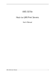
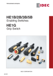
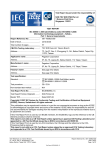
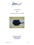
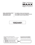
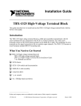
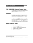
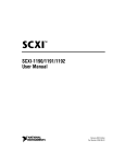
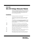
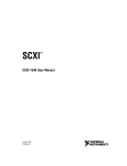
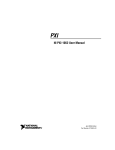
INSTALLATION GUIDE
TBX-1316 High-Voltage
Attenuator Terminal Block
This guide describes how to install and use the TBX-1316 high-voltage
attenuator terminal block with the following modules:
•
SCXI-1125 (recommended)
•
SCXI-1126
•
SCXI-1120/D
The TBX-1316 is a shielded metal enclosure with a built-in high-voltage
attenuator. You can use it to measure high-voltage signals of up to 1000 V
Category I and 600 V Category II.
Caution Do not use the TBX-1316 to connect to signals above 600 V Category II. Do not
use the TBX-1316 in Category III or IV applications. Do not connect to MAINS supply
circuits above 600 VAC.
The TBX-1316 has eight differential high-voltage input channels. Each
high-voltage input channel has three screw terminals—one each for input
plus, input minus, and chassis ground. For maximum safety, all the
chassis-ground terminals and the enclosure are connected. You can use
6 to 20 AWG signal wire in the screw terminals. Use an SH3232 shielded
cable to connect the TBX-1316 to the module.
Refer to the Read Me First: Safety and Radio-Interference document for definitions
of Categories and other safety information.
Note
Caution Do not use uninsulated input signal wires. All input signal wires must be
separated from each other and must have a minimum voltage rating of 1000 V for
Category I or 600 V for Category II and have a temperature rating of 90 °C.
Each input channel is formed by a pair of 200:1 fixed-attenuation-ratio
high-voltage resistor networks. The nominal inaccuracy of the attenuation
factor is < 1%, and the attenuation-ratio drift temperature coefficient is
< 20 ppm/°C.
Caution Install an application appropriate UL-Listed external breaker (disconnect) for
each input line.
A calibration EEPROM is built into the TBX-1316. When the TBX-1316
is used in conjunction with an SCXI-1125, the EEPROM stores calibration
constants. These constants provide software correction values that the
application development software uses to correct measurements for gain
error in the attenuation circuitry. The EEPROM is shipped with nominal
values. Refer to the Calibrating the TBX-1316 section for calibration
information.
Conventions
The following conventions are used in this guide:
»
The » symbol leads you through nested menu items and dialog box options
to a final action. The sequence File»Page Setup»Options directs you to
pull down the File menu, select the Page Setup item, and select Options
from the last dialog box.
This icon denotes a note, which alerts you to important information.
This icon denotes a caution, which advises you of precautions to take to
avoid injury, data loss, or a system crash. When this icon is marked on the
product, refer to the Read Me First: Safety and Radio-Frequency
Interference document, shipped with the product, for precautions to take.
When symbol is marked on a product it denotes a warning advising you to
take precautions to avoid electrical shock.
When symbol is marked on a product it denotes a component that may be
hot. Touching this component may result in bodily injury.
bold
Bold text denotes items that you must select or click in the software, such
as menu items and dialog box options. Bold text also denotes parameter
names.
italic
Italic text denotes variables, emphasis, a cross reference, or an introduction
to a key concept. This font also denotes text that is a placeholder for a word
or value that you must supply.
monospace
Text in this font denotes text or characters that you should enter from the
keyboard, sections of code, programming examples, and syntax examples.
This font is also used for the proper names of disk drives, paths, directories,
programs, subprograms, subroutines, device names, functions, operations,
variables, filenames, and extensions.
TBX-1316 High-Voltage Attenuator Terminal Block
2
ni.com
What You Need to Get Started
To install and use the TBX-1316, you need the following items:
❑ Hardware
–
TBX-1316 terminal block
–
One of the following modules:
–
–
–
•
SCXI-1125 (recommended)
•
SCXI-1126
•
SCXI-1120/D
One of the following chassis:
•
SCXI
•
PXI/SCXI combination
One of the following:
•
E/M Series DAQ PCI device
•
E/M Series DAQ PXI module
SH3232 shielded cable and cable adapter as required for your
application
❑ Documentation
–
Read Me First: Safety and Radio-Frequency Interference
–
DAQ Quick Start Guide
–
SCXI Quick Start Guide
–
TBX-1316 High-Voltage Attenuator Terminal Block Installation
Guide
–
One of the following user manuals (application-dependent):
–
•
SCXI-1125 User Manual
•
SCXI-1126 User Manual
•
SCXI-1120/D User Manual
SCXI or PXI/SCXI combination chassis user manual
❑ Tools
© National Instruments Corporation
–
Number 1 and 2 Phillips screwdriver
–
1/8 and 3/8 in. flathead screwdriver
–
Long nose pliers
–
Wire cutter
3
TBX-1316 High-Voltage Attenuator Terminal Block
–
Wire insulation stripper
–
Miscellaneous tools to permanently mount the enclosure
Installing the TBX-1316 Enclosure
Note Refer to the Read Me First: Safety and Radio-Frequency Interference document
before removing equipment covers or connecting or disconnecting any signal wires.
To install the TBX-1316 enclosure, complete the following steps:
1.
Install an application appropriate UL-Listed external breaker
(disconnect) for each input line as follows:
a.
Install the disconnect device(s) within close proximity of the
TBX-1316 and within easy reach of the operator.
b.
Mark this enclosure as a disconnect device.
The TBX-1316 is intended for mounting in a permanent location. NI recommends
installing the enclosure in a permanent location whenever possible.
Note
2.
Securely mount the enclosure to the building per the local safety codes.
If the enclosure is mounted on plaster board (drywall), mount the
enclosure using four #14 × 1 1/2 in. wood screws installed through the
four, 7.6 mm (0.3 in.) clearance mounting holes. Position the enclosure
so that all four screws are driven into wooden studs. Figure 1 shows the
clearance holes.
3.
While referring to Figure 2, unlock and open the enclosure door using
a 3/8 in. flathead screwdriver.
4.
While referring to Figure 3, complete the following steps to install the
protective earth (PE) ground wire.
The PE ground wire must comply with your local codes and be the same or larger
size AWG as the input signal wires.
Note
a.
Insert the PE ground wire through the PE ground strain-relief
collar.
b.
Install a UL-Listed uninsulated closed-ring terminal, suitable to
your application, on the end of the PE ground wire.
c.
Place the lock-washer over the ground-screw followed by the
PE ground terminal.
d.
Place the provided lock washer over the end of the ground screw.
The screw should now have a ring terminal between two lock
washers.
TBX-1316 High-Voltage Attenuator Terminal Block
4
ni.com
e.
Install the ground-screw/lock-washer into the enclosure, and
tighten it with a number 2 Phillips screwdriver.
f.
Tighten the PE ground strain-relief collar.
304.80 mm
[12.000 in]
323.85 mm
[12.750 in]
342.90 mm
[13.500 in]
1000 V CAT I
600 V CAT II
50 µA MAX per channel
9.53 mm
[0.375 in]
25.4 mm
[1.000 in]
203.20 mm
[8.000 in]
254.00 mm
[10.000 in]
Figure 1. TBX-1316 Enclosure Mounting Hole Spacing
© National Instruments Corporation
5
TBX-1316 High-Voltage Attenuator Terminal Block
Connecting the Signals
Note Be certain that the signal wires are of the appropriate AWG and voltage for your
application, and are rated for 90 °C.
To connect a signal to the TBX-1316, perform the following steps while
referring to Figures 2 and 3:
1.
Unlock and open the enclosure door using a 3/8 in. flathead
screwdriver.
Figure 2. Opening the TBX-1316
2.
Loosen the signal strain-relief collar.
3.
Run the signal wires through the strain-relief opening.
4.
Prepare the signal wire by stripping the insulation no more than
10 mm (0.39 in.).
When connecting the signals to the TBX-1316, follow the labeling on the
TBX-1316.
Note
TBX-1316 High-Voltage Attenuator Terminal Block
6
ni.com
5.
Connect chassis ground to the chassis-ground terminal strip.
6.
Connect the signal wires to the signal wire screw terminals by inserting
the stripped end of the wire fully into the terminal.
No bare wire should extend past the screw terminal. Exposed wire increases the
risk of short circuits and failures.
Caution
7.
Tighten the terminal screws to a torque of 1.2 to 1.5 N · m
(10.62 to 13.28 in. · lb).
8.
Tighten the signal strain-relief collar.
9.
Repeat steps 2 through 8 for each signal wire.
10. Close and lock the enclosure door.
11. Connect the TBX-1316 to the SCXI module front connector as
explained in the Connecting the Module section.
© National Instruments Corporation
7
TBX-1316 High-Voltage Attenuator Terminal Block
8
6
9
7
5
10
4
11
3
12
2
13
1
1
2
3
4
Protective Earth Ground
Strain-Relief Collar
Protective Earth Ground
Signal Cable Insulation
Signal Wire Insulation
5
6
7
8
Enclosure Door Lock
Enclosure Door
Enclosure Door Ground
SH3232 Shielded Cable
Connector
9
10
11
12
13
Protective Cover
Signal Wire Terminal Strip
Chassis Ground Terminal Strip
Enclosure
Signal Strain-Relief Collar
Figure 3. TBX-1316 Parts Locator Diagram
Connecting the Module
This section describes how to connect the TBX-1316 to an SCXI and
PXI/SCXI combination chassis.
Note
The illustrations show the SCXI chassis only.
TBX-1316 High-Voltage Attenuator Terminal Block
8
ni.com
To connect the TBX-1316 to an SCXI module front connector, perform the
following steps:
1.
If you have not already installed the E/M Series DAQ device, refer to
the DAQ Quick Start Guide for installation instructions.
2.
If you have not already installed the SCXI module, refer to the
SCXI Quick Start Guide for installation instructions.
3.
Power off the SCXI chassis.
4.
Do one of the following:
5.
•
Power off the computer that contains the E/M Series DAQ device,
and disconnect the device from the chassis.
•
Power off the PXI portion of the PXI/SCXI combination chassis,
and if used, remove the cable connecting the SCXI portion of the
chassis to E/M Series device.
Connect the TBX cable adapter to the appropriate SCXI module, and
secure it by tightening both thumbscrews, as shown in Figure 4.
4
5
4
3
2
1
2
ADDRESS
3
5
1
3
1
2
Mounting Screws and Ears
Cable
3
4
Thumbscrews
SCXI Chassis
5
TBX Cable Adapter
Figure 4. Connecting the Cable to the SCXI Module
© National Instruments Corporation
9
TBX-1316 High-Voltage Attenuator Terminal Block
6.
Connect one end of the cable assembly to the SH3232 shielded cable
connector on the TBX-1316, and secure the cable by tightening both
mounting screws, as shown in Figure 5.
1
2
1
1
Mounting Screws
2
Cable Assembly
Figure 5. Connecting the Cable to the TBX-1316
TBX-1316 High-Voltage Attenuator Terminal Block
10
ni.com
Connect the other end of the cable assembly to the SCXI module front
connector, and secure the cable by tightening the mounting screws.
Figure 6 shows the completed installation.
5
4
3
2
1
ADDRESS
7.
Figure 6. Completed Installation
8.
If necessary, reconnect the E/M Series DAQ device to the chassis.
9.
Refer to the SCXI Quick Start Guide to power on the SCXI chassis and
configure the system in software.
Calibrating the TBX-1316
NI recommends you perform an external calibration once a year.
You can download all available external calibration documents from
ni.com/calibration by clicking Manual Calibration Procedures.
© National Instruments Corporation
11
TBX-1316 High-Voltage Attenuator Terminal Block
Specifications
All specifications are typical at 25 °C unless otherwise specified.
Input Voltage Range
AC/DC ....................................................1000 V Category I
AC/DC ....................................................600 V Category II
Max input current per channel................50 µA
Impulse overvoltage ...............................4000 V
Bandwidth (3 dB)
SCXI-1125.......................................400 Hz
SCXI-1120.......................................400 Hz
Attenuation ratio .....................................200:1 (fixed)
Attenuation-ratio accuracy
Uncalibrated ....................................1% max
Attenuation-ratio temperature drift.........20 ppm/°C max
Differential input resistance....................44 MΩ typ
Physical
NI recommends that the TBX-1316 be permanently connected equipment
with an appropriate UL Listed external breaker for each line.
Enclosure protective earth (PE) ground must be installed.
Dimensions .............................................30.48 × 25.40 × 15.24 cm
(12 × 10 × 6 in.)
Weight ....................................................5.8 kg
(12.8 lb)
Strain-relief cable diameter.....................6 to 12 mm signals
(0.24 to 0.47 in.)
4 to 8 mm PE ground
(0.157 to 0.314 in.)
TBX-1316 High-Voltage Attenuator Terminal Block
12
ni.com
If your application cable diameter is smaller than what is listed above, replace the
supplied strain reliefs with the following strain reliefs or their equivalents. These strain
reliefs are not supplied with the TBX-1316.
Note
Strain-relief cable diameter .................... 5 to 9 mm signals
(0.197 to 0.354 in.)
SKINTOP # S2213
2 to 6 mm PE ground
(0.079 to 0.236 in.)
SKINTOP # S2209
Strain reliefs available............................ 8 signals
1 PE ground
Field wire
Diameter.......................................... 6 to 20 AWG
Temperature rating.......................... 90 °C
Connector type ....................................... Screw terminal
Environmental
Operating temperature............................ 0 to 55 °C
Storage temperature ............................... –20 to 70 °C
Humidity ................................................ 10 to 90% RH, noncondensing
Maximum altitude .................................. 2,000 m
Pollution Degree
(indoor use only) .................................... 2
Safety
The TBX-1316 is designed to meet the requirements of the following
standards of safety for electrical equipment for measurement, control,
and laboratory use:
•
IEC 61010-1, EN 61010-1
•
UL 61010-1
•
CAN/CSA-C22.2 No. 61010-1
Note For UL and other safety certifications, refer to the product label, or visit
ni.com/certification, search by model number or product line, and click the
appropriate link in the Certification column.
© National Instruments Corporation
13
TBX-1316 High-Voltage Attenuator Terminal Block
Electromagnetic Compatibility
Emissions................................................EN 55011 Class A at 10 m
FCC Part 15A above 1 GHz
Immunity ................................................EN 61326:1997 + A2:2001,
Table 1
EMC/EMI ...............................................CE, C-Tick, and FCC Part 15
(Class A) Compliant
Note
For EMC compliance, operate this device with shielded cabling.
CE Compliance
The TBX-1316 meets the essential requirements of applicable European
Directives, as amended for CE marking, as follows:
Low-Voltage Directive (safety)..............73/23/EEC
Electromagnetic Compatibility
Directive (EMC) .....................................89/336/EEC
Refer to the Declaration of Conformity (DoC) for this product for any additional
regulatory compliance information. To obtain the DoC for this product, visit
ni.com/certification, search by model number or product line, and click the
appropriate link in the Certification column.
Note
TBX-1316 High-Voltage Attenuator Terminal Block
14
ni.com
National Instruments, NI, ni.com, and LabVIEW are trademarks of National Instruments Corporation.
Refer to the Terms of Use section on ni.com/legal for more information about National
Instruments trademarks. Other product and company names mentioned herein are trademarks or trade
names of their respective companies. For patents covering National Instruments products, refer to the
appropriate location: Help»Patents in your software, the patents.txt file on your CD, or
ni.com/patents.
© 2004–2005 National Instruments Corporation. All rights reserved.
374061C-01
Apr05