1
hall_150015_ch07.qxd
8/25/06
3:16 PM
Page 157
7
Bootloaders
In this chapter
■
Role of a Bootloader
page 158
■
Bootloader Challenges
page 159
■
A Universal Bootloader: Das U-Boot
page 164
■
Porting U-Boot
page 172
■
Other Bootloaders
page 183
■
Chapter Summary
page 186
157
hall_150015_ch07.qxd
8/25/06
3:16 PM
158
Page 158
Chapter 7 • Bootloaders
revious chapters have made reference to and even provided examples of
bootloader operations. A critical component of an embedded system, the
bootloader provides the foundation from which the other system software is
spawned. This chapter starts by examining the bootloader’s role in a system. We
follow this with an introduction to some common features of bootloaders.
Armed with this background, we take a detailed look at a popular bootloader
used for embedded systems. We conclude this chapter by introducing a few of
the more popular bootloaders.
P
Numerous bootloaders are in use today. It would be impractical in the given
space to cover much detail on even the most popular ones. Therefore, we have
chosen to explain concepts and use examples based on one of the more popular
bootloaders in the open source community for PowerPC, MIPS, ARM, and other
architectures: the U-Boot bootloader.
7.1 Role of a Bootloader
When power is first applied to a processor board, many elements of hardware must
be initialized before even the simplest program can run. Each architecture and
processor has a set of predefined actions and configurations, which include fetching
some initialization code from an on-board storage device (usually Flash memory).
This early initialization code is part of the bootloader and is responsible for breathing life into the processor and related hardware components.
Most processors have a default address from which the first bytes of code are
fetched upon application of power and release of reset. Hardware designers use
this information to arrange the layout of Flash memory on the board and to select
which address range(s) the Flash memory responds to. This way, when power is first
applied, code is fetched from a well-known and predictable address, and software
control can be established.
The bootloader provides this early initialization code and is responsible for initializing the board so that other programs can run. This early initialization code is
almost always written in the processor’s native assembly language. This fact alone
presents many challenges, some of which we examine here.
Of course, after the bootloader has performed this basic processor and platform
initialization, its primary role becomes booting a full-blown operating system. It is
hall_150015_ch07.qxd
8/25/06
3:16 PM
Page 159
7.2 Bootloader Challenges
159
responsible for locating, loading, and passing execution to the primary operating
system. In addition, the bootloader might have advanced features, such as the capability to validate an OS image, the capability to upgrade itself or an OS image, and
the capability to choose from among several OS images based on a developerdefined policy. Unlike the traditional PC-BIOS model, when the OS takes control,
the bootloader is overwritten and ceases to exist.1
7.2 Bootloader Challenges
Even a simple “Hello World” program written in C requires significant hardware
and software resources. The application developer does not need to know or care
much about these details because the C runtime environment transparently provides this infrastructure. A bootloader developer has no such luxury. Every resource
that a bootloader requires must be carefully initialized and allocated before it is
used. One of the most visible examples of this is Dynamic Random Access Memory
(DRAM).
7.2.1 DRAM Controller
DRAM chips cannot be directly read from or written to like other microprocessor
bus resources. They require specialized hardware controllers to enable read and
write cycles. To further complicate matters, DRAM must be constantly refreshed or
the data contained within will be lost. Refresh is accomplished by sequentially reading each location in DRAM in a systematic manner and within the timing specifications set forth by the DRAM manufacturer. Modern DRAM chips support many
modes of operation, such as burst mode and dual data rate for high-performance
applications. It is the DRAM controller’s responsibility to configure DRAM, keep
it refreshed within the manufacturer’s timing specifications, and respond to the
various read and write commands from the processor.
Setting up a DRAM controller is the source of much frustration for the
newcomer to embedded development. It requires detailed knowledge of DRAM
architecture, the controller itself, the specific DRAM chips being used, and the overall hardware design. Though this is beyond the scope of this book, the interested
1
Some embedded designs protect the bootloader and provide callbacks to bootloader routines, but this is
almost never a good design approach. Linux is far more capable than bootloaders, so there is often little
point in doing so.
hall_150015_ch07.qxd
8/25/06
3:16 PM
160
Page 160
Chapter 7 • Bootloaders
reader can learn more about this important concept by referring to the references at
the end of this chapter. Appendix D, “SDRAM Interface Considerations,” provides
more background on this important topic.
Very little can happen in an embedded system until the DRAM controller and
DRAM itself have been properly initialized. One of the first things a bootloader
must do is to enable the memory subsystem. After it is initialized, memory can be
used as a resource. In fact, one of the first actions many bootloaders perform after
memory initialization is to copy themselves into DRAM for faster execution.
7.2.2 Flash Versus RAM
Another complexity inherent in bootloaders is that they are required to be stored in
nonvolatile storage but are usually loaded into RAM for execution. Again, the complexity arises from the level of resources available for the bootloader to rely on. In a
fully operational computer system running an operating system such as Linux, it is
relatively easy to compile a program and invoke it from nonvolatile storage. The
runtime libraries, operating system, and compiler work together to create the infrastructure necessary to load a program from nonvolatile storage into memory and
pass control to it. The aforementioned “Hello World” program is a perfect example. When compiled, it can be loaded into memory and executed simply by typing
the name of the executable (hello) on the command line (assuming, of course, that
the executable exists somewhere on your PATH).
This infrastructure does not exist when a bootloader gains control upon
power-on. Instead, the bootloader must create its own operational context and
move itself, if required, to a suitable location in RAM. Furthermore, additional
complexity is introduced by the requirement to execute from a read-only medium.
7.2.3 Image Complexity
As application developers, we do not need to concern ourselves with the layout of
a binary executable file when we develop applications for our favorite platform. The
compiler and binary utilities are preconfigured to build a binary executable image
containing the proper components needed for a given architecture. The linker
places startup (prologue) and shutdown (epilogue) code into the image. These
objects set up the proper execution context for your application, which typically
starts at main() in your application.
hall_150015_ch07.qxd
8/25/06
3:16 PM
Page 161
7.2 Bootloader Challenges
161
This is absolutely not the case with a typical bootloader. When the bootloader
gets control, there is no context or prior execution environment. In a typical system, there might not be any DRAM until the bootloader initializes the processor
and related hardware. Consider what this means. In a typical C function, any local
variables are stored on the stack, so a simple function like the one in Listing 7-1
is unusable.
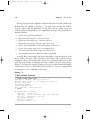
Listing 7-1
Simple C function
int setup_memory_controller(board_info_t *p)
{
unsigned int *dram_controller_register = p->dc_reg;
...
When a bootloader gains control on power-on, there is no stack and no stack
pointer. Therefore, a simple C function similar to Listing 7-1 will likely crash the
processor because the compiler will generate code to create and initialize the pointer
dram_controller_register on the stack, which does not yet exist. The bootloader must create this execution context before any C functions are called.
When the bootloader is compiled and linked, the developer must exercise complete control over how the image is constructed and linked. This is especially true
if the bootloader is to relocate itself from Flash to RAM. The compiler and linker
must be passed a handful of parameters defining the characteristics and layout of
the final executable image. Two primary characteristics conspire to add complexity
to the final binary executable image.
The first characteristic that presents complexity is the need to organize the
startup code in a format compatible with the processor’s boot sequence. The first
bytes of executable code must be at a predefined location in Flash, depending on
the processor and hardware architecture. For example, the AMCC PowerPC 405GP
processor seeks its first machine instructions from a hard-coded address of
0xFFFF_FFFC. Other processors use similar methods with different details. Some
processors are configurable at power-on to seek code from one of several predefined
locations, depending on hardware configuration signals.
How does a developer specify the layout of a binary image? The linker is passed
a linker description file, also called a linker command script. This special file can be
thought of as a recipe for constructing a binary executable image. Listing 7-2
contains a snippet from an existing linker description file in use in a popular bootloader, which we discuss shortly.
hall_150015_ch07.qxd
8/25/06
3:16 PM
Page 162
162
Chapter 7 • Bootloaders
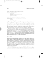
Listing 7-2
Linker Command Script—Reset Vector Placement
SECTIONS
{
.resetvec 0xFFFFFFFC :
{
*(.resetvec)
} = 0xffff
...
A complete description of linker command scripts syntax is beyond the scope of
this book. The interested reader is directed to the GNU LD manual referenced at
the end of this chapter. Looking at Listing 7-2, we see the beginning of the definition for the output section of the binary ELF image. It directs the linker to place
the section of code called .resetvec at a fixed address in the output image, starting at location 0xFFFF_FFFC. Furthermore, it specifies that the rest of this section
shall be filled with all ones (0xFFFF.) This is because an erased Flash memory array
contains all ones. This technique not only saves wear and tear on the Flash memory,
but it also significantly speeds up programming of that sector.
Listing 7-3 is the complete assembly language file from a recent U-Boot distribution that defines the .resetvec code section. It is contained in an assembly language file called .../cpu/ppc4xx/resetvec.S. Notice that this code section
cannot exceed 4 bytes in length in a machine with only 32 address bits. This is
because only a single instruction is defined in this section, no matter what configuration options are present.
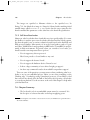
Listing 7-3
Source Definition of .resetvec
/* Copyright MontaVista Software Incorporated, 2000 */
#include <config.h>
.section .resetvec,"ax"
#if defined(CONFIG_440)
b _start_440
#else
#if defined(CONFIG_BOOT_PCI) && defined(CONFIG_MIP405)
b _start_pci
#else
b _start
#endif
#endif
hall_150015_ch07.qxd
8/25/06
3:16 PM
Page 163
7.2 Bootloader Challenges
163
This assembly language file is very easy to understand, even if you have no assembly language programming experience. Depending on the particular configuration
(as specified by the CONFIG_* macros), an unconditional branch instruction (b in
PowerPC assembler syntax) is generated to the appropriate start location in the
main body of code. This branch location is a 4-byte PowerPC instruction, and as
we saw in the snippet from the linker command script in Listing 7-2, this simple
branch instruction is placed in the absolute Flash address of 0xFFFF_FFFC in the
output image. As mentioned earlier, the PPC 405GP processor fetches its first
instruction from this hard-coded address. This is how the first sequence of code is
defined and provided by the developer for this particular architecture and processor
combination.
7.2.4 Execution Context
The other primary reason for bootloader image complexity is the lack of execution
context. When the sequence of instructions from Listing 7-3 starts executing (recall
that these are the first machine instructions after power-on), the resources available
to the running program are nearly zero. Default values designed into the hardware
ensure that fetches from Flash memory work properly and that the system clock has
some default values, but little else can be assumed.2 The reset state of each processor is usually well defined by the manufacturer, but the reset state of a board is
defined by the hardware designers.
Indeed, most processors have no DRAM available at startup for temporary storage of variables or, worse, for a stack that is required to use C program calling conventions. If you were forced to write a “Hello World” program with no DRAM and,
therefore, no stack, it would be quite different from the traditional “Hello World”
example.
This limitation places significant challenges on the initial body of code designed
to initialize the hardware. As a result, one of the first tasks the bootloader performs
on startup is to configure enough of the hardware to enable at least some minimal
amount of RAM. Some processors designed for embedded use have small amounts
of on-chip static RAM available. This is the case with the PPC 405GP we’ve been
discussing. When RAM is available, a stack can be allocated using part of that
2
The details differ, depending upon architecture, processor, and details of the hardware design.
hall_150015_ch07.qxd
8/25/06
3:16 PM
Page 164
164
Chapter 7 • Bootloaders
RAM, and a proper context can be constructed to run higher-level languages such
as C. This allows the rest of the processor and platform initialization to be written
in something other than assembly language.
7.3 A Universal Bootloader: Das U-Boot
Many open-source and commercial bootloaders are available, and many more oneof-a-kind home-grown designs are in widespread use today. Most of these have
some level of commonality of features. For example, all of them have some capability to load and execute other programs, particularly an operating system. Most
interact with the user through a serial port. Support for various networking subsystems (such as Ethernet) is less common but a very powerful feature.
Many bootloaders are specific to a particular architecture. The capability of a
bootloader to support a wide variety of architectures and processors can be an
important feature to larger development organizations. It is not uncommon for a
single development organization to have multiple processors spanning more than
one architecture. Investing in a single bootloader across multiple platforms ultimately results in lower development costs.
In this section, we study an existing bootloader that has become very popular in
the embedded Linux community. The official name for this bootloader is Das
U-Boot. It is maintained by Wolfgang Denk and hosted on SourceForge at http://
u-boot.sourceforge.net/. U-Boot has support for multiple architectures and has a
large following of embedded developers and hardware manufacturers who have
adopted it for use in their projects and have contributed to its development.
7.3.1 System Configuration: U-Boot
For a bootloader to be useful across many processors and architectures, some
method of configuring the bootloader is necessary. As with the Linux kernel itself,
configuration of a bootloader is done at compile time. This method significantly reduces the complexity of the bootloader, which, in itself, is an important
characteristic.
In the case of U-Boot, board-specific configuration is driven by a single header
file specific to the target platform, and a few soft links in the source tree that select
hall_150015_ch07.qxd
8/25/06
3:16 PM
Page 165
7.3 A Universal Bootloader: Das U-Boot
165
the correct subdirectories based on target board, architecture, and CPU. When configuring U-Boot for one of its supported platforms, issue this command:
$ make <platform>_config
Here, platform is one of the many platforms supported by U-Boot. These
platform-configuration targets are listed in the top level U-Boot makefile. For
example, to configure for the Spectrum Digital OSK, which contains a TI OMAP
5912 processor, issue this command:
$ make omap5912osk_config
This configures the U-Boot source tree with the appropriate soft links to select
ARM as the target architecture, the ARM926 core, and the 5912 OSK as the target
platform.
The next step in configuring U-Boot for this platform is to edit the configuration
file specific to this board. This file is found in the U-Boot ../include/configs
subdirectory and is called omap5912osk.h. The README file that comes with the
U-Boot distribution describes the details of configuration and is the best source for
this information.
Configuration of U-Boot is done using configuration variables defined in a
board-specific header file. Configuration variables have two forms. Configuration
options are selected using macros in the form of CONFIG_XXXX. Configuration
settings are selected using macros in the form of CFG_XXXX. In general, configuration options (CONFIG_XXX) are user configurable and enable specific U-Boot operational features. Configuration settings (CFG_XXX) are usually hardware specific and
require detailed knowledge of the underlying processor and/or hardware platform.
Board-specific U-Boot configuration is driven by a header file dedicated to that
specific platform that contains configuration options and settings appropriate
for the underlying platform. The U-Boot source tree includes a directory where
these board-specific configuration header files reside. They can be found in
.../include/configs from the top-level U-Boot source directory.
Numerous features and modes of operation can be selected by adding definitions
to the board-configuration file. Listing 7-4 contains a partial configuration header
file for a fictitious board based on the PPC 405GP processor.
hall_150015_ch07.qxd
8/25/06
3:16 PM
Page 166
Chapter 7 • Bootloaders
166
Listing 7-4
Partial U-Boot Board-Configuration Header File
#define CONFIG_405GP
#define CONFIG_4XX
/* Processor definition */
/* Sub-arch specification, 4xx family */
#define
#define
#define
...
#define
...
#define
33333333 /* PLL Frequency */
9600
/* Enable support for PCI */
CONFIG_SYS_CLK_FREQ
CONFIG_BAUDRATE
CONFIG_PCI
CONFIG_COMMANDS
(CONFIG_CMD_DFL | CFG_CMD_DHCP)
CFG_BASE_BAUD
691200
/* The following table includes the supported baudrates */
#define CFG_BAUDRATE_TABLE \
{1200, 2400, 4800, 9600, 19200, 38400, 57600, 115200, 230400}
#define CFG_LOAD_ADDR
0x100000
/* default load address */
...
/* Memory Bank 0 (Flash Bank 0) initialization */
#define CFG_EBC_PB0AP
0x9B015480
#define CFG_EBC_PB0CR
0xFFF18000
#define CFG_EBC_PB1AP
#define CFG_EBC_PB1CR
...
0x02815480
0xF0018000
Listing 7-4 gives an idea of how U-Boot itself is configured for a given board. An
actual board-configuration file can contain hundreds of lines similar to those found
here. In this example, you can see the definitions for the CPU, CPU family (4xx),
PLL clock frequency, serial port baud rate, and PCI support. We have included
examples of configuration variables (CONFIG_XXX) and configuration settings
(CFG_XXX). The last few lines are actual processor register values required to initialize the external bus controller for memory banks 0 and 1. You can see that these
values can come only from a detailed knowledge of the board and processor.
Many aspects of U-Boot can be configured using these mechanisms, including
what functionality will be compiled into U-Boot (support for DHCP, memory tests,
debugging support, and so on). This mechanism can be used to tell U-Boot how
much and what kind of memory is on a given board, and where that memory is
mapped. The interested reader can learn much more by looking at the U-Boot code
directly, especially the excellent README file.
hall_150015_ch07.qxd
8/25/06
3:16 PM
Page 167
7.3 A Universal Bootloader: Das U-Boot
167
7.3.2 U-Boot Command Sets
U-Boot supports more than 60 standard command sets that enable more than 150
unique commands using CFG_* macros. A command set is enabled in U-Boot
through the use of configuration setting (CFG_*) macros. For a complete list from
a recent U-Boot snapshot, consult Appendix B, “U-Boot Configurable
Commands.” Here are just a few, to give you an idea of the capabilities available:
Command Set
Commands
CFG_CMD_FLASH
Flash memory commands
CFG_CMD_MEMORY
Memory dump, fill, copy, compare, and so on
CFG_CMD_DHCP
DHCP Support
CFG_CMD_PING
Ping support
CFG_CMD_EXT2
EXT2 File system support
The following line of Listing 7-4 defines the commands enabled in a given
U-Boot configuration, as driven by the board-specific header file:
#define CONFIG_COMMANDS
(CONFIG_CMD_DFL | CFG_CMD_DHCP)
Instead of typing out each individual CFG_* macro in your own board-specific
configuration header, you can start from a default set of commands predefined in
the U-Boot source. The macro CONFIG_CMD_DFL defines this default set of commands. CONFIG_CMD_DFL specifies a list of default U-Boot command sets such as
tftpboot (boot an image from a tftpserver), bootm (boot an image from memory),
memory utilities such as md (display memory), and so on. To enable your specific
combination of commands, you can start with the default and add and subtract as
necessary. The example from Listing 7-4 adds the DHCP command set to the
default. You can subtract in a similar fashion:
#define CONFIG_COMMANDS
(CONFIG_CMD_DFL & ~CFG_CMD_NFS)
Take a look at any board-configuration header file in .../include/
for examples.
configs/
7.3.3 Network Operations
Many bootloaders include support for Ethernet interfaces. In a development environment, this is a huge time saver. Loading even a modest kernel image over a serial
hall_150015_ch07.qxd
8/25/06
3:16 PM
Page 168
Chapter 7 • Bootloaders
168
port can take minutes versus a few seconds over a 10Mbps Ethernet link.
Furthermore, serial links are more prone to errors from poorly behaved serial
terminals.
Some of the more important features to look for in a bootloader include support
for the BOOTP, DHCP, and TFTP protocols. For those unfamiliar with these,
BOOTP (Bootstrap Protocol) and DHCP (Dynamic Host Control Protocol) are
protocols that enable a target device with an Ethernet port to obtain an IP address
and other network-related configuration information from a central server. TFTP
(Trivial File Transfer Protocol) allows the target device to download files (such as a
Linux kernel image) from a TFTP server. References to these protocol specifications
are listed at the end of this chapter. Servers for these services are described in
Chapter 12”, “Embedded Development Environment.”
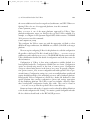
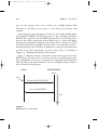
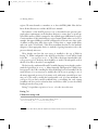
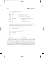
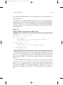
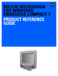
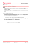
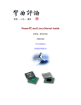
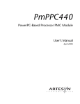
Figure 7-1 illustrates the flow of information between the target device and a
BOOTP server. The client (U-Boot, in this case) initiates a broadcast packet searching for a BOOTP server. The server responds with a reply packet that includes the
client’s IP address and other information. The most useful data includes a filename
used to download a kernel image.
U-Boot
BOOTP/DHCP
Server
Start
Broadcast: BOOTREQUEST
Unicast: BOOTREPLY
Time
FIGURE 7-1
BOOTP client/server handshake
hall_150015_ch07.qxd
8/25/06
3:16 PM
Page 169
7.3 A Universal Bootloader: Das U-Boot
169
In practice, dedicated BOOTP servers no longer exist as stand-alone servers.
DHCP servers included with your favorite Linux distribution also support BOOTP
protocol packets.
The DHCP protocol builds upon BOOTP. It can supply the target with a wide
variety of configuration information. In practice, the information exchange is often
limited by the target/bootloader DHCP client implementation. Listing 7-5 contains an example of a DHCP server configuration block identifying a single target
device. This is a snippet from a DHCP configuration file from the Fedora Core 2
DHCP implementation.
Listing 7-5
DHCP Target Specification
host coyote {
hardware ethernet 00:0e:0c:00:82:f8;
netmask 255.255.255.0;
fixed-address 192.168.1.21;
server-name 192.168.1.9;
filename "coyote-zImage";
option root-path "/home/chris/sandbox/coyote-target";
}
...
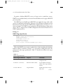
When this DHCP server receives a packet from a device matching the hardware
Ethernet address contained in Listing 7-5, it responds by sending that device the
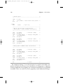
parameters in this target specification. Table 7-1 describes the fields in the target
specification.
TABLE 7-1
DHCP Target Parameters
DHCP Target Parameter
Purpose
Comments
host
Hostname
Symbolic label from DHCP
configuration file
hardware ethernet
Ethernet hardware address
Low-level Ethernet hardware
address of the target’s Ethernet
interface
fixed-address
Target IP address
The IP address that the target
will assume
(continues)
hall_150015_ch07.qxd
8/25/06
3:16 PM
Page 170
Chapter 7 • Bootloaders
170
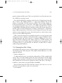
TABLE 7-1
(Continued)
DHCP Target Parameter
Purpose
Comments
netmask
Target netmask
The IP netmask that the target
will assume
server-name
TFTP server IP address
The IP address to which the
target will direct requests for
file transfers, root file system,
and so on
filename
TFTP filename
The filename that the bootloader can use to boot a secondary image (usually a Linux
kernel)
When the bootloader on the target board has completed the BOOTP or DHCP
exchange, the parameters described previously are used for further configuration.
For example, the bootloader uses the target IP address to bind its Ethernet port with
this IP address. The bootloader then uses the server-name field as a destination IP
address to request the file contained in the filename field, which, in most cases,
represents a Linux kernel image. Although this is the most common use, this same
scenario could be used to download and execute manufacturing test and diagnostics firmware.
It should be noted that the DHCP protocol supports many more parameters
than those detailed in Table 7-1. These are simply the more common parameters
you might encounter for embedded systems. See the DHCP specification referenced at the end of this chapter for complete details.
7.3.4 Storage Subsystems
Many bootloaders support the capability of booting images from a variety of nonvolatile storage devices in addition to the usual Flash memory. The difficulty in supporting these types of devices is the relative complexity in both hardware and software. To access data on a hard drive, for example, the bootloader must have device
driver code for the IDE controller interface, as well as knowledge of the underlying
hall_150015_ch07.qxd
8/25/06
3:16 PM
Page 171
7.3 A Universal Bootloader: Das U-Boot
171
partition scheme and file system. This is not trivial and is one of the tasks more suited to full-blown operating systems.
Even with the underlying complexity, methods exist for loading images from this
class of device. The simplest method is to support the hardware only. In this
scheme, no knowledge of the file system is assumed. The bootloader simply rawloads from absolute sectors on the device. This scheme can be used by dedicating
an unformatted partition from sector 0 on an IDE-compatible device (such as
CompactFlash) and loading the data found there without any structure imposed on
the data. This is an ideal configuration for loading a kernel image or other binary
image. Additional partitions on the device can be formatted for a given file system
and can contain complete file systems. After the kernel boots, device drivers can be
used to access the additional partitions.
U-Boot can load an image from a specified raw partition or from a partition with
a file system structure. Of course, the board must have a supported hardware device
(an IDE subsystem) and U-Boot must be so configured. Adding CFG_CMD_IDE to
the board-specific configuration file enables support for an IDE interface, and
adding CFG_CMD_BOOTD enables support for booting from a raw partition. If you
are porting U-Boot to a custom board, you will have to modify U-Boot to understand your particular hardware.
7.3.5 Booting from Disk: U-Boot
As described in the previous section, U-Boot supports several methods for booting
a kernel image from a disk subsystem. This simple command illustrates one of the
supported methods:
=> diskboot 0x400000 0:0
To understand this syntax, you must first understand how U-Boot numbers disk
devices. The 0:0 in this example specifies the device and partition. In this simple
example, U-Boot performs a raw binary load of the image found on the first IDE
device (IDE device 0) from the first partition found on this device. The image is
loaded into system memory at physical address 0x400000.
After the kernel image has been loaded into memory, the U-Boot bootm command (boot from memory) is used to boot the kernel:
=> bootm 0x400000
hall_150015_ch07.qxd
8/25/06
3:16 PM
Page 172
172
Chapter 7 • Bootloaders
7.4 Porting U-Boot
One of the reasons U-Boot has become so popular is the ease in which new platforms can be supported. Each board port must supply a subordinate makefile that
supplies board-specific definitions to the build process. These files are all given the
name config.mk and exist in the .../board/xxx subdirectory under the U-Boot
top-level source directory, where xxx specifies a particular board.
As of a recent U-Boot 1.1.4 snapshot, more than 240 different board configuration files are named config.mk under the .../boards subdirectory. In this same
U-Boot version, 29 different CPU configurations are supported (counted in the
same manner). Note that, in some cases, the CPU configuration covers a family of
chips, such as ppc4xx, which has support for several processors in the PowerPC 4xx
family. U-Boot supports a large variety of popular CPUs and CPU families in use
today, and a much larger collection of reference boards based on these processors.
If your board contains one of the supported CPUs, porting U-Boot is quite
straightforward. If you must add a new CPU, plan on significantly more effort. The
good news is that someone before you has probably done the bulk of the work.
Whether you are porting to a new CPU or a new board based on an existing CPU,
study the existing source code for specific guidance. Determine what CPU is closest to yours, and clone the functionality found in that CPU-specific directory.
Finally, modify the resulting sources to add the specific support for your new CPU’s
requirements.
7.4.1 EP405 U-Boot Port
The same logic applies to porting U-Boot to a new board. Let’s look at an example.
We will use the Embedded Planet EP405 board, which contains the AMCC
PowerPC 405GP processor. The particular board used for this example was provided courtesy of Embedded Planet and came with 64MB of SDRAM and 16MB
of on-board Flash. Numerous other devices complete the design.
The first step is to see how close we can come to an existing board. Many boards
in the U-Boot source tree support the 405GP processor. A quick grep of the boardconfiguration header files narrows the choices to those that support the 405GP
processor:
$ cd .../u-boot/include/configs$ grep -l CONFIG_405GP *
hall_150015_ch07.qxd
8/25/06
3:16 PM
Page 173
7.4 Porting U-Boot
173
In a recent U-Boot snapshot, 25 board configuration files are configured for
405GP. After examining a few, the AR405.h configuration is chosen as a baseline.
It contains support for the LXT971 Ethernet transceiver, which is also on the
EP405. The goal is to minimize any development work by borrowing from others
in the spirit of open source. Let’s tackle the easy steps first. Copy the boardconfiguration file to a new file with a name appropriate for your board. We’ll call
ours EP405.h. These commands are issued from the top-level U-Boot source tree.
$ cp .../include/configs/AR405.h .../include/configs/EP405.h
Then create the board-specific directory and make a copy of the AR405 board
files. We don’t know yet whether we need all of them. That step comes later. After
copying the files to your new board directory, edit the filenames appropriately for
your board name.
$ cd board
<<< from top level U-Boot source directory
$ mkdir ep405
$ cp esd/ar405/* ep405
Now comes the hard part. Jerry Van Baren, a developer and U-Boot contributor,
detailed a humorous though realistic process for porting U-Boot in an e-mail posting to the U-Boot mailing list. His complete process, documented in C, can be
found in the U-Boot README file. The following summarizes the hard part of the
porting process in Jerry’s style and spirit:
while (!running) {
do {
Add / modify source code
} until (compiles);
Debug;
...
}
Jerry’s process, as summarized here, is the simple truth. When you have selected
a baseline from which to port, you must add, delete, and modify source code until
it compiles, and then debug it until it is running without error! There is no magic
formula. Porting any bootloader to a new board requires knowledge of many areas
of hardware and software. Some of these disciplines, such as setting up SDRAM
controllers, are rather specialized and complex. Virtually all of this work involves a
detailed knowledge of the underlying hardware. The net result: Be prepared to
spend many entertaining hours poring over your processor’s hardware reference
manual, along with the data sheets of numerous other components that reside on
your board.
hall_150015_ch07.qxd
8/25/06
3:16 PM
Page 174
Chapter 7 • Bootloaders
174
7.4.2 U-Boot Makefile Configuration Target
Now that we have a code base to start from, we must make some modifications to
the top-level U-Boot makefile to add the configuration steps for our new board.
Upon examining this makefile, we find a section for configuring the U-Boot source
tree for the various supported boards. We now add support for our new one so we
can build it. Because we derived our board from the ESD AR405, we will use that
rule as the template for building our own. If you follow along in the U-Boot source
code, you will see that these rules are placed in the makefile in alphabetical order of
their configuration name. We shall be good open-source citizens and follow that
lead. We call our configuration target EP405_config, again in concert with the
U-Boot conventions.
EBONY_config:
unconfig
@./mkconfig $(@:_config=) ppc ppc4xx ebony
+EP405_config:
+
@./mkconfig
+
ERIC_config:
@./mkconfig
unconfig
$(@:_config=) ppc ppc4xx ep405
unconfig
$(@:_config=) ppc ppc4xx eric
Our new configuration rule has been inserted as shown in the three lines preceded with the + character (unified diff format).
Upon completing the steps just described, we have a U-Boot source tree that represents a starting point. It probably will not even compile cleanly, and that should
be our first step. At least the compiler can give us some guidance on where to start.
7.4.3 EP405 Processor Initialization
The first task that your new U-Boot port must do correctly is to initialize the
processor and the memory (DRAM) subsystems. After reset, the 405GP processor
core is designed to fetch instructions starting from 0xFFFF_FFFC. The core
attempts to execute the instructions found here. Because this is the top of the memory range, the instruction found here must be an unconditional branch instruction.
This processor core is also hard-coded to configure the upper 2MB memory
region so that it is accessible without programming the external bus controller, to
which Flash memory is usually attached. This forces the requirement to branch to
a location within this address space because the processor is incapable of addressing
memory anywhere else until our bootloader code initializes additional memory
hall_150015_ch07.qxd
8/25/06
3:16 PM
Page 175
7.4 Porting U-Boot
175
regions. We must branch to somewhere at or above 0xFFE0_0000. How did we
know all this? Because we read the 405GP user’s manual!
The behavior of the 405GP processor core, as described in the previous paragraph, places requirements on the hardware designer to ensure that, on power-up,
nonvolatile memory (Flash) is mapped to the required upper 2MB memory region.
Certain attributes of this initial memory region assume default values on reset. For
example, this upper 2MB region will be configured for 256 wait states, three cycles
of address-to-chip select delay, three cycles of chip select to output enable delay,
and seven cycles of hold time.3 This allows maximum freedom for the hardware
designer to select appropriate devices or methods of getting instruction code to the
processor directly after reset.
We’ve already seen how the reset vector is installed to the top of Flash in
Listing 7-2. When configured for the 405GP, our first lines of code will be found
in the file .../cpu/ppc4xx/start.S. The U-Boot developers intended this code
to be processor generic. In theory, there should be no need for board-specific code in
this file. You will see how this is accomplished.
We don’t need to understand PowerPC assembly language in any depth to understand the logical flow in start.S. Many frequently asked questions (FAQs) have
been posted to the U-Boot mailing list about modifying low-level assembly code. In
nearly all cases, it is not necessary to modify this code if you are porting to one of
the many supported processors. It is mature code, with many successful ports running on it. You need to modify the board-specific code (at a bare minimum) for
your port. If you find yourself troubleshooting or modifying the early startup
assembler code for a processor that has been around for a while, you are most likely
heading down the wrong road.
Listing 7-6 reproduces a portion of start.S for the 4xx architecture.
Listing 7-6
U-Boot 4xx startup code
...
#if defined(CONFIG_405GP) || defined(CONFIG_405CR) ||
defined(CONFIG_405) || defined(CONFIG_405EP)
/*--------------------------------- */
3
This data was taken directly from the 405GP user’s manual, referenced at the end of this chapter.
hall_150015_ch07.qxd
8/25/06
3:16 PM
Page 176
Chapter 7 • Bootloaders
176
/* Clear and set up some registers. */
/*--------------------------------- */
addi
r4,r0,0x0000
mtspr
sgr,r4
mtspr
dcwr,r4
mtesr
r4
/* clear Exception Syndrome Reg */
mttcr
r4
/* clear Timer Control Reg */
mtxer
r4
/* clear Fixed-Point Exception Reg */
mtevpr r4
/* clear Exception Vector Prefix Reg */
addi
r4,r0,0x1000
/* set ME bit (Machine Exceptions) */
oris
r4,r4,0x0002
/* set CE bit (Critical Exceptions) */
mtmsr
r4
/* change MSR */
addi
r4,r0,(0xFFFF-0x10000) /* set r4 to 0xFFFFFFFF (status in the */
/* dbsr is cleared by setting bits to 1) */
mtdbsr r4
/* clear/reset the dbsr */
/*---------------------------------- */
/* Invalidate I and D caches. Enable I cache for defined memory regions */
/* to speed things up. Leave the D cache disabled for now. It will be */
/* enabled/left disabled later based on user selected menu options. */
/* Be aware that the I cache may be disabled later based on the menu */
/* options as well. See miscLib/main.c. */
/*------------------------------------- */
bl
invalidate_icache
bl
invalidate_dcache
/*-------------------------------------- */
/* Enable two 128MB cachable regions.
*/
/*----------------------------------*/
addis
r4,r0,0x8000
addi
r4,r4,0x0001
mticcr r4
/* instruction cache */
isync
addis
addi
mtdccr
r4,r0,0x0000
r4,r4,0x0000
r4
/* data cache */
The first code to execute in start.S for the 405GP processor starts about a third
of the way into the source file, where a handful of processor registers are cleared or
set to sane initial values. The instruction and data caches are then invalidated, and
the instruction cache is enabled to speed up the initial load. Two 128MB cacheable
regions are set up, one at the high end of memory (the Flash region) and the other
at the bottom (normally the start of system DRAM). U-Boot eventually is copied
hall_150015_ch07.qxd
8/25/06
3:16 PM
Page 177
7.4 Porting U-Boot
177
to RAM in this region and executed from there. The reason for this is performance:
Raw reads from RAM are an order of magnitude (or more) faster than reads from
Flash. However, for the 4xx CPU, there is another subtle reason for enabling the
instruction cache, as we shall soon discover.
7.4.4 Board-Specific Initialization
The first opportunity for any board-specific initialization comes in
.../cpu/ppc4xx/start.S just after the cacheable regions have been initialized.
Here we find a call to an external assembler language routine called
ext_bus_cntlr_init.
bl ext_bus_cntlr_init
/* Board specific bus cntrl init */
This routine is defined in .../board/ep405/init.S, in the new board-specific
directory for our board. It provides a hook for very early hardware-based initialization. This is one of the files that has been customized for our EP405 platform. This
file contains the board-specific code to initialize the 405GP’s external bus controller
for our application. Listing 7-7 contains the meat of the functionality from this file.
This is the code that initializes the 405GP’s external bus controller.
Listing 7-7
External Bus Controller Initialization
.globl ext_bus_cntlr_init
ext_bus_cntlr_init:
mflr
r4
/* save link register
bl
..getAddr
..getAddr:
mflr
r3
/* get _this_ address
mtlr
r4
/* restore link register
addi
r4,0,14
/* prefetch 14 cache lines...
mtctr
r4
/* ...to fit this function
/* cache (8x14=112 instr)
..ebcloop:
icbt
r0,r3
/* prefetch cache line for [r3]
addi
r3,r3,32
/* move to next cache line
bdnz
..ebcloop
/* continue for 14 cache lines
*/
*/
*/
/*--------------------------------------------------/* Delay to ensure all accesses to ROM are complete
/* before changing bank 0 timings
/* 200usec should be enough.
/* 200,000,000 (cycles/sec) X .000200 (sec) =
*/
*/
*/
*/
*/
*/
*/
*/
*/
*/
*/
hall_150015_ch07.qxd
8/25/06
3:16 PM
Page 178
Chapter 7 • Bootloaders
178
/* 0x9C40 cycles
*/
/*--------------------------------------------------- */
addis
ori
mtctr
..spinlp:
bdnz
r3,0,0x0
r3,r3,0xA000 /* ensure 200usec have passed t */
r3
..spinlp
/* spin loop
*/
/*----------------------------------------------------*/
/* Now do the real work of this function
*/
/* Memory Bank 0 (Flash and SRAM) initialization
*/
/*----------------------------------------------------*/
addi
mtdcr
addis
ori
mtdcr
r4,0,pb0ap
ebccfga,r4
r4,0,EBC0_B0AP@h
r4,r4,EBC0_B0AP@l
ebccfgd,r4
addi
mtdcr
addis
ori
mtdcr
r4,0,pb0cr
ebccfga,r4
r4,0,EBC0_B0CR@h
r4,r4,EBC0_B0CR@l
ebccfgd,r4
/* *ebccfga = pb0ap;
/* *ebccfgd = EBC0_B0AP;
/* *ebccfga = pb0cr;
/* *ebccfgd = EBC0_B0CR;
*/
*/
*/
*/
/*----------------------------------------------------*/
/* Memory Bank 4 (NVRAM & BCSR) initialization
*/
/*----------------------------------------------------*/
addi
mtdcr
addis
ori
mtdcr
r4,0,pb4ap
ebccfga,r4
r4,0,EBC0_B4AP@h
r4,r4,EBC0_B4AP@l
ebccfgd,r4
addi
mtdcr
addis
ori
mtdcr
r4,0,pb4cr
ebccfga,r4
r4,0,EBC0_B4CR@h
r4,r4,EBC0_B4CR@l
ebccfgd,r4
blr
/* *ebccfga = pb4ap;
/* *ebccfgd = EBC0_B4AP;
/* *ebccfga = pb4cr;
/* *ebccfgd = EBC0_B4CR;
/* return
*/
*/
*/
*/
*/
The example in Listing 7-7 was chosen because it is typical of the subtle complexities involved in low-level processor initialization. It is important to realize the
context in which this code is running. It is executing from Flash, before any DRAM
is available. There is no stack. This code is preparing to make fundamental changes
hall_150015_ch07.qxd
8/25/06
3:16 PM
7.4 Porting U-Boot
Page 179
179
to the controller that governs access to the very Flash it is executing from. It is well
documented for this particular processor that executing code from Flash while
modifying the external bus controller to which the Flash is attached can lead to
errant reads and a resulting processor crash.
The solution is shown in this assembly language routine. Starting at the label
..getAddr, and for the next seven assembly language instructions, the code essentially prefetches itself into the instruction cache, using the icbt instruction. When
the entire subroutine has been successfully read into the instruction cache, it can
proceed to make the required changes to the external bus controller without fear of
a crash because it is executing directly from the internal instruction cache. Subtle,
but clever! This is followed by a short delay to make sure all the requested i-cache
reads have completed.
When the prefetch and delay have completed, the code proceeds to configure
Memory Bank 0 and Memory Bank 4 appropriately for our board. The values come
from a detailed knowledge of the underlying components and their interconnection
on the board. The interested reader can consult the “Suggestions for Additional
Reading” at the end of the chapter for all the details of PowerPC assembler and the
405GP processor from which this example was derived.
Consider making a change to this code without a complete understanding of
what is happening here. Perhaps you added a few lines and increased its size beyond
the range that was prefetched into the cache. It would likely crash (worse, it might
crash only sometimes), but stepping through this code with a debugger would not
yield a single clue as to why.
The next opportunity for board-specific initialization comes after a temporary
stack has been allocated from the processor’s data cache. This is the branch to initialize the SDRAM controller around line 727 of .../cpu/ppc4xx/start.S:
bl sdram_init
The execution context now includes a stack pointer and some temporary memory for local data storage—that is, a partial C context, allowing the developer to use
C for the relatively complex task of setting up the system SDRAM controller and
other initialization tasks. In our EP405 port, the sdram_init() code resides in
.../board/ep405/ep405.c and was customized for this particular board and
DRAM configuration. Because this board does not use a commercially available
memory SIMM, it is not possible to determine the configuration of the DRAM
hall_150015_ch07.qxd
8/25/06
3:16 PM
180
Page 180
Chapter 7 • Bootloaders
dynamically, like so many other boards supported by U-Boot. It is hard-coded in
sdram_init.
Many off-the-shelf memory DDR modules have a SPD (Serial Presence Detect)
PROM containing parameters defining the memory module. These parameters can
be read under program control via I2C and can be used as input to determine
proper parameters for the memory controller. U-Boot has support for this technique but might need to be modified to work with your specific board. Many examples of its use can be found in the U-Boot source code. The configuration option
CONFIG_SPD_EEPROM enables this feature. You can grep for this option to find
examples of its use.
7.4.5 Porting Summary
By now, you can appreciate some of the difficulties of porting a bootloader to a
hardware platform. There is simply no substitute for a detailed knowledge of the
underlying hardware. Of course, we’d like to minimize our investment in time
required for this task. After all, we usually are not paid based on how well we understand every hardware detail of a given processor, but rather on our ability to deliver
a working solution in a timely manner. Indeed, this is one of the primary reasons
open source has flourished. We just saw how easy it was to port U-Boot to a new
hardware platform—not because we’re world-class experts on the processor, but
because many before us have done the bulk of the hard work already.
Listing 7-8 is the complete list of new or modified files that complete the basic
EP405 port for U-Boot. Of course, if there had been new hardware devices for
which no support exists in U-Boot, or if we were porting to a new CPU that is not
yet supported in U-Boot, this would have been a much more significant effort. The
point to be made here, at the risk of sounding redundant, is that there is simply no
substitute for a detailed knowledge of both the hardware (CPU and subsystems)
and the underlying software (U-Boot) to complete a port successfully in a reasonable time frame. If you start the project from that frame of mind, you will have a
successful outcome.
hall_150015_ch07.qxd
8/25/06
3:16 PM
Page 181
7.4 Porting U-Boot
181
Listing 7-8
New or Changed Files for U-Boot EP405 Port
$ diff -purN u-boot u-boot-ep405/ | grep +++
+++ u-boot-ep405/board/ep405/config.mk
+++ u-boot-ep405/board/ep405/ep405.c
+++ u-boot-ep405/board/ep405/ep405.h
+++ u-boot-ep405/board/ep405/flash.c
+++ u-boot-ep405/board/ep405/init.S
+++ u-boot-ep405/board/ep405/Makefile
+++ u-boot-ep405/board/ep405/u-boot.lds
+++ u-boot-ep405/include/config.h
+++ u-boot-ep405/include/config.mk
+++ u-boot-ep405/include/configs/EP405.h
+++ u-boot-ep405/include/ppc405.h
+++ u-boot-ep405/Makefile
Recall that we derived all the files in the .../board/ep405 directory from another
directory. Indeed, we didn’t create any files from scratch for this port. We borrowed
from the work of others and customized where necessary to achieve our goals.
7.4.6 U-Boot Image Format
Now that we have a working bootloader for our EP405 board, we can load and run
programs on it. Ideally, we want to run an operating system such as Linux. To do
this, we need to understand the image format that U-Boot requires. U-Boot expects
a small header on the image file that identifies several attributes of the image.
U-Boot uses the mkimage tool (part of the U-Boot source code) to build this image
header.
Recent Linux kernel distributions have built-in support for building images
directly bootable by U-Boot. Both the ARM and PPC branches of the kernel source
tree have support for a target called uImage. Let’s look at the PPC case. The
following snippet from the Linux kernel PPC makefile .../arch/
ppc/boot/images/Makefile contains the rule for building the U-Boot target
called uImage:
quiet_cmd_uimage = UIMAGE $@
cmd_uimage = $(CONFIG_SHELL) $(MKIMAGE) -A ppc \
-O linux -T kernel -C gzip -a 00000000 -e 00000000 \
-n 'Linux-$(KERNELRELEASE)' -d $< $@
hall_150015_ch07.qxd
8/25/06
3:16 PM
Page 182
Chapter 7 • Bootloaders
182
Ignoring the syntactical complexity, understand that this rule calls a shell script
identified by the variable $(MKIMAGE). The shell script executes the U-Boot
mkimage utility with the parameters shown. The mkimage utility creates the
U-Boot header and prepends it to the supplied kernel image. The parameters are
defined as follows:
-C
Specifies the target image architecture
Species the target image OS—in this case, Linux
Specifies the target image type—a kernel, in this case
Specifies the target image compression type—here, gzip
-a
Sets the U-Boot loadaddress to the value specified—in this case, 0
-e
Sets the U-Boot image entry point to the supplied value
A text field used to identify the image to the human user
The executable image file to which the header is prepended
-A
-O
-T
-n
-d
Several U-Boot commands use this header data both to verify the integrity of the
image (U-Boot also puts a CRC signature in the header) and to instruct various
commands what to do with the image. U-Boot has a command called iminfo that
reads the image header and displays the image attributes from the target image.
Listing 7-9 contains the results of loading a uImage (bootable Linux kernel image
formatted for U-Boot) to the EP405 board via U-Boot’s tftpboot command and
executing the iminfo command on the image.
Listing 7-9
U-Boot iminfo Command
=> tftpboot 400000 uImage-ep405
ENET Speed is 100 Mbps - FULL duplex connection
TFTP from server 192.168.1.9; our IP address is 192.168.1.33
Filename 'uImage-ep405'.
Load address: 0x400000
Loading: ########## done
Bytes transferred = 891228 (d995c hex)
=> iminfo
## Checking Image at 00400000 ...
Image Name:
Linux-2.6.11.6
Image Type:
PowerPC Linux Kernel Image (gzip compressed)
Data Size:
891164 Bytes = 870.3 kB
Load Address: 00000000
Entry Point: 00000000
Verifying Checksum ... OK
=>
hall_150015_ch07.qxd
8/25/06
3:16 PM
Page 183
7.5 Other Bootloaders
183
7.5 Other Bootloaders
Here we introduce the more popular bootloaders, describe where they might be
used, and give a summary of their features. This is not intended to be a thorough
tutorial because to do so would require a book of its own. The interested reader can
consult the “Suggestions for Additional Reading” at the end of this chapter for
further study.
7.5.1 Lilo
The Linux Loader, or Lilo, was widely used in commercial Linux distributions for
desktop PC platforms; as such, it has its roots in the Intel x86/IA32 architecture.
Lilo has several components. It has a primary bootstrap program that lives on the
first sector of a bootable disk drive.4 The primary loader is limited to a disk sector
size, usually 512 bytes. Therefore, its primary purpose is simply to load and pass
control to a secondary loader. The secondary loader can span multiple partitions
and does most of the work of the bootloader.
Lilo is driven by a configuration file and utility that is part of the lilo executable. This configuration file can be read or written to only under control of the
host operating system. That is, the configuration file is not referenced by the early
boot code in either the primary or secondary loaders. Entries in the configuration
file are read and processed by the lilo configuration utility during system installation or administration. Listing 7-10 is an example of a simple lilo.conf configuration file describing a typical dual-boot Linux and Windows installation.
Listing 7-10
Example Lilo Configuration: lilo.conf
# This is the global lilo configuration section
# These settings apply to all the "image" sections
boot = /dev/hda
timeout=50
default=linux
4
This is mostly for historical reasons. From the early days of PCs, BIOS programs loaded only the first
sector of a disk drive and passed control to it.
hall_150015_ch07.qxd
8/25/06
3:16 PM
Page 184
184
Chapter 7 • Bootloaders
# This describes the primary kernel boot image
# Lilo will display it with the label 'linux'
image=/boot/myLinux-2.6.11.1
label=linux
initrd=/boot/myInitrd-2.6.11.1.img
read-only
append="root=LABEL=/"
# This is the second OS in a dual-boot configuration
# This entry will boot a secondary image from /dev/hda1
other=/dev/hda1
optional
label=that_other_os
This configuration file instructs the Lilo configuration utility to use the master
boot record of the first hard drive (/dev/hda). It contains a delay instruction to
wait for the user to press a key before the timeout (5 seconds, in this case). This
gives the system operator the choice to select from a list of OS images to boot. If
the system operator presses the Tab key before the timeout, Lilo presents a list to
choose from. Lilo uses the label tag as the text to display for each image.
The images are defined with the image tag in the configuration file. In the example presented in Listing 7-10, the primary (default) image is a Linux kernel image
with a file name of myLinux-2.6.11.1. Lilo loads this image from the hard drive.
It then loads a second file to be used as an initial ramdisk. This is the file
myInitrd-2.6.11.1.img. Lilo constructs a kernel command line containing the
string "root=LABEL=/" and passes this to the Linux kernel upon execution. This
instructs Linux where to get its root file system after boot.
7.5.2 GRUB
Many current commercial Linux distributions now ship with the GRUB bootloader. GRUB, or GRand Unified Bootloader, is a GNU project. It has many
enhanced features not found in Lilo. The biggest difference between GRUB and
Lilo is GRUB’s capability to understand file systems and kernel image formats.
Furthermore, GRUB can read and modify its configuration at boot time. GRUB
also supports booting across a network, which can be a tremendous asset in an
embedded environment. GRUB offers a command line interface at boot time to
modify the boot configuration.
Like Lilo, GRUB is driven by a configuration file. Unlike Lilo’s static configuration however, the GRUB bootloader reads this configuration at boot time. This
hall_150015_ch07.qxd
8/25/06
3:16 PM
Page 185
7.5 Other Bootloaders
185
means that the configured behavior can be modified at boot time for different system configurations.
Listing 7-11 is an example GRUB configuration file. This is the configuration
file from the PC on which this manuscript is being written. The GRUB configuration file is called grub.conf and is usually placed in a small partition dedicated to
storing boot images. On the machine from which this example is taken, that directory is called /boot.
Listing 7-11
Example GRUB Configuration File: grub.conf
default=0
timeout=3
splashimage=(hd0,1)/grub/splash.xpm.gz
title Fedora Core 2 (2.6.9)
root (hd0,1)
kernel /bzImage-2.6.9 ro root=LABEL=/ rhgb proto=imps quiet
initrd /initrd-2.6.9.img
title Fedora Core (2.6.5-1.358)
root (hd0,1)
kernel /vmlinuz-2.6.5-1.358 ro root=LABEL=/ rhgb quiet
title That Other OS
rootnoverify (hd0,0)
chainloader +1
GRUB first presents the user with a list of images that are available to boot. The
title entries from Listing 7-11 are the image names presented to the user.
The default tag specifies which image to boot if no keys have been pressed in the
timeout period, which is 3 seconds in this example. Images are counted starting
from zero.
Unlike Lilo, GRUB can actually read a file system on a given partition to load an
image from. The root tag specifies the root partition from which all filenames in
the grub.conf configuration file are rooted. In this example configuration, the
root is partition number 1 on the first hard disk drive, specified as root(hd0,1).
Partitions are numbered from zero; this is the second partition on the first hard
disk.
hall_150015_ch07.qxd
8/25/06
3:16 PM
Page 186
Chapter 7 • Bootloaders
186
The images are specified as filenames relative to the specified root. In
Listing 7-11, the default boot image is a Linux 2.6.9 kernel with a matching initial
ramdisk image called initrd-2.6.9.img. Notice that the GRUB syntax has the
kernel command line parameters on the same line as the kernel file specification.
7.5.3 Still More Bootloaders
Numerous other bootloaders have found their way into specific niches. For example, Redboot is another open-source bootloader that Intel and the XScale community have adopted for use on various evaluation boards based on the Intel IXP and
PXA processor families. Micromonitor is in use by board vendors such as Cogent
and others. YAMON has found popularity in MIPs circles.5 LinuxBIOS is used primarily in X86 environments. In general, when you consider a boot loader, you
should consider some important factors up front:
• Does it support my chosen processor?
• Has it been ported to a board similar to my own?
• Does it support the features I need?
• Does it support the hardware devices I intend to use?
• Is there a large community of users where I might get support?
• Are there any commercial vendors from which I can purchase support?
These are some of the questions you must answer when considering what bootloader to use in your embedded project. Unless you are doing something on the
“bleeding edge” of technology using a brand-new processor, you are likely to find
that someone has already done the bulk of the hard work in porting a bootloader
to your chosen platform. Use the resources at the end of this chapter to help make
your final decisions.
7.6 Chapter Summary
• The bootloader’s role in an embedded system cannot be overstated. It is
the first piece of software that takes control upon applying power.
5
In an acknowledgment of the number of bootloaders in existence, the YAMON user’s guide bills itself as
Yet Another MONitor.
hall_150015_ch07.qxd
8/25/06
3:16 PM
Page 187
7.6 Chapter Summary
187
• This chapter examined the role of the bootloader and discovered the
limited execution context in which a bootloader must exist.
• Das U-Boot has become a popular universal bootloader for many processor architectures. It supports a large number of processors, reference hardware platforms, and custom boards.
• U-Boot is configured using a series of configuration variables in a boardspecific header file. Appendix B contains a list of all the standard U-Boot
command sets supported in a recent U-Boot release.
• Porting U-Boot to a new board based on a supported processor is relatively
straightforward. In this chapter, we walked through the steps of a typical
port to a board with similar support in U-Boot.
• There is no substitute for detailed knowledge of your processor and
hardware platform when bootloader modification or porting must be
accomplished.
• We briefly introduced additional bootloaders in use today so you can
make an informed choice for your particular requirements.
7.6.1 Suggestions for Additional Reading
Application Note: Introduction to Synchronous DRAM
Maxwell Technologies
www.maxwell.com/pdf/me/app_notes/Intro_to_SDRAM.pdf
Using LD, the GNU linker
Free Software Foundation
www.gnu.org/software/binutils/manual/ld-2.9.1/ld.html
The DENX U-Boot and Linux Guide (DLUG) for TQM8xxL
Wolfgang Denx et al., Denx Software Engineering
www.denx.de/twiki/bin/view/DULG/Manual
RFC 793, “Trivial File Transfer Protocol”
The Internet Engineering Task Force
www.ietf.org/rfc/rfc793.txt
hall_150015_ch07.qxd
8/25/06
3:16 PM
Page 188
Chapter 7 • Bootloaders
188
RFC 951, “Bootstrap Protocol”
The Internet Engineering Task Force
www.ietf.org/rfc/rfc951.txt
RFC 1531, “Dynamic Host Control Protocol”
The Internet Engineering Task Force
www.ietf.org/rfc/rfc1531.txt
PowerPC 405GP Embedded Processor user’s manual
International Business Machines, Inc.
Programming Environments Manual for 32-bit Implementations
of the PowerPC Architecture
Freescale Semiconductor, Inc.
Lilo Bootloader
www.tldp.org/HOWTO/LILO.html
GRUB Bootloader
www.gnu.org/software/grub/