1
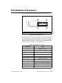
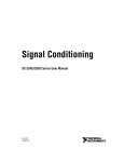
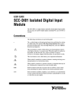
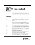
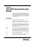
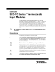
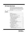
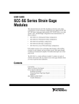
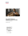
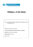
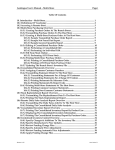
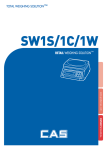
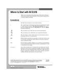
USER GUIDE
SCC-A10 Voltage Attenuator Module
The SCC-A10 voltage attenuator module accepts up to two voltage sources
of 60 V maximum amplitude and attenuates each voltage by a factor of 10.
A differential instrumentation amplifier buffers each input signal. The
SCC-A10 contains circuitry capable of protecting E/M Series DAQ
devices for input signals up to 60 VDC.
Conventions
The following conventions are used in this guide:
<>
Angle brackets that contain numbers separated by an ellipsis represent
a range of values associated with a bit or signal name—for example,
AO <3..0>.
»
The » symbol leads you through nested menu items and dialog box options
to a final action. The sequence File»Page Setup»Options directs you to
pull down the File menu, select the Page Setup item, and select Options
from the last dialog box.
This icon denotes a note, which alerts you to important information.
This icon denotes a caution, which advises you of precautions to take to
avoid injury, data loss, or a system crash. When this symbol is marked on
the product, refer to the Read Me First: Safety and Radio-Frequency
Interference document, shipped with the product, for precautions to take.
When symbol is marked on a product, it denotes a warning advising you to
take precautions to avoid electrical shock.
When symbol is marked on a product, it denotes a component that may be
hot. Touching this component may result in bodily injury.
bold
Bold text denotes items that you must select in software, such as menu
items and dialog box options. Bold text also denotes parameter names.
italic
Italic text denotes variables, emphasis, a cross reference, or an introduction
to a key concept. Italic text also denotes text that is a placeholder for a word
or value that you must supply.
monospace
Text in this font denotes text or characters that you should enter from the
keyboard, sections of code, programming examples, and syntax examples.
This font is also used for the proper names of disk drives, paths, directories,
programs, subprograms, subroutines, device names, functions, operations,
variables, filenames, and extensions.
SC-2345
SC-2345 refers to both the SC-2345 connector block and the SC-2345
configurable connector.
SCC
SCC refers to any SCC Series signal conditioning module.
What You Need to Get Started
To set up and use the SCC-A10, you need the following items:
❑ Hardware
–
SCC-68
or
–
SC-2345/2350 with one of the following:
•
SCC-PWR01
•
SCC-PWR02 and the PS01 power supply
•
SCC-PWR03 (requires a 7 to 42 VDC power supply, not
included)
–
One or more SCC-A10
–
68-pin E/M Series DAQ device
–
68-pin cable
–
Quick Reference Label
❑ Software
–
The latest version of NI-DAQmx
❑ Documentation
–
SCC-A10 Voltage Attenuator Module User Guide
–
SCC-68 User Guide
or
–
SC-2345/2350 User Manual
–
SCC Quick Start Guide
SCC-A10 Voltage Attenuator Module User Guide
2
ni.com
–
Read Me First: Safety and Radio-Frequency Interference
–
Documentation for your hardware
–
Documentation for your software
❑ Tools
–
1/8 in. flathead screwdriver
–
Numbers 1 and 2 Phillips screwdrivers
–
Wire insulation stripper
Software scaling of measurements is not supported on the Macintosh operating
system. Refer to the SCC-A10 Module Pin Assignments section.
Note
You can download NI documents from ni.com/manuals. To download
the latest version of NI-DAQmx, click Download Software at ni.com.
Device Specific Information
For general SCC module installation and signal connection information, and
information about the SC-2345/2350 and SC-68, refer to the SCC Quick Start Guide,
available for download at ni.com/manuals.
Note
Installing the Module
Caution Refer to the Read Me First: Safety and Radio-Frequency Interference document
before removing equipment covers or connecting/disconnecting any signal wires.
You can plug the SCC-A10 into any analog input socket on the
SC-2345/2350 or SCC-68. The socket you choose determines which E/M
Series DAQ device channels receive the SCC-A10 signals, as explained in
the SCC Quick Start Guide.
For single-stage input conditioning, plug the SCC-A10 into any slot of the
SC-68, or any socket of the SC-2345/2350 J(X+1), where X is 0 to 7.
Connect the input-signal wires to the module as described in the SCC Quick
Start Guide.
If you use the SCC-A10 in a dual-stage configuration in an SC-2345, the
SCC-A10 must be the first-stage module. Plug it into any socket J(X+9) and
plug the second-stage SCC into socket J(X+1), where X is 0 to 7. Connect
the input-signal wires to the SCC-A10 as described in the SCC Quick Start
Guide. The SC-2345 connects the output signals of the SCC-A10 to the
© National Instruments Corporation
3
SCC-A10 Voltage Attenuator Module User Guide
inputs of the second-stage SCC. An example of dual-stage conditioning is
an SCC-A10 followed by a lowpass filter module (SCC-LPXX).
Sockets J9 to J16 of the SC-2345 are also available for digital input/output
(DIO) conditioning or control. Refer to the SC-2345/2350 User Manual for
more information about configuring, connecting, and installing SCC
modules.
Connecting the Input Signals
The signal names have changed. Refer to ni.com/info and enter rdtntg to
confirm the signal names.
Note
Each screw terminal is labeled by pin number <1..4>. Pins 1 and 2 form
a differential channel routed to E/M Series DAQ device channel X+8, and
pins 3 and 4 form a second differential channel routed to E/M Series DAQ
device channel X. The value of X is determined by the number of the
SC-2345/2350 socket where you plug in the module, J(X+1) or J(X+9) or the
slot number on the SCC-68.
The signal source can be floating or ground-referenced. Floating signal
sources do not require bias resistors to ground with the SCC-A10. Figure 1
shows the SCC-A10 signal connections.
Signal
Source
SCC-A10
4
E/M Series DAQ Device
Overvoltage
Protection
+
–
+
–
3
AI (X )
Overvoltage
Protection
AI SENSE
2
AI GND
Overvoltage
Protection
+
–
+
–
1
AI (X+8)
Overvoltage
Protection
Signal source may be floating or ground-referenced.
Figure 1. SCC-A10 Signal Connections
SCC-A10 Voltage Attenuator Module User Guide
4
ni.com
For information about how to configure the SCC-A10 module using
NI-DAQmx, refer to the SCC Quick Start Guide.
Using the SCC-A10 when Scaling Voltage Measurements
If you configured the SCC-A10 using Measurement & Automation
Explorer (MAX) and you are using NI-DAQ, the voltage reading you get
from the E/M Series DAQ device accounts for the voltage scaling effect of
the SCC-A10. Otherwise, because the voltage measurement from the
E/M Series DAQ device is one-tenth of the voltage applied at the SCC-A10
input, you must multiply the voltage reading from the E/M Series DAQ
device by 10 to get the correct SCC-A10 input voltage.
Specifications
Note In order for the SCC-A10 to perform according to the specifications in this guide,
the ±15 V power supply you use must be accurate to within 5%.
These ratings are typical at 25 °C unless otherwise stated.
Analog Input
Number of input channels ...................... 2 DIFF
Input range......................................... ±60 VDC
Input impedance..................................... 1 MΩ (powered on or off)
Gain error .......................................... ±0.14% of reading max1
Gain-error temperature coefficient........ ±0.006% of reading/°C max
Offset error ........................................ ±6.5 mV max (referred to
input [RTI]2)
Offset-error temperature coefficient...... ±80 µV/°C max (RTI)
Nonlinearity ....................................... ±0.004% of full scale
Common-mode rejection ratio ............... 60 dB min (DC to 60 Hz)
1
2
Temperature range is 23 °C ± 5 °C.
Calculated with respect to the input range
© National Instruments Corporation
5
SCC-A10 Voltage Attenuator Module User Guide
Dynamic Response
Bandwidth (–3 dB) .................................10 kHz
Output settling time to within
0.01% of nominal input voltage .............15 µs
Output slew rate......................................0.75 V/µs min
Power Requirement
Analog power .........................................100 mW max
+15 V ................................................3.2 mA max
–15 V ...............................................3.2 mA max
Digital power (+5 V)................................0.0 mA
Physical
1.87 cm
(0.74 in.)
7.93 cm
(3.12 in.)
3.55 cm
(1.4 in.)
Figure 2. SCC-A10 Dimensions
Weight ....................................................29 g (1.0 oz)
I/O connectors.........................................One 20-pin right-angle
male connector,
one 4-pin screw terminal
Wire gauge range....................................24 to 12 AWG
SCC-A10 Voltage Attenuator Module User Guide
6
ni.com
Maximum Working Voltage
(Signal + common-mode) each input should remain within 60 VDC of
ground.
Maximum working voltage refers to the signal voltage plus the CMV.
Channel-to-earth (inputs) ....................... 60 VDC,
Measurement Category I
Channel-to-channel (inputs)................... 60 VDC,
Measurement Category I
Caution This device is rated for Measurement Category I and is intended to carry signal
voltages no greater than 42.4 Vpeak or 60 VDC. Do not use this device for connection to
signals or for measurements within Categories II, III, or IV.
Environmental
Operating temperature............................ 0 to 50 °C
Storage temperature ............................... –20 to 70 °C
Humidity ................................................ 10 to 90% RH, noncondensing
Maximum altitude .................................. 2,000 m
Pollution Degree (indoor use only) ........ 2
Safety
The SCC-A10 is designed to meet the requirements of the following
standards of safety for electrical equipment for measurement, control,
and laboratory use:
•
IEC 61010-1, EN 61010-1
•
UL 61010-1
•
CAN/CSA-C22.2 No. 61010-1
Note For UL and other safety certifications, refer to the product label, or visit
ni.com/certification, search by model number or product line, and click the
appropriate link in the Certification column.
© National Instruments Corporation
7
SCC-A10 Voltage Attenuator Module User Guide
Electromagnetic Compatibility
Emissions................................................EN 55011 Class A at 10 m
FCC Part 15A above 1 GHz
Immunity ................................................EN 61326:1997 + A2:2001,
Table 1
EMC/EMI ...............................................CE, C-Tick, and FCC Part 15
(Class A) Compliant
Note
For EMC compliance, operate this device with shielded cabling.
CE Compliance
The SCC-A10 meets the essential requirements of applicable European
Directives, as amended for CE marking, as follows:
Low-Voltage Directive (safety)..............73/23/EEC
Electromagnetic Compatibility
Directive (EMC) .....................................89/336/EEC
Refer to the Declaration of Conformity (DoC) for this product for any additional
regulatory compliance information. To obtain the DoC for this product, visit
ni.com/certification, search by model number or product line, and click the
appropriate link in the Certification column.
Note
SCC-A10 Voltage Attenuator Module User Guide
8
ni.com
SCC-A10 Module Pin Assignments
Figure 3 shows the I/O connector pins on the bottom of the module.
1 Pin 1
2
Pin 2
3
1
4
2
3
Pin 19
4 Pin 20
Figure 3. SCC Module Bottom View
Table 1 lists the signal corresponding to each pin. AI (X) and AI (X+8) are
the analog input signal channels of the E/M Series DAQ device. AI GND is
the analog input ground signal and is the reference for AI (X) and AI (X+8).
A GND is the reference for the ±15 V power supply. AI GND and A GND
connect to the SC-2345/2350 at the SCC-PWR connector.
Table 1. SCC-A10 Module Pin Assignments
© National Instruments Corporation
Pin Number
Signal
1
E/M Series AI (X)
2
E/M Series AI GND [AI (X) REF]
3
—
4
E/M Series AI (X+8)
5
—
6
E/M Series AI GND
7
—
8
E/M Series AI GND [AI (X+8) REF]
9
—
10
—
9
SCC-A10 Voltage Attenuator Module User Guide
Table 1. SCC-A10 Module Pin Assignments (Continued)
Pin Number
Signal
11
A GND
12
—
13
+15 V
14
–15 V
15
—
16
—
17
—
18
—
19
—
20
—
National Instruments, NI, ni.com, and LabVIEW are trademarks of National Instruments Corporation.
Refer to the Terms of Use section on ni.com/legal for more information about National
Instruments trademarks. Other product and company names mentioned herein are trademarks or trade
names of their respective companies. For patents covering National Instruments products, refer to the
appropriate location: Help»Patents in your software, the patents.txt file on your CD, or
ni.com/patents.
© 2001– 2005 National Instruments Corporation. All rights reserved.
371067C-01
Dec05