1
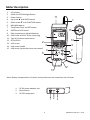
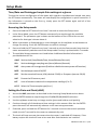
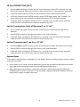
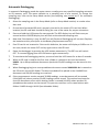
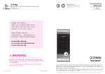
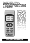
USER GUIDE UVA, UVC Light Meter with Temperature Model SDL470 Introduction Thank you for selecting the Extech Instruments Model SDL470 Ultraviolet Light Meter. The SDL470 measures UVA and UVC light plus temperature. This device is shipped fully tested and calibrated and, with proper use, will provide years of reliable service. Please visit our website (www.extech.com) to check for the latest version of this User Guide, Product Updates, and Customer Support. Features UVA and UVC light measurement in one meter Long wave 365 nm ultra‐violet irradiance measurements Professional UVA meter, used to measure the UVA Radiation from UVA light (black light) Short wave 254 nm ultra‐violet irradiance measurements Professional UVC light meter, measures UVC irradiation from UVC light source Two ranges: 2 mW/cm^2, 20 mW/cm^2 Meter includes two probes: UVA probe and UVC probe UV Sensor with cosine correction filter UV Zero feature Applications include: Monitoring blue light radiation from welding equipment, UV sterilization, graphic arts, photochemical matching, UV EPROM erasure, Photo‐resist exposure, ink curing, adhesives and coatings Microprocessor circuit provides high reliability and durability Separate UV light probe allows the user to measure UV light with optimum positioning Type K and Type J thermocouple thermometer Real time SD memory card Datalogger, built‐in calendar clock, real‐time data recording, with selectable sampling time (rate) from 1 second to 3600 seconds Manual Datalogging (set the sampling rate to 0) Simple, innovative operation, PC not required to setup. Simply use the SD card to transfer data from meter to PC Recorded data includes real‐time calendar clock stamp SD card capacity: 1 GB to 16 GB. LCD with green backlight is easy to read Meter can be set to default on auto power off or manual power off Includes Data hold, Record MA and MIN readings Powered by AA (1.5 V) x 6 batteries or DC 9V adaptor RS232/USB PC computer interface 2 SDL470‐en‐EU v1.0 7/14 Meter Description 1. 2. 3. 4. 5. 6. 7. 8. 9. 10. 11. 12. 13. 14. 15. LCD display HOLD and LCD Backlight button Power button Up arrow ▲ and UNITS button Down arrow ▼ and FUNCTION button MAX‐MIN button Time/Date Check and SET button ENTER and LOG button Side compartment (detailed below) UVA Probe and UVC Probe input plug Type K/J thermocouple socket SD Card Slot 2 UVC sensor UVA probe handle UVA sensor (protective cover not shown) 5 11 1 15 1 14 3 6 4 7 8 13 9 12 Note: Battery compartment, tilt stand, and tripod mount are located on rear of meter 1. DC 9V power adaptor jack 2. Reset button 3. RS‐232 output port 1 2 3 3 SDL470‐en‐EU v1.0 7/14 Operation Function/Measurement Selection Power the meter ON or OFF by pressing and holding the Power button for at least 2 seconds. If this is the first time the meter is powered ON or if the batteries have been replaced, the meter may display the SET DATE message to remind user to set the date and time (see the SETUP MODE section for setting the time and date). Scroll through the three measurement options (UVA LIGHT, UVC LIGHT, or TYPE K/J THERMOMETER) by pressing and holding the Function button. The display icons are ‘A’ for UVA Light, ‘C’ for UVC Light, and ‘tP’ for Type K/J thermometer. UVA Light Meter Insert the UVA Probe Plug into the Probe Input Socket. Switch the meter ON by pressing and holding the Power button for at least 2 seconds. Select the UVA Light Meter option as described above in the Function/Measurement Selection section. The display will show the mW/cm^2 unit of measure. The meter is now ready to make UVA light measurements. Holding the Sensor Handle, face the UVA Sensor toward the source of UVA light. The display will show the measurement reading. UVC Light Meter Insert the UVC Probe Plug into the Probe Input Socket. Switch the meter ON by pressing and holding the Power button for at least 2 seconds. Select the UVC Light Meter option as described above in the Function/Measurement Selection section. The display will show the mW/cm^2 unit of measure. The meter is now ready to make UVC light measurements. Holding the Sensor Body, face the UVC Sensor toward the source of UVC light. The display will show the measurement reading. LCD Backlight Press and hold the HOLD/Backlight button for 2 seconds to switch the LCD backlight ON/OFF. ZERO Adjustment Cover the UVA light sensor or the UVC light sensor with the protective cover. If the meter display does not read zero, press and hold the up and down arrow buttons simultaneously for at least 3 seconds. The display will automatically zero. Remove the sensor cover to begin taking measurements. 4 SDL470‐en‐EU v1.0 7/14 Type K/J Thermometer Measurements Do not connect either the UVA or UVC probes to the meter while taking temperature readings. Plug a thermocouple (not supplied) into the temperature probe jack at the top of the meter. Switch the meter ON by pressing and holding the Power button for at least 2 seconds. Select the Thermocouple function as described in the Function/Measurement Selection section. The meter display will show the temperature measurement along with the ‘K’ or ‘J’ thermocouple indicator. The meter defaults to Type K thermocouple; refer to the Setup Mode section for instructions on how to change the thermocouple type. Data Hold Press the HOLD button momentarily to freeze the displayed reading. The HOLD display icon will appear. Press the HOLD button again to release the display The HOLD display icon will switch OFF. MAX‐MIN Reading Store/Recall For a given measurement session, this meter can record the highest (MAX) and the lowest (MIN) readings. Press the MAX‐MIN button momentarily (REC icon appears) The meter is now recording the MAX and MIN readings. Press the MAX‐MIN button again to view the current MAX readings (MAX icon appears). The readings on the display are now the highest readings encountered since the REC icon was switched on (when the MAX‐MIN button was first pressed). Press the MAX‐MIN button again to view the current MIN readings (MIN icon appears). The readings on the display are now the lowest readings encountered since the REC icon was switched on (when the MAX‐MIN button was first pressed). To exit the MAX‐MIN mode, press and hold the MAX‐MIN button for at least 2 seconds. The meter will beep, the REC‐MAX‐MIN icons will switch off, the MAX‐MIN memory will clear, and the meter will return to the normal operating mode. 5 SDL470‐en‐EU v1.0 7/14 Setup Mode Time/Date and Datalogger Sample Rate settings at a glance To view the current configuration of the meter with regard to time/date and sample rate press the SET button momentarily. The meter will now display the configuration in quick succession. If the information is missed on the first try, simply press the SET button again until all of the information is noted. Accessing the Setup mode 1. Press and hold the SET button for at least 2 seconds to access the Setup menu. 2. In the Setup Mode, press the SET button momentarily to step through the available parameters. The parameter type is shown on the bottom of the LCD and the current selection for that type is shown above it. 3. When a parameter is displayed that is to be changed, use the up/down arrow buttons to change the setting. Press the ENTER button to confirm a change. 4. Press and hold the SET button for at least 2 seconds to exit the Setup mode. Note that the meter automatically switches out of the Setup mode if no key is pressed within 7 seconds. 5. The available Setup parameters are listed below. Additional detailed information is provided below this list: dAtE Set the clock (Year/Month/Date; Hours/Minutes/Seconds) SP‐t Set the datalogger sampling rate (Hours/Minutes/Seconds) PoFF Auto power‐off management (Enable or disable the auto‐power off function) bEEP Set the beeper sound ON/OFF dEC Set the numerical format; USA (decimal: 20.00) or European (comma: 20,00) Sd‐F Format the SD memory card t‐CF Units of measure selection for temperature readings (C or F) tYPE Select the Thermocouple type (K or J) Setting the Date and Clock (dAtE) 1. Access the dAtE parameter as described in the Accessing Setup Mode section above. 2. Use the ENTER button to step through the YY/MM/DD/HH/MM/SS selections. 3. Use the up/down arrow keys to change a value (press and hold to scroll quickly). 4. Continue through all of the date and time settings in this manner. After the last ENTER press the meter will automatically advance to the next setup parameter. 5. If desired, press and hold the SET button for 2 seconds to exit to the normal operation mode (or wait 7 seconds for the meter to automatically exit). 6. The clock will keep accurate time even when the meter is switched off. However, if the battery expires the clock will have to be reset after fresh batteries are installed. 6 SDL470‐en‐EU v1.0 7/14 Setting the Datalogger Sampling Time (Rate) ‘SP‐t’ 1. From the SP‐t parameter the sampling rate can be set to ‘0’ seconds (for manual logging) or 1, 2, 5, 10, 30, 60, 120, 300, 600, 1800, 3600 seconds for auto logging. 2. Use the up/down arrow buttons to select the sampling rate (press and hold for quick scroll). 3. Press the ENTER button to confirm the entry and automatically step to the next parameter. 4. Press and hold the SET button for 2 seconds to exit to the normal operation mode (or wait 7 seconds for the meter to automatically exit). Enabling/Disabling the Auto Power OFF Feature (PoFF) 1. From the PoFF parameter screen use the arrow buttons to select ON (enable) or OFF (disable). With the Auto Power OFF feature enabled, the meter will automatically switch OFF after 5 minutes of inactivity. 2. Press ENTER to confirm setting and to step to the next parameter. 3. If desired, press and hold the SET button for 2 seconds to exit to the normal operation mode (or wait 7 seconds for the meter to automatically exit). Set the Beeper Sound ON or OFF (bEEP) 1. From the bEEP parameter window use the arrow buttons to select ON (enable) or OFF (disable). 2. Press ENTER to confirm setting and to move to the next parameter. 3. If desired, press and hold the SET button for 2 seconds to exit to the normal operation mode (or wait 7 seconds for the meter to automatically exit). Numerical Format (comma or decimal) ‘dEC’ European and USA numerical formats differ. The meter defaults to USA mode where a decimal point is used to separate units from tenths, i.e. 20.00; The European format uses a comma, i.e. 20,00 to separate units from tenths. To change this setting: 1. From the dEC parameter screen use the arrow buttons to select USA or Euro (European). 2. Press ENTER to confirm setting and to move to the next parameter. 3. If desired, press and hold the SET button for 2 seconds to exit to the normal operation mode (or wait 7 seconds for the meter to automatically exit). 7 SDL470‐en‐EU v1.0 7/14 SD Card FORMATTING (Sd‐F) 1. From the Sd‐F parameter screen use the arrow buttons to select YES to format the card (select NO to abort). Note that all data on the card will be lost if formatting is attempted. 2. If NO was selected, press ENTER to confirm and to move to the next parameter. 3. If YES was selected, press ENTER and then press ENTER again when ‘ent’ is shown. The meter steps to the next parameter automatically after the SD card is formatted. 4. If desired, press and hold the SET button for 2 seconds to exit to the normal operation mode (or wait 7 seconds for the meter to automatically exit). Set the Temperature Units of Measure (C or F) ‘t‐CF’ 1. From the t‐CF parameter screen use the arrow buttons to select the desired unit of measure. 2. Press ENTER to confirm setting and to move to the next parameter. 3. If desired, press and hold the SET button for 2 seconds to exit to the normal operation mode (or wait 7 seconds for the meter to automatically exit). Set the Thermocouple Type (K or J) ‘tYPE’ 1. From the tYPE parameter screen use the arrow buttons to select the desired sensor type. 2. Press ENTER to confirm setting and to move to the next parameter. 3. If desired, press and hold the SET button for 2 seconds to exit to the normal operation mode (or wait 7 seconds for the meter to automatically exit). System Reset If the meter’s keys become inoperable or if the display freezes the Reset button can be used to reset the instrument. Use a paper clip or similar item to momentarily press the reset button located on the lower right side of the instrument under the snap‐off compartment cover. After pressing the Reset button, switch the instrument ON by pressing and holding the POWER key for at least 2 seconds. If using the power adaptor unplug the adaptor and then plug it back in again to power the meter. 8 SDL470‐en‐EU v1.0 7/14 Datalogging and PC Interface Types of Data Recording Manual Datalogging: Manually log up to 99 readings onto an SD card via push‐button press. Automatic Datalogging: Automatically log data onto an SD memory card where the number of data points is virtually limited only by the card size. Readings are logged at a rate specified by the user. SD Card Information Insert an SD card (from 1G size up to 16G; however 4GB sized cards or smaller are recommended) into the SD card slot at the bottom of the meter. The card must be inserted with the front of the card (label side) facing toward the rear of the meter. If the SD card is being used for the first time it is recommended that the card be formatted and the logger’s clock set to allow for accurate date/time stamping during Datalogging sessions. Refer to the Setup Mode section for SD card formatting and time/date setting instructions. European and USA numerical formats differ. The data on the SD card can be formatted for either format. The meter defaults to USA mode where a decimal point is used to separate units from tenths, i.e. 20.00. The European format uses a comma, i.e. 20,00. To change this setting, refer to the Setup Mode section. Manual Datalogging In the manual mode the user can manually log one reading at a time onto the SD card (up to 99 readings). 1. Set the sampling rate to ‘0’ seconds as described in the Setup Mode section. 2. Press and hold the LOGGER button for at least 2 seconds (the LOGGER icon will appear). 3. If an SD card is not installed in the meter, the display will show an error message (CARD). 4. In an SD card is installed, the lower portion of the display will show P‐n (n = memory position number 1‐99). 5. Use the ▲ and ▼ buttons to select one of the 99 data memory positions in which to record. 6. Momentarily press the LOG button to store the reading (the SCAN CARD display icon will show briefly as the reading is stored in the selected location). Repeat steps 5 and 6 for up to 99 readings. 7. To exit the manual Datalogging mode, press and hold the LOG button for at least 2 seconds. The Pn and LOGGER icons will switch off. 9 SDL470‐en‐EU v1.0 7/14 Automatic Datalogging In automatic Datalogging mode the meter stores a reading at a user‐specified sampling rate onto an SD memory card. The meter defaults to a sampling rate of one second. To change the sampling rate, refer to the Setup Mode section (the sampling rate cannot be ‘0’ for automatic Datalogging): 1. Select the sampling rate in the Setup Mode (refer to Setup Mode section) to a value other than zero. 2. Ensure that a formatted SD card is properly inserted in the meter’s SD card slot. When inserted, the SD card label should be facing the rear of the meter for proper orientation. 3. Press and hold the LOG button for two seconds. The REC display icon will flash once per second and the LOGGER display icon will flash at the selected sampling rate. 4. Note that if the battery is low, the BAT icon will flash and Datalogging will not start. Replace the batteries at this point (refer to the Battery Replacement section). 5. If an SD card is not inserted or if the card is defective, the meter will display a CARD error. In this case, switch the meter OFF and try again with a valid SD card. 6. Pause the datalogger by pressing the LOG button momentarily. The REC icon will switch OFF. To resume logging press the LOG button again momentarily. 7. To terminate the Datalogging session, press and hold the LOG button for at least 2 seconds. 8. When an SD card is used for the first time a folder is created on the card and named UVA01. Up to 99 spreadsheet documents (each with 30,000 readings) can be stored in this folder. 9. When Datalogging begins a new spreadsheet document named UVA01001.xls is created on the SD card in the UVA01 folder. The data recorded will be placed in the UVA01001.xls document until 30,000 readings are reached. 10. If the measurement session exceeds 30,000 readings, a new document will be created (UVA01002.xls) where another 30,000 readings can be stored. This method continues for up to 99 documents, after which another folder is created (UVA02) where another 99 spreadsheet documents can be stored. This process continues in this same fashion with folders UVA03 through UVA10 (last allowable folder). 10 SDL470‐en‐EU v1.0 7/14 SD Data Card to PC Data Transfer 1. Complete a Datalogging session as detailed above in the previous sections. Hint: For the first few tests, simply record a small amount of test data. This is to ensure that the Datalogging process is well understood before committing to critical, large scale Datalogging. 2. With the meter switched OFF, remove the SD Card. 3. Plug the SD Card directly into a PC SD card reader. If the PC does not have an SD card slot, use an SD card adaptor (available at most outlets where computer accessories are sold). 4. Power on the PC and run a spreadsheet software program. Open the saved documents in the spreadsheet software program (see example spreadsheet data screen below). Spreadsheet data example RS‐232/USB PC Interface For streaming of data to a PC via the RS232 Output jack (3.5mm), the optional 407001‐USB kit (RS232 to USB cable and driver CD) along with the 407001 software (available free at www.extech.com/SDL470) are required. AC Power Adaptor This meter is normally powered by six (6) 1.5V ‘AA’ batteries (located in the rear battery compartment). An optional 9V power adaptor is available. When the adaptor is used, the meter is permanently powered on and the power button will be disabled. The AC adaptor jack 11 SDL470‐en‐EU v1.0 7/14 Battery Replacement When the battery icon appears on the LCD, the batteries must be replaced. Several hours of test time are possible from when the battery symbol first appears but when critical data is at stake it’s always best to start with a fresh set of batteries. 1. Remove the two Philips screws (above the tilt stand) on the rear of the meter. 2. Carefully open the battery compartment to access the batteries. 3. Remove the existing batteries and replace with six (6) fresh 1.5V AA batteries observing proper polarity. 4. Close the compartment and secure with the two screws before attempting to use the meter. 5. Note that the time and date must be reset when the batteries are replaced (see the SETUP Mode section of this user guide). Never dispose of used batteries or rechargeable batteries in household waste. As consumers, users are legally required to take used batteries to appropriate collection sites, the retail store where the batteries were purchased, or wherever batteries are sold. Disposal: Do not dispose of this instrument in household waste. The user is obligated to take end‐of‐life devices to a designated collection point for the disposal of electrical and electronic equipment. Battery Safety Reminders o Please dispose of batteries responsibly; observe local, state, and national regulations. o Never dispose of batteries in a fire; batteries may explode or leak. o Never mix battery types; install new batteries of the same type. 12 SDL470‐en‐EU v1.0 7/14 Specifications General Specifications Display Measurements UVA, UVC selection UV Sensor spectrum UV sensor UV light zero adjust Data storage/recall Datalogger Memory SD card Advanced settings Temperature compensation Data Hold Memory Recall Display sampling rate Data output Operating Temperature Operating Humidity Power Supply Power Consumption Weight Dimensions Backlit LCD size: 52 mm x 38 mm (2.0 x 1.5”) UV light, UVA and UVC Type K or J thermocouple temperature Front push‐button 240 nm to 390 nm Exclusive photo sensor with cosine correction filter Push‐button Records Max and Min readings with recall Auto 1 second to 3600 second sample rate Manual Button press (sample rate set to ‘0’) 1G to 16GB SD Card (for best results use a 4GB or smaller card) Real‐time calendar clock, decimal point selection for SD card data, Auto power OFF management, beeper on/off control, selectable thermocouple Type J or K, selectable temperature units, selectable datalogger sample rate, SD memory card formatting Auto compensation for the Type K/J thermocouple thermometer Freezes the displayed reading For MAX and MIN recall 1 second approx. RS‐232/USB PC interface Connect the optional RS‐232 cable UPCB‐02 for RS‐232 plug Connect the optional USB cable USB‐01 for USB type plug 0oC to 50oC (32oF to 122oF) Less than 85% RH Alkiline or heavy duty 1.5V AA batteries x 6 or 9V AC adaptor Normal operation (without SD storing and with display backlight OFF): 6.5mA DC approx. With SD card storing but display backlight OFF: 30mA DC approx. With the LCD backlight ON the power consumption increases by 16mA DC approx. Meter: 351g (11.3 oz.); UVA Probe: 100g (3.2 oz.); UVC Probe: 103g (3.3 oz.) Meter: 177 x 68 x 45mm (7.0 x 2.7 x 1.8”) UVA Probe head: 45 mm diameter x 32 mm (1.8 dia. x 1.3”) UVA Probe handle: 125 x 24 mm diameter (5.0 x 0.9” dia.) 13 SDL470‐en‐EU v1.0 7/14 Accessories included Optional Accessories UVC probe: 38mm diameter x 25 mm (1.5 dia. x 1.0”) Instruction manual, UVA light sensor, UVC light sensor, hard‐shell carrying case, batteries, and user guide Type K thermocouple probe, AC to DC 9V power adaptor, USB cable (USB‐01), RS‐232 cable (UPCB‐02), and data acquisition software Electrical Specifications (23oC ±5oC) UV Light (UVA, UVC) Ranges and Resolution Range 1: (2mW/cm^2) 1.999 mW/cm^2 x 0.001 mW/cm^2 Range 2: 20mW/cm^2 Accuracy ± (4% FS + 2 digits); FS= Full Scale UVA Calibration executed under UVA light and compared with UVA light meter standard UVC Calibration executed under UVC light and compared with standard UVC light meter standard Type K/J Thermocouple Thermometer Sensor type Resolution Range Accuracy ± (0.2% + 0.5oC) Type K 0.1C ‐50.0 to 1300.0oC o o ‐50.1 to ‐100.0 C ± (0.2% + 1.0 C) o 0.1F ‐58.0 to 2372.0 F ± (0.2% + 1.0oF) ‐58.1 to ‐148.0oF ± (0.2% + 1.8oF) o o Type J 0.1C ‐50.0 to 1100.0 C ± (0.2% + 0.5 C) o ‐50.1 to ‐100.0 C ± (0.2% + 1.0oC) 0.1F ‐58.0 to 2012.0oF ± (0.2% + 1.0oF) o o ‐58.1 to ‐148.0 F ± (0.2% + 1.8 F) Note: Above specifications tested with an RF strenghth less than 3V/M and a frequency less than 30MHz Copyright © 2014 FLIR Systems, Inc. All rights reserved including the right of reproduction in whole or in part in any form www.extech.com 14 SDL470‐en‐EU v1.0 7/14