1
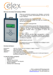
E L E X
euro
USER MANUAL
Models:
ELEX euro 2400
ELEX euro 2000
ELEX euro 1500
ELEX euro 1000
THERMOFILM AUSTRALIA 27 Rosalie Street, Springvale VIC 3171
Ph: 03 9562 3455
Fx: 03 9548 3979
www.thermofilm.com.au
H E A T E R S
1. Important Safety Instructions
2. Specification Data
3. Operating Instructions
3.1
Control Panel Guide
3.2
Switching on the Unit
3.3
Programming the Timer
3.3.1 Programming the Clock
3.3.2 Setting the Temperature
3.3.3 Selecting the Constant Heating Operation
3.3.4 Selecting the Constant Frost Protection Operation
3.3.5 Setting the Self Set Weekly Operation
3.3.6 Adjust the Temperature of a Running Programme
3.3.7 Changing Time for Daylight Savings
3.3.8 Programme Back-Up
3.3.9 Locking the Control Panel
3.4
Safety Notes
3.5
Maintenance
4. Installation Instructions
4.1
Installation Location
4.2
Wall Mounting Bracket
4.3
Castor Wheel Set
4.4
Electrical Connection
4.5
Safety Notes
5. Warranty
P A N E L
TABLE OF CONTENTS
Rev C JUL13
C O N V E C T I V E
ELEX euro CONVECTIVE PANEL HEATER
E L E X
euro
•
•
•
•
•
•
•
•
•
•
•
•
•
•
•
•
•
•
•
•
•
•
•
•
•
THERMOFILM AUSTRALIA 27 Rosalie Street, Springvale VIC 3171
Ph: 03 9562 3455
Fx: 03 9548 3979
www.thermofilm.com.au
H E A T E R S
•
•
•
P A N E L
•
•
Prior to installing and operating the heater, read these instructions carefully and retain
for future reference.
Indoor use only.
Ensure the rated voltage is 230-240V.
Do not install the heater directly below a socket.
Always operate heater in an upright position with the control panel at the top. If using castor
wheel set, heater should be positioned on a flat horizontal surface.
Arrange cord away from traffic areas so that it will not be tripped over.
Do not place the cable under carpets /rugs.
Do not remove plug from power socket by pulling the supply cord. Always grip plug.
Do not operate this appliance if the cable or plug becomes damaged.
In case of heater fault or damaged supply lead, the appliance should be returned to the
distributor / manufacturer for repair.
Ensure the appliance is switched OFF before connecting to the mains power supply.
Do not cover or restrict airflow to the inlet or outlet grills in any manner, as the appliance
may overheat and become a fire risk.
Do not insert or allow foreign objects or metal utensils to enter any grill opening, as this may
cause an electric shock or fire damage to the appliance.
Do not operate in areas where gasoline, paint or other flammable liquids are used or stored.
Switch off the power supply and unplug from the mains socket when not in use, before
cleaning or changing accessories.
To prevent overload and blown fuses, do not plug other appliance into same power outlet
(receptacle).
Do not immerse in liquid or allow liquid into the interior of the appliance, as this could create
an electric shock hazard.
Do not reach for an appliance that has fallen into water. Switch off at supply and unplug
immediately.
Do not operate appliance with wet hands. Always ensure that hands are dry before operating
or adjusting any switch on the product or touching the plug and mains supply connections.
Never leave the appliance unattended when connected to the mains power supply.
Do not cover. NEVER use the heater to dry clothes or similar articles.
Do not position the appliances close to curtains or other combustible materials. Keep
combustible material such as furniture, cushions, bedding, paper, clothes, curtains etc. at least
1.0m away from the heater.
The most common cause of overheating is deposits of dust or fluff in the appliance. Ensure
these deposits are removed regularly by unplugging the appliance and vacuum cleaning air
vents and grilles.
This appliance heats up when in use. To avoid burns, do not let bare skin touch hot surface.
Switch off and let cool down before moving. Store the heater in cool, dry location when not
in use.
Do not use this appliance with a programmer, timer or any other devices that switches the
appliances on automatically.
Do not use an extension cable with this appliance.
Do not use the appliance in rooms less than 4m2 area.
This appliance is not intended for use by persons (including children) with reduced physical,
sensory or mental capabilities, or lack of experience and knowledge, unless they have been
given supervision or instruction concerning use of the appliance by a person responsible for
their safety.
Children should be supervised to ensure that they do not play with the appliance.
If used as a portable heater, do not use in the immediate surroundings of a bath, a shower or a
swimming pool.
C O N V E C T I V E
1. Important Safety Instructions
euro
E L E X
Model
Power (W)
Voltage (V)
Dimension (mm)
ELEX euro 1000
1000W
240V~50Hz
420 x 440 x 105
ELEX euro 1500
1500W
240V~50Hz
580 x 440 x 105
ELEX euro 2000
2000W
240V~50Hz
740 x 440 x 105
ELEX euro 2400
2400W
240V~50Hz
1000 x 440 x 105
3. Operating Instructions
The control panel features an accurate electronic thermostat and 7 day programmable timer. This
timer has a constant heating operation, constant frost protection operation and a self-set weekly
operation programme.
P A N E L
3.1 Control Panel Guide
Main Power Switch (1/ 0 – ON / OFF)
Unit Power button (ON / OFF)
Copy button
Down button
Up button
Temperature button
Timer button
Programming button
Mode Selection button
LCD screen
Power On light
3.2 Switching on the Unit
Press the main power switch (1) on the right hand side of panel. Press the POWER button (2) on the
control panel. This turns the unit ON, and the LCD screen (10) will illuminate, displaying “[M]”
(Monday) and 12:00 as the default day and time setting.
Constant Heating Operation at 21°C is the default operation setting.
Note: The red “ON” indicator light (11) illuminates when the heating element is operating.
Upon first use, the heater may give off some fumes (this is normal).
Ensure that the room is ventilated (for example, open a window).
THERMOFILM AUSTRALIA 27 Rosalie Street, Springvale VIC 3171
Ph: 03 9562 3455
Fx: 03 9548 3979
www.thermofilm.com.au
H E A T E R S
12345678910 11 -
C O N V E C T I V E
2. Specification Data
euro
E L E X
The timer must be set in order to use the Self-Set Weekly Operation Programme.
3.3.1 Programming the Clock
Day Setting
Press timer button.
The “[ ]” symbol will flash around M (Monday). Use the up
and down
buttons to move the “[ ]” symbol to the correct day.
M
Monday
T
Tuesday
W
Wednesday
T
Thursday
F
Friday
S
Saturday
S
Sunday
Note: The “[ ]” will flash when used for the first time, or after a lengthy absence of power, and the
red “ON” light will glow.
C O N V E C T I V E
3.3 Programming the Timer
Hour Setting
The hour number will flash. Use the up
and down
buttons to set
Minute Setting
Press the timer button.
set the correct minute.
Press the timer button
The minute number will flash. Use the up
and down
buttons to
again to complete the timer setting.
3.3.2 Setting the temperature
Press the temperature setting button
. The centre of the digital clock face will flash with the
heating operation and temperature setting (e.g. “CO 21”). Use the up
and down
to set the required temperature. Note: The default temperature is 21 ºC.
Press the temperature button
buttons
again to complete the temperature setting.
3.3.3 Selecting the Constant Heating Operation
The constant heating operation is the default setting of the heater, and this will run when the heater is
used for the first time, or after a lengthy absence of power. The temperature setting may be altered as
per section 3.3.2.
To select this setting, press the mode button
. Use the up
and down
the CO programme. The temperature setting may be altered as per section 3.3.3.
buttons to select
Press the mode button
again to terminate the setting. The mode symbol will stop flashing. The
mode is now active and will run in “real time”.
THERMOFILM AUSTRALIA 27 Rosalie Street, Springvale VIC 3171
Ph: 03 9562 3455
Fx: 03 9548 3979
www.thermofilm.com.au
H E A T E R S
The control panel will show the current time and the unit will operate under the default programme
of “CO” (Constant Heating Operation).
P A N E L
Press timer button.
the correct hour.
E L E X
euro
To protect against freezing temperatures in cold climate areas you can programme the heater for frost
protection by reducing the set temperature to 5°C while the heater is in “CO” mode.
When the temperature is set to 5°C the
symbol will display on the screen and the heater will
operate when the room temperature falls below 5°C.
3.3.5 Setting the Self Set Weekly Operation
This function allows you to program for ON/OFF times 24 hours a day, 7 days per week.
Press the mode button
. The mode symbol will flash.
Use the up
or down
Press the mode button
button to select the programme mode of SS.
again to complete the setting. The mode symbol SS will stop flashing.
Selecting the Day
Press the programme button
. The symbol “[ ]” will appear around the current day e.g.
M (Monday). The time will show (00:00, midnight), and the symbol PROG are displayed.
Selecting Times for a Full 24 hour Day
Note: The zone for “OFF” is blank and the zone of “ON” is black on the digital clock face diagram.
The up button
is used for setting the “ON” Zone, and the down button
is used for setting
the “OFF” Zone. The timer will start at 00:00, and each push of the up or down button will advance
For example, you would like to make the unit work from 1:00 to 4:00,
11:00-13:00, and from 17:00 to 23:00.
Step 1: Press the button
to 1:00 will be blank (OFF).
. The time will change from 00:00 to 1:00, and the zone between 24:00
Step 2: Press the button
black (ON).
until the time advances to 4:00, and the zone between 1:00 and 4:00 be
Step 3: Press the button
be blank (OFF).
until the time advances to 11:00, and the zone between 4:00 to 11:00
Step 4: Press the button
will be black (ON).
until the time advances to 13:00, and the zone between 11:00 to 13.00
THERMOFILM AUSTRALIA 27 Rosalie Street, Springvale VIC 3171
Ph: 03 9562 3455
Fx: 03 9548 3979
www.thermofilm.com.au
H E A T E R S
the clock by one hour. Push the appropriate
or
button to set the desired “ON” or “OFF”
time for the day. You must programme the full 24 hour ON / OFF period (until the time reaches
00:00) for the timer to function correctly.
Press the programme button
to complete the setting for the day.
P A N E L
If you want the programme to start another weekday, for example the Tuesday, press the
timer button
consecutively, until the symbol “[ ]” surrounds T (Tuesday) on the screen.
C O N V E C T I V E
3.3.4 Selecting the Constant Frost Protection Operation
E L E X
euro
until the time advances to 17:00, and the zone between 13:00 to 17:00
Step 6: Press the button
will be black (ON).
until the time advances to 23:00, and the zone between 17:00 to 23:00
Step 7: Press the button
will be blank (OFF).
until the time advances to 00:00, and the zone between 23:00 to 24:00
Step 8: Press the programme button
to complete the setting for the day. The control panel
will now show the correct day. The programme is now active and is running on ‘real time’.
Note: You must programme the full 24 hour ON / OFF period (until the time reaches 00:00) for the
timer to function correctly. If you go past the 00:00 (and move to 01:00) you will need to programme
the 24 hour programme for that day again.
Copy the 24-hour program
If you would like the same 24-hour program to work for another day or days in the week, the
programme can be copied onto the selected day.
Step 1: Press the programme button
(Monday).
Step 2: Press the copy button.
around the M will flash.
and then press the
button to move the “[ ]” to M
The symbol “COPY” will appear on the LCD screen. The “[ ]”
again, the symbol “COPY”
Step 3: Press the timer button
to move the “[ ]” around T
(Tuesday). The “[ ]” will appear around the M and T.
Step 4: Press the copy button
disappear.
to complete the operation. The “COPY” and [M] symbol will
To copy this same Monday programme to another day, repeat from Step 3.
Press the button
to terminate the “COPY” function. The control panel will now show the
correct day. The programme is now active and is running on ‘real time’.
3.3.6 Adjust the Temperature of a Running Programme
The temperature sensed by the thermostat sensor is relative to the position of the heater in the
room. If the actual temperature is higher than the setting, compensate this by adjusting the
temperature setting.
THERMOFILM AUSTRALIA 27 Rosalie Street, Springvale VIC 3171
Ph: 03 9562 3455
Fx: 03 9548 3979
www.thermofilm.com.au
H E A T E R S
(If you would like to cancel the COPY order, please press the button
will disappear accordingly.)
P A N E L
For example, you have just created a 24 hour programme for Monday, and you wish to copy
this Monday programme to Tuesday.
C O N V E C T I V E
Step 5: Press the button
will be blank (OFF).
euro
E L E X
Press the temperature button
Use the button up
. The temperature symbol will flash.
or down
button to adjust the comfort temperature.
Terminate by pressing the temperature button
again. The control panel will now show the
correct day. The programme is now active and is running on ‘real time’.
3.3.7 Changing time for Daylight Savings
Press the timer button
twice to make the hour display flash.
In Summer time, press the up
button to advance the timer clock one hour.
In Winter time, press the down button
to set the timer clock back one hour.
twice so that the current program is
3.3.8 Programme Back-Up
In the event of a mains power failure or long period when the heater has been turned off, the timer
and SS programme must be reset by the user. All other pre-set programs and default temperatures
will be saved.
P A N E L
Terminate the operation by again pressing the timer button
displayed on the panel.
C O N V E C T I V E
For example, if the comfort temperature is set at 21°C but the actual room temperature is 24°C,
compensate for this by lowering the setting to 18°C. Similarly, increase the temperature setting if the
actual room temperature is lower than the setting.
3.3.9 Locking the Control Panel
Press the programme button
seconds. A padlock symbol
to make the chosen program (“SS” or “CO”) flash.
and the timer button
at the same time for around three (3)
is displayed on the screen, indicating the all buttons are now locked.
To unlock the control panel, press the programme button
and the timer button
time for around three (3) seconds, and the padlock symbol will disappear.
at the same
3.4 Safety Notes
The air outlet must not be obstructed. For safety reasons
the upper and lower air grilles must never be covered with
items such as washing nor obstructed by items in close
proximity (see figure to right). Objects should not be leant
against the unit nor placed between the unit and the wall.
Never leave combustible materials, such as wood, paper, textiles or flammable items such as wax,
petrol, aerosol cans etc. in the vicinity of the warm air outlet. As with all similar heaters, the flow of
rising air may cause discoloration of the wall.
The appliance must not be operated:
• In areas which are subject to the risk of fire or explosion due to chemicals, dust, gases or
vapors;
THERMOFILM AUSTRALIA 27 Rosalie Street, Springvale VIC 3171
Ph: 03 9562 3455
Fx: 03 9548 3979
www.thermofilm.com.au
H E A T E R S
Press the mode button
E L E X
In the immediate vicinity of pipes or containers which carry or contain combustible or
potentially explosive substances.
For this reason, the minimum clearance intervals must not be undercut.
In workshops or other areas in which the odor of waste gases, oil, petrol, etc. might occur, or in
which work is carried out involving solvents and chemicals, there is a risk of sustained odor burdens
being engendered, and possibly of dirt contamination occurring.
Before using any materials which produce flammable gases or vapors, e. g. laying or sealing parquet or
PVC flooring, or when using spray polishes, spirits and similar materials, ensure the heater is switched
off.
3.5 Maintenance
Do not use abrasive or aggressive cleansers to clean the heater. Use a vacuum cleaner regularly to
clean the upper and lower air grids.
4. Installation instructions
The ELEX euro convective panel heaters are electric heaters designed to be mounted on the
wall or freestanding using the supplied castor wheel set. These units are suitable for heating
enclosed indoor rooms such as bedrooms, studies, offices, living areas and bathrooms.
These installation instructions belong with the heater and must be handed on to the purchaser if the
heater is sold.
P A N E L
ATTENTION!
The installation, electrical connection and first operation of this appliance should be
carried out by a qualified installer. The company does not accept liability for failure of any
goods supplied which have not been installed and operated in accordance with the
manufacturer's instructions.
C O N V E C T I V E
•
euro
4.1 Installation Location
The ELEX euro convective panel heater should be installed according to normal trade practice and
in compliance with legislation in relevant country.
The panel convector is CLASS I and is protected
against splashed water (IP24). Therefore it can be
installed outside the shaded area shown in the bathroom
area
Ensure the safety zones (mm) in diagram (left
hand side) are kept free.
If the wall covering is laid on foam, a spacer the same thickness as the foam must be placed under the
panel heater’s support. This ensures there is free space behind the panel heater to make sure its
control settings are not adversely affected.
THERMOFILM AUSTRALIA 27 Rosalie Street, Springvale VIC 3171
Ph: 03 9562 3455
Fx: 03 9548 3979
www.thermofilm.com.au
H E A T E R S
The ELEX euro convective panel heater was designed to be installed in a residence. Please ask your
distributor before using it for any other purpose.
E L E X
euro
The ELEX euro convective panel heater must not be installed in a
draught likely to affect the control settings (under a ventilating fan, etc.)
4.2 Wall Mounting Bracket
The wall mounting bracket is oriented centrally (See RHS diagram).
Step 1: Loosen the locking plate screw and rotate the locking plate
out of the fixing slot (See RHS images).
Then remove the mounting bracket from the heater.
Step 3: Install the 4 fixing devices in the wall, ensuring they are
more than adequate to safely fix the heater to the wall.
(ST4 expansion screws are suggested).
Step 4: Fix the bracket firmly to the wall using all 4 mounting locations.
Step 5: Mount the heater on the bracket so the bracket protrusions
fix into the 4 slots on the back of the heater. (See RHS diagram).
Rotate the locking plate into the fixing slot and tighten the screw
4.3 Castor Wheel Set
THERMOFILM AUSTRALIA 27 Rosalie Street, Springvale VIC 3171
Ph: 03 9562 3455
Fx: 03 9548 3979
www.thermofilm.com.au
H E A T E R S
To remove the heater, reverse the above operation.
P A N E L
Step 2: Use the wall-mounting bracket as a template for marking
the fixing holes. Position the mounting bracket in the correct
position on the wall and mark the screw-holes through the 4
mounting holes (See RHS diagram).
C O N V E C T I V E
The ELEX euro convective panel heater must not be installed
immediately below a wall socket. The heater must be connected
to a socket outlet or permanent terminal box at least 10cm to one
side of the heater. If the heater is installed in the Bathroom or in
humid area, the socket outlet or permanent terminal box must
conform to the IP24 requirement.
E L E X
euro
This heater is suitable for 230-240V.
Please observe national standards, the regulations of your local electricity supply company as well as
data on the rating label.
Electrical safety!
The ELEX euro convective panel heaters are IP24 protected against splashing water. In humid areas
such as bathrooms, the power socket must be installed at least 25cm above floor level.
Note the details on the rating plate!
The voltage supply must match the requirements on the rating plate. The supply cable must be
correctly sized. The heater must be connected to a socket outlet or permanent terminal box at least
10 cm to one side of the heater.
Please note in general:
Where the ELEX euro convective panel heater is fitted in a room with a bath or shower, ensure the
safety zone defined in IEE Regulations is applied in accordance with the details on the rating plate.
To avoid hazards, if the power cord of the appliance exhibits visible damage it must be
replaced by the manufacturer or his service agent or a qualified electrician.
The ELEX euro convective panel heater is equipped with a safety cut-out that switches the heater off
if it overheats.
Once the heater has switched off due to overheating, remove the cause of the fault, e. g. blocked air
grids. When the heater has cooled down for several minutes it will restart automatically. If the heater
then cuts off again, switch off the heater and call an authorized serviceman.
5. Warranty
P A N E L
4.5 Safety Notes
C O N V E C T I V E
4.4 Electrical connection
The below Warranty Terms and Conditions apply for New Zealand and Australia only. For
international warranty please refer to international warranty terms and conditions.
Provision of this warranty is subject to:
• The ELEX euro product must be installed in accordance with the Installation Instructions and
relevant electrical standards and codes.
• The ELEX euro product must be maintained and cleaned according to instructions detailed in
the Installation Manual.
• There is no warranty expressed or implied with regard to capacity requirements. The selection of
the unit or units depends entirely upon the system design and capacities as determined by the
purchaser.
• The customer has not repaired, opened or altered the product in any unauthorised manner.
• This warranty excludes damage to the product or components arising from circumstances outside
the control of Thermofilm, including, but not limited to, where the product is not used for intended
purpose; where the product has been rectified in any way; incorrect installation; incorrect power
supply; damaged caused during delivery; misapplication, misuse, abuse, vandalism, lack of maintenance
THERMOFILM AUSTRALIA 27 Rosalie Street, Springvale VIC 3171
Ph: 03 9562 3455
Fx: 03 9548 3979
www.thermofilm.com.au
H E A T E R S
Thermofilm warrants to the original owner that ELEX euro products will be free from defects in
materials and workmanship for a period of 24 months for residential use from the date of purchase in
accordance with the following warranty terms and conditions. For commercial use warranty is 12
months.
E L E X
euro
The customer warrants using the product in accordance with:
• Any instructions provided to it by Thermofilm from time to time.
• All government and local regulations, including but not limited to all relevant electrical,
environmental laws and regulations governing the installation, storage, use, handling and maintenance
of the goods.
• All necessary and appropriate precautions and safety measures relating to the installation, storage,
use, handling and maintenance of goods.
All warranty requests for repairs or replacements must be accompanied by a complete “Warranty
Claim Form” available from Thermofilm, together with proof of purchase (and where possible, photos
of the installation) and the heater returned to the place of purchase.
In the event of a warranty claim, the goods need to be returned to the distributor/retailer for
repair/replacement. Contact
Thermofilm Australia Pty Ltd
27 Rosalie Street, Springvale, Victoria 3171,
AustraliaTelephone: (03) 9562 3455,
Email: [email protected]
THERMOFILM AUSTRALIA 27 Rosalie Street, Springvale VIC 3171
Ph: 03 9562 3455
Fx: 03 9548 3979
www.thermofilm.com.au
H E A T E R S
Our goods come with guarantees that cannot be excluded under the Australian Consumer Law. You are
entitled to a replacement or refund for a major failure and for compensation for any other reasonably
foreseeable loss or damage. You are also entitled to have the goods repaired or replaced if the goods fail to be
of acceptable quality and the failure does not amount to a major failure.
P A N E L
Should products be determined as damaged on arrival, immediately notify the transport company of
the condition and have them noted on the freight documents. If damage is discovered after unpacking,
demand immediate inspection by the transportation company and insist that a record of the damage is
made on the freight documentation.
C O N V E C T I V E
or accident.
• Thermofilm’s obligations under this warranty are limited to repair or replacement at Thermofilm’s
factory of any components of the product which Thermofilm identifies to its satisfaction to be
defective.
• Transportation charges involved in return of the product to the Thermofilm factory (or any other
location authorised in writing by Thermofilm) is the sole responsibility of the customer.
• All products are inspected and tested before despatch and are at the risk of the purchaser after
the shipment from the Thermofilm factory, if not delivered by Thermofilm to destination.
• Discolouration of the surface may occur after a period of time, this does not constitute a
warrantable event.
• No products or components will be supplied in advance of an examination of the faulty product or
components by Thermofilm or an authorized representative of Thermofilm.
• Thermofilm does not participate in any site related costs or labour expenses incidental to
replacement of parts, repairing, removing, installing, servicing, transportation or handling of parts to
complete products, and assumes no liability on parts repaired or replaced without written
authorisation. Thermofilm shall not be liable for any default or delay in performance of its warranty
obligations caused by any circumstances beyond its control, including, but not limited to, judicial or
government restrictions, strikes, fires, floods, abnormal weather conditions, delayed supply of
components.