1
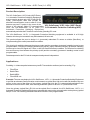
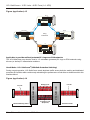
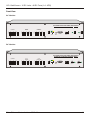
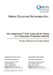
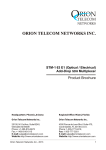
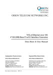
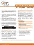
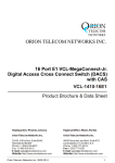
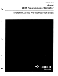
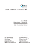
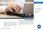
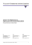
RION TELECOM NETWORKS ORION TELECOM NETWORKS INC. VCL-SafeCommTM 16 E1 Links (48 E1 Ports) (1+1 Automatic Protection Switch) Product Brochure & Data Sheet Headquarters: Phoenix, Arizona Regional Office: Miami, Florida Orion Telecom Networks Inc. Orion Telecom Networks Inc. 20100, N 51st Ave, Suite B240, Glendale AZ 85308 Phone: +1 480-816-8672 Fax: +1 480-816-0115 E-mail: [email protected] Website: http://www.oriontelecom.com 4000 Ponce de Leon Blvd. Suite 470, Coral Gables, FL 33146 U.S.A. Phone: 1-305-777-0419, Fax: 1-305-777-0201 E-mail: [email protected] Website: http://www.oriontelecom.com Orion Telecom Networks Inc. - 2012-14 1 VCL-SafeComm TM 16 E1 Links - 48 E1 Ports (1+1 APS) Product Description: The VCL-SafeComm, 16 E1 Links (48 E1 Ports), 1+1 Automatic Protection Switching Equipment may be used to protect upto 16 E1 Links (48 E1 Ports), point-to-point links and provide an alternate communication route to each E1 Link between any two E1 points. In the event of the failure of the primary (Main) E1 communication VCL-SafeComm, 16 E1 Links (48 E1 Ports) route, the VCL-SafeComm, 16 E1 Links (1+1 1+1 Automatic Protection Switching (APS) Automatic Protection Switching Equipment) automatically switches the E1 traffic to a secondary (standby) E1 route. The VCL-SafeComm, 16 E1, 1+1 Automatic Protection Switching equipment is available in a 2U high chassis, which may be mounted in any DIN standard,19-Inch rack. This product allows the user to design 1+1 (protected) redundant E1 routes on similar (fiber-fiber), or complementing (fiber-radio) transmission mediums. The criterion for switching between the primary (main) and the secondary (protected / standby) routes is user programmable. Criterion for switching between the primary (main) and the secondary (protected / standby) routes may be Loss-Of-Signal on E1 links, or AIS (All-Ones AIS alarm) condition. The criterion for switching time and recovery time between the primary (main) and the secondary (protected / standby) routes is user programmable. Data transported on the E1 Links is transparent and protocol independent. Applications: Providing 1+1 alternate paths between any two E1 Transmission mediums (active+standby). E.g.: Fiber/Fiber Radio/Fiber Radio/HDSL Fiber/HDSL etc. Example: The user may deploy the VCL-SafeComm, 16 E1, 1+1 Automatic Protection Switching Equipment to provide an alternate communication route between an optical fiber link and a radio link between any two points. In the event of the failure of the primary (optical fiber) link the E1 is automatically switched to the alternate route over the E1 radio, thus ensuring maximum uptime on all such 1+1 protected E1 Links. Once the primary (optical fiber) E1 Link on the optical fiber is restored, the VCL-SafeComm, 16 E1, 1+1 Automatic Protection Switching Equipment automatically restores the communication to the primary (optical fiber) E1 Link. The switching time and restoration criterion is user programmable. Orion Telecom Networks Inc. - 2012-14 2 VCL-SafeComm TM 16 E1 Links - 48 E1 Ports (1+1 APS) Application Diagram: Figure (application) # 1 Microwave System Microwave System E1 SafeComm 16 E1 Links (48 E1 Ports) E1 Stby Stby Main Main SafeComm 16 E1 Links (48 E1 Ports) Upto 16 E1s Upto 16 E1s Fiber Converter E1 Fiber Fiber Converter E1 Point-to-Point Application: May be used in a point-to-point configuration to provide 1+1 Protected /Alternate Routing Path between any two points, using diverse (or similar) E1 transmission mediums. Figure (application) # 2 TYPICAL STAR CONFIGURATION #A #B #C BTS BTS BTS 1 1+ R ed d un in tL an 1 k + 1 Re 1 + 1 Redundant Link MW LINK MW LINK MW LINK du nd a nt Li n k BSC Point-to-Multipoint Application: To provide 1+1 Redundant E1 Link(s) between a single (BSC) location and multiple (BTS) locations using diverse (or similar) E1 transmission mediums. Orion Telecom Networks Inc. - 2012-14 3 VCL-SafeComm TM 16 E1 Links - 48 E1 Ports (1+1 APS) Figure (application) # 3 Site A 7 E1s 7 E1s 7 E1s 9 E1s Radio Link k Radio Link E1 R ad io L in E1 Ra di o Lni k Site B Central Site 16 E1s 16 E1s Radio Link BSC Ring Protection Radio Link 4 E1s 4 E1s 12 E1s 16 E1 APS 16 E1 APS Optic Multiplexer Optic Multiplexer 4 E1s rL Op ti be Fi cF i be rL tic Op ink 16 E1s ink 11 E1s Optic Multiplexer 5 E1s Optic Multiplexer 5 E1s 5 E1s Site C Application to provide resilient (protected) E1 rings over PDH networks: The VCL-SafeComm may also be used in 1+1 redundant (protected) E1 rings on PDH networks using diverse (or similar) E1 transmission mediums. How It Works - VCL-SafeCommTM (With Path Protection Switching) During normal operation, VCL-SafeComm sends duplicate traffic across both the working and dedicated protection E1 facilities while continuously maintaining the performance of both links to determine which link shall be utilized. Figure (application) # 4 E1 Link VCL-SafeComm VCL-SafeComm Working Link E1 Link Protection Link (Duplicate) Mobile Switching Office Orion Telecom Networks Inc. - 2012-14 Remote Cell Site 4 VCL-SafeComm TM 16 E1 Links - 48 E1 Ports (1+1 APS) Features & Highlights: High density protection switching equipment (upto 16 E1 Links; i.e. 48 E1 Ports) To provide an independent point-to-point, protected E1 Llink between two “E1 USER PORTS” on similar (example fiber-fiber), or dissimilar (fiber-radio) mediums To provide 1+1 E1 redundancy Remote system configuration and management interface through "CLI" text based commands using Telnet and GUI (Graphical User Interface) Provide 1+1 Protection Routing / Path between BSC and BTS These ensure that mission critical voice, data, control and management traffic are properly supported and maintained even during E1 backhaul facility outages. When the primary (working) link fails, the E1 traffic is automatically switched to the standby (secondary) link to ensure maximum uptime Through the comprehensive remote configuration and alarm management capabilities of the VCL-SafeComm, 16 E1, 1+1 Automatic Protection Switching Equipment the product may be used to improve network reliability and control Traffic Protection Alternate Facility Advantages Service Differentiation Agreements Increased Network Reliability Resilience Media and Path Diversity Remote Management Alarm logging and monitoring. Benefits: Competitive Service Level Back-haul Network Technology Migration User Programmable 1+1 Protection Parameters: Loss Of Signal (LOS) Alarm Indication Signal (AIS) External open/close dry contact signal. User programmable criterion for switching between Active and Standby E1 Links at the customers premises: Loss of E1 Signal (LOS) Alarm Indication Signal (AIS) External Dry Contacts Signal The Loss of Signal condition in a E1 may occur due to: The failure of the E1 Port of the customer premises equipment. Or due to loss of power to the customer premises equipment. Or due to the disconnection of the E1 Cable between the protection Switch and the E1 Port of the customer premises equipment. This Alarm indicates that a E1 link error has occured. This indicates the External Dry Contacts open/close state. Orion Telecom Networks Inc. - 2012-14 5 VCL-SafeComm TM 16 E1 Links - 48 E1 Ports (1+1 APS) Security and Password Features System Access, Control and Management Options: Telnet CLI Control Interface (HyperTerminal or Vt100) SNMP V2 Traps (MIB File provided) Windows based GUI (Graphical User Interface) for easy configuration, management and access. Ability to monitor multiple units from a single NMS. OAM: Operation and Management Ports RS232 Serial Port USB COM Port 10/100BaseT Ethernet for remote access. Orion Telecom Networks Inc. - 2012-14 6 VCL-SafeComm TM 16 E1 Links - 48 E1 Ports (1+1 APS) Mode of Operation: There are three modes in which the VCL-SafeComm E1, 1+1 Automatic Protection Switch can be configured to operate in: 1. AUTOMATIC SWITCHING MODE 2. EXTERNAL TRIGGER SWITCHING MODE 3. MANUAL SWITCHING MODE. AUTOMATIC SWITCHING MODE: The VCL-SafeComm can be configured to operate in an AUTOMATIC SWITCHING MODE. In the automatic mode, the switch shall automatically switch and re-route the E1 circuits from the MAIN route to the STANDBY route if there is an AIS or a LOS (LOSS OF SIGNAL) alarm, on the MAIN E1 link route. Similarly, in the automatic mode the switch shall automatically switch back and re-route the E1 circuits from the STANDBY route to the MAIN route, upon the restoration of the service on the MAIN E1 link route. All switching parameters and link restoration parameters are user programmable. EXTERNAL TRIGGER SWITCHING MODE: Sometimes the user wants to switch the E1 circuits between the MAIN route and the STANDBY route when some external event occurs. In the EXTERNAL TRIGGER MODE, the user can switch between the MAIN E1 route and the STANDBY E1 route when an external trigger (such as an closed/opened physical contact) is applied to the switch. This unique feature is used by certain radios equipment suppliers, where they apply an external trigger to switch and re-route the E1 circuits between their main E1 radios and standby E1 radios. MANUAL SWITCHING MODE: In Manual Switching Mode, the user shall use manual Telnet commands to switch the E1 circuits between the MAIN route and the STANDBY route, manually, using Telnet commands. In this mode the AUTOMATIC MODE and the EXTERNAL TRIGGER MODE are both disabled and the manual commands over ride all other modes. Orion Telecom Networks Inc. - 2012-14 7 VCL-SafeComm TM 16 E1 Links - 48 E1 Ports (1+1 APS) Front View AC Version VCL-SafeComm 16 E1 Links (48 E1 Ports) Automatic Protection Switching (APS) TELCO MAIN LINE EQUIPMENT 1 2 3 4 5 6 7 8 9 10 11 12 13 14 15 16 1 2 3 4 5 6 7 8 9 10 11 12 TELCO STANDBY LINE 13 14 15 16 1 2 3 4 5 6 7 8 9 10 11 12 13 14 15 16 L1 L2 L3 L4 ETH OAM OAM RESET COM PORT USB PORT L5 L6 L7 L8 PWR PWR 7.5V DC PWR PWR 7.5V DC DC Version VCL-SafeComm 16 E1 Links (48 E1 Ports) Automatic Protection Switching (APS) TELCO MAIN LINE EQUIPMENT 1 2 3 4 5 6 7 8 9 10 11 12 13 14 15 16 1 2 3 4 5 6 7 8 9 10 11 12 TELCO STANDBY LINE 13 14 15 16 1 2 3 4 5 6 7 8 Orion Telecom Networks Inc. - 2012-14 9 10 11 12 13 14 15 16 L1 L2 L3 L4 – + ETH OAM OAM RESET COM PORT USB PORT L5 L6 L7 L8 - 48VDC INPUT 1 – + PWR - 48VDC INPUT 2 PWR 8 VCL-SafeComm TM 16 E1 Links - 48 E1 Ports (1+1 APS) Technical Specifications Network Interface Number of Interfaces Line Rate Line Code Frame Structure Jitter Tolerance Output Jitter Nominal Line Impedance Pulse Mask Loss and recovery of frame alignment Loss and recovery of multiframe alignment 16 Equipment E1 Links (E1s) 16 Telco Main E1 Links (for Equipment-A) 16 Telco Standby E1 Links (for Equipment-B) E1 - 2.048 Mbps HDB3 G.704 As per ITU-T G.823 < 0.05 UI (in the frequency range of 20 Hz to 100 KHz) 120 Ohms Balanced RJ-45 As per ITU (CCITT) Rec. G.703 As per clause 3 of ITU (CCITT) G.732 As per clause 5.2 of ITU (CCITT) G.732 AC Power Supply Specifications Output voltage of AC Adapter Range of input AC voltage System Input voltage Maximum full load output current Input voltage reversal protection Efficiency at full load 100 - 240 Volt AC 100 V to 240 V AC, 50Hz / 60Hz. 7.5 V DC to 9.0 V DC, DC input polarity protection. 2.5 A at 7.5 V DC / 9.0 V DC Provided in the Card > 86% DC Power Supply Specifications Input DC voltage - Dual Input Range of input voltage System voltage Input voltage reversal protection Short circuit protection Power Consumption -48V DC (nominal) -18V to -72V DC 3.3V Provided in the Card Provided < 10W Operations and Maintenance (OAM) Interfaces RS232 serial interface for local terminal access USB serial interfaces for local terminal access 10/100BaseT Ethernet Interface for remote access over an IP network. Command Language Command Line Interface (English text commands) Orion Telecom Networks Inc. - 2012-14 9 VCL-SafeComm TM 16 E1 Links - 48 E1 Ports (1+1 APS) Compliance / Regulatory EMC FCC Part 15 Class 2 Safety - UL 1459 Issue 2 Operation ETS 300 019 Class 3.2 Storage ETS 300 019 Class 1.2 Transportation ETS 300 019 Class 2.3 Management and Monitoring RS232 serial, USB serial interfaces for local terminal access. 10/100BaseT Ethernet Interface for remote access over an IP network. Telnet – Remote access over IP links. SNMP Traps and NMS for real time remote monitoring and management over an IP network. Automatic Link Test feature link testing at user programmable periodical intervals. Visual I/O status LED Display. NMS (with Telnet) XPort Specification Network interface Compatibility Protocols supported LEDs Management EMI Compliance RJ-45 Ethernet 10BaseT or 100BaseT-TX (auto sensing) Ethernet Version 2.0 IEEE802.3 ARP, UDP/IP, TCP/IP, Telnet, ICMP, SNMP 10Base-T and 100Base-TX Activity, Full/half duplex SNMP, Serial login, Telnet login - Radiated and conducted emissions complies with Class B limits of EN55022:1998 - Direct and Indirect ESD complies with EN55024:1998 - RF Electromagnetic Field Immunity complies with EN55024:1998 - Electrical Fast Transient/Burst Immunity complies with EN55024:1998 - Power Frequency Magnetic Field Immunity complies with EN55024:1998 - RF Common Mode Conducted Susceptibility complies with EN55024:1998 Mechanical Specifications Rack mounting Height Depth Width Weight Standard 19-Inch. DIN Rack 44.00 mm. 260.00 mm. 477.00 mm. 4.3 Kg. Temperature Operating Humidity 00C to 500C 5% to 95% Non-Condensing Orion Telecom Networks Inc. - 2012-14 10 VCL-SafeComm TM 16 E1 Links - 48 E1 Ports (1+1 APS) Ordering Information S. No. Part No. Product Description 1. VCL-1430-APS-16/48E1-1AC220 VCL-SafeComm 16E1 Links (48E1 Ports) 1+1 Automatic Protection Switching (APS) Equipment 19" Shelf 2U High Rack-Mount Version Supports: - upto 48 x E1 Port [120? RJ45F] [16 for Main E1, 16 for Primary E1, 16 for Secondary E1] - 1 x 100-240V AC Power Supply Input [Adapter Option] - 1 x System Core Cables, Installation, Documentation, System User Manual, System User Manual Disk etc (Set) 2. VCL-1430-APS-16/48E1-2AC220 VCL-SafeComm 16E1 Links (48E1 Ports) 1+1 Automatic Protection Switching (APS) Equipment 19" Shelf 2U High Rack-Mount Version Supports: - upto 48 x E1 Port [120? RJ45F] [16 for Main E1, 16 for Primary E1, 16 for Secondary E1] - 2 x 100-240V AC Power Supply Input [Adapter Option] - 1 x System Core Cables, Installation, Documentation, System User Manual, System User Manual Disk etc (Set) 3. VCL-1431-APS-16/48E1-2DC024 VCL-SafeComm 16E1 Links (48E1 Ports) 1+1 Automatic Protection Switching (APS) Equipment 19" Shelf 2U High Rack-Mount Version Supports: - upto 48 x E1 Port [120? RJ45F] [16 for Main E1, 16 for Primary E1, 16 for Secondary E1] - 2 x -24V DC Power Supply Input - 1 x System Core Cables, Installation, Documentation, System User Manual, System User Manual Disk etc (Set) 4. VCL-1431-APS-16/48E1-2DC048 VCL-SafeComm 16E1 Links (48E1 Ports) 1+1 Automatic Protection Switching (APS) Equipment 19" Shelf 2U High Rack-Mount Version Supports: - upto 48 x E1 Port [120? RJ45F] [16 for Main E1, 16 for Primary E1, 16 for Secondary E1] - 2 x -48V DC Power Supply Input - 1 x System Core Cables, Installation, Documentation, System User Manual, System User Manual Disk etc (Set) 5. VCL-1430-APS-16/48E1-EXT1AC220 Orion Telecom Networks Inc. - 2012-14 VCL-SafeComm 16E1 Links (48E1 Ports) 1+1 Automatic Protection Switching (APS) Equipment with External Trigger 19" Shelf 2U High Rack-Mount Version Supports: - upto 48 x E1 Port [120? RJ45F] [16 for Main E1, 16 for Primary E1, 16 for Secondary E1] - 1 x 100-240V AC Power Supply Input [Adapter Option] - 1 x System Core Cables, Installation, Documentation, System User Manual, System User Manual Disk etc (Set) 11 VCL-SafeComm TM 16 E1 Links - 48 E1 Ports (1+1 APS) Ordering Information S. No. Part No. 6. VCL-1430-APS-16/48E1-EXT2AC220 Product Description VCL-SafeComm 16E1 Links (48E1 Ports) 1+1 Automatic Protection Switching (APS) Equipment with External Trigger 19" Shelf 2U High Rack-Mount Version Supports: - upto 48 x E1 Port [120? RJ45F] [16 for Main E1, 16 for Primary E1, 16 for Secondary E1] - 2 x 100-240V AC Power Supply Input [Adapter Option] - 1 x System Core Cables, Installation, Documentation, System User Manual, System User Manual Disk etc (Set) 7. VCL-1430-APS-16/48E1-EXT2DC024 VCL-SafeComm 16E1 Links (48E1 Ports) 1+1 Automatic Protection Switching (APS) Equipment with External Trigger 19" Shelf 2U High Rack-Mount Version Supports: - upto 48 x E1 Port [120? RJ45F] [16 for Main E1, 16 for Primary E1, 16 for Secondary E1] - 2 x -24V DC Power Supply Input - 1 x System Core Cables, Installation, Documentation, System User Manual, System User Manual Disk etc (Set) 8. VCL-1430-APS-16/48E1-EXT2DC048 VCL-SafeComm 16E1 Links (48E1 Ports) 1+1 Automatic Protection Switching (APS) Equipment with External Trigger 19" Shelf 2U High Rack-Mount Version Supports: - upto 48 x E1 Port [120? RJ45F] [16 for Main E1, 16 for Primary E1, 16 for Secondary E1] - 2 x -48V DC Power Supply Input - 1 x System Core Cables, Installation, Documentation, System User Manual, System User Manual Disk etc (Set) Technical specifications are subject to changes without notice. Windows is the registered Trademark of Microsoft Corporation, USA. Revision 10 - January 24, 2014. Headquarters: Phoenix, Arizona Regional Office: Miami, Florida Orion Telecom Networks Inc. Orion Telecom Networks Inc. 20100, N 51st Ave, Suite B240, Glendale AZ 85308 Phone: +1 480-816-8672 Fax: +1 480-816-0115 E-mail: [email protected] Website: http://www.oriontelecom.com 4000 Ponce de Leon Blvd. Suite 470, Coral Gables, FL 33146 U.S.A. Phone: 1-305-777-0419, Fax: 1-305-777-0201 E-mail: [email protected] Website: http://www.oriontelecom.com Orion Telecom Networks Inc. - 2012-14 12