1
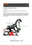
Owners Manual
For All Chainless Bicycle Models
© 2006 Dynamic Bicycles, Inc.
Owner’s Manual
TABLE OF CONTENTS
Chapter 1: Safety First …………………………………………………………………………………………………………… 3
Chapter 2: Assembly Instructions ……….………………………………….…………………………………………………… 4
Chapter 3: Guide to Safe Operation …………………………………………………………………………………………….. 9
Chapter 4: Care and Maintenance …………………………………………………………………………………………….. 12
Chapter 5: Shaft Drive System …………………………………………………………………………………………………. 17
Chapter 6: Troubleshooting ……..……………………………………………………………………………………………… 19
Chapter 7: Limited Bicycle Warranty .…………...……………………… …………………………………………………….. 21
© Copyright 2005
Page 2
Owner’s Manual
CHAPTER 1: SAFETY FIRST
Shaft drive bicycles are designed and assembled to meet the highest safety standards. Shaft drive bicycles also
feature a patented shaft drive system that provides a safe, smooth ride.
Bicycle riding safety also depends greatly on the bicycle operator. Failure to follow these safeguards may result in
damage to the bicycle and/or cause personal injury.
FOR YOUR SAFETY...
•
Always wear a helmet. An unprotected head is highly susceptible to injury, even from the slightest contact, but
wearing a helmet that meets the Consumer Product Safety Commission (CPSC) or CE safety testing
standards may help prevent injury.
•
Make sure that both front and rear brakes are working appropriately. Always use front and rear brakes
simultaneously to stop. Do not use front brake only; using the front brake only increases the risk of being
thrown off the bicycle and injuring yourself when riding downhill or traveling at a high speed.
•
Make regular inspections of your bike. Check to ensure that all nuts, bolts and hardware items (control cables,
forks, pedals, etc) are tightened. Check bicycle frame for any dents or fractures (cracks). Be sure all reflectors
are in place. Replace parts that show wear or damage.
•
Maintain appropriate tire pressure to avoid hazards due to difficulties in steering, braking or pedaling.
•
Do not carry heavy materials or goods. Never carry a passenger on a rear carrier or seated on handlebars, top
tube or any other part of the bike.
•
Avoid riding in heavy rain or snow conditions. Rainy and wet weather conditions require special caution to
ensure safety in turning, accelerating and stopping.
•
Always obey local traffic laws including all traffic signs. When sharing the road with cars, please use caution
and follow all generally accepted rules of the road.
•
Always use proper hand signals for turning and stopping.
•
Rider must be able to straddle bicycle with at least one-inch clearance above the top tube when standing.
•
Do not use the bicycle for stunt riding and/or jumping.
•
Do not use the bicycle for unintended use. Misuse of the bicycle or riding in conditions outside the intended
use of this bicycle can result in serious injury and will void all warranty claims. Intended use is defined as riding
on designated road surfaces, sidewalks, bike paths or approved trails in a smooth manner with both wheels on
the ground.
•
Never ride after consuming alcohol. Bicycle riding requires balance which is impaired if under the influence of
alcohol.
•
Eye protection and appropriate cycling clothes are recommended.
© Copyright 2005
Page 3
Owner’s Manual
CHAPTER 2: ASSEMBLY INSTRUCTIONS
Your new bicycle is 90% factory assembled. The only assembly required is:
•
•
•
•
•
•
Attach Handlebar
Attach Pedals
Attach Front Wheel
Insert Seat Post
Attach Front and Rear Reflectors
Inflate Tires
You will need the following tools for assembly:
•
•
•
•
Cutting tool or knife (for unpacking bike)
Flat head screwdriver
Adjustable pliers or adjustable wrench
4mm,5mm,6mm Allen wrench (included with bike)
ATTACH HANDLEBAR
The handlebar is pre-assembled with brake levers, grips and shifting mechanism attached. All that is required is to
attach the handlebar to the bike or stem. When the handlebar is attached properly, the shifting mechanism will be on
the right hand side. Also be sure that the brake cables and shift mechanism cable are not twisted or wrapped around
stem or handlebar. All cables should extend forward from the bike.
For Bikes Using a Threadless Stem (including Mountain and Road Models):
STEP 1: Using a 5mm Allen wrench, remove the handlebar clamp bolts holding the
front binder to the stem.
STEP 2: Align center of handlebar in stem.
STEP 3: Re-attach the front binder using the clamp bolts. Tighten the two bolts firmly
and evenly so handlebar does not twist or slide when pressure is applied.
NOTE 1: The gap between the stem and handle bar clamp should be the same on
both the top and bottom. This will ensure that the handlebar will not become loose
while riding.
For Bikes Using a Threaded (or Quill) Stem (including Hybrid and Comfort
models):
STEP 1: Insert stem into head tube of frame with handlebars facing forward and all
cables extending forward from the bike as shown.
STEP 2: Set stem at desired height. Be sure stem is not extending out of the head
tube of the frame above the “Minimum Insertion Point” marked on the stem with a
series of small vertical lines.
STEP 3: Remove black rubber cover on the top center of stem and use a 6mm
Allen wrench to tighten the bolt in the top center of stem while keeping the
handlebar facing straight forward.
STEP 4: Replace black rubber cover over stem bolt.
Attaching the Brake Cables (if necessary):
Brake cables extend from the brake levers on the handlebar to the brake arms at each wheel. Inspect each cable to
ensure they are free of any twisting or kinks. If one or both of the cables are not connected, perform the following:
STEP 1: Align the slots on the barrel adjuster and barrel nut with the slot on the break lever.
STEP 2: Slide the circular cable end into the fitting within the break lever. This is seen when the lever is pressed down.
© Copyright 2005
Page 4
Owner’s Manual
The cable should then slide into the slot. The cable
housing ferrule will fit into the barrel adjuster, when
pulled tight.
STEP 3: Twist the barrel nut so that it is firmly
against the lever housing.
ATTACH PEDALS
Although the two pedals supplied with your bike
look the same, they are not. Bicycle pedals are
threaded to match the left and right crank arms of
your bike. The pedals are labeled “L” and “R” on or
near the end of the spindle.
STEP 1: Insert the pedal marked “R” into the right crank (shaft drive
side of bike) and turn the pedal clockwise to tighten.
STEP 2: Tighten securely with a wrench.
STEP 3: Insert the pedal marked “L” in the left crank and turn counterclockwise to tighten.
STEP 4: Tighten securely with a wrench.
ATTACH FRONT WHEEL
To be ridden safely, the front wheel of your bicycle must be firmly attached to the front fork. Most bicycle front wheels
use a quick-release lever-actuated wheel retention mechanism (quick release) that allows the wheel to be installed and
removed without tools. For proper and safe attachment of the front wheel, read and follow these instructions carefully.
STEP 1: Find the quick release mechanism (skewer with lever), which is included in the accessory box with your bike.
STEP 2: Insert quick release skewer through the center of the axle of front wheel, making sure there is one spring on
each side of the axle, with the narrow part of each spring toward the center of the wheel.
STEP 3: Align and insert the front wheel into the dropouts on the front fork (or suspension fork) of the bike, making sure
springs are on the outsides of fork dropouts. Note that it will be necessary to release the front brake cable where it
connects to the brake arm to allow room to insert tire between the brakes. (see Chapter 4 on brake adjustment.)
STEP 4: Adjust the tension of the quick-release by following the procedure below:
A. Move the quick-release lever to the OPEN position (see diagram) and set the wheel so it is straight and firmly
touches the inside of the fork dropouts.
B. With the lever in the OPEN position, tighten the nut on the opposite side of the skewer until finger-tight.
C. Place the lever in the palm of your hand and push the lever to the CLOSED position. At the half-closed position
of the lever, there should be some resistance. If you are unable to fully close the lever, return lever to open position
and loosen adjusting nut just a little and again use palm of hand to push lever to closed position. If lever still does
not close, repeat loosening of adjusting nut little by little until lever closes tightly.
D. Check the attachment. If the lever is moved to the CLOSED position with little or no resistance, clamping
strength is insufficient. Return the lever to the OPEN position, tighten the adjusting nut further and close the lever,
and again test for resistance.
NOTE: Do not tighten the quick-release wheel retention mechanism by turning the lever like a wing nut; it will not
result in sufficient force to hold the wheel in place.
STEP 5: Test that you have properly adjusted and closed the quick-release.
Test For Proper Quick-Release Adjustment
•
Pick up the front of the bike and sharply hit downward on the top of
the front tire. The wheel must not come off, be loose, or move from
side to side.
© Copyright 2005
Page 5
Owner’s Manual
•
•
Make sure the quick-release lever cannot be rotated parallel to the wheel.
When the quick-release is properly tightened and clamped by the lever in the closed position, the clamping
force is adequate to cause metal-into-metal engagement (embossing) of the dropout surfaces.
NOTE: If the quick-release fails any of the above tests, either repeat these adjustment procedures, including these
tests, contact Dynamic Bicycles for assistance, or take your bicycle to local bike dealer for service.
STEP 6: Make sure the wheel is evenly aligned with the frame within the front fork and is evenly spaced between brake
pads and turns freely. See chapter 4 on brake adjustment.
ATTACH SEAT AND SEAT POST
Proper attachment and adjustment of the seat is essential for safe and comfortable riding.
STEP 1: Insert the seat post with the seat attached into the seat
tube of the bike frame with the front of the seat pointed at the
handlebars and aligned with the top tube of bicycle.
STEP 3: Adjust the seat height to an approximate height and use
the quick release clamp to tighten seat post in place.
STEP 4: Apply weight to seat to make sure seat and seat post do
not slide up or down in the seat tube when pressure is applied.
STEP 5: The angle (up and down) and position of the seat (front
to rear) can be adjusted by loosening the Allen bolt on the
underside of the seat using a 6mm Allen wrench.
Adjusting Seat Height
When seated on the bike, put your right heel on the right pedal and rotate the crank to stop the right pedal in its lowest
position (closest to the ground). With this pedal at its lowest position, your heel should touch firmly on the pedal with
your leg straight. If your leg is bent, the seat should be raised; if your heel does not reach the pedal, the seat should be
lowered until your heel rests firmly on the pedal with your leg straight. By doing so, when riding normally with the ball of
your foot on the pedal, you will have comfortable extension throughout the pedal motion with a slight bend in the knee.
NOTE: make sure the seat post is not raised beyond the “minimum insertion point”, indicated by a series of small
vertical lines etched into the seat post. Otherwise, the seat tube could bend and cause injuries.
Adjusting Seat Angle
The seat angle is an often over looked component of comfortable riding. An improper seat angle can lead to soreness
and chaffing. To adjust the seat angle, loosen the 6mm Allen bolt on the underside of the seat clamp. This will loosen
the clamp so that the angle can be adjusted.
ATTACH FRONT AND REAR REFLECTORS
For bikes designed for street riding, the United States Consumer Product
Safety Commission (CPSC) requires that all bicycles have a white reflector
mounted and visible on the front of the bike and red reflector mounted and
visible on the back of the bicycle. To attach the front and rear reflectors:
STEP 1: Identify the white front reflector and mounting hardware included
with your bicycle and mount this reflector to the front fork or handlebar,
depending on your bike model.
STEP 2: Adjust front reflector so it faces forward and tighten screw that
attaches reflector to bicycle.
STEP 3: Identify red rear reflector and mounting hardware included with
your bicycle. Depending on your model of bike and the hardware supplied,
this reflector is mounted either to the seat post, on the top of seat stay, or on rear carrier or fender if equipped. For seat
post installation, loosen the screws, wrap the mounting hardware around the seat post and tighten the screw to secure
© Copyright 2005
Page 6
Owner’s Manual
the reflector in place. It is not necessary to remove seat post to attach red rear reflector. Be sure reflector is facing the
rear of the bike and is clearly visible.
NOTE: Certain bike accessories (such as fenders or baskets) may inhibit the view of the reflectors. Please inspect
reflectors after attaching any accessories.
ADJUST FRONT SUSPENSION
If your bicycle has adjustable front suspension, these adjustments can be performed to meet
your riding preference. These adjustments may include preload (presets compression
stiffness), rebound (sets rate of return spring after shock is compressed) and lock-out (turns
off compression to make fork rigid). It is important to try different suspension settings in a
controlled environment to understand the bikes handing characteristics before riding on or offroad at any suspension setting. Each fork model has different configuration options. Refer to
your fork manual for more information on these settings or contact Dynamic Bicycles.
To Adjust Pre-load on Front Suspension Fork
The most common adjustment for suspension forks is preload adjustment which is typically a
dial on the top of the leg of the fork. Setting the fork for more travel (softer ride) provides a
smoother ride by moving up and down more freely across uneven terrain; but requires care
when applying the brakes, and may compress when pedaling hard. Less travel (stiffer ride)
provides a rougher ride, but may provide better control when braking.
STEP 1: Standing over your bike facing forwards, look down at the top of your suspension forks. At the top of one or
both of the forks is a black dial. Turning the dial clockwise tightens (less travel) the suspension, and turning the dial
counterclockwise loosens (more travel) the suspension.
STEP 2: Set dial to desired tension.
STEP 3: Test suspension resistance and travel by pushing downward on the front handlebar while applying the front
brake.
INFLATE TIRES
Inflating and maintaining proper tire pressure is critical to safe operation
and ensuring maximum longevity of a tire’s use. Inflate your tires to the air
pressure recommended on the tire sidewalls (i.e. 40-65 PSI or 60-85 PSI).
Tires offer a range of inflation. When inflating a tire, consider the weight of
the rider (and any load). Within the range, higher pressure usually gives
the best performance on hard surfaces like pavement, while lower
pressure works best for off-road riding. Use a tire gauge to check tire
pressure before each ride, as changes in air temperature and riding
conditions can affect tire pressure.
© Copyright 2005
Page 7
Owner’s Manual
ATTACH ACCESSORIES
Kickstand
Your bike or may not have been supplied with a kickstand. Choosing whether or not to use your kickstand is a personal
preference.
NOTICE: Kickstands should be used with caution, particularly when riding off-road. Kickstands can be damaged or
interfere with normal riding if they are jarred loose or are knocked into your bicycle. In severe instances, the kickstand
could come into contact with your moving wheel, potentially causing the rear wheel to lock up by jamming between the
spokes. It is not recommended to use a kickstand when riding off-road.
Rear Carrier
Rear carriers can easily be attached to your bicycle. There are many kinds of carriers
available, each with different means of attachment. Some carriers attach to the seat post
only, while others attach to the frame (usually to the seat stay tube and rear dropouts).
Please refer to the instructions that accompanied your carrier for attachment
instructions, or contact Dynamic Bicycles.
Handlebar Risers (Bar Ends)
Handlebar risers are extensions added to your handlebars to aid in climbing hills.
NOTE: Adding bar ends will require you to cut and permanently shorten your handlebar
grips. If at a later time, you choose to remove these bar ends, new grips may be required.
To add bar ends to bicycle handlebars:
STEP 1: Use an Allen wrench to loosen brake lever attachments on both sides of
handlebars.
STEP 2: Use an Allen wrench to loosen grip shift attachment.
STEP 3: Cut tip off end of grip on each side of handlebar.
STEP 4: Slide brake lever attachments, grip shift mechanism and grips inward on handlebars approximately 1/2" to 1”
to make room for bar end.
STEP 5: Slide bar end onto to outside end of handlebar. Tighten bar end securely to handlebar.
STEP 6: Use caps to cover exposed ends of handlebar tubes (if applicable).
NOTE: If you are unable to slide grip shifts inward, cut approximately 1/2” – 1” off end of grip on each end of handlebar
– just enough to slide the bar end onto the end of the handlebar. Attach bar end to outside end of handlebar. Tighten
bar end securely to handlebar. If necessary, use caps to cover exposed ends of handlebar tubes.
Toe Clips
Toe clips are used to keep your feet on pedals while riding, and help to maximize pedal power
throughout the pedal motion. Toe clips are attached to pedals so your foot can slide into the
basket when placed on the pedal. Straps are used to secure the toe clip to the pedal and tighten
the toe clip around your foot. NOTE: Be sure toe clip and strap are not too tight. Your foot must
be able to slide easily out of the toe clip.
Water Bottle Cage
Your bicycle is equipped with pre-drilled holes on the downtube and/or seat tube for attaching a
water bottle cage. To attach this cage, align the mounting holes of the bottle cage with predrilled holes on the downtube, and use the screws included with your bottle cage to securely
attach the bottle cage to the bicycle. NOTE: Be sure the bottle cage does not interfere with any
moving parts of the bicycle or interfere with your normal operation of the bicycle.
© Copyright 2005
Page 8
Owner’s Manual
CHAPTER 3: GUIDE TO SAFE OPERATION
GET TO KNOW YOUR BIKE
The better you understand your bike, the better you can understand how to safely operate and maintain it. The picture
below identifies some of the key components of your bike.
MAKE SURE YOUR BICYCLE FITS YOU PROPERLY
Make sure there is adequate top tube clearance. There should be at least one inch
(25mm) of clearance between the top tube and the crotch of the rider when standing over
the bicycle. For mountain bikes, two inches (50mm) of clearance is recommended.
If you are not sure your bike frame is the right size for you, or if you feel you need a
different size frame, please contact Dynamic Bicycles for assistance.
BEFORE EACH RIDE
Before each ride, check your bike using the checklist below:
•
•
•
•
•
•
•
•
Check your helmet and adjust strap. Always wear a helmet when riding!
Check attachment of both wheels and ensure the wheels are straight and spin freely between the brake pads.
Check your tire inflation.
Check your brakes to be sure brake pads are properly aligned to wheel rim and not in need of replacement.
Also be sure brake lever is properly adjusted (see section above on brake adjustment).
Check (and adjust as necessary) the shifting mechanism.
Check your handlebars, stem and bike frame for signs of stress or fatigue. This includes cracks, dents,
deformation, or discoloration. If any part shows signs of damage or fatigue, replace the part before riding the
bicycle.
Check for loose screws, nuts and bolts and other parts, such as cranks, shifter, brakes and control cables.
Clean (and lubricate as necessary) all moving parts that are exposed to the elements such as the grip shift
lever, shift control cables, brakes control cables, pedals, front and rear shaft drive housing.
© Copyright 2005
Page 9
Owner’s Manual
OPERATING SHAFT DRIVE GEARS WITH GRIP SHIFT
Shifting with internal gears is simply a matter of twisting the shifter to the
indicated position for the desired gear. Before you have twisted the shifter to
the gear position of your choice, ease the pressure on the pedals for an instant
to allow the hub to complete the shift. When shifting gears, plan ahead. If you
shift while pedaling, reduce your pressure on the pedals. Excessive
tension on gears makes shifting difficult and speeds the wear of the
components. Choose the gear most comfortable for riding conditions. You
should be able to maintain a constant rate of pedaling. It should be noted that
you do not have to pedaling to shift using the NEXUS internal gear hub.
Which gear should I be in?
The numerically lowest gear (1) is the easiest to pedal and is intended for climbing hills. The numerically largest gear is
for the greatest speed. Shifting from an easier, “slower” gear (like 1) to a harder, “faster” gear (like 2 or 3) is called an
upshift. Shifting from a harder, “faster” gear (like 7) to an easier, “slower” gear (like 6 or 5) is called a downshift. It is not
necessary to shift gears in sequence. From a stop, select the best “starting gear” for the conditions — a gear which is
hard enough for quick acceleration but easy enough to let you start pedaling without straining. Experiment with
upshifting and downshifting to get a feel for the different gears. One of the unique capabilities of an internal gear
system is that, unlike chain systems, you can change gears while riding or standing still, making it easy to always be in
the right gear.
PRACTICE RIDING YOUR NEW BICYCLE
The features of your bicycle, particularly the shaft drive and rear hub gearing, operate differently than a chain and
derailleur system. These features give you better comfort and control, but they also take practice before you can
achieve proficiency. Practice at slow speeds first. Before riding fast or in more difficult conditions, practice shifting and
learn the function and performance of your shaft drive bike by riding where there are no obstacles, hazards or other
traffic, until you’ve built up your confidence. Gain comfort with the bike’s handling and responsiveness before riding on
roads or trails.
SHARING THE ROAD
•
•
•
•
•
•
•
•
•
•
•
•
•
Wear protective clothing including helmet, eye protection, and gloves. Always wear a helmet when riding!
When sharing the road with automobiles, ride defensively. To motorists, pedestrians, or other bicyclists, you are
not as visible as a car. Always watch for hazardous situations, and be ready to stop or take evasive action at all
times.
Use proper hand signals.
Ride single file when riding with other cyclists.
Ride on the correct side of the road; never go against traffic.
Do not ride ‘no hands’; the slightest road imperfection could initiate a wheel shimmy, or cause the front wheel
to turn unexpectedly.
Do not ride with loose objects attached to the handlebars, or any other part of the bicycle. They could get
caught in the wheel spokes, cause the handlebars to turn unexpectedly, or in other ways cause loss of control.
Do not ‘ride double’. Standard bicycles are not designed to carry the additional load of a second rider. Also,
extra weight makes a bicycle much harder to balance, steer and stop.
Watch for, and avoid, potholes, drain grates, soft or low shoulders, and other deviations which could cause
your wheels to slip or create an impact. When crossing railroad tracks or drain grates, do so carefully at a 90°
angle. If you are not sure of riding surface conditions, walk your bike.
Watch the cars you are preparing to pass.
If a car suddenly enters your lane, or someone unexpectedly opens the door of a parked car, you could be
involved in a serious accident. Mount a horn or bell on your bicycle, or carry a whistle and use it to alert others
of your presence.
Be careful when riding in low light conditions.
Your bicycle is equipped with a full set of reflectors; keep them clean and in position. As useful as these
reflectors are, they do not help you see, nor do they help you be seen unless light is directed on them. Use a
working headlight and tail light when you ride in poorly lighted or low visibility conditions.
© Copyright 2005
Page 10
Owner’s Manual
•
•
Also wear light, bright, and reflective clothing, especially at night, to make yourself more visible. The important
thing is to see and be seen. If you do any amount of riding at dusk, at night, or in any poorly lighted conditions,
consult your local bicycle dealer to find appropriate products to aid your vision and make you more visible.
Understand the “Rules of the Road” in your area. In many states, bicycles are subject to the same traffic laws
as automobiles.
RIDING OFF-ROAD
•
•
•
•
•
•
•
•
Wear protective clothing including helmet, eye protection, and gloves. Always wear a helmet when riding!
Ride only on marked trails.
Never ride a road or touring bike on, trails, or off-road.
When approaching a descent, reduce your speed, keep your weight back and low, and use the rear brake
more than the front.
Avoid undue stress to your bicycle. Bicycles are not indestructible: as with anything mechanical, every part of a
bicycle has a limited useful life due to wear, stress, and fatigue. Fatigue refers to a low-stress force that, when
repeated over a large number of cycles, can cause a material to fail or break. The length of the life of a part
varies according to its design, materials, use, and maintenance. Although lighter frames or parts may, in some
cases, have a longer life than heavier ones, it should be expected that light weight, high performance bicycles
and parts require better care and more frequent inspections. Regularly inspect your entire bicycle for signs of
fatigue or stress:
• Dents
• Cracks
• Scratches
• Deformation
• Discoloration
Fatigue can be accelerated by large forces from unsafe riding practices such as:
• Jumping your bicycle
• Performing bicycle stunts
• Severe off-road riding
• Downhill riding
• Any abnormal bike riding
Carefully inspect your frame and components for signs of fatigue before and after each ride.
Even if you perform regular inspections, if you exceed the limit of strength of your bicycle or a given part, it will
fail.
© Copyright 2005
Page 11
Owner’s Manual
CHAPTER 4: CARE AND MAINTENANCE
Although your bike is designed to require little maintenance, routine inspections and adjustments and lubrication should
be performed to ensure your safety and sustain peak performance of the bike.
ROUTINE MAINTENANCE
Routine inspections and adjustments are fast and easy, and should be performed before each ride. Below is a list of
items to check before each ride:
•
•
•
•
•
•
•
•
•
Check that your wheels are straight and spin freely between brake pads.
Check your tire inflation.
Check your brakes to be sure brake pads are properly aligned to wheel rim and not in need of replacement.
Also be sure brake lever is properly adjusted (see section above on brake adjustment).
Check (and adjust as necessary) the shifting mechanism.
Check attachment of both wheels.
Check your handlebars, stem and bike frame for signs of stress or fatigue. This includes cracks, dents,
deformation, or discoloration. If any part shows signs of damage or fatigue, replace the part before riding the
bicycle.
Check your suspension adjustment.
Check for and tighten any loose screws, nuts and bolts and other parts, such as cranks, shifter, brakes and
control cables.
Clean (and lubricate as necessary) all moving parts that are exposed to the elements such as the grip shift
lever, shift control cables, brake control cables, pedals, front and rear shaft drive housing.
Test and Adjust Brakes
If your bicycle is equipped with linear pull or caliper brakes on the front and rear tires, when brake lever is in its fully
extended position, tire rims should rotate freely between the brake pads without any rubbing. When the brake lever is
squeezed halfway to handlebar, brake pads should close tightly on the wheel rim. The brake lever should not touch the
handlebar when applying the brake.
If your bike is equipped with disc brakes, when brake lever is in its fully extended position, the disc brake rotor should
rotate freely between the brake pads without any rubbing. When brake lever is squeezed halfway to handlebar, brake
pads should close tightly on the disc rotor. The brake lever should not touch the handlebar when applying the brake.
Note: Brake cables will invariably stretch out over time, resulting in the
need to squeeze the lever further to operate the brakes. Adjusting the
brakes to compensate for this cable stretch can be done easily,
however it is recommended that the brake cables be inspected and
replaced periodically by a bike shop to ensure optimum safety and
performance.
Barrel Adjuster
Lock Nut
Part A: Barrel Adjustment
The barrel adjustment can be used to either tighten or loosen the
brakes. This adjustment however does not center the brake pads.
When applying the barrel adjustment, you may be required to re-center
the brakes, which is described in part B.
Step 1: To tighten the brakes, first loosen the lock nut on the barrel
Figure 1: Brake lever, with barrel adjuster
adjuster. (See Figure 1) Then turn the barrel away from you (same
and lock nut shown.
direction the tires move on the bike when the bike is in motion). The
brake pads should engage the rim when the lever is at least at its half way point. Retighten the lock nut against the
lever housing.
Step 2: To loosen the brakes, first loosen the lock nut on the barrel adjuster. Then turn the barrel towards you
(opposite the direction the tires turn when the bike is in motion). The brake pads should engage the rim when the lever
is at least at its half way point. Retighten the lock nut against the lever housing.
© Copyright 2005
Page 12
Owner’s Manual
Part B: Centering the brakes:
Centering the brakes is accomplished by tightening or loosening the
rebound adjustment screws located at the base of both brake arms.
(Small Phillips head screw) This screw can take both Philips and Flat
head screw drivers. (See figure 2).
Step 1: Looking at the brakes observe which pad is closer to the rim. It is
also recommended to spin the wheel to determine which side is always
the closest (many wheels have a slight but allowable “wobble” in the rim).
The pad that is the closest to the rim is the pad that needs to be moved
away from the rim.
Adjustment screw
Step 2: To move the pad away from the rim, tighten the corresponding
screw on that side of the rim by turning the screw clockwise. Tighten
Figure 2: Base of brake arm with adjustment
screw 1/2 turn at a time and recheck after every adjustment by squeezing screw shown.
the brake lever and spinning the wheel to set the brakes in their new
position. A spacing of 2mm or closer is recommended between both brake pads. (See Figure 3)
Step 3: If you are unable to move the brake pad to the desired position by
tightening the adjustment screw, loosen the screw on the opposite arm.
Loosen this screw 1/2 turn at a time and squeeze the brake lever to reset
brakes and spin the wheel to recheck.
2mm space
between pad
and rim
Part C: Brake pad positioning:
Brakes on your Dynamic bicycle will already have been adjusted. In the
event that you need to replace brake pads, or for some other reason the
pads are not correctly positioned on the rim, you will have to re-align the
pad.
Step 1: Loosen the 5mm Allen bolt that holds the brake pad in place. It is
important to make sure the pad is not touching the rim.
Figure 3: Brake assembly, with rim and
brake pad clearance depicted.
Step 2: Position the brake pad so it is centered on the rim and is not
touching the tire (some brake pads also use an arrow to show direction of tire rotation and/or have a curvature to the
pad to match the curve of the rim). Squeeze the brake arm so the pad is tightly against the rim and re-tighten the 5mm
Allen bolt. It is important to make sure the pad does not rotate while you are tightening the bolt. (see Figure 3)
NOTE: The straightness of the rim also plays an important role in brake performance. If the rim “wobbles” when
rotating more than 3mm side to side this will greatly affect the performance of the brakes. A rim can easily be
straightened (trued) at your local bike shop.
Maintenance of Shaft Drive Transmission System
The shaft drive transmission system is an integral part of your bicycle. The life of a shaft drive and gears depends on
two factors: 1) how the bike is operated, and 2) how well it is maintained. Periodically check your shaft drive and follow
a regular maintenance schedule:
•
•
Make sure the left and right covers of the front gearbox are properly tightened. Otherwise the front gearbox
could produce noise and shorten the life of a shaft drive.
Add grease every three months of heavy riding, or every six months of regular riding, or every 12 months of
occasional riding. To apply grease to front gearbox, turn bike over and use a grease gun and the grease-nipple
(Zurk fitting) equipped under the front housing (clean the nipple first) to apply grease into the front gearbox. For
a typical grease gun, two squirts of grease are sufficient. Most common automotive grease guns will fit the
nipple. To apply grease to the rear gearbox, remove the screws and black cover on the rear gearbox and
squeeze grease on to gears. You only want to use enough grease to reduce friction between gears. Do not
attempt to fill up gearboxes with grease.
© Copyright 2005
Page 13
Owner’s Manual
NOTE: There are many varieties of grease available. Recommended grease type is gear grease used to pack
bearings and lubricate gears or joints and is rated for use between -10° F and 140° F, and can be found at any
local bike shop. The grease you choose needs to be thick to create and maintain a protective film between the
interlaced bevel gears. Do not use oil or liquid lubricant as this will not adequately lubricate gears.
How to Remove the Rear Tire for Repair or Replacement
1. Put the bike into 4th gear.
2. Detach the brakes by pinching the brake arms and
releasing the brake cable from the swing arm bracket on
the opposing brake arm (Figure 1).
3. Slide off the black dustcover (Figure 2) by first removing
the two small Phillips head screws. The dustcover may be
tight.
4. Loosen the two lug nuts found on either side of the rear
axle using an adjustable wrench, or 15mm wrench.
5. Slide the wheel off the horizontal drop outs.
6. Remove the cable from the cassette joint pulley, by pulling
the cable housing out of the cable arm. (Figure 3) You
need to be in a low gear to do this. Slide the pinch nut out
of the slot on the cassette joint pulley (Figure 4). You may
have to wiggle the pinch nut in order for it to release.
Figure 1: Releasing the brakes.
Figure 2: Removing the dust cover.
Figure 3: Releasing the cable.
Figure 4: Remove pinchnut from slot.
© Copyright 2005
Page 14
Owner’s Manual
Installing the rear wheel
1. First re-attach the cable to the cassette joint pulley by placing
the pinch nut into the slot in the cassette joint pulley (Figure
4). Make sure that the black side of the lock nut is facing
away from the hub. It is helpful to have the wheel partially on
the drop outs to do this.
2. Rout the cable back into the groove of the cassette joint
pulley. The cable should wrap around the cassette joint
pulley in a counter clockwise direction (Figure 5) such that it
is to the inside (closer to the hub) of the tabs with the colored
dots (red or yellow).
3. As shown in Figure 3, pull on the cable housing (there will be
tension on it) to place the silver metal feral cap at the end of
the shifter cable back into the arm of the cassette joint
pulley.
4. Slide the rear wheel back onto the drop outs.
5. Tighten lug nuts right side of rear axle. It is very important
to retighten the right side first, then tighten the left side.
When tightening the lug nuts hold the cassette joint pulley
arm in a forward position (leaning towards front of bike), as
it has a tendency to rotate backwards.
7. Re-attach the black dust cover
8. Re-attach brake cable to brake arms by reversing the step
you did when releasing the brake arms (Figure 1).
9. You are now ready to ride.
Figure 4: Insert pinchnut into slot on cassette
joint pulley.
Figure 5: Route cable around cassette joint
pulley behind tabs with colored dots (red or
yellow).
© Copyright 2005
Page 15
Owner’s Manual
MAINTENANCE OF INTERNAL REAR HUBS
The internal rear hub on your bicycle is self-lubricating. It was designed
to last for many years with minimal maintenance and adjustment. If the
gears slip, check the gear shifting mechanism and make sure gears
are appropriately adjusted.
ADJUSTMENT OF GEARS
Internal Rear Hubs and Gear Shifting
The gear-shifting mechanism is pre-adjusted at the factory. Shifting
gears is simple and easy. However, Shimano recommends that you
ease-up your pedaling force (or pause) when changing gears. Full
force should be avoided in pedaling when changing gears because of
the construction of the internal gear shifting mechanism. If gears are
not locked into place, gears could slip and full force pedaling could
damage internal hub gears.
Adjustment of Shimano 7-Speed and 8-Speed Gear Shifting
If gears slip, it is important that you read the instruction manual carefully and make sure the gear shifting mechanism is
adjusted properly.
STEP 1: Using a flat head or Phillips head screwdriver, remove the screws on the rear gearbox cover and remove the
black plastic dust cover by sliding it backwards off the bike.
STEP 2: Turn the shift lever to 4th gear.
STEP 3: On the 7-speed bikes, look for two red dots - one on the cassette joint bracket and one on the cassette joint
pulley. Check to see whether the two red dots on the cassette joint bracket and pulley are aligned.
On the 8-speed bikes, look for a yellow dot and green dot. Check to see whether these two colored dots on the
cassette joint bracket and pulley are aligned. In 4th gear
STEP 4: If the colored dots are not aligned in 4th gear, turn the barrel
adjustment nut located where the shifter lever on the handlebar meets
the shifter cable. Turn this barrel adjustment nut clockwise or counter
clockwise to align the two colored dots.
STEP 5: Turn the gear shifter from 4th to 1st gear and then back to 4th
gear to double-check to make sure the colored dots are still aligned.
MAINTAINING FRONT SUSPENSION FORKS
The biggest threat to a suspension fork is contamination, which is preventable with regular cleaning and lubrication.
You should regularly clean and lubricate the fork legs and upper seal.
To clean and lubricate front fork: Remove any dirt using a soft, damp cloth. Lubricate the upper seals and stanchion
(part of fork that moves up and down inside leg of fork) with a non-Teflon based wet lubrication. Wipe off excess so it
doesn't attract dirt that can contaminate the fork internals.
MONITOR TIRE WEAR
Tires will wear over time. Tire wear and tire pressure will vary according to frequency of usage, terrain, and air
temperature. Generally, tires will need replacing when:
•
•
•
A bulge is noticeable
Little or no tread remains
Damage (including cracking or tearing of rubber) to tread or sidewall is apparent
Riding a bicycle with under-inflated tires may cause damage to the tube, tire and rim. Check tire pressure regularly to
keep tire within pressure range indicated on sidewall of tire.
© Copyright 2005
Page 16
Owner’s Manual
CHAPTER 5: SHAFT DRIVE SYSTEM
The shaft drive is a patented,
lightweight and rugged aluminum
alloy bevel gear drive system. This
“chainless” drive system provides
smooth, quite and efficient transfer
of energy from the pedals to the
rear wheel. The shaft drive is
designed and manufactured using
the highest quality parts to last for
many years.
The shaft drive is combined with a multi-speed internal rear gear hub to provide a wide range of gearing for many types
of terrain – from city streets to suburban paths to mountain trails.
With the shaft drive, all moving parts are fully enclosed. The spiral bevel gears used in both the front and rear gearbox
are precision made using a machine cut, heat-treated, hardened chromoly. These gears are in a fixed position and do
not need adjustment or maintenance. These gears are lubricated using standard thick bicycle grease, similar to what is
used to pack bearings. The front gearbox is equipped with a Zurk fitting for easy lubrication. The rear gearbox has a
removable dust cover that provides direct access to the gears for easy lubrication. The bearings used in the shaft are
all sealed and lubricated and do not require maintenance. The shaft rod is a solid steel rod, attached at both ends to
the bevel gears.
IDENTIFICATION OF SHAFT DRIVE COMPONENTS
Identification of the shaft drive transmission system components is displayed in the following illustration.
© Copyright 2005
Page 17
Owner’s Manual
PARTS SPECIFICATION TABLE
This table details the components
of the shaft drive transmission
system.
© Copyright 2005
No
1
2
3
4
5
6
7
8
9
10
11
12
13
14
15
16
17
18
19
20
21
22
23
24
25
26
27
28
29
30
Name
Bottom Bracket Shell
Front Gearbox
Right Cover
Left Cover
Front Stand
Rear Stand
Rear Gear Box
Transmission Tube
Crank Axle / Spindle
Transmission Axle - Shaft
Crank Gear
Front Transmission Gear
Rear Transmission Gear
Hub Gear
Right Dropout
Left Dropout
Washer(s) for spacing gears
Rear Gearbox
Bearing 6203 (F. S. gear/right cover)
Bearing 6003 (F. S. gear/left cover)
Screws for front/rear stands
Screws for left cover
Screws for rear gearbox
Screws for ends of transaxle
Screw for rear gearbox cover
Flat Washers
Spring washers
Rear Gearbox Cover (Dust Cap)
Hub gear circlip
Grease nipple
Specification
Aluminum
Aluminum Alloy
Aluminum Alloy
Aluminum Alloy
Aluminum Alloy
Aluminum Alloy
Aluminum Alloy
Aluminum Alloy
Cromoly
Carbon Steel
Cromoly
Cromoly
Cromoly
Cromoly
Aluminum
Aluminum
0.2mm/1mm
Aluminum Alloy
Sealed
Sealed
Inner Hexagon M5 x P.8 x 12
Inner Hexagon M6 x P.8 x 20
Outer Hexagon M6 x P1 x 16
Outer Hexagon M6 x P1 x 10
Taping M4 x 20
6.4T =1.6mm
6.1T = 1.5mm
PVC
Steel
Unit
1
1
1
1
1
1
1
1
1
1
1
1
1
1
1
1
1
3
2
3
8
3
2
2
2
4
4
1
1
1
Page 18
Owner’s Manual
CHAPTER 6: TROUBLESHOOTING
Below are answers to some common questions regarding your bicycle. If you have questions or concerns about your
bicycle that are not covered in this manual, please contact your reseller or distributor.
Symptom
Roughness or Noise from
the Front Gearbox
Rear Wheel Will Not Turn
Handlebar is Not High
Enough or Too High
© Copyright 2005
Solution
1. First, check all screws, nuts and bolts of the shaft drive system to see
whether they are properly tightened and whether the rear wheel is loose.
Tighten all screws and nuts.
2. If front gears turn smoothly when you turn the pedals with your hand, the
noise may be due to lack of grease. Turn the bike upside down and use a
grease gun and the equipped grease-nipple to lubricate the gears inside
the front and rear gearbox. For best lubrication, we recommend using a
high quality gear, joint or bearing grease rated for -10° F to 140° F
temperature range. The grease you use should be thick, similar to the
grease used to pack bearings; the grease needs to create a protective
layer between the gear teeth. Do not use oil or liquid lubricants. If the
roughness or noise is persistent, please contact Dynamic Bicycles for
assistance.
3. If the gears turn roughly at a particular point on each rotation, it is
possible either the left side or right side bearing is damaged or one the
teeth of the bevel gears is damaged. Contact Dynamic Bicycles for
assistance.
4. Try removing the rear wheel and check the shaft drive for smoothness
without the wheel. If shaft is smooth in your hand without the rear wheel
attached, but is still rough when riding, this may be due to the hub. Please
contact Dynamic Bicycles for assistance.
1. The rear hub gear and transmission gear are not correctly meshed.
Loosen the rear wheel and make sure rear gears are mesh snugly. Be
sure spacing washers on the inside of the rear gearbox of the shaft drive
are in place.
2. If rear wheel will not turn in 1st gear only, this may be due to a
malfunction of the cassette joint pulley and may need an adjustment or
replacement to of one of the three layers of the cassette joint pulley.
Contact Dynamic Bicycles for assistance.
1. On many bike models, the bike is equipped with an angle adjustable stem
and/or a quill style stem. Look on the underside of the stem (connects the
handlebar to bike). If you see and Allen bolt, you can loosen this Allen bolt
and rotate the stem higher or lower to suit your riding preference, then retighten this Allen bolt.
2. To raise the height of the stem, check to see if your stem slides up and
down inside the head tube of the frame. If it does, this stem can be raised
up or down to suit your riding preference by loosening the Allen bolt on
the top center of the stem. Raise or lower stem to desired position and
retighten this Allen bolt, making sure handlebar is facing straight forward.
Page 19
Owner’s Manual
Gears Do Not Engage or
Gears Slip
Shifting mechanism is out of alignment due to improper cable tension.
Adjustment of Shimano 7-Speed and 8-Speed Gear Shifting
If gears slip, it is important that
you read the instruction
manual carefully and make
sure the gear shifting
mechanism is adjusted
properly.
Noise From Rear; Rotation
not Smooth
Gear Has A Lot of
Resistance in Extreme Cold
Weather
© Copyright 2005
STEP 1: Using a flat head or
Phillips head screwdriver,
remove the screws on the rear
gearbox cover and remove the
black plastic dust cover by
sliding it backwards off the
bike.
STEP 2: Turn the shift lever to
4th gear.
STEP 3: On the 7-speed
bikes, look for two red dots one on the cassette joint
bracket and one on the
cassette joint pulley. Check to
see whether the two red dots on the cassette joint bracket and pulley are
aligned.
On the 8-speed bikes, look for a yellow dot and green dot. Check to see
whether these two colored dots on the cassette joint bracket and pulley are
aligned. In 4th gear
STEP 4: If the colored dots are not aligned in 4th gear, turn the barrel
adjustment nut located where the shifter lever on the handlebar meets the
shifter cable. Turn this barrel
adjustment nut clockwise or counter
clockwise to align the two colored
dots.
STEP 5: Turn the gear shifter from
4th to 1st gear and then back to 4th
gear to double-check to make sure
the colored dots are still aligned.
1. Check to make sure that the spacing washers on the inside of the rear
gearbox of the shaft drive are in place. If they are not, the gears may not
mesh smoothly, causing a roughness.
1. Don’t ride if in extreme cold weather since grease might have been
frozen. Bring bicycle indoors and allow parts to return to room
temperature.
Page 20
Owner’s Manual
CHAPTER 7: LIMITED BICYCLE WARRANTY
WHAT DOES THE WARRANTY COVER?
1. The drive shaft transmission system and Shimano hub are guaranteed for two (2) years from original date of
purchase for the original owner
2. The frame is guaranteed for life for the original owner.
3. All other components are guaranteed for one (1) year from original date of purchase for the original owner.
This warranty is contingent upon the fact that your bicycle was properly assembled, maintained and operated under
normal conditions and for its intended use, and that you submitted a registration and warranty card. This warranty shall
be limited to the repair or replacement of parts and does not include shipping charges or any labor charges to repair or
replace defective parts. This limited warranty is made only to the original owner and is not transferable. All claims must
be made directly to Dynamic Bicycles or through an authorized dealer and accompanied by original dated sales receipt
(as proof of purchase) and/or proof of product registration.
The original owner is responsible for any and all shipping, labor and transportation charges associated with the repair
or replacement of all parts under this warranty.
INTENDED USE
Intended use of our bicycle is defined as riding in a controlled, smooth manner in a location approved for bicycles with
both wheels on the ground. Riding in a manner other than this voids the manufacturers warranty and bicycle operator
assumes all liability for injuries or damage as a result.
WHAT DOES THE WARRANTY NOT COVER?
•
•
•
•
•
•
•
•
•
Fair wear and tear on all components of the bicycle and shaft drive system
Misuse of the bicycle
Hiring out or renting of the bicycle or any commercial use
Racing the bicycle in events
Stunt riding or jumping
Modifications made to the bicycle other than adding accessories
Accidental damage both from on and off road riding
Damage caused by accidents or vandalism
Unintended use of the bicycles
This warranty does not cover any failures, operating difficulties due to abuse, misuse, alteration, misapplication,
vandalism, improper installation or failure to perform normal or routine service. The manufacturer is not responsible for
injury or damage caused by improper completion of assembly or improper maintenance.
DISCLAIMER
These are the only guarantees under the terms of this warranty. The sole and exclusive liability of the authorized
distributors, dealers, affiliates or the agent pursuant to this warranty shall be for the repair and replacement of the
defective parts. This warranty does not cover incidental and consequential damages or by any implied warranty,
including but not limited to loss of use or inconvenience.
This warranty is the only express warranty made. Any other warranties which may be implied by law, including but not
limited to any warranties of merchantability or fitness for a particular purpose are limited to the same duration shown
above.
Some states in the United States do not allow limitation on how long an implied warranty lasts, and/or the exclusion or
limitation of incidental or consequential damages, so the above limitations and exclusions may not apply to you. This
warranty gives you specific legal rights, and you may also have other rights, which vary depending on state, province,
or country where you purchase this bicycle.
© Copyright 2005
Page 21
Owner’s Manual
NOTICE
Bicycling is a potentially hazardous activity. The user assumes the risk of any personal injury, damage to or failure of
the bicycle and any other losses if the bicycle is used contrary to their intended use, in any competitive event including
bicycle racing, dirt biking, jumping or similar activities or training for such competitive activities or events.
Shaft drive bicycles are not manufactured or intended to be altered for use at any time for stunt riding or similar
activities. Your shaft drive bicycle manufacturer, distributor, dealer, affiliates or agents shall not be liable under this
warranty nor under any state or federal law or common law or otherwise for any damage, failure, including personal
injury, resulting from such use.
© Copyright 2005
Page 22
Owner’s Manual
Dynamic Bicycles, Inc.
Phone: 1-800-935-9553
Website: www.dynamicbicycles.com
Email: [email protected]
© Copyright 2005
Page 23