1
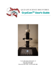
National Optical & Scientific Instruments Inc.
11113 Landmark 35 Drive
San Antonio, Texas 78233
Phone (210) 590-9010 Fax (210) 590-1104
INSTRUCTIONS FOR
MODEL DC5-163
COMPOUND BIOLOGICAL MICROSCOPE
WITH DIGITAL CAMERA
(For microscope operation only. Camera operation and installation covered in separate
supplement to documentation)
HOW TO USE YOUR MICROSCOPE SERIAL NUMBERS
1. Microscope serial number: This number (etched on back arm of microscope) is the
number under which your warranty is registered.
2. Microscope DM number: This number (found on a white sticker on the bottom of the
microscope) is used for logging on the Motic web site, which gives you the ability to
download free software upgrades.
3. Motic CD DM number: This number is to be used to register the software when
loaded on the computer for the first time.
Copyright © 8/5/04
National Optical & Scientific Instrument Inc.
Eyepiece
LED indicator light
Sliding interpupillary adjustment
grips located on both left and
right side of diopter scale
Interpupillary
scale
Three position sliding rod
Viewing head of
microscope
Mark on side of eyepiece tube
for indexing diopter reading
Revolving nosepiece
Arm
Objective lenses
Knurled locking screws
(for securing specimen
Specimen holder
holder to stage)
(mechanical stage)
Abbe condenser
locking screw
Stage
Abbe condenser 1.25 N.A.
Coarse focus
knob
Iris diaphragm lever
Fine focus
knob
Filter holder
Control knob for
Abbe condenser
Knobs controlling X
and Y movement of
mechanical stage
Illuminator condenser
Base
Light intensity
control knob
Detachable power supply cord
100v-240v, 50H/60H input
Power
On/Off
Main Camera
Switch On/Off
12 volt
DC output
Tension
adjustment knob
12 volt
DC input
USB output
terminal
12 volt DC switching power supply
About the Digital Microscope
The manual for your new digital microscope is in three parts. This first part describes the basic nomenclature and
functions of the microscope, which can be used as a fully functional microscope, independent of the camera. The
second part is the “Important Supplement to Documentation” describing loading of your CD. The third part is the Motic
Images Quick Start Guide located on your CD, which provides detailed documentation for installation and operation of
the Motic Images software. In order to achieve optimum results, it is important that you carefully read these
documentation manuals before operating your microscope or camera.
UNPACKING
1. Your microscope is packed with the following components, all of which have been checked at the factory.
Carefully remove all components and check against this list. Retain styrofoam container in case microscope must
be transported or returned to factory for any reason.
A.
B.
C.
D.
E.
F.
G.
H.
I.
J.
K.
L.
M.
N.
O.
Microscope body with 1.25 N.A. Abbe condenser and iris diaphragm
Two WF10x eyepieces
Two rubber eyecups
Four objective lenses: DIN 4x, 10x, 40xR, 100xR oil immersion
Three filters: blue, green, yellow
Specimen holder for mechanical stage
12VDC switching power supply, operates on 100v-240v, 50H/60H
Power cord
CD Motic Images software
Two instruction manuals: this one and separate supplement documentation
Calibration slide
USB 2.0 PCI card with driver CD and user manual
USB cable (for connecting to computer)
Dustcover
Warranty card
2. If it becomes necessary to ship the microscope for any reason, repack it in the styrofoam container, and then pack
the styrofoam in another corrugated shipping container for optimum protection. Use of the styrofoam alone will not
provide adequate protection in transit, and will void your warranty.
A. NOTICE: To protect focus mechanism during shipment, two black plastic wedges (b) and one black plastic
block (c) are inserted at strategic points as indicated. These plastic parts MUST be removed prior to operating
microscope. Failure to do so will result in damage to focusing mechanism and will void your warranty.
(a)
1. Remove two black velcro straps (a).
2. Remove wedge (b) by pulling apart the
two parts of wedge in opposite directions.
3. Lower stage by rotating coarse focus
knob in counter-clockwise direction.
in counter-clockwise direction
4. Remove block (c) from stand.
5. These components should be retained
with styrofoam container.
(c)
(b)
B. Carefully remove from the stand all tape and packing material used to protect microscope components during
shipment. Remove black objective plugs from nosepiece.
C. Unwrap components, making certain that lens surfaces do not come in contact with dust, dirt, fingerprints.
Damage to optical surfaces can result from such contaminants, and reduce image quality.
3
ASSEMBLY
1. Specimen holder: Rotate coarse focusing knob to move stage platform to its lowest position. Remove two knurled
screws from mechanical stage platform. Place specimen holder on stage and using the two knurled locking
screws, attach holder to mechanical stage.
2. Objectives: With stage platform located at its lowest position. Screw all the objectives into the nosepiece, making
certain to mount them in consecutive order 4x, 10x, 40x, 100x.
3. Eyepieces: Remove the dust caps from eyepiece tubes. Avoid touching any lens surface. Insert eyepieces into
the eyepiece tubes.
4. Filters: Swing out filter holder and insert 32mm diameter blue filter.
OPERATION
Your microscope is fully functional as a standard microscope. The following instructions apply to operation of the
microscope. Refer to “Supplement to Documentation and Quick Start Guide located on your CD” for installation of the
software and operation of the camera.
1. Illumination.
A. Before operating microscope, adjust intensity control located on side of base to the minimum position.
This should be done prior to each time light is turned on or off. This will extend bulb life.
B. Insert power plug into 12VDC switching power converter, then insert plug on other end of converter into power
jack on back of microscope base. Note that the 12VDC converter will operate on either 120v or 240v current,
50 hertz or 60 hertz, eliminating the need for any other transformer.
4
C. Flip power switch located on back of microscope base “ON”. Note that LED indicator will not light until USB
cable is connected to computer, when instructed in separate Quick Start Guide located on your CD.
D. Rotate intensity dial on illuminator base until image is illuminated.
E. Adjust intensity of light to match requirements of objective and specimen slide.
F. In case of equipment malfunction, see “Trouble Shooting” procedures.
2. Adjustment of viewing head:
A. The three-position sliding rod allows user to easily direct microscope image into desired path.
a) Rod pushed completely into head – 100% of microscope image is directed into binocular eyepieces.
b) Rod at mid-position (pull or push rod until you feel a gentle click stop) – 100% of microscope image is
directed to built-in camera.
c) Rod pulled to fully extended position – 30% of image is directed to binocular eyepieces and 70% directed
to built-in camera.
B. Position sliding rod completely into head to operate microscope.
C. Interpupillary adjustment of viewing head
a) Look through microscope and adjust distance between the two eyepiece tubes by grasping the sliding
mounts to left and right of eyepieces and sliding together or apart.
b) When a full field of view is observed through both tubes, and images blend into one, interpupillary distance
is corrected for your eyes. Check the interpupillary scale and note index reading for future reference, in
case other users will be changing this adjustment from time to time.
c) Adjust the diopter scales, located on each eyepiece tube, to the same numerical value as indicated on the
interpupillary scale. This must be done in order to maintain parfocality of objective lenses. If interpupillary
distance is changed, adjust eyepiece diopters accordingly.
3. Focusing the microscope.
A. Position the 4x objective lens into the optical path, making sure that lens is properly indexed in its click-stop
position.
B. Place standard specimen slide (cover slip up) on top of stage surface.
a) Swing moveable finger on slide holder outward. Place specimen slide against fixed side of slide holder.
Slowly release moveable finger until it makes contact with specimen slide.
C. Rotate coarse focusing controls until specimen comes into focus.
D. Adjust fine focus controls until specimen is in sharp focus.
E. Adjust diopter for difference in eyesight.
a) Using right eye, peer into the right eyepiece tube. Adjust sharpness of image by utilizing fine focus
controls.
b) Using left eye, peer into the left eyepiece tube. Adjust sharpness of image by turning diopter adjustment
located on left eyepiece tube.
F. Adjusting the aperture (opening) of iris diaphragm.
5
Iris diaphragm should not be used to control the brightness of illumination. Iris diaphragms are designed to
help achieve high resolution of specimen and provide contrast in the image. Smaller apertures will deliver
higher contrast to image. However, closing aperture too much will reduce resolution. Experimentation is the
best method of determining the correct opening of diaphragm. Some suggested openings for iris diaphragm
are:
OBJECTIVE
DIAPHRAGM OPENING
4x
10x
40x
100x
From fully closed to 1/8 open
1/8 to 1/4 open
1/4 to 1/2 open
1/2 to 3/4 open
G. Changing magnification.
a) Rotate revolving nosepiece to position 10x objective into optical path.
b) This microscope has been parfocalized, which allows changes from one objective to another while
requiring only a slight adjustment of the fine focus controls.
c) When changing to the 40x and 100x objective lens, care must be exercised in order to prevent damaging
the front lens element and specimen slide.
d) In order to obtain maximum resolution of the 100x oil immersion lens, it is necessary to apply immersion
oil between the coverglass of slide and front lens of the objective.
(1) Use of a very small amount of immersion oil is required.
(2) All air bubbles must be removed from between lens and slide by rotating nosepiece back and forth.
EYEPIECE
WF10X
MICROSCOPE SPECIFICATION CHART
OBJECTIVE
MAGNIFICATION
FIELD SIZE
4X
10X
40X
100X
40X
100X
400X
1000X
4.5MM
1.8MM
0.45MM
0.18MM
WORKING
DISTANCE
10MM
2.4MM
0.48MM
0.04MM
MONITOR MAGNIFICATION
MAGNIFICATION as viewed is dependent on YOUR MONITOR and other variable factors. Factors
determining magnification are capture screen size, viewable size of monitor screen, horizontal and vertical
size controls and zoom control of monitor.
The built-in camera has its own CCD lens and is totally
independent of eyepieces, changing to eyepieces of different magnification will not effect image magnification,
nor will reticles installed in eyepieces be viewed on monitor screen.
MONITOR FIELD SIZE
Approximately 90% of what you view through the eyepieces of the microscope can be viewed on your monitor.
Field size is not significantly affected by the factors that change monitor magnification.
H. When finished viewing, all parts that come in contact with oil must be cleaned. Failure to do so could
permanently damage the 100x oil immersion objective lens. Use of xylene to clean immersion oil off lens
surfaces is recommended.
6
MAINTENANCE
WARNING: FOR YOUR SAFETY, TURN SWITCH OFF AND REMOVE PLUG FROM POWER SOURCE OUTLET
BEFORE MAINTAINING YOUR MICROSCOPE. TO AVOID SHOCK OR FIRE HAZARD, IF POWER CORD IS
WORN, CUT OR DAMAGED IN ANY WAY, HAVE IT REPLACED AT ONCE.
1. MECHANICAL MAINTENANCE
A. The only mechanical adjustment the microscope might require is the tension of the focusing mechanism. This
has been adjusted at the factory but over the coarse of time it may loosen and cause the stage to slip
downward on focus mechanism.
B. Coarse focus tension adjustment.
a) Tension adjustment knob is located between stand and coarse focus knob of microscope, on the right
side.
b) To tighten tension of coarse focus knobs, turn control in a counter-clockwise direction. It is advisable to
leave controls as loose as possible, tightening only enough to keep stage from drifting down and out of
focus. To loosen tension, turn control in clockwise direction.
2. OPTICAL MAINTENANCE
A. Do not attempt to disassemble any lens component. Consult an expert technical service company when
repairs not covered by these instructions are required.
B. Prior to cleaning any lens surface, brush dust or dirt off lens surfaces using a camel hairbrush. Or use air to
blow dust and lint off surfaces. Use of compressed air in a can, available at any computer supply store, is a
good source of clean air.
C. Cleaning eyepiece lenses.
Do not remove eyepiece from eyepiece tube. Clean only the outer surface. Breathe on lens to dampen
surface, then wipe with lens paper. Do not wipe lens surface while dry as lenses are scratched very easily.
Wipe a circular motion from center to outer edges.
D. Cleaning objective lenses.
Do not remove objective lenses from microscope. Clean front lens element only. Using a cotton swab
saturated with distilled water, clean front lens surface. Inspect the lens using a magnifying glass to insure
that the element is clean. If immersion oil or specimen material of any kind is evident, use a cotton swab
dipped in a small amount of xylene or Windex to clean all foreign material from objective lens surface. Such
material will reduce, or totally block, image quality.
E. Cleaning condenser lens.
Clean only the top lens surface, visible when looking through hole in top of stage. Use same procedure as
used for eyepiece or objective lenses.
F. Illuminator condenser lens.
Use same procedure as used for eyepiece or objective lenses.
3. ELECTRICAL MAINTENANCE
WARNING: FOR YOUR SAFETY, TURN SWITCH OFF AND REMOVE PLUG FROM POWER SOURCE
OUTLET BEFORE MAINTAINING YOUR MICROSCOPE.
A. Replacement of lamp.
7
a) Carefully lay instrument on its side, taking care to avoid damage to the specimen slide holder located on
top of mechanical stage.
b) Loosen large chrome locking screw located on hinged door of illuminator base.
c) Swing door open to expose the halogen lamp.
d) Using a tissue or cloth to gently grasp the halogen bulb, pull straight out of lamp socket.
e) Your microscope requires a 12 volt, 20 watt halogen bulb, available from the dealer from which you
purchased your microscope. This is a common microscope bulb, Osram #64425.
f)
Make certain that new bulb is clean, as fingerprints on bulb can affect light transmission. Grasping bulb
gently with a tissue or cloth, insert pins straight into lamp socket.
g) Carefully clean lamp to assure that it is clean and free of all fingerprints.
h) Close hinged door and tighten locking screw.
TROUBLESHOOTING
PROBLEM
Light fails to operate.
Lamp flickers
Image does not focus
Image does not remain in focus
Poor resolution
(image not sharp)
REASON FOR PROBLEM
Outlet inoperative.
AC power cord not connected.
12 volt DC output plug not
plugged into DC power jack
Lamp burned out.
Lamp loose in socket.
Cover slip on specimen slide
too thick.
Slide upside down.
Stage drops down from its own
weight.
Objective lenses dirty.
Eyepiece lens dirty.
Too much light.
SOLUTION
Have qualified service technician repair
outlet.
Plug into outlet.
Plug 12 volt DC output plug into DC
power jack
Replace lamp.
Push lamp pins into lamp socket.
Use 0.17mm thick cover slip.
Place slide on stage with cover slip
facing up.
Adjust tension of coarse focus knob.
Clean objective lenses.
Clean eyepiece lenses.
Adjust intensity of light and check iris
diaphragm aperture.
Spots in field of view.
Eyepiece lens dirty.
Clean eyepiece lenses. ***
Specimen slide dirty.
Clean slide.
Condenser lens dirty.
Clean lens of condenser.
***Spots in field of view can also result from dirt on inside of eyepiece. It is recommended that you have
service technician clean inside of lens.
OPTIONAL ACCESSORIES AND PARTS:
#610-160
#610-160R
#704-160
#710-160
#740-160
#799-160
#704-160P
#710-160P
#740-160P
#799-160P
WF10X Eyepiece
WF10X eyepiece w/reticle, 10mm/100div.
DIN 4X objective lens, 0.10 N.A.
DIN 10X objective lens, 0.25 N.A.
DIN 40X objective lens, 0.65 N.A.
DIN 100X objective lens, 1.25 N.A.
DIN 4X Plan objective lens, 0.10 N.A.
DIN 10X Plan objective lens, 025 N.A.
DIN 40X Plan objective lens, 0.65 N.A.
DIN 100X Plan objective lens, 1.25 N.A.
8
#800-160
#965-160
Replacement bulb, 12v 20 watt halogen bi-pin
Eyepiece reticle, 10mm/100 div.
LIMITED LIFETIME WARRANTY
National warrants this microscope to be free from defects in material and workmanship under normal use and service
for the life of the instrument. The warranty does not cover damage resulting from abuse or misuse, repairs or
alterations performed by other than authorized repair technicians, or damage occurring in transit. The warranty does
not cover bulbs, power supplies, rechargers, batteries, fuses, cords, or add-on accessories such as mechanical
specimen holders that are not built into the microscope stage as an integral part of original manufacture. Warranty
does not cover lenses that have become inoperable due to excessive dirtiness as a result of misuse or lack of normal
maintenance.
Any cameras and software supplied with this microscope are warranted from date of purchase as follows:
Camera, 1-year limited warranty: Manufacturer warrants camera to be free from defects in material and
workmanship under normal use and service for 1 year from date of purchase. It does not cover damage
resulting from abuse or misuse, repairs or alterations performed by other than the manufacturer, or damage
occurring in transit.
Software, 90-day limited warranty: Manufacturer warrants software to be free from defects in material and
workmanship under normal use and service for 90 days from date of purchase.
Other than set forth above, National hereby disclaims all warranties, express or implied, of fitness for a particular
purpose.
While it is not necessary to register your purchase of a microscope, any camera or software must be registered by
completing and mailing the warranty registration card enclosed with such product.
For warranty service, instrument should be well packed to avoid damage in transit, accompanied by a description of
the difficulty and return instructions, and shipped postage prepaid to National at the address below. National will repair
or replace at no charge and return postage prepaid. For customers living outside the United States, National will
provide standard warranty service. However, all inbound & outbound costs are the responsibility of the consumer.
If failure was caused by misuse, alterations, accident or abnormal conditions of operation, an estimate for repairs will
be submitted for approval prior to work being performed.
This warranty gives you specific legal rights, and you may also have other rights that vary from state to state. If you
have questions concerning this product or warranty, contact the dealer from which it was purchased. You may also
contact National at the following address and ask for warranty assistance.
If you have questions concerning this product or warranty, contact dealer from which it was purchased. Or contact
National, asking for warranty assistance.
9
NOTICE
IMPORTANT SUPPLEMENT TO DOCUMENTATION FOR
MOTICAM 1000 / MOTICAM 2000
(DC4-155, DC4-156-S, DC4-456H, DC4-410): MC1000
(DC5-163, DC5-420TH) : MC2000
Contents of this brochure covers certain enhancements to the software that are not covered in the original
documentation that is included on the software CD “Quick Start Guide” manual, as well as additional trouble
shooting procedures. Please read this before beginning installation and use of the software.
•
•
•
•
Software Installation…………………………………..See below
If you are unable to obtain an image………………..See below & Page 2
System Requirements…..……………………………Page 2
Technical Issues…...…...…………………………….Page 2
NOTICE
To access the Motic Images 2.0 ML Quick Start Guide located on your CD, please use your
Acrobat Reader on your desktop and open the following PDF file.
D:\Manual\MIPlus20_en.pdf
For additional information about “Motic Images” software, including any available upgrades,
please refer to the following website:
www.motic.com
If you have specific questions, or any problems, in loading and using the Motic Images
software, you may call Motic toll-free tech support at (877) 901-4141.
•
SOFTWARE INSTALLATION: Software will automatically load when using Windows XP and above,
please follow on screen instructions. Note: There is no Mac software available for these cameras.
•
DRIVER INSTALLATION: Drivers should load automatically once your microscope camera is plugged in.
All drivers for this camera can be found on your CD under Driver folder.
•
SOFTWARE INSTRUCTIONS; For instructions using Motic Images Software please refer to the help menu
located at the top right of the Motic Images window.
IF, AFTER COMPLETE INSTALLATION OF YOUR MOTIC IMAGES SOFTWARE AND CONNECTION OF
CAMERA TO COMPUTER, YOU ARE UNABLE TO OBTAIN AN IMAGE OF THE SPECIMEN BEING VIEWED
(image window is completely black)……
Please follow each of the following trouble shooting procedures until you are able to see an image of the specimen
appear in the Motic MC Camera 1.1 window after clicking on the camcorder icon. If any of the following options
permit you to obtain a specimen image in the Motic MC Camera 1.1 window, it should not be necessary to proceed
further with the remaining options. Please be aware that the USB drivers for these cameras can be found on the
Motic Images 2000 CD.
1. The Moticam 1000 and 2000 have very unique capture windows and it is important first to make sure that this
capture window is being used by default.
• First click on file at the top left hand side of the Motic Images software. The file menu will drop.
• Next go down the list of options and click on setting. The settings windows will appear and at the
bottom of this window you will see “module setting”. Within the Module Setting area, you will find the
Capture Source Select option box. It is important that MC1001/2001 is selected within this box.
• Finally, click the OK button and proceed with the following instructions below.
2. Next click on the Camcorder Icon on the top of the Motic Images 2000 screen. This will open the Motic MC
Camera 1.1 window. If this window does not open, then the driver needs to be installed.
3. The Moticam 1000 and 2000 must be connected to the computers USB 2.0 port directly. It may not function
properly if it is connected to a USB 2.0 hub, even if the hub is powered externally.
4. Make certain that the green LED indicator light is on. If is not on or flashing erratically, it is possible that you
may not have USB 2.0 on your computer or low voltage USB ports.
Minimum Requirements for the Moticam 1000 and 2000
•
•
•
•
•
•
•
Pentium or AMD Processor with 1 GHz or above
256MB Ram
400MB Hard Disk space
32MB AGP Video Card
USB 2.0 (card included for Desktops only)
Windows 2000 and above
DirectX 9 or above
Recommended Requirements
•
•
•
•
•
•
Pentium 4 or AMD 2500XP
512MB Ram
1Gig Hard Disk space
128MB AGP Video Card
USB 2.0 (card included for Desktops only)
Windows XP
Technical Issues
•
•
•
•
•
•
•
Some USB 2.0 ports on Dell Desktop Computers do not provide enough power to operate the Moticam
1000 and 2000 cameras. This is an issue on the Dell side and not the Moticam 1000 and 2000. You must
install the USB 2.0 card provided with the camera.
It is recommended for compatibility reasons, that you install the included USB2.0 PCI card.
Laptops which do not have USB 2.0 already installed within, will not be able to use the Moticam 1000 and
2000 cameras. Because the Moticam 1000 and 2000 require a full 5V, provided through the USB2.0 port,
some laptops may not work. Call your Laptop Manufacturer to verify that your USB2.0 ports supply this
voltage. Externally powered Third Party USB 2.0 Cardbus adapters may or may not work.
Neither the Moticam 2000 nor the Moticam 1000 work properly under florescent lighting, due to flickering of
the image.
It may be necessary to plug your USB cord in a different USB port in your computer, if you do not see an
image or if the Green LED light on your camera does not come on. This is due to low USB voltage. This
will vary from manufacturer to manufacturer.
Since this camera uses such a high USB bandwith rate, compatibility with your computer system cannot be
guaranteed.
Computers with VIA Brand USB ports will not function with these cameras.
2
SD-NECUSB20-031001
NEC PCI USB 2.0 U s e r M a n u a l
For use with Moticam 1000, Moticam 2000, DC4 and DC5 Series
Introduction
This NEC PCI to USB 2.0 Host Controller card is compliant with the Universal Serial Bus Specification Revision 2.0 and
Open Host Controller Interface Specification for low-speed (1.5Mbps) / full-speed (12Mbps) speed signaling and Enhanced
Host Controller Interface Specification for high-speed signaling (480Mbps).
Features
•
•
•
•
•
•
•
•
•
•
•
•
•
Using NEC (uPD720100) PCI to USB 2.0 Host Controller chip
Compliant with Universal Serial Bus Specification Revision 2.0
Compliant with Open Host Controller Interface Specification for USB Rev 1.0a
Complaint with Enhanced Host Controller Interface Specification for USB Rev 0.95
32-bit 33 MHz Host Interface compliant to PCI Specification release 2.2
Supports PCI-Bus Power Management Interface Specification release 1.1
PCI bus-master access
PCI multi-function device consists of two OHCI Host Controller cores for full-speed / low-speed signaling and one EHCI
Host Controller cores for high-speed signaling.
All downstream forcing ports can handle high-speed (480Mbps), full-speed (12Mbps), and low-speed (1.5Mbps)
transaction
Provides five type ‘A’ downstream ports for USB device connections
Full support of real time dynamic insertion and removal of devices
Supports all USB-compliant peripherals (e.g. keyboard, mouse, monitor, telephone, joystick, etc.)
Driver support for Windows 98, 98SE, ME, 2000 & XP operating system
Installing the NEC PCI to USB 2.0 Host Controller card
Installing the NEC PCI to USB 2.0 Host Controller card into your computer is a simple process. Please follow these steps:
1.
2.
3.
4.
5.
6.
Turn off your computer and all external devices connected to it.
Disconnect your computer from the power sources.
Open the computer case. Refer to your computer user manual for more details.
Find an available PCI slot and remove the slot bracket. Save the bracket screw for later use.
Align the NEC PCI to USB 2.0 Host Controller card horizontally with respect to the PCI slot and insert it into the slot
firmly and evenly. Take care not to force it into the slot. Once you have properly positioned the NEC PCI to USB 2.0
Host Controller card into the slot, fasten it to the computer case with the bracket screw you have saved.
Secure the computer case and switch on your computer.
Installing Windows 98/98SE/ME/2000/XP driver
This NEC PCI to USB 2.0 Host Controller card require these two drivers in order to function properly. These drivers are:
1.
“NEC USB Open Host Controller” drivers
For the two “NEC USB Open Host Controller”, no additional driver required. Full driver support by Microsoft Open HCI
based drivers. Simply have your Windows O/S Installation CD ready when Windows Installation Wizard prompts for the
location of the driver.
2.
“NEC PCI to USB Enhanced Host Controller” driver
For the “NEC PCI to USB Enhanced Host Controller”, the driver is located in the Driver CD that came with the card. When
Windows Installation Wizard detects this device “PCI Universal Serial Bus”, insert the Driver CD in to the CDROM drive and
go to this directory – D:\NEC\uPD720100 (Assuming drive D is your CDROM drive) to install the driver.
After you have installed the driver, go to the Device Manager to check if you have properly installed the driver. Under
“Universal Serial Bus Controller” in Device Manager, there are five items added.
NEC PCI to USB Enhanced Host Controller
NEC USB Open Host Controller
NEC USB Open Host Controller
USB Root Hub
USB Root Hub
If you have these five items added in to the Device Manager and there is no exclamation mark next to the item then you have
installed the NEC PCI to USB 2.0 Host Controller card properly and the card is ready for use!