1
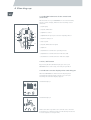
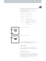
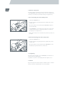
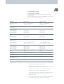
Adventure A10
Gebrauchsanweisung
D
Adventure A10
Operating Instructions
GB/US
Adventure A10
Instructions d‘utilisation
F
Adventure A10
Istruzioni per l‘uso
I
Neu!
New!
Noveau!
Nuovo!
3
Auflage
Edition
Edition
Edizione
Contents
2
Overview of the most important elements
Important safety instructions - must be observed
Dimensions of adventure
4
5
6
1
Standard delivery schedule
1.1
1.2
1.3
Optional parts
8
Technical data
9
General information regarding the batteries used 11
2
Individual functions on the adventure
2.1
2.2
2.3
2.4
2.5
2.6
2.7
2.8
2.9
2.10
2.11
2.12
2.13
2.14
2.15
2.16
2.17
Removing batteries
Installing batteries
Removing powered wheels
Fitting powered wheels
Removing steering wheels
Fitting steering wheels
Removing leg supports
Fitting leg supports
Folding up leg supports
Connecting or disconnecting the control unit
Battery charging
Replacing the bulb in the front light
Replacing the bulb in the indicator light
Replacing the bulb in the rear light
Replacing the fuse in the battery
Replacing the fuse in the chassis
Instructions regarding the interface on
the chassis
Folding the seat down or removing it completely
(function and standard seats
Fitting the seat unit
(function and standard seats)
2.18
2.19
12
13
14
15
17
17
18
19
20
20
21
22
22
23
24
24
25
26
27
2.20
Swivelling or removing the armrest
2.20.1 - on the function seat
2.20.2 - on the standard seat
28
28
2.21
2.21.1
2.21.2
29
30
Fitting the armrest
- on the function seat
- on the standard seat
2.22
Removing the backrest
2.22.1 - on the function seat
2.22.2 - on the standard seat
30
31
2.23
Fitting the backrest
2.23.1 - on the function seat
2.23.2 - on the standard seat
32
32
2.24
2.25
2.26
2.27
2.28
2.29
2.30
Folding down the backrest (only for function seat)
Removing the backrest cushion (only for function
seat) comfort and standard cushions
Fitting the backrest cushion (only for function
seat) comfort and standard cushions
Removing the seat cushion (only for function
seat) comfort and standard cushions
Fitting the seat cushion (only for function seat)
comfort and standard cushions
Removing the control unit
Fitting the control unit
33
33
34
35
35
36
37
3
3
Driving
3.1
3.2
3.3
3.3.1
3.3.2
3.4
Electrical / manual operation
Pelvic strap
Getting in and out
Function seat
Standard seat
Footrest information
4
Starting up
4.1
4.2
4.3
4.4
4.5
4.6
4.6.1
4.6.2
4.7
4.8
4.9
4.9.1
4.9.2
4.10
4.11
4.12
Individual elements of the control unit (overview)
On / Off button
Indicators on the display when switching on
Menu setting
Speed pre-selection
Drive away lock
Activating the drive away lock
Deactivating the drive away lock
Lighting
Horn
Modes of operation
Factory settings
Selection of the desired driving mode
Direction indicators and hazard warning lights
Fault indications on the display
Joystick steering
5
Instructions for driving
5.1
5.2
5.3
5.4
5.5
5.6
5.7
5.7.1
5.7.2
5.7.3
Driver safety
First driving tests
Instructions for driving the adventure
Dangerous ground
Range
Intended use
Storage, transport, shipping
Storage
Transport
Shipping
6
Care and maintenance
6.1
6.2
Cleaning
Maintenance
38
39
40
40
41
41
42
42
42
43
43
44
44
44
44
44
45
45
46
47
47
56
60
60
60
62
63
64
65
65
65
65
66
66
7
Service life guarantee and liability
7.1
7.2
Service life guarantee
Liability
67
67
8
Index
68
Overview of the most important components
4
Please open out the overview
diagram in the appendix
1
2
3
4
5
6
7
8
9
10
11
12
13
14
15
16
17
18
19
20
21
22
23
24
25
26
27
28
29
30
31
32
33
34
35
36
37
Battery unlocking device
Battery
Cap
Contact housing
Battery holding rod
Support bracket
Tilt support
Ejector
Powered wheel
Powered wheel receiver
Wheel marking
Wheel receiver marking
Steering wheel lock
Steering wheel
Steering wheel holder
Leg support lock
Leg support
Leg support holder
Leg support guideway
Control unit connection socket
Control unit connection plug
Charging socket cover
Charger plug
Charging socket
Battery fuse
Fuse compartment protective cover
Interface protective cover
Seat securing rod
Seating unit holder
Chassis holder stay
Armrest lock
Armrest
Armrest receiver function seat
Armrest star grip
Armrest receiver standard seat
Backrest lock
Backrest stay
38
39
40
41
42
43
44
45
46
47
48
49
50
51
52
53
54
55
56
57
58
59
60
61
62
63
64
65
66
67
68
69
70
71
72
73
Backrest
Backrest star grip
Backrest locator
Backrest rollers
Guide rail
Backrest guide
Backrest cushion Velcro fastener
Backrest cushion
Backrest form
Seat cushion Velcro fastener
Seat cushion
Seat form
Control unit holder
Cable clips
Control unit locking device
Control unit
Control unit receiver
Control unit studs
Lever (brake activation)
Control unit display
On / Off button for adventure
Menu control
Speed pre-selection adjusting wheel
Drive away lock
Joystick
On / Off switch for lights
Horn
Operating modes button
Direction of movement button left
Direction of movement button right
State of charge display
Operating mode display
Magnetic key
Lap belt
Lap belt bracket
Footrest
5
Important safety instructions must be observed!
For safety reasons, the adventure may only be operated by
persons who:
– have been instructed in its proper handling
– are physically and mentally in a state to control the
adventure with complete safety under all operating conditions.
The training for operating the device is included in the
scope of delivery and takes place by appointment with your
specialist dealer or one of the alber district managers. There
is no additional charge made for this service.
If you do not feel confident in handling the device, then in
Germany please contact our Service Center (telephone 08009096-250) or your specialist dealer.
Please also observe closely the maximum climbing
performance quoted by us. Under no circumstances must
this be exceeded.
The driving properties of the adventure may be affected by
electromagnetic fields that are produced by mobile phones
and other radiation equipment. The adventure itself can also
cause interference to electromagnetic fields.
!
If a mobile phone or similar device is to be used, the
adventure should provisionally be switched off on safe
ground. Also travel close to strong electric interference
fields should be avoided.
Intended use
The intended use of adventure is to provide indoor and outdoor mobility to persons restricted to a sitting position who
are capable of operating a powered wheelchair.
Disposal
This device, its battery pack and accessories are long-lasting
products.
However, they may contain materials that prove to be hazardous for the environment if they are disposed of in places
(e.g. landfills) that are not intended for this purpose according to the current applicable legislation in the respective
country.
The symbol of the “crossed-out refuse bin“ (in accordance
with WEEE Directive 2002/96/EC) is placed on this product to
remind you of your obligation to recycle.
Therefore, please act in an environmentally-conscious manner and bring this product to your regional recycling centre
at the end of its service life.
Please familiarise yourself with the applicable legislation in
your country regarding disposal, because the WEEE Directive does not apply in all European States. For example, this
product does not fall under the national implementation
of WEEE in the Electrical and Electronic Equipment Act as
means of transport.
These components are also alternatively taken back by alber
or alber dealers for proper, environmentally sound disposal.
Dimensions of adventure
6
Overall width, ready for driving
68 cm
Overall length and height, ready for driving
1) Dependent on the leg support angle set
2) Dependent on the backrest height set
98 cm(2)
111 cm(1)
Chassis dimensions (without seating unit)
1) Upper edge of seat attachment
44 cm(1)
93 cm (83,5 cm)*
Packing volume: seating unit (dismantled)
36 cm
29 cm
58-60 cm
* Measurements in brackets refer to adventure wheelchairs
with short wheelbase. As from January 2008, these
wheelchairs will be no longer available.
7
Packing volume: chassis (without wheels, with anti-tippers)
27
cm
93 cm (82,5 cm)*
62 cm (60 cm)*
45 cm
* Measurements in brackets refer to Adventure wheelchairs
with short wheelbase. As from January 2008, these
wheelchairs will be no longer available.
1 Standard delivery schedule
8
1.1 Optional parts
For details and availability of new accessories please see our
adventure homepage www.adventure-news.de
–
–
–
–
–
–
–
–
–
–
–
–
–
–
–
–
–
–
–
–
–
–
–
–
–
–
–
–
–
–
Adaptation for special backrests
Attendant control
Calf support
Crutch holder
Foam ball for joystick
Footbelt
Handrest extension
Headrest
Kerb climber
Lap belt
Lateral support
Light and indicators
Luggage bag
Luggage rack
Mechanical seat tilt
Middle control
Mudguards for the wheels
Off-board charger
Pelvic support
Protection bumper for control unit
Push handles
Rear-view mirror
Remote charger plug
Remote on/off switch
Seat height enhancement
Snow chains
Swivel arm for control unit
T-handle for joystick
Tie-down system for public transport
Tray table
As from January 2008, the following optional features of the
adventure wheelchairs will be no longer available:
- short wheelbase
- standard seat
- function seat with standard cushions.
Details and Information on these features contained in this
User Manual refer exclusively to older versions of adventure
wheelchairs that have already been in use.
9
1.2 Technical data
Version
6 km/h
Steering wheel size
75 / 70 – 6 (diameter 26 cm, width 7.5 cm)
Powered wheel size
90 / 70 – 10 (diameter 37 cm, width 10 cm)
Maximum speed
6 km/h
Braking system
Eddy current brake with energy recovery, electromagnetic elasticity
brake (locking brake)
Ground clearance
Turning circle
10 km/h**
10 km/h
12 km/h
Remarks
Max. pressure: 3,5 BAR
(50 PSI), recommended
pressure 2,5 BAR (36 PSI)
12 km/h
17 cm
88 cm (64 cm without footrests)
Climbing performance with 140 kg load
long wheelbase
18 %
18 %
18 %
short wheelbase
10 %
10 %
10 %
Motor design
Brushless direct current motors, integrated into the wheel hub
Drive design
2-step planetary transmission, maintenance free
Wheel torque
50 Nm
40 Nm
40 Nm
Motor nominal output
110 Watt
183 Watt
220 Watt
Motor peak output
475 Watt
620 Watt
750 Watt
Operating voltage
Max. wheel torque
24 Volt
Battery packs
Lead-gel, maintenance free, leak-proof,
24 Volt
Automatic
battery charger
6 amps charging current, with automatic switch-off and charge
conservation
Range (22 Ah)
with one battery pack
Approx. 20 km
Operation not
possible
Operation not
possible
Range (44 Ah)
with two battery packs
Approx. 45 km*
Approx. 45 km*
Approx. 45 km*
Max. additional load
Authorized for transportation by air freight by
DOT and IATA
140 kg
Total weight (empty with standard seat)
long wheelbase
96,7 kg
short wheelbase
96,4 kg
Max. obstacle height
long wheelbase
Without kerb climber maximum
of 8 cm, with kerb climber 12 cm
The kerb climber can be ordered
as an accessory
short wheelbase**
maximum 5 cm
Kerb climber cannot be fitted
**as from January 2008 no longer available
10
Weight of individual components
Version
6 km/h
10 km/h**
Battery pack
14,6 kg
Powered wheel
11,2 kg
Steering wheels with fork
2,3 kg
Chassis
26,2 kg
Seating unit
14,3 kg
Charger
1,1 kg
Total permitted weight
255 kg
12 km/h
Remarks
Dimensions
Total length ready to
drive (with anti-tippers)
111 cm
Total width ready to drive
68 cm
Power base (without seat)
long wheelbase
93 cm
short wheelbase
83,5 cm
Packing volume seating
unit (H x W x D)
36 cm x 50 cm x 60 cm
Packing volume chassis
(H x W x D)
Measured with tilt
supports and front
wheels outside
Dismantled, measured
with standard seat,
seat width 44 cm
Without front and rear
wheels, with anti-tippers
long wheelbase
27 cm x 62 cm x 93 cm
short wheelbase
30 cm x 60 cm x 82,5 cm
Operating temperature
Dependent on the leg
support angle set
Ambient temperature range (approx. –25 °C / +50 °C)
Manufacturer‘s guarantee 2 years on complete vehicle (except wearing parts), batteries 12 months
* The range varies depending on the terrain being travelled on and the prevailing driving
conditions. Under optimum driving conditions (even terrain, freshly charged batteries, ambient
temperature of 20 °C, even driving speed, etc.) the quoted ranges can be attained.
** Not available in the USA.
The adventure complies with the EU regulation for medical products 93/42/EWG, and 89/366/EWG
electromagnetic compatibility.
Changes in technology and design due to constant further development excepted.
Battery charger
For more details and technical information please refer to the instructions enclosed with the
charger.
11
1.3 General information regarding the batteries
used
The batteries in your adventure are maintenance free and
rechargeable. Their useful service life depends strongly on
the charging / discharging cycles. Through careful recharging
you increase the useful life of the batteries. The electronics
built into the adventure constantly monitor the state of
charge of the batteries and prevent complete discharging, if
properly observed.
– Avoid discharging the batteries completely. Recharge the
batteries of your adventure after every partial discharge,
i.e. after each use.
– Lead batteries are subject to self-discharge. Consequently,
the batteries of the adventure should, whenever possible,
always be connected to the alber mains charger. Due to
charging automation, which switches to charge conservation once the batteries are fully charged, it is impossible to
overcharge them.
– If lead batteries are stored over a longer period of time
(without being recharged), then they are subject to loss of
capacity. However, after several charge / discharge cycles
the full capacity is restored again.
– If improperly handled, batteries may lose electrolytic fluid.
This can cause injury to the skin and damage to clothing.
– If skin or eyes should come into contact with the electrolyte it is vital to rinse immediately with pure water and to
promptly consult a doctor.
– Never subject the battery to fire or try to burn it. This could
cause the battery to explode.
– Do not short-circuit the battery out. A short-circuit results
in very large currents which could damage the battery or
the adventure. At the end of its useful service life the battery may be returned to alber or an alber specialist dealer
for proper disposal.
The batteries in your adventure can be used and charged in
any position desired. They are classified as being as safe as
dry cells and are authorized for transportation by air freight
by DOT and IATA.
2 Individual functions on the adventure
12
Your adventure is a compactly constructed vehicle.
Individual and service functions may be carried out with
a few hand movements and largely without the use of any
tools.
Certain of the control elements shown in the following
diagrams may deviate from those of your adventure as they
are provided for left-handed or right-handed persons and so
some control elements are located on the opposite side.
58
2.1 Removing batteries
The following instructions apply for operation with one as
well as with two batteries.
– Switch the adventure off by pressing the On / Off button
[58] on the control unit (see chapter 4.2).
– Fold the seat forward (see chapter 2.18).
– Press the unlocking mechanism for the battery [1], located
at the side, downwards.
Õ
– Remove the battery [2].
1
Õ
2
13
2.2 Installing batteries
The following instructions apply for operation with one as
well as with two batteries.
– Fold the seat forward (see chapter 2.18).
– Fit the cap [3] to the contact housing [4].
Õ
4
– When operating with only one battery: Place the cap [3]
on the right contact housing [4].
– Place the battery in the middle of the adventure
3
– When operating with two batteries:
Place the cap [3] on the centre contact housing [4].
Õ
4
3
– Press the unlocking mechanism for the battery [1], located
at the side, downwards.
– Place one battery [2] on the left, the other battery [2] to the
right of the holding rod [5].
– Alternatively (operation with only one battery):
place the battery [2] in the middle of the holding rod [5].
– When properly positioned the batteries fall automatically
into the contact housings. If this is not the case, then shift
the batteries to the left or right on the holding rod [5].
1
– Pull the unlocking mechanism upwards [1].
– Switch the adventure on again by pressing the
On / Off button [58] on the control unit.
Õ
5
2
14
!
The cap prevents moisture entering the contact housing.
Never use your adventure without having placed the cap in
the correct position first.
2.3 Removing powered wheels
– Switch the adventure off by pressing the On / Off button
[58] on the control unit.
– Fold the support bracket [6] on both anti-tippers [7] downwards.
– Stand with one foot placed against the support bracket [6]
on the right-hand side (to prevent sliding).
7
6
– Take the wheel in both hands and pull the adventure
simultaneously back and upwards.
– The right-hand side of the chassis now rests on the support bracket [6], the wheel is free.
– Repeat the process on the left-hand side.
15
– With one hand pull the ejector [8] back and simultaneously
with the other hand lift the wheel up slightly by its rim. The
powered wheels [9] can now be pressed out of their receivers [10].
– Pull the wheels [9] completely off the receivers [10] and set
them aside.
8
Õ
10
Õ
9
!
Never lay the wheels down on their stub axles.
When removed from the vehicle, the wheels must never be
cleaned with water as moisture may get into the electronics
through the axle.
2.4 Fitting powered wheels
– Make sure that the brake lever is next to the chassis (see
chapter 3.1), otherwise the wheels cannot be fitted.
– If not already done, place the adventure up on both its support brackets [6] (see chapter 2.3).
12
11
16
– Adjust the marking on the wheel [11] to correspond to the
marking on the wheel receiver [12].
– Push the wheels [9[ fully into the wheel receivers [10].
– Fold the support brackets [6] back in.
– Make sure that the support brackets [6] are securely folded
away.
12
11
6
6
!
If the powered wheels [9] should not be completely engaged in the wheel receivers [10], you will get an optical
warning message on the display of the control unit. An
audible warning signal will also be issued.
!
Prior to fitting the wheels always check their stub axles and
the wheel receivers on the chassis for signs of dirt. Dirty
stub axles may cause jamming during the fitting process.
17
2.5 Removing steering wheels
– Position the wheels in the direction of travel.
– Lift the adventure up on the side where you wish to remove the wheel.
13
Õ
– With the other hand press the locking device [13] located
under the wheel fork.
– Keeping the lock [13] pressed, pull the steering wheel [14]
downwards out of its holder.
– Place the steering wheel [14] aside.
– Repeat the above steps on the other side.
Õ
14
!
Always ensure that the wheel stub axles are not damaged
during the removal process.
2.6 Fitting steering wheels
15
13
14
– Lift the adventure up on the side where you wish to fit the
wheel.
– Take the steering wheel [14] into the other hand, press
the locking device [13] and guide the wheel shaft into the
holder [15].
18
– Make sure, by turning the steering wheel [14] a number of
times, that it is securely located in the holder [15] and will
not fall out by itself.
– Repeat the above steps on the other side.
!
Prior to fitting the wheels always check their stub axles
and the wheel receivers on the chassis for signs of dirt.
Dirty stub axles may cause jamming during the fitting
process.
2.7 Removing leg support
Õ
– Press the locking device [16] upwards and simultaneously
swivel the leg support [17] upwards about 90 degrees.
– Pull the leg support [17] out of the holder [18].
16
18
17
19
2.8 Fitting leg supports
– Push the leg support guideway [19] into the holder [18]
– Fold the leg support [17] downwards; the locking device
engages automatically.
Õ
19
17
18
20
2.9 Folding up footrests
– The front part of the leg supports [73] can be folded up, if
required, as shown in the diagram.
73
2.10 Connecting or disconnecting the control
unit
Depending on the adventure model, the control unit
connection socket [20] is located either on the left-hand or
right-hand front side underneath the seat.
– Carefully insert the plug [21] from the control unit into the
connection socket [20] on the adventure.
– The connection to the control unit is established automatically.
20
21
21
– If you wish to disconnect the control unit from the
adventure, you just need to gently pull the control unit
plug [21] out of the connection socket [20].
20
21
!
The markings on the connection socket [20] and on the plug
[21] must be aligned.
2.11 Battery charging
Depending on the adventure model, the charging socket
is located either on the left-hand or right-hand front side
underneath the seat.
– Push the cover [22] over the charging socket to the side.
– Insert the plug [23] of the charger gently into the charging
socket [24].
– Connect the charger to a mains power supply.
22
23
!
24
For more details and technical information please refer to
the instructions enclosed with the charger.
22
2.12 Replacing the bulb in the front light
– Switch off the adventure at the control unit.
– Unscrew and remove the screw on the front of the housing.
– Replace the defective bulb by a new one.
– Screw the two parts of the housing together again.
Õ
!
6 V / 24 W
K16439F1
Make sure that no wires are jammed when the housing is
assembled again.
2.13 Replacing the bulb in the direction
indicator light
– Switch off the adventure at the control unit.
– Unscrew and remove the two screws on the upper and
lower sides of the housing.
– Replace the defective bulb by a new one.
– Screw the housing back onto the holder.
23
Õ
12 V / 18 W
K15608-n9J
!
Make sure that no wires are jammed when the housing is
assembled again.
2.14 Replacing the bulb in the rear light
– Switch off the adventure at the control unit.
– Pull the two halves of the housing apart.
– Replace the defective bulb by a new one.
– Replace the red plastic housing back on the plastic holder.
12 V / 5 W
E1 2FW
!
Make sure that no wires are jammed when the housing is
assembled again.
24
2.15 Replacing the fuse in the battery
– Push the fuse [25], which is located at the front of the battery housing, out of the housing.
– Take a fuse [25] of the same type and insert it in place.
25
25
!
Never open the battery housing.
Should the fuse need replacing several times at short
intervals, then please contact the alber Service Center.
2.16 Replacing the fuse in the chassis
– If not already done, remove both batteries from the chassis
(see chapter 2.1).
– Open the protective cover [26] on the back of the chassis
with the aid of a screwdriver.
– Remove the defective fuse.
– Insert a new fuse of the same type.
26
25
– Close the protective cover [26] and tighten the screw.
20A 3A 1A 7,5A
– Replace the batteries on the chassis (see the chapter
„Replacing batteries“).
F3 F4 F5 F6
40A
F2
40A
F1
!
Always remove both batteries prior to changing the fuse.
Should the fuse need replacing several times at short
intervals, then please contact the alber Service Center.
2.17 Instructions regarding the interface on the
chassis
27
!
There is an interface located on the chassis of the adventure
which can be used by your specialist dealer for medical
accessories to attach various additional features, such as
electrical seat adjustment, for example.
The protective cap [27] on the interface must not be
removed, as damage may occur to the contacts located
underneath it.
26
2.18 Folding the seat down or removing it
completely (function and standard seats)
– Press the securing rod [28] on the frame, located above the
batteries, upwards.
– Fold the entire seating unit forwards.
– If desired, the complete seating unit may now also be
removed.
28
!
If the seating unit is to be removed completely, then the
control unit connection plug [21] must be disconnected
first (see also chapter 2.10).
27
2.19 Fitting the seating unit
(function and standard seats)
– Hold the seating unit above the chassis at an angle of
about 45 degrees.
– Push the holder [29] on the seating unit into the chassis
holder stay [30] on the chassis.
– Fold the entire seating unit downwards. This will cause it
to automatically engage with the chassis.
29
30
– Check that it is locked in place. It must not be possible to
remove the seating unit from the chassis without it being
unlocked first (see chapter 2.18).
– Reconnect the control unit (see chapter 2.10).
29
30
28
2.20 Swivelling or removing the armrest
2.20.1 Function seat
32
33
– Pull on the locking device [31] at the lower end of the
armrest.
– Simultaneously tip the armrest [32] backwards.
– The armrest can now stay (folded away) on the adventure,
or it can be removed entirely.
31
!
– If the armrest is folded back into its initial position, it
engages automatically in the receiver [33].
If the armrest [32] with the control unit is to be removed,
then you must first disconnect the control unit connection
plug [21] (see chapter 2.10).
2.20.2 Standard seat
– The armrest on the standard seat cannot be swivelled but
only removed.
– Loosen the star grip [34] on the armrest [32].
– Pull the armrest [32] out of the receiver [35] and place it
aside.
34
29
35
32
!
If the armrest [32] with the control unit is to be removed,
then you must first disconnect the control unit connection
plug [21] (see chapter 2.10).
2.21 Fitting the armrest
2.21.1 Function seat
32
33
– Push the armrest [32] into its receiver [33].
– Tip the inserted armrest [32] forwards until it engages in
the receiver [33].
32
– If required, reconnect the control unit (see chapter 2.10).
33
30
2.21.2 Standard seat
– Push the armrest [32] into its receiver [35].
– Tighten the star grip [34] firmly.
– If required, reconnect the control unit (see chapter 2.10).
35
32
34
2.22 Removing the backrest
2.22.1 Function seat
– Press the backrest locking lever [36] down with the one
hand.
– Simultaneously with the other hand pull the entire backrest
upwards by the stay [37].
37
– Place the backrest [38] aside.
36
31
38
!
Always make sure that the guide rollers are not dirty or
damaged.
2.22.2 Standard seat
– Loosen and remove the four star grips [39].
– Pull the entire backrest [38] up by the stay [37].
– Place the backrest [38] aside.
40
39
39
– For safe keeping, screw the star grips [39] into the locator
[40].
37
!
In removing the backrest, observe the position of the holes
into which the star grips are screwed.
When the backrest is re-fitted, the star grips should be
screwed into exactly the same holes as otherwise the position of the backrest will be different.
32
2.23 Fitting the backrest
2.23.1 Function seat
– Push the backrest rollers [41] into the guide rails [42].
– Allow the backrest [38] to slide completely into the guide
rails [42].
– The backrest [38] engages automatically when it reaches
its end position.
38
41
42
2.23.2 Standard seat
– Push the backrest [38] into the locator [40].
– Screw the backrest [38] to the locator [40] with the star
grips [39].
38
40
39
!
39
Screw the backrest back into the same position (watch for
the holes) in which it was prior to being removed.
33
2.24 Folding down the backrest
(only for function seat)
38
– Press the backrest locking lever [36] downwards with the
one hand.
37
– Simultaneously with the other hand pull the entire backrest upwards by the stay [37] until the guide [43] extends
beyond the guide rail [42].
– Fold the backrest [38] over.
43
42
36
– In order to return the backrest [38] to its initial position
push it back into the guide rail [42].
It will engage automatically.
2.25 Removing the backrest cushion
(only for function seat)
45
34
– Undo the Velcro fastener [44] situated at the top edge of
the backrest cushion.
– Pull the backrest cushion [45] off.
44
45
2.26 Fitting the backrest cushion
(only for function seat)
45
46
– Place the backrest cushion [45] properly oriented onto the
backrest form [46].
– Press the backrest cushion [45] against the backrest form
[46], where it will be held by the Velcro fasteners.
– Pull the Velcro fastener [44] situated at the top edge of the
backrest cushion over the top edge of the backrest form.
44
– Press the Velcro fastener [44] against the backrest form.
35
2.27 Removing the seat cushion
(only for the function seat)
– Undo the Velcro fastener [47] situated at the front lower
edge of the seat cushion.
– Pull the seat cushion [48] off.
47
48
2.28 Fitting the seat cushion
(only for the function seat)
– Place the seat cushion [48] properly oriented onto the seat
form [49].
– Press the seat cushion [48] against the seat form [49],
where it will be held by the Velcro fasteners.
48
49
– Pull the Velcro fastener [47] situated at the front edge of
the seat cushion over the front edge of the seat form.
– Press the Velcro fastener [47] against the lower side of the
seat form.
47
36
2.29 Removing the control unit
– If not already done, first pull the control unit plug out of the
connection socket on the chassis (see chapter 2.10).
– Undo and remove the two clips [51] situated at the sides of
the holder [50].
The cable to the control unit that is inside the holder [50] is
now exposed.
50
– Pull the locking device [52] underneath the control unit [53]
backwards.
51
51
– Take the control unit [53] out of the receiver [54] and place
it aside.
53
52
54
37
2.30 Fitting the control unit
– Pull the locking device [52] backwards.
– Place the studs [55] on the control unit into the receiver
[54] on the cantilever.
– Push the locking device [52] forwards.
The control unit [53] should now be firmly attached to the
holder [50].
55
55
54
– Place the control unit cable into the groove underneath the
holder [50].
52
– Push the clips [51] into their locations in the holder [50].
– Connect the control unit to the chassis (see chapter 2.10).
53
52
51
50
3 Driving
38
3.1 Electrical / manual operation
The lever [56] for mechanical activation / deactivation of the
electromechanical brake is situated (depending on the model
of adventure) on the left-hand or right-hand front side of the
chassis.
When the electrical drive is switched off the adventure can
be switched into manual operation by deactivating the brake.
Electrical operation
– If the lever [56] is up next to the chassis then electrical
operation is activated on the adventure.
The two powered wheels can be addressed via the control
unit.
56
!
During activated electrical operation the adventure may
be parked on gradients (up or down) with a maximum
inclination of 18 %.
The powered wheels are self-locking so that it is not
necessary to apply an additional brake.
Manual operation
– To activate manual operation switch the adventure off and
push the lever [56] away from the chassis.
– In this setting the brakes are deactivated to allow an
escorting person to push the vehicle.
56
56
!
In manual operation the adventure may only be parked on
the level as the electromechanical brake is deactivated. In
an emergency, the lever [56] can be pressed forwards with
light pressure so that the brake is applied and the
adventure immediately comes to a standstill.
!
When electrical operation is switched on and the brake
is deactivated (lever [56] pulled back) a warning signal is
sounded. The brake symbol also flashes on the control
unit display. In this setting the adventure is braked by the
electrical drive and no movement is possible.
39
3.2 Lap belt (optional extra)
A lap belt [71] may be ordered from alber as an optional
extra. It can be fitted subsequently to your adventure by your
specialist dealer.
71
72
Function seat
The lap belt bracket [72] is permanently attached to the
function seat.
72
Standard seat
The lap belt bracket [72] is screwed to the backrest with star
grips [39].
If the backrest is removed (chapter 2.22.2) and then reattached (chapter 2.23.2), the lap belt bracket [72] must be
taken off and re-attached again too.
39
72
40
3.3 Getting in and out
3.3.1 Function seat
Getting into the adventure
– Position the adventure as close as possible to your seat
(if required, ask someone else to help you).
– Make sure that the adventure is switched off.
– Make sure that the adventure is in electrical operating
mode (see chapter 3.1).
31
– Pull out the armrest lock [31] at the lower end of the armrest.
– At the same time, fold the armrest [32] back (the armrest
may be left folded back on the adventure or it may be
removed entirely).
– Slide onto your adventure.
– Fold the armrest [32] back to its original position (it will
click into position automatically).
!
If the armrest [32] holding the control unit is to be removed
entirely, then you must first pull out the control unit plug
[21] (see chapter 2.10).
If you do not possess sufficient muscular strength to get in,
then you should ask an escorting person for help. If possible
use a board to slide across.
Getting out of the adventure
– Position the adventure as close as possible to your seat.
– Switch the adventure off.
– Switch the adventure into electrical operating mode (see
chapter 3.1).
– Pull out the armrest lock [31] at the lower end of the armrest.
– At the same time, fold the armrest [32] back (the armrest
may be left folded back on the adventure or it may be
removed entirely).
41
– Get out of the adventure.
– Fold the armrest [32] back to its original position (it will
click into position automatically).
!
If the armrest [32] holding the control unit is to be removed
entirely, then you must first pull out the control unit plug
[21] (see chapter 2.10).
If you do not possess sufficient muscular strength to get
out, then you should ask an escorting person for help. If
possible use a board to slide across.
3.3.2 Standard seat
Getting in and out of your adventure is basically the same
as described in chapter 3.3.1 above. On the standard seat,
however, the armrest cannot be folded back, it must be
removed entirely.
For details please read chapters 2.20.2 and 2.21.2.
3.4 Footrest information
When the adventure is pushed without occupant, the footrests must be folded up to make sure that mud guards and
wheels do not scrape on them.
4 Starting up
42
4.1 Individual elements of the control unit
(overview)
All the functions of your adventure are executed centrally
via the control unit [53], which has the following control
elements:
57
– [57] Display
– [58] On / Off button
63
58
– [59] Menu control
64
59
– [60] Maximum speed pre-selection adjusting wheel
65
60
61
– [61] Drive away lock
– [62] Joystick
62
– [63] On / Off button for lights
– [64] Horn
66 67 53
– [65] Button to activate the operating modes
– [66] Button to activate direction indicator (left)
– [67] Button to activate direction indicator (right)
4.2 On / Off button
By pressing the On / Off button [58] you cause your
adventure to become ready / not ready for operation.
4.3 Indicators on the display when switching on
When the adventure is switched on the display [57] is
automatically activated and, in quick succession, the
following two standard displays appear:
Standard display 1
Standard display 2
At the same time a system scan is carried out to check for
potential errors, which if found, are indicated by visual and
acoustic signals (see chapter 4.11).
43
If your adventure is ready for operation, the display switches
over to operating display mode. Here the state of charge
[68] of the battery and the selected operating mode (Indoor /
Outdoor) [69] are always shown.
The bar in the battery charge symbol [68] indicates the
following states of charge:
– 5 black bars:
Battery capacity > 95 %
– 4 black bars:
Battery capacity > 80 %
– 3 black bars:
Battery capacity > 60 %
– 2 black bars:
Battery capacity > 40 %
– 1 black bar:
Battery capacity > 20 %
(Recharging is essential immediately)
– No black bar:
The adventure will be switched off
shortly as there is no power available
any more.
Error code 2 is displayed.
Operating mode Indoor display
68
69
Operating mode Outdoor display
68
The background illumination on the display goes out
30 seconds after the adventure is switched on, however, the
current operating status continues to be shown.
4.4 Menu setting
The menu control button is used to control and activate
electrical seat adjustments, which may be attached. If no
electrical seat adjustment motors are attached, then the button has no function.
4.5 Speed pre-selection
With the infinitely variable adjusting wheel [60] you can
pre-select any desired maximum speed that your adventure
should attain when the joystick is at its fullest displacement.
For your first trips with the adventure we recommend that
you select low maximum speed settings to enable you to
learn how the system works.
44
4.6 Drive away lock
The drive away lock [61] prevents the unintentional start up
of the adventure and avoids it being used in an unauthorized
manner; it is activated / deactivated using a magnetic key.
4.6.1 Activating the drive away lock
– Switch the adventure on.
– Hold the magnetic key [70] against the symbol [61] on the
control unit.
70
– The drive away lock is activated, the adventure switches
off automatically.
– If the adventure is now switched on again the control unit
is without any function, a warning indicator is shown on
the display (see chapter 4.11).
61
– When drive away lock is activated only manual operation is
possible.
4.6.2 Deactivating the drive away lock
– Switch the adventure on.
– Hold the magnetic key [70] against the symbol [61] on the
control unit.
70
– The drive away lock is deactivated, the adventure can immediately be operated via the control unit.
61
4.7 Lighting
The front and rear lights of your adventure are switched on
and off using the button [63].
A symbol is shown on the display when the lights are on.
4.8 Horn
By pressing the horn button [64] an audible signal is emitted
which continues until the button is released again.
45
4.9 Operating modes
4.9.1 Factory settings
Your adventure can operate in two modes - Indoor and
Outdoor mode.
There are different operating states behind these two modes
which can be distinguished as follows:
Function
Indoor mode
Outdoor mode
Maximum speed
forwards
60 % of the maximum
attainable speed
100 % of the maximum
attainable speed
Maximum speed
backwards
3,0 km/h
3,0 km/h
Acceleration time
Version 6 km/h
Version 10 km/h*
Version 12 km/h
2,3 seconds
5,7 seconds
6,3 seconds
1,8 seconds
4,6 seconds
5,1 seconds
Slow down time
Version 6 km/h
Version 10 km/h*
Version 12 km/h
2,8 seconds
6,9 seconds
7,6 seconds
2,3 seconds
5,7 seconds
6,3 seconds
Turning speed
Version 6 km/h
Version 10 km/h*
Version 12 km/h
31 % of maximum speed
20 % of maximum speed
16 % of maximum speed
28 % of maximum speed
28 % of maximum speed
15 % of maximum speed
Turning acceleration / slow down
Version 6 km/h
0,04 seconds
Version 10 km/h*
0,03 seconds
Version 12 km/h
0,03 seconds
0,08 seconds
0,08 seconds
0,06 seconds
Horn
Active
Active
Braking onset
Time delayed by 30 seconds
Time delayed by 30 seconds
Self switch off time
1 hour
1 hour
Driving signal
displacement joystick
100 %
100 %
Change of direction joystick
No change
No change
* Not available in the USA.
Please note the following interpretations:
– Maximum speed forwards: the maximum attainable speed
when the joystick is at full displacement.
– Maximum speed backwards: the maximum attainable
speed when the joystick is at full displacement
– Acceleration time: the time taken to accelerate from standstill or from the speed being travelled at to the pre-set
maximum speed.
– Slow down time: the time taken for braking from the maximum speed to the desired speed or to a standstill.
46
– Turning speed: the maximum speed at which an arc of a
circle or curve is travelled at.
– Turning acceleration / slow down: the time taken for acceleration or slowing down while moving round a bend.
– Horn: activation or deactivation of the audible signal.
– Braking onset: the time between the last issuance of a driving command until the electromagnetic brakes are applied.
– Self switch off time: the time during which the adventure
remains ready for use before it switches itself off (to save
energy).
– Driving signal displacement joystick: the maximum joystick displacement required in order to give a driving command.
– Change of direction joystick: changing the direction of
movement stored in the joystick.
!
All the above driving parameters can be adjusted to your
individual requirements. Please contact your specialist
dealer for this. He will be happy to advise you and to
program the desired settings for you.
57
4.9.2 Selection of the desired driving mode
Indoor or Outdoor mode is activated by pressing the button
[65]. A visual control indicator is shown on the display [57].
65
Display shows:
Indoor mode activated („House“ visible)
Outdoor mode activated („House“ not visible)
47
4.10 Direction indicators and hazard warning
lights
By pressing the button [66] you turn on the left direction
indicator, by pressing the button [67] you turn on the one
to the right. Pressing the respective button again turns the
indicator off.
If both buttons ([66] and [67]) are pressed simultaneously,
you will turn on the hazard warning lights. To turn them off,
simply press one of the two buttons [66] or [67].
Activating them results in a corresponding indication on the
display.
4.11 Fault indications on the display
Prior to driving your adventure you should carry out a
functional check on it.
Check that all components are properly tight, that the
steering wheels move freely and test the brakes on level
ground. The batteries should also be fully charged.
Faults that may occur on your adventure are indicated on
the display of the control unit. The following indications are
possible:
Display indication
(letters flash)
Control unit symbol flashes
Fault description
What to do
Hardware fault on
control unit
Contact your specialist
dealer or the
alber Service Center
EEPROM faulty or
wrongly coded
Contact your specialist
dealer or the
alber Service Center
Batterie voltage range
error
1. Battery defective.
Check where 2
batteries are involved
by inserting separately
in central position.
Check/replace defective
fuse on battery or
replace complete
battery.
2. Battery fully charged.
Overvoltage error when
driving uphill. Remedy
approx. 0,5 km uphill!
3. Battery flat! Charge
storage batteries
Exclamation mark lit up
Code 0
Control unit symbol flashes
Exclamation mark flashes
Code 1
Control unit symbol flashes
Exclamation mark lit up
Code 2
48
Drive symbol flashes
Uneven drive
coding
Fit power-assisted
wheels with identical
speed values on both
sides
No communication with
„left“ drive
Switch wheels.
Contact your specialist
dealer or the alber
Service Center if the
error code continues to
be displayed
No communication with
„right” drive
Switch wheels.
Contact your specialist
dealer or the alber
Service Center if the
error code continues to
be displayed
No communication with
interface
Contact your specialist
dealer or the
alber Service Center
No communication with
peripheral module
Contact your specialist
dealer or the alber
Service Center
Joystick fault on
control unit
Contact your specialist
dealer or the
alber Service Center
Exclamation mark lit up
Code 3
Drive symbol flashes
Exclamation mark lit up
Letter »L« flashes
Code L4
Drive symbol flashes
Exclamation mark lit up
Letter »R« flashes
Code R4
Interface symbol flashes
Exclamation mark lit up
Letter »S« flashes
Code S4
Interface symbol flashes
Exclamation mark
symbol flashes
Letter »P« flashes
Code P4
Control unit symbol flashes
Exclamation mark lit up
Code 5
49
Battery symbol flashes
Exclamation mark flashes
Code 6
Battery configuration
error and/or
detection faulty
(L6 = left battery pack
R6 = right battery pack)
Contact your specialist
supplier or the
alber Service Center
if the error conde
continues to be
displayed
Control unit symbol flashes
No communication
with special control
Driving with control unit
possible after reactivation on control
panel!
Contact your specialist
dealer or the alber
Service Center if the
error code continues to
be displayed
Drive unit not
compatible with
control unit
Fit power-assisted
wheels permitted
for top speed limit
CPU fault on
control unit
Contact your specialist
dealer or the alber
Service Center
RAM error on
control unit
Contact your specialist
dealer or the alber
Service Center
ROM horizontal parity
error on control unit
Contact your specialist
dealer or the alber
Service Center
Interface symbol flashes
Exclamation mark lit up
Code 7
Control unit symbol flashes
Drive symbol flashes
1. Driving with 1 battery
pack: battery not inserted in central position!
2. Driving with 2
battery packs:
- one battery set
defective
- battery fuse (40A)
defective
- battery detection in
interface defective
Rapid error diagnosis
by inserting the
batteries consecutively
in the middle position!
Exclamation mark lit up
Code 8
Control unit
symbol flashes
Exclamation mark
symbol lit up
Code 9
Control unit
symbol flashes
Exclamation mark
symbol lit up
Code 10
Control unit
symbol flashes
Exclamation mark
symbol lit up
Code 11
50
Drive symbol flashes
„Left“ drive hardware/
system error
Contact your specialist
dealer or the
alber Service Center
„Right“ drive hardware/
system error
Contact your specialist
dealer or the
alber Service Center
„Left“ drive overload
switch-off
Brief overloading deactivates temperature!
System is operationally
ready again after
deactivation and
reactivation
„Right“ drive overload
switch-off
Brief overloading deactivates temperature!
System is operationally
ready again after
deactivation and
reactivation
„Left“ drive battery
voltage range error
Switch wheels.
Contact your specialist
dealer or the
alber Service Center
if the error code
continues to be
displayed
„Right“ drive battery
voltage range error
Switch wheels.
Contact your specialist
dealer or the
alber Service Center
if the error code
continues to be
displayed
Exclamation mark lit up
Letter »L« flashes
Code L0
Drive symbol flashes
Exclamation mark lit up
Letter »R« flashes
Code R0
Drive symbol flashes
Temperature symbol lit up
Exclamation mark lit up
Letter »L« flashes
Code L1
Drive symbol flashes
Temperature symbol lit up
Exclamation mark lit up
Letter »R« flashes
Code R1
Drive symbol flashes
Exclamation mark lit up
Letter »L« flashes
Code L2
Drive symbol flashes
Exclamation mark lit up
Letter »R« flashes
Code R2
51
Drive symbol flashes
„Left“ drive operating
temperature switch-off
Drive overheating deactivates temperature!
Allow system to cool!
(Cooling period
depends on ambient
temperature!)
„Right“ drive operating
temperature switch-off
Drive overheating deactivates temperature!
Allow system to cool!
(Cooling period
depends on ambient
temperature!)
Temperature symbol lit up
Exclamation mark lit up
Letter »L« flashes
Code L3
Drive symbol flashes
Temperature symbol lit up
Exclamation mark lit up
Letter »R« flashes
Code R3
Temperature symbol flashes „Left“ drive operating
temperature warning
Exclamation mark flashes
Battery capacity
display lit up
Drive overheating
warning!
Reduce load, otherwise
temp. system shutdown
with error L3/R3!
Code L
Temperature symbol flashes „Right“ drive operating
temperature warning
Exclamation mark flashes
Battery capacity
display lit up
Drive overheating
warning!
Reduce load, otherwise
temp. system shutdown
with error L3/R3!
Code R
Drive symbol flashes
Wheel code/“Left“
electronic drive error
Contact your specialist
dealer or the alber
Service Center
Wheel code/“Right“
electronic drive error
Contact your specialist
dealer or the alber
Service Center
Exclamation mark
symbol lit up
Letter »L« flashes
Code L5
Drive symbol flashes
Exclamation mark
symbol lit up
Letter »R« flashes
Code R5
52
Interface symbol flashes
Hardware fault
at the interface
Contact your specialist
dealer or the
alber Service Center
CPU fault on interface
Contact your specialist
dealer or the alber
Service Center
RAM error on interface
Contact your specialist
dealer or the alber
Service Center
ROM horizontal parity
error on interface
Contact your specialist
dealer or the alber
Service Center
»Left« indicator
light defective
Defective indicator
light (change bulb)
Exclamation mark lit up
Letter »S« flashes
Code S0
Interface symbol flashes
Exclamation mark
symbol lit up
Letter »S« flashes
Code S1
Interface symbol flashes
Exclamation mark
symbol lit up
Letter »S« flashes
Code S2
Interface symbol flashes
Exclamation mark
symbol lit up
Letter »S« flashes
Code S3
Interface symbol flashes
Exclamation mark
symbol flashes
Contact your specialist
dealer or the alber
Service Center if the
fault cannot be
remedied in this manner
Letter »S« flashes
Code S5
Interface symbol flashes
Exclamation mark
symbol flashes
Letter »S« flashes
Code S6
»Right« indicator
light defective
Defective indicator
light (change bulb)
Contact your specialist
dealer or the alber
Service Center if the
fault cannot be
remedied in this manner
53
Complete seat unit*
flashes
Interface symbol flashes
Hardware fault on
peripheral module
(different drive and/or
relay actuation)
Contact your specialist
dealer or the alber
Service Center
CPU fault on peripheral
module
Contact your specialist
dealer or the alber
Service Center
RAM error on peripheral
module
Contact your specialist
dealer or the alber
Service Center
ROM horizontal parity
error on peripheral
module
Contact your specialist
dealer or the alber
Service Center
Exclamation mark
symbol lit up
Letter »P« flashes
Code P0
Complete seat unit*
flashes
Interface symbol
flashes
Exclamation mark
symbol illuminates
Code P1
Complete seat unit*
flashes
Interface symbol
flashes
Exclamation mark
symbol lit up
Code P2
Complete seat unit*
flashes
Interface symbol
flashes
Exclamation mark
symbol lit up
Code P3
Complete seat unit*
flashes
Interface symbol
flashes
Erroneous potentiometer Contact your specialist
position feedback signal dealer or the alber
(only applies to drives
Service Center
with feedback signal)
Exclamation mark
symbol lit up
Letter »P« flashes
Code P5
Complete seat unit*
flashes
Interface symbol
flashes
Exclamation mark
symbol flashes
Letter »P« flashes
Code P6
Multiple occupancy
of »left« and/or »right«
indicator key function
Contact your specialist
dealer or the alber
Service Center
54
Complete seat unit*
flashes
Interface symbol
flashes
Multiple occupancy of
»decelerate« and/or
»accelerate« indicator
key function
Contact your specialist
dealer or the alber
Service Center
No counter-function
to »left« and/or »right«
indicator key
function exists
Contact your specialist
dealer or the alber
Service Center
No counter-function to
»decelerate« and/or
»accelerate« indicator
key function exists
Contact your specialist
dealer or the alber
Service Center
Hardware fault on
special control
Contact your specialist
dealer or the alber
Service Center
CPU fault on special
control
Contact your specialist
dealer or the alber
Service Center
RAM error on
special control
Contact your specialist
dealer or the alber
Service Center
Exclamation mark
symbol flashes
Letter »P« flashes
Code P7
Complete seat unit*
flashes
Interface symbol flashes
Exclamation mark symbol
flashes
Letter »P« flashes
Code P8
Complete seat unit*
flashes
Interface symbol
flashes
Exclamation mark
symbol flashes
Letter »P« flashes
Code P9
Control unit
symbol flashes
Interface symbol
flashes
Exclamation mark
symbol lit up
Letter »E« flashes
Code E0
Control unit
symbol flashes
Interface symbol
flashes
Exclamation mark
symbol lit up
Letter »E« flashes
Code E1
Control unit
symbol flashes
Interface symbol
flashes
Exclamation mark
symbol lit up
Letter »E« flashes
Code E2
55
Control unit
symbol flashes
ROM horizontal parity
error on special control
Contact your specialist
dealer or the alber
Service Center
Joystick fault on
special control
Contact your specialist
dealer or the alber
Service Center
Internally-defined error
on special control
Contact your specialist
dealer or the alber
Service Center
Internally-defined
warning 1 on special
control
Contact your specialist
dealer or the alber
Service Center
Internally-defined
warning 2 on
special control
Contact your specialist
dealer or the alber
Service Center
Special control
not functioning
Contact your specialist
dealer or the alber
Service Center
Interface symbol
flashes
Exclamation mark
symbol lit up
Letter »E« flashes
Code E3
Control unit
symbol flashes
Interface symbol
flashes
Exclamation mark
symbol lit up
Letter »E« flashes
Code E4
Control unit
symbol flashes
Interface symbol
flashes
Exclamation mark
symbol lit up
Letter »E« flashes
Code E5
Control unit
symbol flashes
Interface symbol
flashes
Exclamation mark
symbol flashes
Letter »E« flashes
Code E6
Control unit
symbol flashes
Interface symbol
flashes
Exclamation mark
symbol flashes
Letter »E« flashes
Code E7
Letter »E« flashes
Exclamation mark
symbol flashes
Code E
56
Brake symbol flashes
Battery capacity
dislay lit up
Left and right brake
manually vented
(L = left brake only,
R = right brake only)
Move braker lever to
driving position!
Additional L or R display
indicates actuating pin
jammed in wheel
ejector or drive
1. Remove wheels,
check actuating pin and
Bowden cable in wheel
ejector
2. Switch wheels from
left to right (indicates
which actuating pin
may be jammed in drive
Parking brake active
Deactivate with
magnetic key on control
unit key symbol!
Exclamation mark lit up
Entire wheelchair
symbol flashes
Exclamation mark lit up
!
The complete seat unit specified in the “Display indication“
column consists of the backrest, seat and leg support.
These 3 symbols should flash together in the event of Code
“P“ faults occurring.
4.12 Joystick steering
The function of the joystick on your adventure may best be
described as a fictitious combination of the steering wheel,
gear change and accelerator of a motor car. That means that
all control commands from the driver of the adventure are
transmitted to the two powered wheels via the joystick. In
this respect driving the adventure takes a bit of getting used
to and should initially, for the first few driving hours, take
place exclusively at the lowest speed and on open ground.
Driving behaviour (as seen by the driver)
Standstill
57
The adventure travels forwards in a straight line
In travelling forwards, the adventure describes a bend to the
right. The radius of the curve depends on the displacement
of the joystick.
The adventure turns to the right on the spot
In travelling backwards, the adventure describes a bend to
the left. The radius of the curve depends on the displacement
of the joystick.
58
The adventure travels backwards in a straight line
In travelling backwards, the adventure describes a bend
to the right. The radius of the curve depends on the
displacement of the joystick.
The adventure turns to the left on the spot
In travelling forwards, the adventure describes a bend to the
left. The radius of the curve depends on the displacement of
the joystick.
59
The centre position of the joystick is functionless, i.e. the
wheels stand still and are simultaneously blocked by the
internal brakes. Despite that the adventure should not be
parked on slopes (up or down) with a gradient of more than
18 %.
The joystick works just like the accelerator on a motor car.
The speed may be varied at will between the joystick‘s initial
position (standstill) and its full displacement (maximum
speed).
!
Please be sure to observe the instructions in the following
chapters with regard to your first driving efforts.
5 Instructions for driving
60
5.1 Driver safety
The safety and welfare of the driver are of prime importance.
Consequently it is absolutely vital to learn the driving
properties of the adventure.
Your specialist dealer for medical equipment or the alber
district manager are there to support you during the free
guarantee instruction briefing.
5.2 First driving tests
These should ideally take place under conditions where there
is plenty of room, as the inexperienced driver seems to have
a tendency to collide with furniture and other household
equipment. It is therefore recommended that you practise in
the open, for example in a yard, a car park or similar space.
Start the adventure with its lowest speed setting (see
chapter 4.5) and learn its driving characteristics under those
conditions.
Set yourself some simple driving tasks and carry them out
rigorously in a self-developed training programme.
It is impossible to force driving success, but it comes
automatically after a certain amount of training.
Driving training pays off in a very short time. Your steering
movements with the joystick become more assured and your
driving more precise.
Increase the speed only very gradually. Indoors it is
recommended that you maintain a low driving speed in any
case.
5.3 Instructions for driving the adventure
To start up never press the joystick right over to its full
displacement. Particularly if the maximum speed has been
pre-set, it could lead to movements of the vehicle which the
driver finds uncontrollable and there is a risk of accidents.
Always move the joystick gently and without jerking.
Avoid jerking the joystick over to its maximum displacement,
in particular in situations of potential danger that you wish to
get out of the way of. As a precaution, brake the adventure
until it comes to a standstill.
When the joystick is released your adventure is braked. If it
is necessary to brake in an emergency (immediate standstill),
press the joystick briefly in the opposite direction to the one
being travelled in and let it go.
Never drive parallel to steep slopes or similar terrain.
A possible unintentional shift in the centre of mass of
the adventure could result in it tipping sideways.
When driving close to steeply sloping kerbs or similar,
steer a little against them.
61
Never cross minor obstructions such as kerbs by driving
in parallel to them. Instead take such obstructions at right
angles. This means that both wheels cross the obstruction at
the same time and not one after the other. Always use a low
speed, appropriate to the obstruction.
Check the air pressure in the tyres at regular intervals.
It influences both the driving characteristics and the range
of the adventure.
When crossing larger obstructions it is essential to have the
support of an escorting person as there is a greater danger
of tipping up.
When driving on public roads the regulations of the Road
Traffic Act must be observed. Your adventure is technically
fitted out with the prescribed equipment.
Replace tyres with worn treads or that are damaged
promptly. Your specialist medical dealer or one of the alber
representatives will be happy to assist you in this.
The transfer to or from a wheelchair requires a lot of physical
strength. If necessary, allow someone to help you do this.
Prior to undertaking the transfer, switch the adventure
off. That will avoid any unintentional movements through
accidental contact with the control unit. You should also
make sure that the parking brakes are activated (see chapter
3.1 „Switching from electrical to manual operation“), to
prevent the wheelchair rolling away accidentally.
When driving in confined spaces watch your lower arms.
If the driveway is very narrow there is a risk of injury.
Adjust your speed accordingly when going round bends.
Avoid driving around sharp bends at maximum speed,
particularly when the ground is also sloping. There is a risk
that the adventure will topple over.
Avoid driving on very smooth surfaces and roads. There is
a greater risk of accidents here.
To avoid crushing your limbs you must not place them within
the range of movement of adjusting devices (handles, leg
supports, etc.), while you are touching them.
When carrying items make sure that they do not interfere
with the functional areas of the adventure. Therefore do not
hang bags on the sides of the adventure (they could accidentally get into the wheels), or on the joystick controller (risk of
unintentional acceleration or braking).
Adjust your speed to your strength. Sudden braking or fast
driving around bends demand a corresponding amount of
effort from the driver to hold himself / herself in place.
If possible, do not drive alone or in areas where there are
no other people, so that in case of a fault or a medical
emergency it is always possible to get help.
In manual operation mode (deactivated electromagnetic
brake and vehicle switched off), with an escorting person,
you do not have access to a handbrake. In this mode,
therefore, the adventure must only be placed on level
ground.
62
Activate electrical operation mode (fold the lever [56]
towards the chassis, see chapter 3.1) without switching the
adventure on. In this mode of operation an accidental rolling
away is prevented by the de-energised, self-locking powered
wheels.
For special driving conditions such as surmounting steep
gradients, obstructions or under poor road conditions call on
an escorting person to help you.
Under no circumstances must you overload your adventure
beyond its permitted overall weight or additional weight.
Particularly on sloping ground, brake your adventure gently
and not jerkily. There is a greater risk of accidents here.
Should you drive downhill with fully charged battery pack,
for safety reasons, the control electronics of your adventure
wheelchair reduce the maximum speed automatically to
2 km/h. An acoustic signal repeated 5 times plus battery
symbol flashes in the control unit display provide you with
information on this operating state. After negotiating the
incline, the regular operating state is automatically reestablished. Immediately after charging the batteries, this
operating state can also arise for a short time when driving
on level ground.
Avoid driving backwards on slopes. There is a risk of turning
over, particularly when braking jerkily.
Never cover the signal and lighting equipment with clothing,
bags or similar items
When an adventure is ordered its suspension is adjusted to
the body weight you specify.
Therefore if there is a large gain or loss in weight you should
get your specialist dealer to readjust the chassis suspension.
Without a readjustment, if the user gains a large amount of
weight, there is a danger that the chassis may be damaged;
if there is a large loss in weight the user’s personal comfort
during driving is reduced.
5.4 Dangerous ground and dangerous situations
Taking into account his driving skills and physical abilities,
the adventure driver decides for himself which routes he will
travel.
Prior to setting off he must check the adventure for worn or
damaged tyres, as well as the state of charge of the batteries
and the proper functioning of the direction indicators.
These safety checks, as well as the requisite personal driving
skills, are particularly important near the following dangerous ground, which should only be tackled at the discretion of
the adventure driver:
– Quay walls, landing and berthing points, paths and places
close to water, unsecured bridges and dikes
– Narrow paths, sloping ground (e.g. ramps and driveways),
narrow paths beside inclines, mountain routes
– Narrow and / or sloping paths close to main arterial roads
or close to chasms
63
– Leaf- and snow-covered or icy driving routes
– Ramps and lifting equipment on vehicles.
!
Slopes with a maximum gradient of 18 % can be driven on
with the adventure without the assistance of an escorting
person. However, important prerequisites are faultless tyre
treads, correct tyre air pressure, a completely safe terrain
and a maximum load of 140 kg.
Slopes with a maximum gradient in excess of 18 % must
only be driven on with the adventure with the assistance
of an escorting person. Here too essential prerequisites are
faultless tyre treads, correct air pressure in all tyres, a completely safe terrain and a maximum load of 140 kg.
An escorting person is also necessary for crossing
– Kerbs with a gradient in excess of 15 %
– Obstructions of all kinds on sloping ground
as there is a greater risk of tipping over in these cases.
Particular care should always be taken when crossing main
arterial roads, cross roads and level crossings. Never cross
rail tracks in the road or at level crossings by driving in
parallel to them as the wheels could get wedged in. If possible always ask some person to escort you who can push
you over the road or level crossing in the event that you get
stuck (e.g. due to the batteries being empty).
Great care should be taken in driving on ramps attached
to vehicles. During the lifting or lowering procedure the
adventure must be switched off and the freewheel operation deactivated. This prevents the adventure rolling away,
e.g. through unintentionally issued driving commands; and
if required, an escorting person should be asked to stand by.
When it is wet the tyres have less grip on the road surface;
there is a greater risk of slipping. Please adjust your driving
style accordingly.
5.5 Range
One of the most pressing questions asked by every user of
the adventure is what the range of the system is.
In general, it can be stated that it will be up to 45 km when
both battery-packs are in operation and up to 20 km when
only one is in use.
These are ideal figures and relate to travel on level, madeup ground. Deviations from these figures result from
topographical conditions, the ambient temperature, the
surface being driven on, tyre pressure and weight of the
driver.
64
5.6 Intended use
The adventure wheelchair is exclusively intended for
transporting disabled persons. Do not attach components
other than those authorized by Alber to the wheelchair.
Before putting the adventure wheelchair into operation:
– Observe the information, instructions and
recommendations contained in this manual.
– Do not use the wheelchair prior to receiving instructions
from a person familiar with its use.
– Ensure that neither the user nor third party have made
technical modifications.
A person familiar with its use is regarded as a person who
has been instructed in the techniques of the adventure and
is aware of the tasks involved and possible risks that may
occur due to incorrect handling. In most cases, this is the
actual driver of the adventure.
Your authorized dealer or alber personnel will instruct you
accordingly.
Do not use the W wheelchair without receiving the
necessary instructions from professional, qualified persons.
Do not use the adventure wheelchair for purposes other
than those intended. This applies in particular to the
transportation of all types of large objects or additional
persons.
Do not attempt to drive onto escalators and travelators with
the adventure.
Do not equip the adventure with accessories other than
those authorized by alber.
Should this wheelchair be used contrary to the instructions
and recommendations contained in this manual or exceed
the technical limits defined in same, alber shall regard this
as misuse of the wheelchair.
alber declines all responsibility for damage resulting from
misuse.
65
5.7 Storage, transport, shipping
5.7.1 Storage
If your adventure is not going to be used for a longer period
of time, then the vehicle and especially the batteries, must be
stored in a dry place, ideally at a room temperature of +15 °C
to 25 °C.
In a case where the vehicle is just being stored and not used
at all, the batteries should be connected to the automatic
mains charger supplied by alber every two months and fully
charged. This ensures that the adventure will be completely
functional even after a longer period of storage.
The batteries are dry cells that will not leak if handled
correctly. They are maintenance free, apart from the above
need to charge them. The batteries should preferably be
stored standing upright (as when they are installed in the
adventure).
For further details about batteries please see chapter 1.3.
5.7.2 Transport
As already mentioned in previous chapters, your adventure
may be dismantled into several components. No special
tools are required for this.
In order to transport the chassis it can be lifted by the holder
stay [30] and may then be pulled or pushed along on the antitipper [7] wheels.
30
7
6 Care and maintenance
66
6.1 Cleaning
- All upholstery on the adventure can be cleaned with water.
- Plastic parts can be cleaned with commercially available,
non-aggressive detergents.
- In its assembled sate, the chassis and wheels can be
cleaned using a garden hose.
- Removed wheels must only be cleaned with a damp
(not wet) cloth.
- The holders for the powered and steering wheels must
always be free of dirt. Cleaning must be carried out
exclusively with a dry cloth.
- Steam or high-pressure cleaning devices must not be
used.
- Use only household cleaning agents diluted in water under no circumstances must benzene or similar solvents
be used.
6.2 Maintenance
Your adventure wheelchair requires a minimum of
maintenance.
Nevertheless, we recommend checking regularly that
all parts and accessories are securely fixed. In order to
ensure that your adventure wheelchair is safe to drive
and functioning correctly, it should undergo a technical
inspection every 2 years at the latest. In particular, damage
that has occurred during use that is not visible to the naked
eye as well as wear and fatigue can thus be detected.
For this purpose, contact directly your authorized alber
dealer.
7 Service life guarantee and liability
67
7.1 Service life guarantee
The service life guarantee period for the adventure is 24
months (for batteries 12 months) and begins the day that the
vehicle is handed over to the purchaser.
Excluded from the service life guarantee are:
- Parts subject to wear.
- Maintenance work arising from daily use.
- Faults resulting from natural wear and incorrect usage, in
particular not observing the operating instructions.
- Accidents, negligent damage, fire, water damage, acts of
god and other causes beyond the control of alber.
- Checking the device and finding no defects.
- Devices whose serial number has been changed,
disfigured or removed.
The operating noise of the drive motors may increase slightly
on completion of the running-in period. This is not the result
of wear on mechanical components and therefore, is not
included in the durability guarantee.
In particular the General Standard Terms and Conditions of
Ulrich Alber GmbH apply.
7.2 Liability
Ulrich Alber GmbH cannot guarantee the safety and full
operability of the adventure wheelchair, if
- the adventure has been handled improperly
- the adventure is not maintained every two years by an
authorised specialist dealer or Ulrich Alber GmbH
- the adventure is used in contravention of the instructions
contained in this operating manual
- repairs or other tasks are carried out by anyone other than
authorised persons
- foreign parts are attached to or combined with the
adventure
- parts of the adventure are dismantled or converted
and therefore, is not responsible for damage that may occur.
8 Index
68
A
Armrest, fitting
Armrest, swivelling or removing
29
28
Backrest cushion, fitting
Backrest cushion, removing
Backrest, fitting
Backrest, folding down
Backrest, removing
Batteries, general information
Batteries, installing
Batteries, removing
Battery charger
Battery charging
34
33
32
33
30
11
13
12
10
21
Cleaning
Control unit, connecting or disconnecting
Control unit, fitting
Control unit, individual elements
Control unit, removing
66
20
37
42
36
B
C
D
Dangerous ground
Dimensions of adventure
Direction indicator light bulb, replacing
Direction indicators
Display indicators when switching on
Display, fault indications
Drive away lock
Driver safety
Driving
Driving instructions
Driving mode selection
62
6, 10
22
47
42
47
44
60
38
60
46
E
Electrical operation
38
Factory settings
Fault indications on the display
First driving tests
Footrests, folding up
Front light bulb, replacing
Fuse in the battery, replacing
Fuse in the chassis, replacing
45
47
60
20
22
24
24
Getting in and out
40
Horn
44
Individual functions
Indoor mode
Interface
12
46
25
Joystick steering
56
F
G
H
I
J
69
L
Lap belt
Leg support, fitting
Leg support, removing
Liability
Lighting
39
19
18
67
44
Maintenance
Manual operation
Menu setting
66
38
43
On / Off button
Operating modes
Optional parts
Outdoor mode
42
45
8
46
M
O
P
Packing volume
Powered wheels, fitting
Powered wheels, removing
6, 7
15
14
R
Range
Rear light bulb, replacing
63
23
Safety instructions
Seat cushion, fitting
Seat cushion, removing
Seat, folding down or removing
Seating unit, fitting
Service life guarantee
Shipping
Speed pre-selection
Standard delivery schedule
Starting up
Steering wheels, fitting
Steering wheels, removing
Storage
5
35
35
26
27
67
66
43
8
42
17
17
65
Technical data
Transport
9
65
Warning lights
Weight of individual components
47
9
S
T
W
adventure A10 application class: B
57
62
53
50
38
48
37
36
9
14
1
76
2
45
44
32
43
42
29
33
30
Telefon +49 7432 2006-0
Telefax +49 7432 2006-299
www.alber.de
50.0003.4.99.04 © Ulrich Alber GmbH, Albstadt
Stand: 28.10.2008
Ulrich Alber GmbH
Vor dem Weißen Stein 21
72461 Albstadt
Germany