1
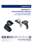
Adventure A10
Informationen für Therapeuten und Fachhändler
D
Adventure A10
Information for Therapists and DME Dealers
GB/US
Adventure A10
Informations pour les thérapeutes et les
commerçants spécialisés
F
Adventure A10
Informazioni per i terapisti e rivenditori
I
3
Neu!
New! Noveau! Nuovo! AB_Therap_A10_U1-4_02012008.indd1 1
Auflage
Edition
Edition
Edizione
02.01.2008 13:24:03 Uhr
AB_Therap_A10_U1-4_02012008.indd3 3
Adventure A10
Informationen für Therapeuten und Fachhhändler
D
Adventure A10
Information for Therapists and DME Dealers
GB/US
Adventure A10
Informations pur les thérapeutes et les
commerçants spécialisés
F
Adventure A10
Informazioni per i terapisti e rivenditori
I
02.01.2008 13:24:04 Uhr
Contents
1
Mechanical adjustments to the adventure
1.1
1.2
1.3
1.4
1.5
1.6
1.7
1.8
1.9
1.10
1.11
1.12
1.13
1.13.1
1.13.2
1.14
1.15
1.16
1.17
1.17.1
1.17.2
1.17.3
1.18
Armrest height adjustment
Armrest length adjustment
Armrest sideways adjustment
Backrest height adjustment only function seat
(comfort and standard upholstery)
Backrest angle of inclination adjustment
Function seat
Backrest angle of inclination adjustment
Standard seat
Seat length adjustment
Function seat (standard and comfort upholstery)
Leg support angle adjustment
Function seat
Leg support length adjustment
Standard and function seats
Leg support footrest angle adjustment
Function seat
Leg support footrest length adjustment
Standard and function seats
Interface instructions
Adjusting the chassis springing and damping
General information
Adjusting the rear springing
Setting the direction indicators
Setting the seat position
Function seat Setting the seat position
Standard seat
Fitting mudguards (optional extra)
Mudguards for the steering wheels
Mudguards for the powered wheels
Fitting rear reflectors
Control unit length adjustment
2
Settings on the control unit
General information regarding
programming mode
Driving programs
Changeable parameters
Activating service mode
Selection of the parameter settings
Indoor/Outdoor
Changing the parameters
Reverting to factory parameters settings
Parameter table
adventure Version 6 km/h
adventure Version 10 km/h
adventure Version 12 km/h
Fault detection / fault analysis codes
Fault indications on the display
2.1
2.2
2.3
2.4
2.5
2.6
2.7
2.8
2.8.1
2.8.2
2.8.3
2.9
2.10
AB_Therap_A10_GB_ms.indd 1
4
4
6
7
8
9
10
11
12
13
14
15
16
16
17
18
19
20
21
21
22
22
23
24
24
25
28
29
30
31
32
32
33
34
35
35
02.01.2008 11:40:28 Uhr
General notes
For the work procedures described in this information
bulletin you will need a set of hexagon socket keys
(Allen keys) 2.5 to 8 mm.
Ordering information for spare parts can be found in our
product manual.
alber offers specialist dealers for medical accessories
training courses for repairing the adventure and other alber
products.
Standard seat
The adventure wheelchair is now equipped with the functional or Recaro (optional) seating system and no longer with
the standard seat.
The information on the standard seat contained in this
brochure only refers to possible adjustments to the
adventure wheelchairs that are still equipped with the standard seat.
AB_Therap_A10_GB_ms.indd 2
02.01.2008 11:40:29 Uhr
1 Mechanical adjustments to the adventure
1.1 Armrest height adjustment
– Loosen the two screws [1] located in the side support.
– Push the armrest [2] to the desired height.
– Tighten the two screws [1] again.
2
1
1.2 Armrest length adjustment
– Loosen and remove the two screws [3] located in the side
support under the upholstery.
3
AB_Therap_A10_GB_ms.indd 3
3
02.01.2008 11:40:41 Uhr
– Pull the armrest [2] completely out of the holder [4].
– Loosen the two screws [6] located underneath the
upholstery [5].
�
– Push the moveable part [7] to the desired position.
– Tighten the two screws [6] again.
– Push the armrest [2] back into the holder [4].
2
4
6
76
– Screw the armrest [2] back onto the side support [8].
5
�
2
4
8
AB_Therap_A10_GB_ms.indd 4
2
02.01.2008 11:40:46 Uhr
1.3 Armrest sideways adjustment
9
– Tilt the entire seat [9] forwards.
– Loosen the two screws [10] located under the seat.
– Push the complete armrest [2] into the desired position.
�
�
2
!
AB_Therap_A10_GB_ms.indd 5
10
– Tighten the two screws [10] again.
– Fold the seat carefully back down onto the chassis.
Check the position of the armrest [2] in relation to the
direction indicators.
If the armrest bumps into the direction indicators, then
they will have to be adjusted too (see chapter 1.14).
02.01.2008 11:40:52 Uhr
1.4 Backrest height adjustment
Only Function seat (comfort and standard
upholstery)
11
– Remove the cushion from the backrest.
– Loosen and remove the 4 screws that hold the backrest to
the support bracket [11].
– On the inside of the backrest there are 3 holes in each of
two rows which are normally covered by the upholstery.
Feel for these holes with a sharp object.
12
12
12 12
– Select the hole [12] which will provide the desired height
for the backrest.
– With a sharp knife, cut an opening into the upholstery over
the chosen holes.
– As an alternative to a knife a soldering iron may also be
used. When the screw holes melt it should leave an even,
clean and heat-sealed border around the holes.
– Screw the backrest back onto the support bracket [11] in
the height position you have selected.
– Replace the cushion on the backrest.
AB_Therap_A10_GB_ms.indd 6
02.01.2008 11:40:58 Uhr
1.5 Backrest angle of inclination adjustment
Function seat
14
– Loosen the screws [13] in the support bracket.
11
– Push the entire backrest [14] to the desired angle of
inclination.
– Tighten the screws [13] again.
13
!
AB_Therap_A10_GB_ms.indd 7
13
By adjusting the angle of inclination, the height of the
backrest is also altered. It may be necessary to re-set the
height (see chapter 1.4).
02.01.2008 11:41:04 Uhr
1.6 Backrest angle of inclination adjustment
Standard seat
– Loosen and remove the four star grips [15].
– Pull or push the backrest [14] to the desired position.
– Screw the four star grips [15] back in and tighten them.
14
�
15
14
!
AB_Therap_A10_GB_ms.indd 8
By adjusting the angle of inclination, the height of the
backrest is also altered. It may be necessary to re-set the
height (see chapter 1.4).
02.01.2008 11:41:07 Uhr
10
1.7 Seat length adjustment
Function seat (standard and comfort
upholstery)
– Pull the cushion off the seat.
– Loosen and remove the four screws holding the seat.
– On the inside of the seat there are 5 holes in each of two
rows which are normally covered by the upholstery.
Feel for these holes with a sharp object.
16
16
– Select the hole [16] which will provide the desired seat
length for you.
– With a sharp knife, cut an opening into the upholstery over
the chosen holes.
– As an alternative to a knife a soldering iron may also be
used. When the screw holes melt it should leave an even,
clean and heat-sealed border around the holes.
– Screw the seat back on in the position you have selected.
– Replace the cushion on the seat.
AB_Therap_A10_GB_ms.indd 9
02.01.2008 11:41:11 Uhr
11
1.8 Leg support angle adjustment
Function seat
– Remove the leg support from the seat.
– Loosen the two screws [17] on the top of the leg support.
The connecting piece [18] is now freely moveable.
�
�
– Set the desired angle.
– Tighten the two screws [17] again.
– Attach the leg support back onto the seat.
17 17
18
AB_Therap_A10_GB_ms.indd 10
02.01.2008 11:41:14 Uhr
12
1.9 Leg support length adjustment
Standard and function seats
– Loosen the two screws [19] at the back of the leg support.
– Pull or push the lower part of the leg support [20] into the
desired position.
– Firmly tighten the two screws [19] again.
�
�
19
20
AB_Therap_A10_GB_ms.indd 11
02.01.2008 11:41:19 Uhr
1.10 Leg support footrest angle adjustment
Function seat
13
– Loosen the screws [21] on both sides at the lower end of
the leg support.
– Push the retainer [22] into the desired position.
– Check the retainer and with it the angle of the footrest.
If necessary, the retainer [22] may have to be moved again. – If the retainer and with that the desired angle of the footrest are set correctly, then tighten the screws [21] again.
�
�
21
22
AB_Therap_A10_GB_ms.indd 12
22
02.01.2008 11:41:23 Uhr
14
1.11 Leg support footrest length adjustment
Standard and function seats
– Loosen the three screws [23] underneath the footrest.
– The length can be adjusted by inserting the screws in one
of the three sets of holes A, B or C.
A
B
C
– Screw the footrest [24] into the desired position.
23
�
�
23 23
24
AB_Therap_A10_GB_ms.indd 13
02.01.2008 11:41:25 Uhr
15
1.12 Interface instructions
The interface [25] located on the chassis is for the
attachment of a peripheral module for the control of external
drives.
�
The cover [26] prevents the interface getting dirty or
damaged and must only be removed if a device is to be
attached.
�
25
26
AB_Therap_A10_GB_ms.indd 14
02.01.2008 11:41:30 Uhr
16
1.13 Adjusting the chassis springing and
damping
1.13.1 General information
When the adventure is first delivered, the chassis is optimally
adjusted to the respective weight of the user and, as a rule,
does not need any further adjustment. If a second-hand
device is to be used or the body weight of the wheelchair
driver should change significantly, then the chassis should
be readjusted.
Spring
Feder
(blue, schwarz
black or oder
red) rot)
(blau,
Damping
Dämpferelement
element
The spring hardness is principally responsible for the degree
of comfort of the chassis and should be selected to match the
weight of the wheelchair driver. Basically there are three
different degrees of spring hardness available for the respective weight categories:
Blue springs:
Wheelchair drivers with up to 80 kg body weight
Black springs:
Wheelchair drivers with from 81 to 120 kg body weight
Red springs:
Wheelchair drivers with from 121 to 140 kg body weight
Determine into which weight category the wheelchair driver
falls and whether the colour of the installed springs corresponds. Under some circumstances the springs will have to be
exchanged or readjusted. This must only be undertaken by
an authorised and trained dealer or by the alber Service Center (phone +49 (0) 800 90 96 250).
The rear springs are principally responsible for the comfort
of the ride and they can be finely set thanks to the adjustable spring preload. The front springs need to be readjusted
only in rare cases (spring replacement necessary, significant
weight change of the wheelchair driver) and should, as a rule,
remain in the position set in the factory.
AB_Therap_A10_GB_ms.indd 15
02.01.2008 11:41:31 Uhr
17
1.13.2 Adjusting the rear springing
Prior to adjusting the springing the batteries must be
removed (see illustration) so that the spring/damper element
is completely load-free.
The preload of the rear springs [27] can be set with the help
of several differently coloured spacer gauges that can be
obtained from alber or with a conventional one.
– Place the spacer gauge [28] against the spring [27] as
shown in the diagram.
The spacer gauge [28] must make contact with the spring
buffer [29].
– Turn the adjusting wheel [30] on the spring.
nt
fro
27
k
bac
29
28
– You have set the correct spacing, as taken from the table
below, when the adjustment wheel [30] makes contact with
the spacer gauge. 30
!
Make sure that you set the same figure for both rear
springs.
The maximum additional load of 140 kg should never be
exceeded.
Spacer gauge
Identifier:
blue (for blue springs)
To 50 kg
84 mm
To 60 kg
83 mm
To 70 kg
82 mm
To 80 kg
80 mm
Identifier:
black (for black springs)
To 90 kg
83 mm
To 100 kg
81 mm
To 110 kg
79 mm
To 120 kg
77 mm
Identifier:
red (for red springs)
To 130 kg
79 mm
To 140 kg
77 mm
!
Please inform the wheelchair occupant that a readjustment of the front* and rear suspensions will be necessary
if he or she gains or loses substantially in weight (for
example, due to a particular illness).
If the user gains a large amount of weight there is a danger
that the chassis may be damaged; if there is a large loss in
weight the comfort during driving is reduced.
* To carry out installation work and adjustments to the front
part of the chassis, prior training by alber is a prerequisite.
Please contact us for this.
AB_Therap_A10_GB_ms.indd 16
02.01.2008 11:41:35 Uhr
18
1.14 Setting the direction indicators
31
When the armrest is adjusted sideways (see chapter 1.3), it
may prove necessary to re-position the two direction
indicators [31].
31
– Loosen the two screws [32].
– Pull or push the direction indicator [31] into the desired
position. There should always be a small space
(approx. 5 mm) between the direction indicator [31] and
armrest.
�
�
– Tighten the two screws [32] again.
31
AB_Therap_A10_GB_ms.indd 17
32
02.01.2008 11:41:35 Uhr
19
1.15 Setting the seat position
Function seat
– Loosen the screws [34] on both sides of the holder stay
[33].
34
33
– Pull or push on the holder stay [33] so that the entire seat
holder moves into the desired position.
– Firmly tighten the two screws [34] on both sides of the holder stay [33] again.
AB_Therap_A10_GB_ms.indd 18
02.01.2008 11:41:36 Uhr
20
1.16 Setting the seat position
Standard seat
35
33
– Loosen and remove the screws [35] on both sides of the
holder stay [33].
– Place the holder stay [33] against the hole positions
desired.
– Screw the holder stay [33] tight again using the screws
[35].
AB_Therap_A10_GB_ms.indd 19
02.01.2008 11:41:40 Uhr
21
1.17 Fitting mudguards (optional extra)
1.17.1 Mudguards for the steering wheels
– Thoroughly clean the connecting surface of the fork. It
must be free of all dirt and grease.
– Remove the self-adhesive foil [36] from the mudguard.
36
– Push the mudguard [37] under the fork of the steering
wheel. Make sure it is positioned properly.
– Press the mudguard [37] firmly against the steering wheel
fork for a short time.
�
AB_Therap_A10_GB_ms.indd 20
37
02.01.2008 11:41:42 Uhr
22
1.17.2 Mudguards for the powered wheels
– Position the angle bracket of the mudguard [38] on the
holder [39], as shown in the diagram.
– Screw the mudguard [38] onto the holder [39].
39
38
1.17.3 Fitting rear reflectors
– Remove the adhesive foil [40] from the back of the rear
reflectors [41].
– Stick the rear reflectors [41], as shown in the diagram, onto
the back of the batteries (the wording TOP/DOT/TOP must
be at the top)
40
41
41
!
AB_Therap_A10_GB_ms.indd 21
Driving with mudguards and without rear reflectors is not
permitted.
02.01.2008 11:41:46 Uhr
23
1.18 Control unit length adjustment
– Loosen the two screws [42] in the bracket [43] situated
underneath the armrest.
42
– Push the bracket holding the control unit to the desired
position.
– Tighten the two screws [42] again.
AB_Therap_A10_GB_ms.indd 22
02.01.2008 11:41:49 Uhr
2 Settings on the control unit
24
2.1 General information regarding programming
mode
In order to meet the different requirements of customers and
the various sorts of disablement, the adventure provides a
wide range of variable driving parameters.
Programming can be carried out directly via the control unit
without any additional device. Only a programming key,
which is delivered with every new adventure, is needed.
Programming key
Programmierschlüssel
!
For safety reasons, the programming key should not be
given to the user. Driving parameters must only be
changed by qualified persons (e.g. a therapist, a specialist
dealer).
After the program has been changed, a trial run should be
undertaken, supervised by a qualified person, to ensure
that the user can cope with the new driving
characteristics.
2.2 Driving programs
There are two driving programs available for the adventure
– Indoor and Outdoor modes. To a great extent, both modes
can be programmed independently of each other, so that
travel indoors can be based on different parameters from
travel outdoors. It is also possible to make individual
settings to reflect the state of health and disablement of the
wheelchair occupant. The essential differences between the two modes are:
– In Outdoor mode the wheel at the outside of a curve is
accelerated, resulting in nimble driving conduct
– In Indoor mode the wheel at the inside of a curve is braked,
resulting in driving conduct that is tolerant and predictable
AB_Therap_A10_GB_ms.indd 23
02.01.2008 11:41:50 Uhr
25
2.3 Changeable parameters
The following parameters may be adjusted to user requirements directly via the control unit, without any external
programming device:
Select parameter set Indoor / Outdoor
– The adventure allows the parameters for Indoor and Outdoor use to be programmed independently of each other.
For example, slow and fine for indoors and with maximum
speed and precise straight ahead travel for outdoors (factory setting).
– The following parameters change both for Indoor and Outdoor mode when they are re-programmed and they cannot
be saved as different for the two modes:
– 9 [Self switch off time]
– 10 [Driving signal displacement] always apply to both – 12 [change of direction joystick] Indoor and Outdoor
– Can also be set according to the state of health or mind of
the user, e.g. weak or strong constitution.
Maximum speed forwards
– Determines the maximum attainable speed.
– Can be set in 5 steps (20 %, 40 %, 60 %, 80 % and 100 %).
– Reduction of speed is recommended for beginners or for
use exclusively indoors.
– Reduction also sensible for older (geriatric) users.
Maximum speed backwards
– Determines the maximum attainable speed.
– For safety reasons, it is limited to a maximum of 70 % of
the set maximum speed forwards.
– Reduction recommended if a very slow speed is desired
(e.g. for drivers with bad coordination, older users and for
travel indoors).
Acceleration time
– Time taken to reach the maximum set speed.
– Also perceived by the user as “Reaction”
(prompt / sluggish).
– Reduction for tremor or ataxia.
– Increase to enable small obstructions to be overcome
more easily at low speeds (e.g. thresholds indoors).
Slow down time
– The time taken for braking from the maximum speed to the
desired speed or to a standstill.
– Reduction if very gentle driving is required at lower speeds
(e.g. for users with diminished upper body / trunk
stability).
– Increase if very precise driving is required at lower speeds
(e.g. confined living room) or rapid reaction is desired.
AB_Therap_A10_GB_ms.indd 24
02.01.2008 11:41:53 Uhr
26
Turning speed
– Determines the maximum speed at which an arc of a circle
or curve is travelled at.
– Reduction produces more stable straight forward driving
at high speeds; at low speeds sluggish / tolerant.
– Increase at lower speeds (indoors) improves travel round
tight curves; at higher speeds more nervous / rapid reaction.
Turning acceleration / slow down (sensitivity)
– Time taken to attain maximum turning speed.
– Also usually described as sensitivity or reaction.
– 5 bars = rapid reaction / acceleration.
– Reduction down to 1 or 2 bars to adjust for tremor or
ataxia.
Audible signals
– Switches audible signal on / off, for example a beep when
error messages appear or for battery state-of-charge
warning.
Braking onset
– The time delay until the electromagnetic parking brakes
are applied after the last issuance of a driving command
(displacement of the joystick).
– Without time delay (1 second): if an immediate safe stand
is required (e.g. on approaching lightly sloping kerbs /
ledges).
– With time delay (30 seconds): avoids constant braking
onset – undesirable “clicking” noise prevented.
Self switch off time
– The time until the adventure switches itself off (to save the
battery).
– May be set from 1 to 5 hours.
Joystick through
– Attaining the maximum speed dependent on joystick displacement
– Setting to 1 bar (minimum) means that: after 50% of the
way (half displacement of the joystick) the maximum
speed will already be reached. A further displacement
beyond that does not increase the speed!
– Makes sense for those with little muscular strength (MD),
with restricted arm and / or hand functions or when used
as mouth or chin controller
– Setting to 5 bars: the maximum speed is reached when the
joystick is fully displaced.
AB_Therap_A10_GB_ms.indd 25
02.01.2008 11:41:57 Uhr
Battery capacity
– To provide most exact battery capacity indication, the
battery size can be adjusted for 2 different types of the
battery pack.
– Factory pre-set according to battery size ordered.
27
Change of direction joystick
Particularly useful for users who can only displace the
joystick in certain directions (e.g. can merely pull it) or if the
control unit is fitted in the opposite direction (e.g. with a
therapeutic table).
Possible changes:
– Change the joystick setting to the actual direction of
movement
– Change forwards / backwards
– Change left / right
– Change both joystick settings
Attention!
With changed movement parameter 12 “change of direction
joystick” the adventure may only be operated with the bowtype handle for protection against ramming for control unit
(optional accessory)!
On accidentally bumping into an obstacle, (e.g. a tabletop)
without protection against ramming, the joystick will be
displaced even more. Consequently the driver will not be
able to get out of this situation single-handedly. He will be
effectively pinned in. If such a situation should arise, all that
the driver can do is to switch off the adventure.
Joystick
displacement
Obstruction:
e.g. table edge
Direction
of movement
!
Caution!
After changing this driving parameter the user must be
given time to adjust to the new driving characteristics very
slowly and under professional supervision (at minimum
speed).
Display option
Setting options for various displays on the screen.
Possible settings:
– Normal display
– Driving speed
– Daily kilometre counter
Note:
By pressing the menu button for approx. 3 seconds the daily
kilometre counter is set to “zero”.
AB_Therap_A10_GB.indd 27
11.12.2008 12:11:09 Uhr
Batt
· To
ba
ad
· Fac
28
Speed reduction
This parameter can only be altered in conjunction with the
attachment of a periphery module.
Chassis with short or long rocker
– Setting 1 bar: More gentle braking (Setting only admissible for chassis with long wheelbase)
– Setting 5 bars: Standard setting (without additional functions)
Lighting/Direction indicators
– Setting 1 bar: functions deactivated
– Setting 5 bars: functions activated
2.4 Activating service mode
In order to activate service mode you must first insert the
programming key [1] into the opening [2] underneath the
control unit.
2
1
Then switch the adventure on by pressing the On / Off button
[3]. On the display screen [4] the symbol , the code “0“
and a single bar will be shown.
4
3
AB_Therap_A10_GB_ms.indd 27
02.01.2008 11:42:03 Uhr
29
2.5 Selection of the parameter settings Indoor / Outdoor
Now you must choose the mode which you wish to change.
Initially the mode in which you currently are will be shown.
Outdoor Mode
The following indicators apply:
One bar display
=
Outdoor mode
Two bars display
=
Indoor mode
Indoor Mode
To switch from Outdoor to Indoor mode, push the joystick
upwards once – the second bar will appear.
To switch from Indoor to Outdoor mode, push the joystick
downwards once – the second bar will disappear.
AB_Therap_A10_GB_ms.indd 28
02.01.2008 11:42:03 Uhr
30
2.6 Changing the parameters
After you have established the mode which you wish to
change, you can begin with the individual programming.
By displacing the joystick to the left or right the various
parameters described in chapter 2.3 may be set.
The following apply:
Displacement to the right: number code (1-15) is increased
(change to the next highest parameter).
Displacement to the left: number code (1-15) is decreased
(change to the next lowest parameter).
Displacement upwards: number of bars shown is increased;
the currently selected parameter is increased or accepted.
AB_Therap_A10_GB_ms.indd 29
02.01.2008 11:42:06 Uhr
Displacement downwards: number of bars shown is
decreased; the currently selected parameter is decreased or
deactivated.
!
31
Parameters, codes and possible settings can be found in
the table in chapter 2.8
When programming is complete:
– Pull the programming key [1] out of its location underneath
the control unit.
– The newly programmed driving characteristics are saved
automatically.
– Carry out a trial run to check out the newly programmed
driving characteristics.
1
2.7 Reverting to factory parameter settings
The parameters as set in the factory may be reverted to at
any time as follows:
– Switch the adventure off.
– Insert the programming key [1] into the opening [2] located
underneath the control unit.
– Pull the joystick [5] back and hold it in this position.
2
1
– Then switch the adventure on again by pressing the On /
Off button [3].
4
3
– Wait for approx. 2 seconds until the factory programming
is automatically restored.
– On the display [4] the information shown on the left will
appear.
– Pull the programming key [1] out of the control unit again.
– The adventure can now be operated again with the parameters as set in the factory.
5
AB_Therap_A10_GB_ms.indd 30
02.01.2008 11:42:11 Uhr
32
2.8 Parameter table
2.8.1 adventure version 6 km/h
(Factory settings are marked in bold)
Parameter
Code
Setting
Nominal value
Driving program 0
1 bar
2 bars
Outdoor
Indoor
Parameter
Code
Display
indication
Indoor settings
Outdoor settings
Maximum 1
speed forwards
1 bar
2 bars
3 bars
4 bars
5 bars
1,3 km/h
2,5 km/h
3,8 km/h
5,0 km/h
6,0 km/h 1,3 km/h
2,5 km/h
3,8 km/h
5,0 km/h
6,0 km/h
Maximum speed 2
reverse
1 bar
2 bars
3 bars
4 bars
5 bars
1,8 km/h 2,4 km/h
3,0 km/h
3,6 km/h
4,2 km/h
1,8 km/h
2,4 km/h
3,0 km/h
3,6 km/h
4,2 km/h
Acceleration 3
time
1 bar
2 bars
3 bars
4 bars
5 bars
3,2 seconds
2,8 seconds
2,3 seconds
1,8 seconds
1,4 seconds
3,2 seconds
2,8 seconds
2,3 seconds
1,8 seconds
1,4 seconds
Slow down time 4
1 bar
2 bars
3 bars
4 bars
5 bars
3,7 seconds
3,2 seconds
2,8 seconds
2,3 seconds
1,8 seconds
3,7 seconds
3,2 seconds
2,8 seconds
2,3 seconds
1,8 seconds
Turning speed
5
1 bar
2 bars
3 bars
4 bars
5 bars
22 % (slow)
25 %
28 %
31 %
34 % (fast)
22 % (slow)
25 %
28 %
31 %
34 % (fast)
Turning 6
acceleration /
deceleration (sensitivity)
1 bar
2 bars
3 bars
4 bars
5 bras
0,09 seconds (slow)
0,06 seconds
0,05 seconds
0,04 seconds
0,03 seconds (fast)
0,19 seconds (slow)
0,13 seconds
0,09 seconds
0,08 seconds
0,06 seconds (fast)
Audible signals
7
1 bar
5 bars
Deactivated
Activated
Deactivated
Activated
Braking onset
8
1 bar
5 bars
Time delayed by 30 seconds
Immediate (1 second)
Time delayed by 30 seconds
Immediate (1 second)
Self switch off 9
time
1 bar
2 bars
3 bars
4 bars
5 bars
1 hour
2 hour
3 hour
4 hour
5 hour
1 hour
2 hour
3 hour
4 hour
5 hour
Joystick throw
10
joystick
1 bar
5 bars
50 %
100 %
50 %
100 %
Battery capacity 11
1 bar
5 bars
22 Ah Multipower
17 Ah Panasonic
22 Ah Multipower
17 Ah Panasonic
Change of 12
1 bar
direction 2 bars
joystick
3 bars
4 bars
No change
Forwards / backwards changed
Left / right changed
Forwards / backwards and left / right changed
No change
Forwards / backwards changed
Left / right changed
Forwards / backwards and
left / right changed
Display option 13
Normal display
Driving speed
Daily kilometres counter
Normal display
Driving speed
Daily kilometres counter
1 bar
2 bars
3 bars
Speed reduction 14
Only in conjunction with periphery module Only in conjunction with periphery module
Chassis with 15
1 bar
long or short wheelbase
5 bars
More gentle braking (Setting only
admissible for chassis with long wheelbase)
Standard setting (without additional function)
More gentle braking (Setting only
admissible for chassis with long
wheelbase) Standard setting (without additional function)
Lighting/Direction 16
indicator
functions deactivated
functions activated
functions deactivated
functions activated
AB_Therap_A10_GB.indd 32
1 bar
5 bars
11.12.2008 12:11:17 Uhr
33
2.8.2 adventure version 10 km/h*
* Not available in the USA
(Factory settings are marked in bold)
Parameter
Code
Setting
Nominal value
Driving program 0
1 bar
2 bars
Outdoor
Indoor
Parameter
Code
Display
indication
Indoor settings
Outdoor settings
Maximum speed 1
forwards
1 bar
2 bars
3 bars
4 bars
5 bars
2,0 km/h
4,0 km/
6,0 km/h
8,0 km/h
10,0 km/h
2,0 km/h
4,0 km/h
6,0 km/h
8,0 km/h
10,0 km/h
Maximum speed 2
reverse
1 bar
2 bars
3 bars
4 bars
5 bars
1,8 km/h 2,4 km/h
3,0 km/h
3,6 km/h
4,2 km/h
1,8 km/h
2,4 km/h
3,0 km/h
3,6 km/h
4,2 km/h
Acceleration 3
time
1 bar
2 bars
3 bars
4 bars
5 bars
8,0 seconds
6,9 seconds
5,7 seconds
4,6 seconds
3,4 seconds
8,0 seconds
6,9 seconds
5,7 seconds
4,6 seconds
3,4 seconds
Slow down time 4
1 bar
2 bars
3 bars
4 bars
5 bars
9,2 seconds
8,0 seconds
6,9 seconds
5,7 seconds
4,6 seconds
9,2 seconds
8,0 seconds
6,9 seconds
5,7 seconds
4,6 seconds
Turning speed
5
1 bar
2 bars
3 bars
4 bars
5 bars
14 % (slow)
16 %
18 %
20 %
21 % (fast)
14 % (slow)
16 %
18 %
20 %
21 % (fast)
Turning 6
acceleration /
deceleration
(sensitivity)
1 bar
2 bars
3 bars
4 bars
5 bars
0,08 seconds (slow)
0,05 seconds 0,04 seconds 0,03 seconds
0,025 seconds (fast)
0,19 seconds (slow)
0,13 seconds
0,09 seconds
0,08 seconds
0,06 seconds (fast)
Audible signals
7
1 bar
5 bars
Deactivated
Activated
Deactivated
Activated
Braking onset
8
1 bar
5 bars
Time delayed by 30 seconds
Immediate (1 second)
Time delayed by 30 seconds
Immediate (1 second)
Self switch 9
off time
1 bar
2 bars
3 bars
4 bars
5 bars
1 hour
2 hours
3 hours
4 hours
5 hours
1 hour
2 hours
3 hours
4 hours
5 hours
Joystick throw
10
joystick
1 bar
5 bars
50 %
100 %
50 %
100 %
Battery capacity 11
1 bar
5 bars
22 Ah Multipower
17 Ah Panasonic
22 Ah Multipower
17 Ah Panasonic
Change of 12
1 bar
direction 2 bars
joystick
3 bars
4 bars
No change
Forwards / backwards changed
Left / right changed
Forwards / backwards and left / right changed
No change
Forwards / backwards changed
Left / right changed
Forwards / backwards and
left / right changed
Display option 13
Normal display
Driving speed
Daily kilometres counter
Normal display
Driving speed
Daily kilometres counter
1 bar
2 bars
3 bars
Speed reduction 14
Only in conjunction with periphery module Only in conjunction with periphery module
Chassis with 15
1 bar
long or short wheelbase
5 bars
More gentle braking (Setting only
admissible for chassis with long wheelbase)
Standard setting (without additional function)
More gentle braking (Setting only
admissible for chassis with long
wheelbase) Standard setting (without additional function)
Lighting/Direction 16
indicator
functions deactivated
functions activated
functions deactivated
functions activated
AB_Therap_A10_GB.indd 33
1 bar
5 bars
11.12.2008 12:11:17 Uhr
34
2.8.3 adventure version 12 km/h
(Factory settings are marked in bold)
Parameter
Code
Setting
Nominal value
Driving program 0
1 bar
2 bars
Outdoor
Indoor
Parameter
Code
Display
indication
Indoor settings
Outdoor settings
Maximum 1
speed forwards
1 bar
2 bars
3 bars
4 bars
5 bars
2,4 km/h
4,8 km/h
7,2 km/h
9,6 km/h
12,0 km/h
2,4 km/h
4,8 km/h
7,2 km/h
9,6 km/h
12,0 km/h
Maximum speed 2
reverse
1 bar
2 bars
3 bars
4 bars
5 bars
1,8 km/h 2,4 km/h
3,0 km/h
3,6 km/h
4,2 km/h
1,8 km/h
2,4 km/h
3,0 km/h
3,6 km/h
4,2 km/h
Acceleration
3
time
1 bar
2 bars
3 bars
4 bars
5 bars
8,8 seconds
7,6 seconds
6,3 seconds
5,1 seconds
3,8 seconds
8,8 seconds
7,6 seconds
6,3 seconds
5,1 seconds
3,8 seconds
Slow down 4
time
1 bar
2 bars
3 bars
4 bars
5 bars
10,1 seconds
8,8 seconds
7,6 seconds
6,3 seconds
5,1 seconds
10,1 seconds
8,8 seconds
7,6 seconds
6,3 seconds
5,1 seconds
Turning speed
5
1 bar
2 bars
3 bars
4 bars
5 bars
12 % (slow)
13 %
15 %
16 %
18 % (fast)
12 % (slow)
13 %
15 %
16 %
18 % (fast)
Turning
6
acceleration /
deceleration
(sensitivity)
1 bar
2 bars
3 bars
4 bars
5 bars
0,08 seconds (slow)
0,05 seconds
0,04 seconds
0,03 seconds
0,025 seconds (fast)
0,11 seconds (slow)
0,08 seconds
0,07 seconds
0,06 seconds
0,05 seconds (fast)
Audible signals
7
1 bar
5 bars
Deactivated
Activated
Deactivated
Activated
Braking onset
8
1 bar
5 bars
Time delayed by 30 seconds
Immediate (1 second)
Time delayed by 30 seconds
Immediate (1 second)
Self switch off 9
time
1 bar
2 bars
3 bars
4 bars
5 bars
1 hour
2 hours
3 hours
4 hours
5 hours
1 hour
2 hours
3 hours
4 hours
5 hours
Joystick throw
10
joystick
1 bar
5 bars
50 %
100 %
50 %
100 %
Battery capacity 11
1 bar
5 bars
22 Ah Multipower
17 Ah Panasonic
22 Ah Multipower
17 Ah Panasonic
Change of 12
1 bar
direction 2 bars
joystick
3 bars
4 bars
No change
Forwards / backwards changed
Left / right changed
Forwards / backwards and
left / right changed
No change
Forwards / backwards changed
Left / right changed
Forwards / backwards and
left / right changed
Display option 13
Normal display
Driving speed
Daily kilometres counter
Normal display
Driving speed
Daily kilomtres counter
1 bar
2 bars
3 bars
Speed reduction 14
Only in conjunction with periphery module Only in conjunction with periphery module
Chassis with 15
1 bar
long or short wheelbase
5 bars
More gentle braking (Setting only
admissible for chassis with long wheelbase)
Standard setting (without additional function)
More gentle braking (Setting only
admissible for chassis with long
wheelbase) Standard setting (without additional function)
Lighting/Direction 16
indicator
functions deactivated
functions activated
functions deactivated
functions activated
AB_Therap_A10_GB.indd 34
1 bar
5 bars
11.12.2008 12:11:17 Uhr
35
2.9 Fault detection / fault analysis codes
The adventure software is equipped with an automatic fault
detection and analysis system. If a fault is detected in the
system, it is shown on the LCD display of the control unit by
means of a code number and symbol (see table below).
Many faults occur due to badly or incompletely charged
batteries (code number 2). As the powered wheels are disengaged for manual operation, the error code ”Brake symbol
flashes“ (left or right powered wheel disengaged) also
occurs frequently. This can be corrected by engaging the
wheels again (see Operating Instructions).
2.10 Fault indications on the display
Faults that may occur on your adventure are indicated on
the display of the control unit. The following indications are
possible:
Display indication
(letters flash)
Control unit symbol flashes
Fault description
What to do
Hardware fault on
control panel
Excessive battery
voltage calibration or
EEPROM programming
error
Replace control unit
PCB or control unit
EEPROM faulty or
wrongly coded
1. Realize works setting
2. Replace control unit
if 1. is unsuccessful!
Battery voltage range
error
1. Battery defective.
Check 2 batteries by
inserting separately
in central position.
Check/Replace fuses
on battery or replace
battery completely if
battery is defective!
2. Hardware fault on
control unit. Replace
PCB / control unit!
3. Battery fully charged.
Overvoltage error when
driving uphill. Remedy
approx. 0.5 km uphill!
4. Battery flat! Charge
storage batteries
Exclamation mark lit up
Code 0
Control unit symbol flashes
Exclamation mark flashes
Code 1
Control unit symbol flashes
Exclamation mark lit up
Code 2
AB_Therap_A10_GB_ms.indd 34
02.01.2008 11:42:16 Uhr
36
Drive symbol flashes
Uneven drive coding
Left and right drive
uneven. 6 km/h with
10 or 12 km/h or vice
versa!
Fit identical drives on
both sides
No communication with
“left“ drive
L4 has priority over R4!
For L4/R4: Switch
wheels from right to
left! (caution, as intact
wheel can also fail as a
result of switch!)
- error L4 is transferred if left wheel is
defective!
- error R4 is usually in
right wheel! (always
check 40A fuses in
interface!) Other error
sources: Interface or
connection cables/contacts (replace interface
/ send chassis to works
in this case!)
No communication with
“right“ drive
Identical to Code L4
Communication fault
Check communication
components:
1. control unit
2. powered wheel left
3. powered wheel right
4. interface
Communication fault
1. P-module defective
(replace P-module PCB
or P-module)
2. Sub-D plug or cable
on P-module
(replace cable with plug
or P-module)
3. Sub-D socket or cable
(replace interface)
Exclamation mark lit up
Code 3
Drive symbol flashes
Exclamation mark lit up
Letter »L« flashes
Code L4
Drive symbol flashes
Exclamation mark lit up
Letter »R« flashes
Code R4
Interface symbol flashes
Exclamation mark lit up
Letter »S« flashes
Code S4
Interface symbol flashes
Exclamation mark
lit up
Letter »P« flashes
Code P4
Control unit symbol flashes
Exclamation mark lit up
Code 5
AB_Therap_A10_GB_ms.indd 35
Defective drive signal
transmitter in the
control unit
Joystick fault on control
unit
1. Joystick fault: Replace joystick or control
unit!
2. Electronics fault:
Replace PCB or control
unit!
02.01.2008 11:42:21 Uhr
Battery symbol flashes
Exclamation mark flashes
Code 6
Battery configuration
error and/or detection
faulty
(L6 = left battery pack,
R6 = right battery pack)
Contact your specialist
supplier or the alber
Service Center if the
error code continues to
be displayed
Control unit symbol flashes
No communication with
special control
Connection to special
control interrupted!
Driving with control
unit possible after
reactivation on control
unit!
Sub-D socket or cable
on interface defective:
Replace cable with
socket or interface!
Check special control
connection cable/special control!
Drive unit not compatible with control unit
System can be coded
as 6 km/h, but 10 or 12
km/h drives are fitted
(or vice versa)!
Fit power-assisted
wheels permitted for
top speed limit.
CPU fault on
control unit
Replace control unit
PCB or control unit
RAM error on
control panel
Replace control unit
PCB or control unit
ROM horizontal parity
error on control unit
Replace control unit
PCB or control unit
Interface symbol flashes
Exclamation mark lit up
Code 7
Control unit symbol flashes
Drive symbol flashes
Exclamation mark lit up
Code 8
Control unit
symbol flashes
1. Driving with 1 battery
pack: battery not inserted in central position!
2. Driving with 2 battery
packs:
- one battery set
defective
- battery fuse (40A)
defective
- battery detection in
interface defective
Rapid error diagnosis
by inserting the batteries consecutively in the
middle position!
37
Exclamation mark
lit up
Code 9
Control unit
symbol flashes
Exclamation mark
lit up
Code 10
Control unit
symbol flashes
Exclamation mark
lit up
Code 11
AB_Therap_A10_GB_ms.indd 36
02.01.2008 11:42:25 Uhr
38
Drive symbol flashes
„Left“drive hardware/
system error
Drive must be checked
at alber works
„Right“ drive hardware/
system error
Drive must be checked
at alber works
“Left“ drive overload
switch-off
Brief overloading
deactivates temperature! System is operationally ready again
after deactivation and
reactivation
“Right“ drive overload
switch-off
Brief overloading
deactivates temperature! System is operationally ready again
after deactivation and
reactivation
“Left“ drive battery
voltage range error
Cable fault between
battery, interface and
drive (can be one of the
components!)
Switch wheels!
1. Fault transferred! ->
Fault in wheel
1. Fault not transferred!
-> Interface or fuse
(interface or battery)
cable fault
“Right“ drive battery
voltage range error
Cable fault between
battery, interface and
drive (can be one of the
components!)
Switch wheels!
1. Fault transferred! ->
Fault in wheel
1. Fault not transferred!
-> Interface or fuse
(interface or battery)
cable fault
Exclamation mark lit up
Letter »L« flashes
Code L0
Drive symbol flashes
Exclamation mark lit up
Letter »R« flashes
Code R0
Drive symbol flashes
Temperature symbol lit up
Exclamation mark lit up
Letter »L« flashes
Code L1
Drive symbol flashes
Temperature symbol lit up
Exclamation mark lit up
Letter »R« flashes
Code R1
Drive symbol flashes
Exclamation mark lit up
Letter »L« flashes
Code L2
Drive symbol flashes
Exclamation mark lit up
Letter »R« flashes
Code R2
AB_Therap_A10_GB_ms.indd 37
02.01.2008 11:42:30 Uhr
Drive symbol flashes
“Left“ drive operating
temperature switch-off
Drive overheating deactivates temperature!
Allow system to
cool! (Cooling period
depends on ambient
temperature!)
“Right“ drive operating
temperature switch-off
Drive overheating deactivates temperature!
Allow system to
cool! (Cooling period
depends on ambient
temperature!)
Temperature symbol lit up
Exclamation mark lit up
39
Letter »L« flashes
Code L3
Drive symbol flashes
Temperature symbol lit up
Exclamation mark lit up
Letter »R« flashes
Code R3
Temperature symbol flashes “Left“ drive operating
temperature warning
Exclamation mark flashes
Battery capacity display
illuminates
Drive overheating
warning!
Reduce load, otherwise
temp. system shutdown
with error L3/R3!
Code L
Temperature symbol flashes “Right“ drive operating
temperature warning
Exclamation mark flashes
Battery capacity display
illuminates
Drive overheating
warning!
Reduce load, otherwise
temp. system shutdown
with error L3/R3!
Code R
Drive symbol flashes
Wheel code/“Left“
electronic drive error
Wrong electronics in
drive (e.g. 6 km/h PCB
in 12 km/h machine) or
wrong drive code!
1. Replace electronics
2. Edit drive code (only
possible in alber works)
Wheel code/“Right“
electronic drive error
Wrong electronics in
drive (e.g. 6 km/h PCB
in 12 km/h machine) or
wrong drive code!
1. Replace electronics
2. Edit drive code (only
possible in alber works
Exclamation mark
lit up
Letter »L« flashes
Code L5
Drive symbol flashes
Exclamation mark
lit up
Letter »R« flashes
Code R5
AB_Therap_A10_GB_ms.indd 38
02.01.2008 11:42:35 Uhr
40
Interface symbol flashes
Hardware fault on
interface
Replace interface PCB
or interface
Exclamation mark lit up
Letter »S« flashes
Code S0
,
Interface symbol flashes
CPU fault on interface
Replace interface PCB
or interface
RAM error on interface
Replace interface PCB
or interface
ROM horizontal parity
error on interface
Replace interface PCB
or interface
»Left« indicator light
defective
1. Defective indicator
light (change bulb)
2. Check cable for
defects
3. Fault on interface
PCB
4. F4 fuse (3A) on interCode S5
5. No lighting/no indicator light: deactivate
with parameter 16
Exclamation mark
lit up
Letter »S« flashes
Code S1
Interface symbol flashes
Exclamation mark
lit up
Letter »S« flashes
Code S2
Interface symbol flashes
Exclamation mark
lit up
Letter »S« flashes
Code S3
Interface symbol flashes
Exclamation mark
flashes
Letter »S« flashes
Code S5
Interface symbol flashes
Exclamation mark
flashes
Letter »S« flashes
Code S6
AB_Therap_A10_GB_ms.indd 39
»Right« indicator light
defective
1. Defective indicator
light (change bulb)
2. Check cable for
defects
3. Fault on interface
PCB
4. F4 fuse (3A) on interface burnt out
5. No lighting/no indicator light: deactivate
with parameter 16
02.01.2008 11:42:39 Uhr
Complete seat unit*
flashes
Interface symbol flashes
Hardware fault on
peripheral module
(different drive and/or
relay actuation)
Replace P-module PCD
or P-module
CPU fault on peripheral
module
Replace P-module PCD
or P-module
RAM error on peripheral module
Replace P-module PCD
or P-module
ROM horizontal parity
error on peripheral
module
Replace P-module PCD
or P-module
Erroneous potentiometer position feedback
signal
(only applies to drives
with feedback signal)
1. Drive sensor defective! (Test by
changing connections
of different drives to Pmodule / Should only
be entrusted to authorized skilled personnel)
2. Drive/P-module cable
fault! Test by
changing connections
of different drives to Pmodule / Should only
be entrusted to authorized skilled personnel)
3. Defective P-module
PCB
Multiple occupancy of
»left« and/or »right«
indicator key function
Programming error on
P-module, replace Pmodule
41
Exclamation mark
lit up
Letter »P« flashes
Code P0
Complete seat unit*
flashes
Interface symbol
flashes
Exclamation mark
lit up
Code P1
Complete seat unit*
flashes
Interface symbol
flashes
Exclamation mark
lit up
Code P2
Complete seat unit*
flashes
Interface symbol
flashes
Exclamation mark
lit up
Code P3
Complete seat unit*
flashes
Interface symbol
flashes
Exclamation mark
lit up
Letter »P« flashes
Code P5
Complete seat unit*
flashes
Interface symbol
flashes
Exclamation mark
flashes
Letter »P« flashes
Code P6
AB_Therap_A10_GB_ms.indd 40
02.01.2008 11:42:44 Uhr
42
Complete seat unit*
flashes
Interface symbol
flashes
Multiple occupancy of
»decelerate« and/or
»accelerate« indicator
key function
Programming error on
P-module, replace
P-module
No counter-function to
»left« and/or »right«
indicator key function
exists
Programming error on
P-module, replace
P-module
No counter-function
to »decelerate« and/or
»accelerate« indicator
key function exists
Programming error on
P-module, replace
P-module
Hardware fault on
special control
Clarify problem with
manufacturer of fitted
special control
CPU fault on special
control
Clarify problem with
manufacturer of fitted
special control
(replace special
control!)
RAM error on special
control
Clarify problem with
manufacturer of fitted
special control
(replace special
control!)
Exclamation mark
flashes
Letter »P« flashes
Code P7
Complete seat unit*
flashes
Interface symbol flashes
Exclamation mark flashes
Letter »P« flashes
Code P8
Complete seat unit*
flashes
Interface symbol
flashes
Exclamation mark
symbol flashes
Letter »P« flashes
Code P9
Control unit
symbol flashes
Interface symbol
flashes
Exclamation mark
lit up
Letter »E« flashes
Code E0
Control unit
symbol flashes
Interface symbol
flashes
Exclamation mark
lit up
Letter »E« flashes
Code E1
Control unit
symbol flashes
Interface symbol
flashes
Exclamation mark
lit up
Letter »E« flashes
Code E2
AB_Therap_A10_GB_ms.indd 41
02.01.2008 11:42:48 Uhr
Control unit
symbol flashes
ROM horizontal parity
error on special control
Clarify problem with
manufacturer of fitted
special control
(replace special
control!)
Joystick fault on special
control
Clarify problem with
manufacturer of fitted
special control
Internally-defined error
on special control
Clarify problem with
manufacturer of fitted
special control
Internally-defined
warning 1 on special
control
Clarify problem with
manufacturer of fitted
special control
Internally-defined
warning 2 on special
control
Clarify problem with
manufacturer of fitted
special control
Special control not
functioning
Clarify problem with
manufacturer of fitted
special control
Interface symbol
flashes
43
Exclamation mark
lit up
Letter »E« flashes
Code E3
Control unit
symbol flashes
Interface symbol
flashes
Exclamation mark
lit up
Letter »E« flashes
Code E4
Control unit
symbol flashes
Interface symbol
flashes
Exclamation mark
lit up
Letter »E« flashes
Code E5
Control unit
symbol flashes
Interface symbol
flashes
Exclamation mark
flashes
Letter »E« flashes
Code E6
Control unit
symbol flashes
Interface symbol
flashes
Exclamation mark
flashes
Letter »E« flashes
Code E7
Letter »E« flashes
Exclamation mark
flashes
Code E
AB_Therap_A10_GB_ms.indd 42
02.01.2008 11:42:52 Uhr
44
Brake symbol flashes
Battery capacity display
lit up
Left and right brake
manually vented
(L= left brake only, R=
right brake only)
Move brake lever to
driving position!
Additional L or R display indicates actuating
pin jammed in wheel
ejector or drive.
1. Remove wheels,
check actuating pin and
Bowden cable in wheel
ejector
2. Switch wheels from
left to right
(indicates which actuating pin may be jammed
in drive)
Parking brake active
Deactivate with magnetic key on control unit
key symbol!
Exclamation mark lit up
Complete wheelchair
flashes
Exclamation mark lit up
!
AB_Therap_A10_GB_ms.indd 43
The complete seat unit specified in the “Display indication“
column consists of the backrest, seat and leg support.
These 3 symbols should flash together in the event of Code
“P“ faults occurring.
02.01.2008 11:42:54 Uhr
© Ulrich Alber GmbH, Albstadt
AB_Therap_A10_U1_4_Sprachen.indd 4
Telefon (07432) 2006-0
Telefax (07432) 2006-299
www.alber.de
50.0002.4.99.04
Ulrich Alber GmbH
Vor dem Weißen Stein 21
72461 Albstadt-Tailfingen
Germany
12.01.2009 10:08:27 Uhr