1
Chapter 5
Programming Techniques
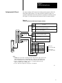
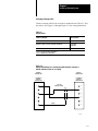
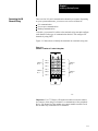
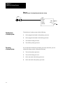
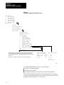
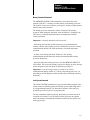
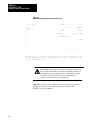
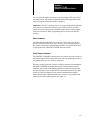
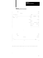
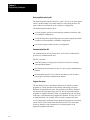
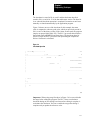
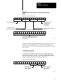
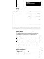
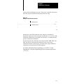
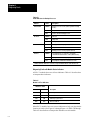
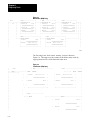
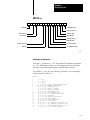
Figure 5.7
Sending a Message at Switchover
| B1:0
|
+––]
+–(EN)–+
|
00
|
|
|
|
|
|
|
|
|
|
|
|
|
S0:3
+MSG–––––––––––––––––––––––––+
[–––]
[–––––––––––––––––––––––––––––––+MESSAGE
17
|Control
|Channel
#B200:1|
E2.5.1+–(DN)
|#H045$N4:17=$B3:5
|
|
+–(ER)
|
|
|
|
+––––––––––––––––––––––––––––+
Bit B1:0/00 is an internal storage bit used to control execution of the
transfer command. You can use any unused data table bit for this purpose. Bit
S0:3/17 is the run/backup bit.
Automatic Switchover
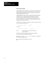
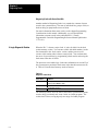
The following information applies if you selected Data Highway and
configured your PLC-3 backup system for automatic switchover.
At switchover,
the data highway port is disabled on the communication adapter module
in the primary processor
the station addresses of the Data Highway and modem ports on the
communication adapter module in the backup processor change to those
selected in LIST
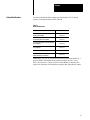
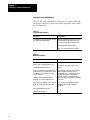
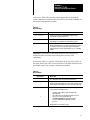
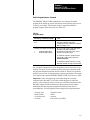
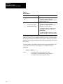
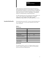
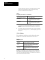
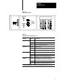
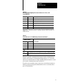
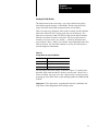
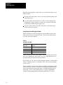
Table 5.H lists the conditional responses that can occur with automatic
switchover.
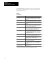
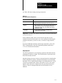
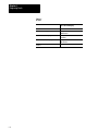
Table 5.H
Automatic Switchover Responses
Switchover occurs and:
Then:
the processor is waiting for a response
the response is ignored.
5-21