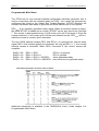
1
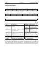
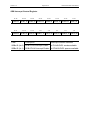
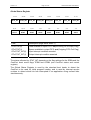
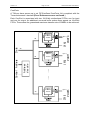
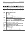
External
Interface
User Manual
User Manual (QCF42); Version 3.0, 5/2/01; © Sundance Multiprocessor Technology Ltd. 2001
Version 1.3
Page 2 of 45
External Interface User Manual
Revision History
Date
Comments
Engineer
Version
27/01/03
First version
J.V.
1.0
26/08/03
ComPort notation updated
J.V.
1.1
31/10/03
SDL section added
JPA
1.2
31/04/05
Comport interrupt condition detailed
J.V.
1.3
Version 1.3
Page 3 of 45
External Interface User Manual
Table of Contents
Revision History ....................................................................................................... 2
Contacting Sundance............................................................................................... 4
Notational Conventions ........................................................................................... 5
Register Descriptions .............................................................................................. 5
Introduction............................................................................................................... 6
Interrupts................................................................................................................... 7
Interrupt Control Register........................................................................................ 8
SDB Interrupt Control Register ............................................................................... 9
Global Status Register .......................................................................................... 10
SDB Status Register ............................................................................................. 11
Global bus status register ..................................................................................... 11
Communication ports ............................................................................................ 12
Overview ............................................................................................................... 12
ComPort Status and Control Register ................................................................... 13
ComPort Status and Control Register ................................................................... 14
Debugging flags .................................................................................................... 15
Sundance Digital Link ............................................................................................ 18
Overview ............................................................................................................... 18
SDL debugging flags............................................................................................. 20
SDB .......................................................................................................................... 21
SDB Status Register ............................................................................................. 22
Debugging flags .................................................................................................... 23
Output Flag Register ............................................................................................. 24
Input Flag Register................................................................................................ 24
SDB Interrupts ...................................................................................................... 24
DMA ...................................................................................................................... 26
SDB Initialisation................................................................................................... 27
Suspending SDB transmission.............................................................................. 27
Bus exchange ....................................................................................................... 27
Data formatting ..................................................................................................... 28
Global bus ............................................................................................................... 29
Version 1.3
Page 4 of 45
External Interface User Manual
Writing to the Global Bus ...................................................................................... 29
Reading from the Global Bus ................................................................................ 30
Programmable Wait States ................................................................................... 31
Additional feature .................................................................................................. 32
Triggering the transfer with ADC ....................................................................... 32
Address reload .................................................................................................. 32
BUSY feed-back................................................................................................ 32
Clock selection .................................................................................................. 32
STAT0 pulse...................................................................................................... 32
Global Bus access............................................................................................. 32
HOLD ................................................................................................................ 33
Global control configuration: ................................................................................. 33
Global Bus Operation Register ............................................................................. 34
Global Bus Control Register.................................................................................. 35
SMT310, SMT310Q, SMT300, SMT300Q ............................................................ 36
LED register ............................................................................................................ 37
Typical LED Register ............................................................................................ 37
CONFIG & NMI ........................................................................................................ 38
Config Register ..................................................................................................... 38
Timer........................................................................................................................ 39
Timer Control Register .......................................................................................... 39
IIOF interrupt........................................................................................................... 40
IIOF Register......................................................................................................... 40
Virtex Memory Map................................................................................................. 41
SDB Pin-Out ............................................................................................................ 43
Index ........................................................................................................................ 45
Contacting Sundance
You can contact Sundance for additional information by going onto Sundance’s
support forum http://support.sundance.com/
Version 1.3
Page 5 of 45
External Interface User Manual
Notational Conventions
Register Descriptions
The format of registers is described using diagrams of the following form:
31–24
23–16
15–8
7–0
R,00000000
R,10000000
OFLAGLEVEL
R,00000000
RW,10000000
The digits at the top of the diagram indicate bit positions within the register and the
central section names bits or bit fields. The bottom row describes what may be done
to the field and its value after reset. Shaded fields are reserved and should only ever
be written with zeroes.
R
Readable by the CPU
W
Writeable by the CPU
RW
Readable and writeable by the CPU
Binary digits indicate the value of the field after reset.
Version 1.3
Page 6 of 45
External Interface User Manual
Introduction
This document gather all the functionality of the typical Sundance’s firmware so that
the manual for each TIM can refer to it and only specify the additional features
provided.
Version 1.3
Page 7 of 45
External Interface User Manual
Interrupts
The generation of a CPU interrupt by a ComPort, an SDB, or the Global Bus starts
when the FPGA asserts an interrupt condition. For example, this may be the result of
an input FIFO becoming not empty or an output FIFO not full.
The interrupt condition is then further controlled by interrupt condition enables in the
FPGA. If enabled, an asserted interrupt condition will cause one of the CPU’s
external interrupt lines to be asserted and an interrupt event to be latched in the
processor’s Interrupt Flag Register (IFR).
Finally, the processor will be interrupted, providing the interrupt event is enabled in
the processor’s Interrupt Enable Register (IER) and the Global Interrupt Enable (GIE)
is set in the processor’s Control and Status Register (CSR).
The DSP provides four external interrupt input lines, EXT_INT4, EXT_INT5,
EXT_INT6, and EXT_INT7, which can be driven by a variety of interrupt conditions.
Each external interrupt has a separate interrupt control register (INTCTRLn) where
you set bits to enable the interrupt condition.
Version 1.3
Page 8 of 45
External Interface User Manual
Interrupt Control Register
31–30
29–28
27–26
CP0 IE CP1 IE CP2 IE
RW,00
RW,00
25–24
23–22
21–20
19–18
17–16
CP3 IE
CP4 IE
CP5 IE
SDB0 IE
SDB1 IE
RW,00
RW,00
RW,00
RW,00
RW,00
RW,00
15
14
13
12
11
10
GB IE
TCLK1 IE
TCLK0 IE
IIOF2 IE
IIOF1 IE
IIOF0 IE
RW,0
RW,0
RW,0
RW,0
RW,0
RW,0
9–0
RW,0000000000
Field
Description
Interrupt condition selected
CPx IE(bit 0)
ComPort Input FIFO Interrupt IFBM=0
Enable
IFBM=1
CPx IE (bit 1)
ComPort
Output
Interrupt Enable
FIFO OFBM=0
OFBM=1
not empty
8 words available
not full
8 spaces available
SDBx IE (bit 0)
SDB IFLAG Interrupt Enable
≥ IFLAGLEVEL words available
SDBx IE (bit 1)
SDB OFLAG Interrupt Enable
≥ OFLAGLEVEL spaces available
GB IE
Global Bus Interrupt Enable
STAT = 1
TCLKn IE
TIM clock interrupt enable
See TIM specification
IIOFn IE
External line interrupt enable
See TIM specification
It is possible to map more than one condition to an interrupt line. For example, you
might map all of the ComPort conditions to a single interrupt line and then use the
Global Status Register to find which condition or conditions had caused the interrupt.
Version 1.3
Page 9 of 45
External Interface User Manual
SDB Interrupt Control Register
31–30
29–28
27–26
25–24
23–22
21–20
19–18
17–16
SDB0 IE SDB1 IE SDB2 IE SDB3 IE SDB4 IE SDB5 IE SDB6 IE SDB7 IE
RW,00
RW,00
RW,00
RW,00
RW,00
RW,00
RW,00
RW,00
15–14
13–12
11–10
9–8
7–6
5–4
3–2
1–0
SDB8 IE SDB9 IE SDB10 IE SDB11 IE SDB12 IE SDB13 IE SDB14 IE SDB15 IE
RW,00
RW,00
RW,00
RW,00
RW,00
RW,00
RW,00
RW,00
Field
Description
Interrupt condition selected
SDBx IE (bit 0)
SDB IFLAG Interrupt Enable
≥ IFLAGLEVEL words available
SDBx IE (bit 1)
SDB OFLAG Interrupt Enable
≥ OFLAGLEVEL spaces available
Version 1.3
Page 10 of 45
External Interface User Manual
Global Status Register
31–30
29–28
27–26
25–24
23–22
21–20
19–18
17–16
CP0
STAT_INT
CP1
STAT_INT
CP2
STAT_INT
CP3
STAT_INT
CP4
STAT_INT
CP5
STAT_INT
SDB0
STAT_INT
SDB1
STAT_INT
R,10
R,10
R,10
R,10
R,10
R,10
R,10
R,10
15–14
13–12
11–10
9–8
7–6
5–4
3–2
1–0
CP0
STAT
CP1
STAT
CP2
STAT
CP3
STAT
CP4
STAT
CP5
STAT
SDB0
STAT
SDB1
STAT
R,10
R,10
R,10
R,10
R,10
R,10
R,10
R,10
Field
Description (flags active when 1)
CPx STAT(0)
Data available in input FIFO: not(Incoming FIFO Empty Flag)
CPx STAT(1)
Space available in output FIFO: not(Outgoing FIFO Full Flag)
CPx STAT_INT(0)
Input interrupt condition asserted
CPx STAT_INT(1)
Output interrupt condition asserted
The status reflected by STAT_INT depends on the flag settings for the SDBs and the
ComPort burst mode flags, IFBM and OFBM (see ComPort status and control
register).
The Global Status Register is used by the standard boot loader to detect the
ComPort to be used for initial program loading, and is used by interrupt service
routines to detect which link has interrupted in an application using several links
simultaneously.
Version 1.3
Page 11 of 45
External Interface User Manual
SDB Status Register
31–30
29–28
27–26
25–24
23–22
21–20
19–18
17–16
SDB0
STAT_INT
SDB1
STAT_INT
SDB2
STAT_INT
SDB3
STAT_INT
SDB4
STAT_INT
SDB5
STAT_INT
SDB6
STAT_INT
SDB7
STAT_INT
R,10
R,10
R,10
R,10
R,10
R,10
R,10
R,10
15–14
13–12
11–10
9–8
7–6
5–4
3–2
1–0
SDB8
STAT_INT
SDB9
STAT_INT
SDB10
STAT_INT
SDB11
STAT_INT
SDB12
STAT_INT
SDB13
STAT_INT
SDB14
STAT_INT
SDB15
STAT_INT
R,10
R,10
R,10
R,10
R,10
R,10
R,10
R,10
Field
Description (flags active when 1)
SDBx STAT_INT(0) Input interrupt condition asserted
SDBx STAT_INT(1) Output interrupt condition asserted
Global bus status register
31–16
R,00000000000000000000
15
14-13
GB INT
RW,0
RW,00
12
11
10
IIOF2 INT
IIOF1 INT
IIOF0 INT
RW,0
RW,0
RW,0
9–0
RW,0000000000
Field
Description (flags active when 1)
GB INT
Global bus interrupt condition asserted
IIOFx INT
IIOFx interrupt condition asserted
Version 1.3
Page 12 of 45
External Interface User Manual
Communication ports
Overview
According to the board you can get up to six 8-bit, data-parallel, inter-processor links
that follow Texas Instruments’ TMS320C4x Communication Port standard. Additional
information on the standard is available in the TMS320C4x User’s Guide chapter 12:
Communication ports and the Texas Instrument Module Specification.
The standard gives a TIM six links numbered from 0 to 5. Each link can be a
transmitter or a receiver, and will switch automatically between these states
depending on the way you use it. Writing to a receiver or reading from a transmitter
will cause a hardware negotiation (token exchange) that will reverse the state of both
ends of the link.
Following a processor reset, the first three links (0, 1, and 2) initialise as transmitters
and the remainder (3, 4, and 5) initialise as receivers. When you wire TIMs together
you must make sure that you only ever connect links initialising as transmitters to
links initialising as receivers; never connect two transmitters or two receivers. For
example, connecting link 0 of one TIM to link 4 of another is safe; connecting link 0 of
one TIM to link 2 of another could damage the hardware.
Always connect ComPorts 0, 1, or 2 to ComPorts 3, 4, or 5.
On most carrier board the physical connection between ComPorts is made with FMS
cables (Ref. SMT3xx-FMS). You must be careful when connecting the cables the
make sure that one end is inserted in the opposite sense to the other. One end must
have the blue backing facing out and the other must have the silver backing facing
out.
The SMT310Q (SMT320) motherboard communicates with the host PC using
ComPort 3 of the site 1 TIM. You should not make any other connections to this
ComPort.
Version 1.3
Page 13 of 45
External Interface User Manual
ComPorts
A TIM can have access up to six FIFO-buffered ComPorts, fully compliant with the
Texas Instruments’ standard [Error! Reference source not found.].
FIFO
32
D[0..7]
15x32x2
FIFO
15x32x2
Address
decode
STRB
RDY
REQ
ACK
… …
Control
Address
32
D[0..7]
PORT 1
32
FIFO
32
D[0..7]
15x32x2
STRB
RDY
REQ
ACK
PORT 5
Data
STRB
RDY
REQ
ACK
PORT 0
Each ComPort is associated with two 15x32-bit unidirectional FIFOs; one for input
and one for output. An additional one-word buffer makes them appear as 16x32-bit
FIFOs. These allow the guaranteed maximum transfer rate of 20MB/s to be achieved.
Version 1.3
Page 14 of 45
External Interface User Manual
ComPort Status and Control Register
31
30
IER
R,0
29–28
27
26
25
24
23–20
19–16
15–12
11-8
OER
IFF
IFE
OFF
OFE
IFL
OFL
R,0
R,0
R,1
R,0
R,1
R,0000
R,1111
7
6
5
4
3
2
1
0
ICPRDY
OCPRDY
CLRCP
IFBM
OFBM
CLRIF
CLROF
DIR
R,0
R,1
W,0
RW,0
RW,0
W,0
W,0
R,0
Field
DIR
Description (flags are active when 1)
0
Reading
1
Writing
CLROF
Write 1 to clear outgoing FIFO
CLRIF
Write 1 to clear incoming FIFO
OFBM
Output FIFO Burst Mode
IFBM
Input FIFO Burst Mode
CLRCP
Reset ComPort: Both FIFOs are cleared and the ComPort interface is
set back to its default direction. Use with caution (see below).
OFL
Output FIFO Level: Number of words (0–15) which can be written
OCPRDY
ComPort interface buffer OCPRDY=’1’ if empty
IFL
Incoming FIFO level: Number of words (0–15) available to be read
ICPRDY
ComPort interface buffer; ICPRDY=’0’ if empty
OFE
Outgoing FIFO Empty Flag (space is available for writing 16 words)
OFF
Outgoing FIFO Full Flag
IFE
Incoming FIFO Empty Flag
IFF
Incoming FIFO Full Flag (16 words are available to be read)
OER
Output error. The DSP has written to a full output FIFO.
IER
Input error. The DSP has read from an empty input FIFO.
0
Single-word operation
1
8-word burst mode operation
0
Single-word operation
1
8-word burst mode operation
Version 1.3
Page 15 of 45
External Interface User Manual
There is a control and status register for each of the ComPorts. There is also one
read-only Global ComPort Status Register that gathers status from all ComPorts in
one place.
Debugging flags
The bit OER has been added to show when an output error occurs. It shows that a
transfer has not been configured correctly (typically dma transfer). This flag gets set
when a write is performed to a full FIFO and data has been lost. It can be cleared by
clearing the output FIFO (using CLROF). A working application should never set this
bit.
The bit IER has been added to show when an input error occurs. It shows that a
transfer has not been configured correctly (typically dma transfer). This flag gets set
when a read is performed from an empty FIFO and invalid data has been read. It
can be cleared by clearing the input FIFO (using CLRIF). A working application
should never set this bit.
Writing
The ComPort output buffer will be loaded with the first word written by the
DSP; the next 15 writes will fill up the output FIFO. When the FIFO is full OFL
will be 0 and OFF will be 1. Any further writes from the DSP will be discarded.
Reading
The 15 first words received will fill the input FIFO; the 16th word received will
be kept in the ComPort input buffer. The DSP can read up to 16 words; any
further read will return an indeterminate value.
Reset
CLRCP should only be used in special applications where the link’s token
exchange has been disabled. This will usually be where the other end of a link
is a device—not another ComPort—that will never attempt to change the
direction of transfer. Damage to the hardware could result if both ends of the
link end up as transmitters.
Clearing the ComPort
The control and status register can be used to discard words in the FIFOs.
Writing a value with CLROF or CLRIF set will clear the selected FIFO; there is
no need to set the bit back to zero.
Note that CLRIF and CLROF clear only the FIFOs; they do not clear the oneword input or output buffers. On input you may need to set CLRIF twice. If the
FIFO is full and a word is in the input buffer, the first CLRIF will clear the FIFO
and allow a word to move in from the input buffer; the second CLRIF will
remove that word. On output you can only clear the output FIFO; any word
Version 1.3
Page 16 of 45
External Interface User Manual
already in the output buffer can only be removed by being read from the other
end of the link.
Interrupts:
The ComPort control logic can assert an interrupt condition as the result of
data being transferred. The condition indicates that either one word or a block
of 8 words has been moved. The bits IFBM and OFBM in the ComPort control
and status register select which condition will assert the interrupt line. IFBM
controls interrupt conditions for input and OFBM for output.
If IFBM=0, the condition will be asserted as soon as the input FIFO contains at
least 1 word (IFE=0). The condition will not be asserted again, even if the
FIFO contains 1 or more words until either of the following events has
occurred:
• 1 word has been read from the input FIFO; or
• A write to an interrupt control register (ICR) has set the associated
Interrupt Enable.
Following one of these events, the condition will be asserted again if or as
soon as the input FIFO contains at least 1 word.
If IFBM=1, the condition will be asserted as soon as the input FIFO contains at
least 8 words. The condition will not be asserted again, even if the FIFO
contains 8 or more words, until either of the following events has occurred:
• 8 words have been read from the input FIFO; or
• A write to an interrupt control register (ICR) has set the associated
Interrupt Enable.
Following one of these events, the condition will be asserted again if or as
soon as the input FIFO contains at least 8 words.
If OFBM=0, the condition will be asserted as soon as the output FIFO has
space for 1 or more words (OFF=0). The condition will not be asserted again,
even if the FIFO has space for 1 or more words, until either of the following
events has occurred:
• 1 word has been written to the output FIFO; or
• A write to an interrupt control register (ICR) has set the associated
Interrupt Enable.
Following one of these events, the condition will be asserted again if or as
soon as the output FIFO contains space for at least 1 word.
Version 1.3
Page 17 of 45
External Interface User Manual
If OFBM=1, the condition will be asserted as soon as the output FIFO has
space for 8 or more words. The condition will not be asserted again, even if
the FIFO has space for 8 or more words, until either of the following events
has occurred:
• 8 words have been written to the output FIFO; or
• A write to an interrupt control register (ICR) has set the associated
Interrupt Enable.
Following one of these events, the condition will be asserted again if or as
soon as the output FIFO contains space for at least 8 words.
Transfer techniques
Transfers can be managed using polling or interrupts, each with CPU control
or DMA.
Version 1.3
Page 18 of 45
External Interface User Manual
Sundance Digital Link
Overview
The SDL was developed by Sundance Multiprocessor Technology Ltd. to overcome
the speed and asynchronous transfer issues linked to a ComPort interface. It’s
compatible with TI ComPort standard.
The SDL uses the ComPort links, which provide enough lines for the data and control
signals.
According to the board you can get up to six 8-bit, data-parallel, inter-processor
Sundance Digital Links (SDL).
The SDL can work in two modes:
•
Fast mode: SDL protocol is used (not compatible with ComPort). It provides a
data rate up to 20MB/sec.
•
Slow mode: ComPort protocol is used. It provides a data rate up to 10MB/sec.
The standard gives a TIM six links numbered from 0 to 5. Each link can be a
transmitter or a receiver, and will switch automatically between these states
depending on the way you use it. Writing to a receiver or reading from a transmitter
will cause a hardware negotiation (token exchange) that will reverse the state of both
ends of the link.
Following a processor reset, the first three links (0, 1, and 2) initialise as transmitters
and the remainder (3, 4, and 5) initialise as receivers. When you wire TIMs together
you must make sure that you only ever connect links initialising as transmitters to
links initialising as receivers; never connect two transmitters or two receivers. For
example, connecting link 0 of one TIM to link 4 of another is safe; connecting link 0 of
one TIM to link 2 of another could damage the hardware.
Always connect SDL 0, 1, or 2 to SDL 3, 4, or 5.
On most carrier board the physical connection between SDL is made with FMS
cables (Ref. SMT3xx-FMS). You must be careful when connecting the cables the
make sure that one end is inserted in the opposite sense to the other. One end must
have the blue backing facing out and the other must have the silver backing facing
out.
The SMT310Q (SMT320) motherboard communicates with the host PC using
ComPort 3 of the site 1 TIM. That’s why a ComPort is implemented on this site
instead of an SDL. You should not make any other connections to this ComPort.
Version 1.3
Page 19 of 45
External Interface User Manual
SDL
A TIM can have access up to six FIFO-buffered ComPorts, fully compliant with the
Texas Instruments’ standard.
FIFO
32
D[0..7]
15x32x2
STRB
RDY
BSY REQ
ACK
REQ
32
FIFO
15x32x2
Address
decode
STRB
RDY
STRB
REQ
BSY ACK
REQ
… …
Control
Address
32
D[0..7]
PORT 1
ACK
FIFO
32
ACK
D[0..7]
15x32x2
STRB
STRB
RDY
REQ
BSYACK
REQ
ACK
PORT 5
Data
STRB
PORT 0
Each SDL is associated with two 15x32-bit unidirectional FIFOs; one for input and
one for output. An additional one-word buffer makes them appear as 16x32-bit
FIFOs. These allow the guaranteed maximum transfer rate of 20MB/s to be achieved.
Version 1.3
Page 20 of 45
External Interface User Manual
SDL Status and Control Register
See section “ComPort Status and Control Register” of “Communication Port” chapter.
Following bits have been added to ComPort Status Register:
31-30
29
28-16
15–14
13-12
12-0
-
MOD
-
-
-
-
RW,10
RW,10
0
Field
MOD
Description (flags are active when 1)
0
Slow mode: compatible with ComPort protocol
1
Fast mode: incompatible with ComPort
SDL debugging flags
See section “Debugging flags” of “Communication Port” chapter
Version 1.3
Page 21 of 45
External Interface User Manual
SDB
Some board provide Sundance Digital Buses (SDBs). These 16-bit data parallel links
for synchronous transmission can achieve high-speed data transfer across 40-way
flat ribbon cables with ground-interlaced 3.3v signals (Ref. SMT3xx-SDB-CAB).
The SDBs are connected directly to the Virtex device and can support data rates of
up to 200MB/s (100MHz). A total data rate of 400MB/s can be sustained by running
both 16-bit buses at the same time. VHDL for the SDB is available in SMT6358
packages V3.0 and above.
An SDB integrates two 256×32-bit unidirectional FIFOs, one for input and one for
output.
32
256x32x2
CLK
WEN
REQ
ACK
FIFO
32
D[0..15]
256x32x2
Control Logic
& Status
CLK
WEN
REQ
ACK
SDB B
32
Address
decode
Address Data
Control Logic
& Status
Control
D[0..15]
SDB A
FIFO
Version 1.3
Page 22 of 45
External Interface User Manual
SDB Status Register
31
30
29
IER
OER
R,0
R,0
28
IFLAG OFLAG
R,0
R,1
15–8
7
6
5
OFL
TRANS
PRI
R,11111111
RW,0
RW,0
27
26
25
24
23–16
IFF
IFE
OFF
OFE
IFL
R,0
R,1
R,0
R,1
R,00000000
4
3
2
1
0
DIS
SDBCLK
CLRIF
CLROF
DIR
RW,0
RW,0
W,0
W,0
R,0
Field
Description (flags are active when 1)
DIR
Transfer direction
CLROF
Clear outgoing FIFO
CLRIF
Clear incoming FIFO
SDBCLK
SDB clock speed
DIS
0 Reading
1 Writing
0 EMIF clock / 2 (typically 50MHz)
1 EMIF clock (typically 100MHz)
0
Pause transmission when FIFO is full
1
Continue transmission even when FIFO full
0
Transmitter wins
1
Equal priority
PRI
Priority for changing direction of transfer
TRANS
Set to 1 after reset to make this SDB start as a transmitter
OFL
Outgoing FIFO Level: number of words that can be written
IFL
Incoming FIFO Level: number of words that can be read
OFE
Outgoing FIFO Empty
OFF
Outgoing FIFO Full
IFE
Incoming FIFO Empty
IFF
Incoming FIFO Full
OFLAG
Outgoing FIFO Flag. Set when OFLAGLEVEL writes can be performed.
IFLAG
Incoming FIFO Flag. Set when IFLAGLEVEL reads can be performed.
OER
Output error. The DSP has written to a full output FIFO.
IER
Input error. The DSP has read from an empty input FIFO.
Version 1.3
Page 23 of 45
External Interface User Manual
Debugging flags
The bit OER has been added to show when an output error occurs. It shows that a
transfer has not been configured correctly (typically dma transfer). This flag gets set
when a write is performed to a full FIFO and data has been lost. It can be cleared by
clearing the output FIFO (using CLROF). A working application should never set this
bit.
The bit IER has been added to show when an input error occurs. It shows that a
transfer has not been configured correctly (typically dma transfer). This flag gets set
when a read is performed from an empty FIFO and invalid data has been read. It
can be cleared by clearing the input FIFO (using CLRIF). A working application
should never set this bit.
Version 1.3
Page 24 of 45
External Interface User Manual
Output Flag Register
31–24
23–16
15–8
7–0
RW,10000000
R,00000000
R,10000000
23–16
15–8
7–0
OTRIGGER
R,00000000
Input Flag Register
31–24
ITRIGGER
R,00000000
R,10000000
R,00000000
Field
Description
OTRIGGER
Outgoing FIFO trigger. Set to 128 after reset.
ITRIGGER
Incoming FIFO trigger. Set to 128 after reset.
RW,10000000
OFLAG in the SDB status register will be 1 when there are at least OTRIGGER
spaces available in the output FIFO. OTRIGGER must be programmed with a value
between 1 and 255.
IFLAG in the SDB status register will be 1 when there are at least ITRIGGER words
in the input FIFO. This register must be programmed with a value between 1 and
255.
CLRIF and CLROF do not affect OTRIGGER or ITRIGGER.
SDB Interrupts
The firmware has been designed to allow transfers to be controlled by interrupt
conditions. The main constraint in the design was to make sure that only one
interrupt condition could be generated for each frame of data. This cannot be done
directly by mapping the FIFO flags to interrupt lines because the flags can generate
many edges during a transfer. Instead, after generating an interrupt condition, the
FPGA prevents the device from asserting further conditions until the last access of
the frame has been performed.
Version 1.3
Page 25 of 45
External Interface User Manual
Condition assertion during output:
1. Wait until the output FIFO has enough space to store a new frame, i.e.,
spaces available in the output FIFO >= OTRIGGER.
2. Assert a condition to synchronise a frame transfer (DSP to SDB).
3. Wait until the frame transfer has been completed before looking at the
available space again. Completion is detected by observing a write to the
FIFO at address:
SDB FIFO address + 4*(OTRIGGER–1)
Condition assertion during input:
1. Wait until the input FIFO contains at least one frame, i.e., words available
in the input FIFO >= ITRIGGER.
2. Assert a condition to synchronise a frame transfer (SDB to DSP).
3. Wait until the frame transfer has completed before looking at the number of
words available again. Completion is detected by observing a read from
the FIFO being performed at address:
SDB FIFO address + 4*(ITRIGGER-1)
Writing to IFLAGLEVEL or OFLAGLEVEL will allow the corresponding condition to be
reasserted even though a complete frame transfer may not have happened.
Version 1.3
Page 26 of 45
External Interface User Manual
DMA
SDB transfers can be performed using DMA without any processor interaction.
The DMA should be set to transfer frames of up to 255 words, with read
synchronisation on the SDB’s interrupt condition. The FIFO must be addressed using
consecutive word addresses to allow for correct synchronisation; you must not use
an increment of zero on the DMA’s address into the FIFO. For transfers of more than
one frame, you must use a global index register to adjust the DMA’s address into the
FIFO as follows (note the negative frame index):
SDB OTRIGGER = FRAMESIZE
SDB ITRIGGER = FRAMESIZE
DMA Global Index = (Frame Index<<16) + Element Index
where
Element Index = 4
Frame Index = – 4*(FRAMESIZE-1)
The transfer will access words at offsets in the FIFO from 0 to FRAMESIZE-1.
Applying the negative Frame Index at the end of the frame will bring the offset back
to 0. Accessing the word at offset FRAMESIZE-1 will allow synchronisation by a new
interrupt condition.
The SDB interrupt condition must be mapped in one of the interrupt control registers
to provide synchronisation on one of the external interrupt lines. The first
synchronisation event will be generated when the interrupt control register has been
written and the condition becomes true.
Version 1.3
Page 27 of 45
External Interface User Manual
SDB Initialisation
The SDBs have been designed to allow their use with older, unidirectional SDBs.
When the processor comes out of reset, an SDB will be configured as a receiver. It
can be set to be a transmitter by the DSP, providing the other end of the bus is not
configured as a transmitter.
Initially the SDB clock is stopped; it will start running when the first transfer is
initiated. If the SDB receives 5 clock edges it will be locked as a receiver and will only
become a transmitter as the result of the normal data transfer protocols (using REQ
and ACK signals as described in the SDB specification). As long as the clock lines
are not being driven, the SDB can be switched to a transmitter by setting the TRANS
bit in its control and status register. The TRANS bit can be read to see if the bus has
been allocated. It will be set thereafter.
When connecting two SDBs together you must make one of them a transmitter
before transfers will work; this is independent of the actual direction of the first
transfer. Neither trying to switch an SDB that has already been connected to a
transmitter nor changing TRANS once the clocks have started running will have any
effect.
When two SDBs are connected it does not matter which end is set to be a
transmitter. When connecting an SDB to an input-only SDB, the SDB must be made
a transmitter.
Suspending SDB transmission
To prevent loss of data, transmission will normally be suspended when a receiving
FIFO becomes full. In certain circumstances, allowing the transmission to continue
may be more important than losing data. This can be achieved by setting the DIS bit
in the control and status register.
When DIS is set, a reading SDB will never indicate that its FIFO is full and will
continue reading; a writing SDB will ignore a full signal from the receiver and
continue to send data.
Bus exchange
The SDB allows fully bi-directional transmission but, for maximum throughput, bus
turn-around should be reduced to the minimum. The priority of bus ownership can be
selected using the PRI bit. If PRI is 1 there is no priority: a transmitter will release the
bus as soon as a receiver requests it. If PRI is 0 the transmitter will hold the bus as
long as its output FIFO contains data, even if the receiver is requesting the bus.
Version 1.3
Page 28 of 45
External Interface User Manual
Data formatting
32-bit words are sent in two 16-bit packets with the least significant bits being sent
first.
You should refer to SDB specifications V2.0 and above for technical information
[Error! Reference source not found.]. The major change since version V2.0 has
been to make the WEN signal active low. This makes it easy to connect the SDB
directly to many types of FIFO and video processors. All existing boards are
compatible with this firmware change without modification.
Version 1.3
Page 29 of 45
External Interface User Manual
Global bus
The board provides a global bus that is compatible with the TIM standard. A dual port
RAM (DPR) is used as intermediate storage for transfers of data frames between the
DSP and an external device on the global bus; each frame can have up to 256 32-bit
words. All transfers start from the first word of the DPR. For debugging, the POS field
in the Global Bus Control Register will tell you which word of the frame is being
transmitted.
When writing, the DSP writes a frame to the DPR and the FPGA then sends it across
the global bus to the external device. When reading, the FPGA reads from the
external device across the global bus to the DPR and the DSP then reads it.
The FPGA needs to know when the DSP has finished transferring data to or from the
DPR. It determines this by observing a trigger word in the DPR, usually the final word
of a frame. The FPGA hands control of the DPR to the global bus when the DSP
accesses the trigger word1. You define the trigger word by setting the Operation
Register TRIGGER field to the number of words in the frame minus one.
A Global Bus Address Register is used to hold the address to be presented to the
external device. You may elect for this address to be incremented by 1 after each
word has been moved between the DPR and the external device; you do this by
setting the INC bit in the Global Bus Control Register.
The global bus H1 clock runs at half EMIF clock speed or external close. This will be
typically a 50MHz global bus H1 clock.
Writing to the Global Bus
First specify the trigger value in the Operation Register. For example, if your frame
size were 128 words, you would write a trigger value of 127. At the same time that
you set the trigger you must also set the OPERATION bit to 1, indicating that data is
to go from the DSP to the global bus.
You may now write your data to the DPR. As soon as the FPGA detects a write to the
trigger word, it will send the data in the DPR out to the external device.
Once the complete frame has been sent, the FPGA will signal an interrupt condition
by setting the DONE flag in the Global Bus Control Register. You can use this
condition to interrupt the DSP or synchronise a DMA transfer.
1
In fact, the actual trigger condition is that bits 9–2 of the address used to access the DPR are equal
to the trigger value. The FPGA ignores bits 17–10 and bits 1–0 of the address used to access the
DPR. This means that there are many trigger locations in the address space allocated to the DPR.
Version 1.3
Page 30 of 45
External Interface User Manual
Reading from the Global Bus
First specify the trigger value in the Operation Register as described above. At the
same time that you set the trigger you must also set the OPERATION bit to 0
indicating that data is to go to the DSP from the global bus. Setting OPERATION to 0
will start a transfer of data from the external device into the DPR.
As soon as the external device has moved TRIGGER+1 words, the transfer will stop
and the FPGA will set the DONE flag in the Global Bus Control Register, signalling
an interrupt condition. You can use this condition to interrupt the DSP or synchronise
a DMA transfer.
Once DONE has been set, you may read data out of the DPR. When the FPGA
detects the DSP reading the trigger word, it will examine the AUTORESTART bit in
the Global Bus Control Register. Another frame transfer from the external device will
start if AUTORESTART is 1; no action will be taken if the bit is 0.
Version 1.3
Page 31 of 45
External Interface User Manual
Programmable Wait States
The FPGA has its own internal software-configurable wait-state generator that is
used in conjunction with the external ready line, RDY. You control the generator by
configuring two fields in the Global Bus Control Register: WTCNT specifies the
number of software wait states to generate and SWW selects one of four options.
RDYwtcnt is an internally generated ready signal. When an external access is begun,
the value WTCNT is loaded into a counter; WTCNT can be any value from 0 through
7. The counter is decremented every H1/H3 clock cycle until it becomes 0. Once the
counter reaches 0, it will remain at 0 until the next external access. RDYwtcnt will be 1
while the counter is nonzero and 0 otherwise.
The four SWW options combine RDY and RDYwtcnt to generate the internal ready
signal, RDYint that controls global bus accesses. As long as RDYint = 1, the current
external access is extended. When RDYint becomes 0, the current access will
complete.
SWW = 002
SWW = 012
SWW = 102
SWW = 112
RDYint = RDY;
RDYint = RDYwtcnt;
RDYint = RDYwtcnt OR RDY;
RDYint= RDYwtcnt AND RDY;
RDYwtcnt is ignored.
RDY is ignored.
either generates ready.
both must occur to generate ready.
Additional information is available in the TMS320C4x User’s Guide chapter 9.4:
Programmable Wait States.
Version 1.3
Page 32 of 45
External Interface User Manual
Additional feature
Triggering the transfer with ADC
The acquisition process requires two levels of synchronisation: one to show that the
data is available in the ADC which allows to perform the global bus transfer and
another one to show that the data is available in the global bus DPRAM for the DSP.
To prevent these two levels of synchronisation that would require CPU intervention
the global bus transfer can be directly initiated by the external synchronisation and
the DSP is only receiving the synchronisation showing that data is available in the
global bus DPRAM. The DMA controller can directly perform the read without any
processor interruption. The transfer is edge triggered and the trigger source is fixed.
Address reload
The global bus start address can be reloaded after each frame transfer. This is useful
when an acquisition is made from consecutive ADCs. The global bus will scan all the
ADCs in a circular fashion. A DMA controller on the C6x can then automatically
capture data from the ADCs.
BUSY feed-back
This bit is set if the global bus has not yet completed the last transfer operation. You
should wait for this bit to become zero before changing the global bus parameters:
destination address, the transfer size, and the control register. In read you should
wait for this bit to become zero before reading the data.
Clock selection
The Global bus clock source can be taken from an external source (CLKIN) instead
of being the CPU frequency/4. This enables to synchronise the global bus transfer
with an external device for synchronous transfer. This is used on the SMT310 family2
(300 / 310 / 310Q) to synchronise the board with the clock of the PCI Bridge.
STAT0 pulse
The SMT310 family requires a pulse on STAT0 during the last word of a frame
transfer. This is needed for the interface with the PCI Bridge (It is used to generate a
BLAST see bridge chip manual).
Global Bus access
The firmware has the ability to decide how the STROBE line behaves during read
and write access. It can either stay low during the full access or rise between every
single access. This setting depends on the device accessed.
Version 1.3
Page 33 of 45
External Interface User Manual
HOLD
On some motherboards the ready signal is asserted to grant the control of the global
bus but it might be necessary to have a hold time for the access to the on-board
memory after it has been granted. If this bit is set the wait state count specify a hold
time after the ready signal is asserted. This is to be used on the SMT328.
Global control configuration:
The following table gives the values to set to access the global bus resources.
SMT310Q:
Access to PCI bridge internal registers and access through aperture.
•
*GLOBAL_BUS_CTRL= PULSE| WSTRB| CLKSEL| INC;
With that setting the access through the global bus will be incremented (INC),
they will be using the carrier board clock (CLKSEL) to be synchronised with the
bridge chip. Strobe signal will stay low during write transfer (WSTRB). This will
allow the transfer to happen every clock cycle when RDY is low. At the end of the
transfer the STAT<0> signal will be asserted during the last word transfer and be
used as a BLAST signal to terminate a burst transfer to the pci bridge.
Access to SRAM
•
*GLOBAL_BUS_CTRL= CLKSEL| INC;
With that setting the access through the global bus will be incremented (INC),
they will be using the carrier board clock (CLKSEL).
SMT320:
Access to all resources
•
*GLOBAL_BUS_CTRL= INC;
With that setting the access through the global bus will be incremented (INC) and
use the on-board oscillator (EMIF clock/2: 50MHz typically).
SMT328:
Access to control register
•
*GLOBAL_BUS_CTRL= HOLD| WTCNT (2)| CLKSEL|SWW(3)| INC ;
With that setting the access through the global bus will be incremented (INC),
they will be using the carrier board clock (CLKSEL). The wait state will be waiting
for ready internal and external (SWW(3)) and hold for 2 cycles after ready is
asserted (HOLD | WTCNT (2)) .
Access to other resources (VME and DPRAM)
•
*GLOBAL_BUS_CTRL= HOLD|RSTRB|WTCNT (1)| CLKSEL|SWW(3)| INC ;
Version 1.3
Page 34 of 45
External Interface User Manual
With that setting the access through the global bus will be incremented (INC),
they will be using the carrier board clock (CLKSEL). The wait state will be waiting
for ready internal and external (SWW(3)) and hold for 1 cycles after ready is
asserted (HOLD | WTCNT (1)) .
SMT118:
Access to resources
•
*GLOBAL_BUS_CTRL= WTCNT (15) | SWW(1)| INC ;
With that setting the access through the global bus will be incremented (INC). The
wait state will be waiting for ready internal (SWW(1)). The number of wait state will
depend on the TIM accessed.
Global Bus Operation Register
31-16
15–9
NBFRAMES
8
7–0
OPERATION
TRIGGER
RW,0
RW,00000000
Field
Description
OPERATION
0
Read from the Global Bus
1
Write to the Global Bus
TRIGGER
One less than the number of words to move
NBFRAMES
Number of frames read
The latest global bus interface is double buffered for dma so that it can read ahead
the next buffer while the first one is being read by the DSP. Similarly a buffer is being
written while the previous one is being sent.
The important thing is to set the global bus operation register before enabling the
global bus interrupt on an external interrupt line so that the interrupt generated is the
one relevant to the operation (read/write).
This has changed for the SMT335 firmware as it used to need the dma event to be
forced for a write and that the external interrupt was enabled before the operation
register was set. This is the only change needed when updating from a version of the
SMT335 prior to 3.13.6.
Version 1.3
Page 35 of 45
External Interface User Manual
Global Bus Control Register
31–25
24
23
22
21
20
19–16
HOLD
PULSE
EXT_TRIGGER
RSTRB
WSTRB
WTCNT
RW,0
RW,0
RW,0
RW,0
RW,0
RW,0000
15–8
7
6
5
4-3
2
1
0
POS
RLD
CLKSEL
BUSY
SWW
INC
AUTORESTART
STAT
R,00000000
RW,0
RW,0
R,0
RW,00
W,0
RW,0
R,0
Field
Description
STAT
STAT becomes 1 when a global bus transfer has completed and
is set to 0 when the DSP next accesses the DPR.
0
The global bus read will only occur when the transfer count
is set.
1
A global bus read operation will be restarted once the DSP
has read the previous data.
0
Do not increment the address after each transfer.
1
Increment the global bus address after every access
AUTORESTART
INC
SWW
Software wait state mode selection
WTCNT
Number of software wait states (0–15)
BUSY
Set if the global bus interface has not yet completed the last
transfer operation. Cleared when the data has been written to
the external device.
CLKSEL
Select the global bus clock from external source.
(SMT310/SMT310Q Specific for PCI chip interface)
RLD
Reload start address after each frame transfer.
POS
Current position of the Global Bus transfer.
WSTRB
0
STRB rises for a cycle between writes
1
STRB stays low during the write for the frame length
0
STRB stays low during the read for the frame length
1
STRB rises for a cycle between reads
RSTRB
Version 1.3
Page 36 of 45
External Interface User Manual
EXT_TRIGGER
Start Global bus transfer on trigger. The trigger source is fixed.
The global bus can only use IIOF0 as their trigger source. The
transfer is edge triggered.
PULSE
Generate a pulse on STAT0 on the last word of the frame.
(SMT310/SMT310Q Specific for PCI chip interface)
HOLD
When set the wait state count specifies the hold time after the
bus has been granted.
SMT310, SMT310Q, SMT300, SMT300Q
Burst Transfer.
This section is not relevant for new versions of the firmware in which the hardware
handle burst interruption at page boundary.
To transfer over the PCI the global bus is set-up to be able to perform burst transfer
across the PCI bridge chip. A burst transfer is happening whenever the global bus
transfer size register is set to transfer more than one word at a time. During a burst a
word is transferred on every clock cycle.
The PC memory can be accessed through aperture 0 of the PCI Bridge but a burst
transfer must not cross a 1KBytes boundary (256 words). This is because the page
size of the bridge chip is 1KBytes.
In other words burst transfer must always be ended on a page boundary. For
example you should never burst from the pci address XXXXX3FCH to XXXXX400H.
Address XXXXX400H would actually be targeting address XXXXX000H in the pci
address space as the page accessed by this burst was in the address range
XXXXX000H - XXXXX3FCH.
To make sure a page crossing does not happen during burst access an address
alignment has to be performed. The global bus transfer size has to be reduced not to
cross a page. For DMA it is advised to align the transfer on 256 words and then setup the DMA to transfer by bursts of 256 words to ensure no page boundary is
crossed during burst.
Version 1.3
Page 37 of 45
External Interface User Manual
LED register
The number of led depends on the TIM.
Typically you will be able to find the following:
An LED always displays the state of the FPGA DONE pin. This LED is off when the
FPGA is configured (DONE=1) and on when it is not configured (DONE=0).
This LED should go on when the board is first powered up and go off when the FPGA
has been successfully programmed. If the LED does not light at power-on, check that
you have the mounting pillars and screws fitted properly. If it stays on, the DSP is not
booting correctly.
The remaining LEDs can be controlled with the LED register. Writing 1 will illuminate
the LED; writing 0 will turn it off.
Typical LED Register
31–4
3
2
1
0
LEDZ
LEDW
LEDY
LEDX
RW,0
RW,0
RW,0
RW,0
Version 1.3
Page 38 of 45
External Interface User Manual
CONFIG & NMI
The TIM specification describes the operation of an open-collector type signal
CONFIG that is driven low after reset.
This signal, on a standard C4x based TIM, is connected to the processor’s IIOF3 pin.
On the module the CONFIG signal is asserted after power on, and can be released
by writing the value (1<<6) to the config register. Conversely, CONFIG may be reasserted by writing 0 to this bit. It is not possible for software to read the state of the
CONFIG signal.
The NMI signal from the TIM connector can be routed to the DSP NMI pin.
WARNING: Several software components include code sequences that assume
setting GIE=0 in the DSP CSR will inhibit all interrupts; NMI violates that assumption.
If an NMI occurs during such code sequences it may not be safe to return from the
interrupt. This may be particularly significant if you are using the compiler’s software
pipelining facility.
Config Register
31–8
Field
TRICONF
NMIEN
7
6
NMI EN
TRI CONF
RW,0
RW,0
Description
0
drive CONFIG low
1
tri-state CONFIG
0
Disconnect NMI from the DSP
1
Connect NMI from TIM to the DSP.
5–0
Version 1.3
Page 39 of 45
External Interface User Manual
Timer
The TIM TCLK0 and TCLK1 signals can be routed to the DSP’s TOUT/TINP pins.
The signal direction must be specified, together with the routing information in the
timer control register.
Timer Control Register
31–6
Field
5
4
TCLK1 EN
TCLK9 EN
RW,0
RW,0
3–0
Description
TCLK0EN
TCLK1EN
0
TIM TCLK0 is an input
1
Enable TIM TCLK0 as an output
0
TIM TCLK1 is an input
1
Enable TIM TCLK1 as an output
If the TIM TCLKx pin is selected as an output, the DSP TOUTx signal will be used to
drive it. The TIM TCLKx pin will always drive the DSP TINPx input.
TCLK0EN
C6x
TOUT0
TCLK0
TINP0
FPGA
Version 1.3
Page 40 of 45
External Interface User Manual
IIOF interrupt
It is possible to generate pulses on the external interrupt lines of the TIM.
Writing one to an IIOF bit of the IIOF register generates a low pulse of 30 ns
minimum on the corresponding IIOF line. There is no need to clear the bit.
In read these bit can be read as one if the IIOF line is low and as zero if the IIOF line
is high. They can be used as TTL input.
On the SMT310Q:
1. It can be used for interrupting the host PC when the TIM is located on the first
site of the SMT310Q.
2. On any TIM it can give some small debugging facilities, as these lines are
available from the SMT310Q J2 header.
The SMT310 needs pull-ups added to the IIOF lines to disable them after reset.
The IACK pin functionality is not implemented.
IIOF Register
31–12
Field
IACK
10
9
8
IACK
IIOF2
IIOF1
IIOF0
W
RW
RW
RW
Description
Write
IIOFn
11
Read
Writing 1 generates a low pulse
Read as 0 when IIOFn line is high
Read as 1 when IIOFn line is low
Write
Writing 1 generates a low pulse
Read
unused
7–0
Version 1.3
Page 41 of 45
External Interface User Manual
Virtex Memory Map
A(I+5) A(i+4)
0
0
1
0
1
0
A(i+3) A(i+2) A(i+1)
0
0
0
1
Resources
0
ComPort 0 FIFO
1
ComPort 0 Status/Control
0
0
1
ComPort 1
0
1
0
ComPort 2
0
1
1
ComPort 3
1
0
0
ComPort 4
1
0
1
ComPort 5
1
1
0
1
Global Bus interrupt Status
1
1
1
0
SDB interrupt Status
1
1
1
1
Global interrupt Status
0
0
0
0
SDB 0 FIFO
0
1
SDB 0 Input Flag
1
0
SDB 0 Status/Control
1
1
SDB 0 Output Flag
0
1
SDB 1
1
0
SDB 2
1
1
SDB 3
0
0
0
Global Bus Control
0
1
Global Bus DMA Start Address
1
0
Global Bus DMA Length
1
1
A(i)
0
Global Bus Data RAM
0
0
TCLK routing register
0
1
CONFIG
1
0
LED
1
1
IIOF register
Version 1.3
1
Page 42 of 45
1
1
0
0
External Interface User Manual
0
Interrupt Control Register, INT4
1
SDB extension to INT4
0
1
Interrupt Control Register, INT5
1
0
Interrupt Control Register, INT6
1
1
Interrupt Control Register, INT7
Version 1.3
Page 43 of 45
External Interface User Manual
SDB Pin-Out
Pin
Signal
Signal
Pin
1
CLK
GND
2
3
D0
GND
4
5
D1
GND
6
7
D2
GND
8
9
D3
GND
10
11
D4
GND
12
13
D5
GND
14
15
D6
GND
16
17
D7
GND
18
19
D8
GND
20
21
D9
GND
22
23
D10
GND
24
25
D11
GND
26
27
D12
GND
28
29
D13
GND
30
31
D14
GND
32
33
D15
GND
34
35
UD0
DIR
36
37
WEN
REQ
38
39
UD1
ACK
40
Version 1.3
Page 44 of 45
External Interface User Manual
Bibliography
1. TMS320C6x Peripherals Reference Guide (literature number SPRU190) describes
common peripherals available on the digital signal processors. This book includes information on
the internal data and program memories, the external memory interface (EMIF), the host port,
multichannel-buffered serial ports, direct memory access (DMA), clocking and phase-locked loop
(PLL), and the power-down modes.
2. TIM-40 MODULE SPECIFICATION Including TMS320C44 Addendum
3. SDB Technical Specification V2.1 or above
4. TMS320C4x User's Guide (literature number SPRU063) describes the C4x 32-bit
floating-point processor, developed for digital signal processing as well as parallel processing
applications. Covered are its architecture, internal register structure, instruction set, pipeline,
specifications, and operation of its six DMA channels and six communication ports. Software and
hardware applications are included.
Version 1.3
Page 45 of 45
External Interface User Manual
Index
Bibliography....................................44
Board not working
badly-connected comports ......12, 18
comport reset misused..................15
firmware revision.............................2
LED illuminated.............................37
NMI ...............................................38
no SDB transmitter selected .........27
Comports
burst mode ....................................10
cables......................................12, 18
clearing the FIFOs ........................15
control and status registers ...........14
FIFOs ......................................13, 19
restrictions on connecting .......12, 18
warning about using reset .............15
Contacting Sundance.......................4
field values after reset......................5
Global Bus.......................................29
control register ..............................35
reading ..........................................30
writing............................................29
Input Flag Register .........................24
Interrupts...........................................7
asserting .......................................16
enabling ..........................................7
interrupt condition ...........................7
interrupt condition enable................7
mapping ..........................................8
reasserting ................................... 16
SDB interrupt condition assertion. 24
LEDs ............................................... 37
FPGA DONE pin .......................... 37
LED register ................................. 37
Links . See Comports. See Comports
NMI .............................................38, 40
waning about use ......................... 38
Notational Conventions .................. 5
Output Flag Register ..................... 24
Programmable Wait States ........... 31
register descriptions ....................... 5
SDB ................................................. 21
cables........................................... 21
initialisation................................... 27
pin-out .......................................... 43
priority .......................................... 27
status register............................... 22
suspending transmission.............. 27
using DMA.................................... 26
using DMA Global Indexes........... 26
using old-style SDBs .................... 27
VHDL ........................................... 21
WEN signal changed.................... 28
SDL and status registers .............. 20
Timer............................................... 39
timer control register .................... 39
Virtex
memory map ................................ 41