1
SMT351
User Manual
Version 1.6
Page 2 of 25
SMT351 User Manual
Revision History
Date
Comments
Engineer
Version
28/07/04
First revision
JPA
1.1
16/09/04
Added pin number for “JP1 pinout” section.
JPA
1.2
Updated connectors’ location section.
30/09/04
Updated software library section
JPA
1.3
01/06/05
Added annexe 1.
JPA
1.4
Removed Sundance logo.
18/07/06
General update for release 2 of the firmware
JPA
1.5
08/09/06
Minor changes added for the release of the JPA
firmware for the SMT351-G.
1.6
Version 1.6
Page 3 of 25
SMT351 User Manual
Table of Contents
Revision History.......................................................................................................... 2
Table of Contents ....................................................................................................... 3
Introduction................................................................................................................. 7
Description .............................................................................................................. 7
Features.................................................................................................................. 7
Additional resources ............................................................................................... 7
Architecture description .............................................................................................. 8
SMT351 block diagram ........................................................................................... 8
Block description..................................................................................................... 9
FPGA ...................................................................................................................... 9
Memory ................................................................................................................... 9
CPLD ...................................................................................................................... 9
Sundance High Speed Bus ..................................................................................... 9
Comports ................................................................................................................ 9
TTL I/Os. ............................................................................................................... 10
LEDs ..................................................................................................................... 10
JTAG..................................................................................................................... 10
Switch ................................................................................................................... 10
Using the SMT351.................................................................................................... 11
FPGA Configuration ................................................................................................. 12
Reset ........................................................................................................................ 13
Functional description............................................................................................... 14
FPGA design overview.......................................................................................... 14
Memory compartments ......................................................................................... 15
Sundance High Speed Bus (SHB) ........................................................................ 16
Registers............................................................................................................... 16
Clock structure ...................................................................................................... 17
FPGA implementation .............................................................................................. 18
Language .............................................................................................................. 18
3L Diamond........................................................................................................... 18
Synthesis and Implementation tool ....................................................................... 18
Version 1.6
Page 4 of 25
SMT351 User Manual
FPGA resource usage .......................................................................................... 18
Registers definition ................................................................................................... 19
Control register (0x4) ............................................................................................ 19
Address register Low order 16-bits (0x5) .............................................................. 19
Address register High order 16-bits (0x6) ............................................................. 19
Count register Low order 16-bits (0x7).................................................................. 19
Count register High order 16-bits (0x8) ................................................................. 20
Repeat register (0x9) ............................................................................................ 20
Application example ................................................................................................. 21
Connector Locations................................................................................................. 22
JP2 pinout................................................................................................................. 23
JP1 pinout................................................................................................................. 24
Physical Properties................................................................................................... 25
Version 1.6
Page 5 of 25
SMT351 User Manual
Table of Figures
Figure 1: SMT351 board block diagram ..................................................................... 8
Figure 2: SMT351 FPGA data flow........................................................................... 14
Figure 3: SMT351 state machine.............................................................................. 15
Figure 4: DDR SDRAM components compartments organization. ........................... 16
Figure 5: FPGA’s clock domains .............................................................................. 17
Figure 6: SMT351 connector locations ..................................................................... 22
Figure 7: TTL I/Os (JP2) pinout ................................................................................ 23
Figure 8: JTAG header (JP1) pinout......................................................................... 24
Tables of Tables
Table 1: LED description .......................................................................................... 10
Table 2: configuration comport selection. ................................................................. 12
Table 3: TIM CONFIG feature: SW1 settings ........................................................... 13
Table 4: FPGA’s clock domains description ............................................................. 17
Introduction
Description
The SMT351 card is a TIM format memory module that is able to store up to 1GB of
data at 400MB/s.
The module works in a similar way than a FIFO memory. The first data stored into
module will be available in output.
SMT351 modules can be cascaded to extend storage capability.
The module is based on DDR SDRAM memory components running at up to 133
MHz. DDR (Double Data Rate) SDRAM activates the data outputs on both the rising
and falling edges of the system clock rather than on just the rising edge, potentially
doubling the output.
A Xilinx Virtex-II Pro FPGA (or XC2VP20, or XC2VP30) controls input and output
data flows on two Sundance High-speed Bus (SHB) connectors. This bus is
compatible with a wide range of Sundance processor, converter and I/O modules
Features
2 x Sundance High-speed Bus (SHB) connectors
6 x comport connectors
Xilinx VirtexII Pro FPGA XC2VP7 (or XC2VP20, or XC2VP30)
1GB Double Data Rate (DDR) SDRAM 133 MHz
Additional resources
SUNDANCE SHB specification
TI TIM specification & user’s guide.
Samtec QSH Catalogue page
Micron DDR SDRAM webpage
Version 1.6
Page 8 of 25
SMT351 User Manual
Architecture description
SMT351 block diagram
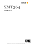
Figure 1 shows a block diagram of the SMT351 board. Refer to the following section
for additional information on the major blocks.
3 Power
Supply
LEDs
J1 Top Primary TIM
Connector
2x ComPorts/SDLs
External 5-Volt
Power Supply
converted to
2.5 Volts by a
DC-DC converter
‘FPGA configured’
LED
On-board Oscillator
50 MHz
4 LEDs + 4 TTL IOs
2 x Sundance High-speed
Bus Connectors
Xilinx FPGA
VirtexII-Pro, FF896
XC2VP7,20,30
1.5V Core
2.5/3.3V I/O
2 x RSL Connectors
(8 RSL Interfaces)
FPGA
configuration via
one of six
comports
6-pin JTAG
header
J2 Bottom Secondary TIM
Connector
4x ComPorts/SDLs
Figure 1: SMT351 board block diagram
40 I/O pins (D+@)
Clock + Feedback
128 (256) Mbytes DDR
RAM - MT46V16M16
40 I/O pins (D+@)
Clock + Feedback
128 (256) Mbytes DDR
RAM - MT46V16M16
40 I/O pins (D+@)
Clock + Feedback
128 (256) Mbytes DDR
RAM - MT46V16M16
40 I/O pins (D+@)
Clock + Feedback
128 (256) Mbytes DDR
RAM - MT46V16M16
Version 1.6
Page 9 of 25
SMT351 User Manual
Block description
This section describes the major blocks of the SMT351 board.
FPGA
The SMT351 board uses a Xilinx Virtex II Pro (XC2VP7, XC2VP20 or XC2VP30) to
control the data flow between the SMT351 board and external devices. The FPGA is
also used to implement the SHB, comport and DDR SDRAM interfaces.
The FPGA is configured via a 6-pin JTAG header or from a user-selectable Comport.
Memory
The SMT351 board contains sixteen 133 MHz DDR SDRAM components (from
Micron or Samsung) that provide up to 1 GB of storage capacity.
The DDR SDRAM is a high-speed CMOS, dynamic random-access memory.
Two versions of the SMT351 exist:
•
SMT351-M: provides 512MB storage capability;
•
SMT351-G: provides 1GB storage capability.
CPLD
A Xilinx CPLD is used to manage configuring the FPGA. It connects to the six
comports available on the module.
Sundance High Speed Bus
Two SHB connectors are available on the SMT351.
Unidirectional 32-bit SHB interfaces are implemented on SHB connectors. They run
at 100 MHz, giving a 400MB/s data rate thru the SMT351.
SHB A implements a receiver-only interface while SHB B implements a transmitteronly interface.
Please refer to the SUNDANCE SHB specification for more details.
Comports
The SMT351 provides up to 6 comports, which are used to receive the configuration
bitstream and commands to the FPGA. Once configured, the SMT351 is controlled
via comport 3.
The number of comports provided depends on the type of FPGA fitted on the board:
• XC2VP7 provides 3 comports: 0, 1 and 3.
• XC2VP20 or XC2VP30s provides 6 comports.
Version 1.6
Page 10 of 25
SMT351 User Manual
TTL I/Os.
Four TTL I/Os supporting LVTTL signals are connected directly to the FPGA (JP2).
These I/Os are not used by Sundance firmware and are available for customer use.
You must ensure that any lines you connect to these pins are LVTTL compatible in
order to protect the FPGA pads, as lines are not clamped.
See JP2 pinout section for more details.
LEDs
Five LEDs are available on the board. They are all driven by the FPGA.
Table 1: LED description
LED #
Description
D1
FPGA Done pin. The LED is on when FPAG is
NOT configured.
D2
Unused.
D3
Image of DDR SDRAM clock (board “heart
beat”).
D4
Unused.
D5
Unused.
JTAG
The SMT351 includes a 6-pin JTAG header (2mm DIL header), which allows reprogramming the FPGA using a cable such as Xilinx Parallel III or Parallel IV cables.
See connector location section for its location on board.
Refer to the following section for the pinout of this connector.
Switch
SMT351 provides two switches: SW1 and SW2.
SW1 is connected to CPLD and SW2 is connected to FPGA. SW2 is unused by the
default firmware.
Version 1.6
Page 11 of 25
SMT351 User Manual
Using the SMT351
We refer in the rest on this document to the SMT351-G. For the SMT351-M please
read 512MB instead of 1GB.
The SMT351 can store up to 1 GB of data in memory. User selects the amount of
memory to store and read back by writing in the registers of the board.
Following are described the main features that user should keep in mind when using
SMT351:
-
The SMT351 can store from 32 bytes to 1GBytes (or 512 Mbytes depending
on the type of SMT351 used). The total amount of data stored must be a
multiple of 32 bytes.
-
SMT351 will start outputting data after half of the total amount of data to store
will have been provided to it.
FPGA Configuration
There are two ways to configure the FPGA:
1. Use the on-board JTAG header and Xilinx JTAG programming tools.
2. Send the configuration bitstream down the comport selected by SW1. The
Sundance library for the SMT351 includes a function to configure the FPGA in
this way.
The table below gives the possible settings for SW1:
Table 2: configuration comport selection.
Comport
number
Switch
number 1
Switch
number 2
Switch
number 3
Switch
number 4
0
ON
ON
ON
X
1
ON
ON
OFF
X
2
ON
OFF
ON
X
3
OFF
OFF
OFF
X
4
OFF
ON
ON
X
5
OFF
ON
OFF
X
X: irrelevant
The factory setting selects comport 3 to configure the FPGA.
At power up the FPGA is not configured.
LED D1 will be lit upon FPGA configuration.
Version 1.6
Page 13 of 25
SMT351 User Manual
Reset
The SMT351 is reset by the TIM global reset.
There is also a TIM CONFIG signal provided on the TIM connector J4 pin 74. This
provides a means of reprogramming the FPGA without having to drive the TIM Global
Reset signal. CONFIG falling will reset the SMT351 in the same way that a TIM
global Reset pulse will. Other modules in the system that are sensitive to the TIM
global Reset signal will not be affected by CONFIG.
CONFIG is driven from another TIM site on the carrier board, for instance, from a
DSP module running an application. (See General Firmware Description for
information on the DSP TIM CONFIG signal).
After a Global Reset pulse, a DSP module drives CONFIG low and keeps it low by
default.
Setting SW1 switch number 2 will enable or disable TIM CONFIG:
Table 3: TIM CONFIG feature: SW1 settings
TIM CONFIG
Switch
number 4
Enabled
ON
Disabled
OFF
Once a DSP application has been loaded, CONFIG can be driven the following way:
#include “SMT3xx.h”
#define CONFIG_BIT (1<<6)
int main()
{
*CONFIG &= (UINT32)~CONFIG_BIT;
timer_delay (100);
*CONFIG |= CONFIG_BIT;
timer_delay (100);
}
Version 1.6
Page 14 of 25
SMT351 User Manual
Functional description
This section describes the functional architecture of the SMT351 programmed with
the release 2 of the firmware. This applies only to the boards shipped after the
01/08/06. The boards shipped before the 01/08/06 use the release 1 of the firmware
and you should refer to version 1.3 of the user manual. To upgrade from version 1 to
version 2 please contact Sundance.
FPGA design overview
The following diagram shows the data path implemented in the FPGA of the
SMT351:
Control
words
Com
port
Registers
Memory
compartment 0
400
MBytes/
sec
SHB
A
Mux
SHB
B
400
MBytes/
sec
Memory
compartment 1
Figure 2: SMT351 FPGA data flow.
Data input on SHB A are stored into memory and then sent to SHB B.
Memory is organised in two independent compartments: compartments 0 and
compartments 1.
Both compartments are accessed at the same time so that data can be stored in one
compartments while data are being read back from the other.
This mechanism allows a continuous data rate of 400MB/s.
This mechanism continues “repeat” times, where repeat is set by the user in the
“Repeat register”.
Version 1.6
Page 15 of 25
SMT351 User Manual
Repeat = 0
Idle
Start
command
Read
comp. 1
End of read in bankA and
end of write in bankB
Read
comp. 0
Repeat != 0
Write
comp. 0
End of write
Write
comp. 1
Figure 3: SMT351 state machine
Memory compartments
This section describes the details of the memory compartments.
The following diagram shows how the DDR SDRAM components are organized
within a memory compartment:
Page 16 of 25
SMT351 User Manual
16-bits data bus
co
m
co
m
4
po x
ne
nt
s
4
po x
ne
nt
s
16-bits data bus
32-bits data bus
Version 1.6
DDR SDRAM
32 Meg x 16 bits
DDR SDRAM
32 Meg x 16 bits
Chip Enable 3
Chip Enable 2
Chip Enable 1
Chip Enable 0
Figure 4: DDR SDRAM components compartments organization.
One compartments is made from eight 32M x 16-bits DDR SDRAM components,
each of them having a 16-bit data bus. Memory components are accessed in pairs.
Sundance High Speed Bus (SHB)
Data are input and output from SMT351 using the SHB protocol. See SUNDANCE
SHB specification for more details.
The SHB interfaces implemented in SMT351 are unidirectional full word (32-bits).
SHB A is a receiver-only interface and SHB B is a transmitter-only interface; both are
clocked at 100 MHz, giving a maximum data rate of 400 MB/s.
Registers
Command words can be sent over comport 3 to control the SMT351. Words received
will be written into registers in the FPGA. See Registers definition section for more
details.
Version 1.6
Page 17 of 25
SMT351 User Manual
Clock structure
This section describes the various clock domains in the FPGA.
The figure below shows the four clock domains of the SMT351 design and their
interrelation.
Control
words
Com
Port
Registers
Memory
compartment 0
400
MBytes/
sec
SHB
A
Input
buffer
DDR SDRAM
clock domain
Mux
Output
buffer
Memory
compartment 1
Input clock
domain
SHB
B
400
MBytes/
sec
Output clock
domain
Figure 5: FPGA’s clock domains
Table 4: FPGA’s clock domains description
Clock domain
Colour
Frequency
Description
ComPort
50 MHz
Comport and registers clock
Data input
≤ 100 MHz
SHB A clock.
Data output
100 MHz
SHB B clock.
DDR SDRAM
100 MHz
DDR SDRAM clock.
Version 1.6
Page 18 of 25
SMT351 User Manual
FPGA implementation
This section gives some technical details about the FPGA firmware.
Language
The FPGA is fully designed in VHDL.
3L Diamond
The FPGA of the SMT351 is designed with 3L Diamond FPGA.
All examples provided are designed using Diamond.
For more information about 3L Diamond please refer the 3L website.
Synthesis and Implementation tool
The design is implemented using Xilinx ISE 8.2 SP2. Synthesiser used is XST.
FPGA resource usage
Follow is the device utilization summary after Place and Route:
Resource
Number of
External IOBs
XC2VP7
70% (278/ 396)
Number of
RAMB16s
40% (18/ 44)
Number of
SLICEs
82% (4081/ 4928)
Number of
BUFGMUXs
50% (8/ 16)
Number of
DCMs
50% (2 / 4)
Power PC
0% (1 / 1)
Registers definition
The SMT351 is configured via a set of 16-bits registers described in this section.
Control register (0x4)
15-3
2
1
0
-
RST_INPUT
RDBKEN
START
-
R/W,0
R/W,0
R/W,0
Field
Description (flags are active when 1)
START
Writing ‘1’ and then ‘0’ to this bit will start the storage of the data.
RDBKEN
Read back enable. When this bit is set read back of memory is
enabled and SMT351 starts outputting data.
RST_INPUT
When this bit is set to 1, the data are cleared from the input buffer.
Address register Low order 16-bits (0x5)
Write in this register the low 16-bits of address at which you want to start the cycle.
15-0
Low order 16-bits of the address
R/W,0
Address register High order 16-bits (0x6)
Write in this register the high 16-bits of address at which you want to start the cycle.
15-0
High order 16-bits of the address
R/W,0
Count register Low order 16-bits (0x7)
Write in this register the low 16-bits of total number of 32-bits words you want to
store.
Version 1.6
Page 20 of 25
SMT351 User Manual
15-0
High order 16-bits of the word count
R/W,0
Count register High order 16-bits (0x8)
Write in this register the high 16-bits of total number of 32-bits words you want to
store.
15-0
High order 16-bits of the word count
R/W,0
Memory register 0 and memory register 1 are used to configure the SMT351 to store
different amount of data.
Repeat register (0x9)
This value stored in this register represent the number of store/read cycles the
SMT351 will execute. This is typically used when two or more SMT351 are
cascaded.
15-0
Repeat value
R/W,0
Application example
SMT351 comes with an example that illustrates the basic functions of the board.
This example is developed under 3L Diamond DSP and 3L Diamond FPGA.
version of the example using only Diamond DSP is also provided.
A
The example shows how you can configure the board to store various amounts of
data.
Connector Locations
Power
module
SHB
JTAG
RSL
Comport
select switch
Comport
configuration
CPLD
RSL
Figure 6: SMT351 connector locations
: Indicates pin 1 of connector.
VirtexII PRO
SHB
LEDs
TTL IOs
Version 1.6
Page 23 of 25
SMT351 User Manual
JP2 pinout
The following diagram shows JP2’s pinout:
JP2: TTL I/Os
1
VCC
2
TTL
0
3
TTL
1
4
TTL
2
5
TTL
3
6
GND
Figure 7: TTL I/Os (JP2) pinout
A square is drawn around pin 1 on PCB to indicate its location (Represented on
figure 5 in connectors location section).
The following table shows JP2 mapping to the FPGA:
Signal name
FPGA pin
number
TTL0
AC10
TTL1
AD10
TTL2
AC11
TTL3
AD11
Version 1.6
Page 24 of 25
SMT351 User Manual
JP1 pinout
JTAG Header
1
VCC
2
TMS
3
TCK
4
TDI
5
TDO
6
GND
Figure 8: JTAG header (JP1) pinout
Signal name
Connector pin
number
VCC
1
TMS
2
TCK
3
TDI
4
TDO
5
GND
6
A square is drawn around pin 1 on PCB to indicate its location. (Represented on
figure 5 in connectors location section).
Version 1.6
Page 25 of 25
Physical Properties
Dimensions
Weight
Supply Voltages
Supply Current
+12V
+5V
+3.3V
-5V
-12V
MTBF
SMT351 User Manual