1
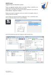
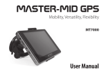
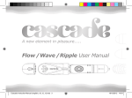
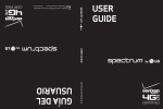
Control Software
for Program Control Tracer
Instructions
Index
1. About the Program Control Tracer・・・・・・・P.1
2. Line Tracing Mode・・・・・・・・・・・・・・・P.2
3. Programming Mode・・・・・・・・・・・・・・P.4
4. How to Use the Control Software・・・・・・P.6
5. Transferring a Control Program・・・・・・・P.7
6. Measure the Movement of the Program Control Tracer・・・P.9
7. Operate the Program Control Tracer on a course sheet・・・P.10
8. Other Functions・・・・・・・・・・・・・・・・P.11
9. Troubleshooting・・・・・・・・・・・・・・・P.12
1. About the Program Control Tracer
The program control tracer operates in two different modes.
・Programming mode
The program control tracer will follow the moves you programmed. Use the dedicated software to program
your robot.
・Line tracing mode
In line tracing mode, the program control tracer moves along a course. It uses optical sensors to detect black
course lines.
● PC requirements for the Control Software
OS : Windows XP, Vista, Windows 7
*Windows XP SP2 or higher
*Vista users will need to change the start-up settings for the Control Software.
*Your security software may delete the Control Software or prevent you from launching it.
If these things happen, please consult the security software instructions.
CPU: With specifications sufficient for smooth operation of the installed OS
Memory: With memory capacity sufficient for smooth operation of the installed OS
Recommended display: 65,000 colors or more.
800 x 600 pixels or higher resolution.
● For Window Vista users: How to change start-up settings in the Control Software
Program
Control Tracer
Open (O)
Run as Administrator (A)
Enable/Disable Digital Signature Icons
Media Info
Properties
Right-click the Control Software
icon to show the pop-up menu.
1 Select compatibility tab.
1
2 Check "Start this program in compatibility mode."
3 Check "Execute this program as an administrator."
4 Click "Apply"
2
*A user account control warning message may appear
when you start the Control Program. If this happens,
give the program permission to start.
3
4
-1-
2. Line Tracing Mode
Operate the robot in line tracing mode
Use the included "course sheet" for line tracing experiments
to verify that the tracing robot functions properly.
・How the optical sensors work
White
The optical sensors mounted on the sensor circuit measure the
Black
intensity of light reflected from the ground. The intensity
of light reflected from the black course line is different from that reflected from a white surface,
The sensor identifies the course line by detecting the difference in light intensity.
・How the Program Control Tracer works
When the right-hand sensor detects a black line, it knows that the course travels to the right. It stops the
right-hand motor, allowing the left-hand motor to turn the robot to the right.
When the left-hand sensor detects a black line, it knows that the course travels to the left. It stops the
left-hand motor, allowing the right-hand motor to turn the robot to the left.
When both sensors detect a black course line, the robot knows that the course ends and stops both motors.
・How to get a course sheet for line tracing mode
You can download a course sheet for line tracing mode from Artec's web site.
You can also create your own course.
・How to create a line tracing course
10
0m
m
Use a black marker to draw a 20mm-wide course line on a sheet of white paper. Let the program control
tracer run along the course.
The program control tracer cannot follow sharp turns or small curves with a diameter of 100 mm or less.
To prevent the robot from running astray, keep these things in mind when you make your own course.
20mm
・Example course
If you draw a circuit course, the program control tracer will keep
running. Draw a circuit course like the one in the figure to the left. Draw
a black line along the edges of the paper to catch the robot if it strays.
-2-
・How to use line tracing mode
Turn the power ON.
Place a course sheet for the line tracing mode on a flat surface. Place the
robot on the black line, matching up the center of the robot body and the
black line. (Make sure neither of the sensors lie above the black line.)
Switch on the power while one fingertip rests on the touch sensor. You will
hear a beep when the line tracing mode is activated. (Keep your fingertip
resting on the touch sensor until the beep ends.)
When you take your finger off the touch sensor, you will hear a short beep
and the tracing robot will start moving. Let's see whether the tracing robot
follows the line and stops successfully.
Touch the sensor with your
fingertip until you hear a beep.
*The touch sensor is a short-circuit switch. The circuit is completed when a finger
bridges the gap between the lead wires.
*The touch sensor may not detect dry fingertips. Moisten your fingertip with water. Be
careful not to get the circuit board wet or it may be damaged.
Place the robot on the black line, matching up the robot body and the line.
Stop position
Start
Course sheet for the line tracing mode
Troubleshooting
● The tracing robot does not move.
→ The programming mode might be activated. Turn the power OFF and ON again with a finger resting
on the touch sensor.
● The line tracing mode cannot be activated.
→ The touch sensor may not detect dry fingertips. Moisten your fingertip with water.
● The tracing robot does not follow the line.
→ In the line tracing mode, the program control tracer uses the optical sensors to detect the intensity of reflected light.
Because the sensors are susceptible to the surrounding environment, perform the experiment under constant lighting
conditions. If the room is too bright, the sensors may not work properly. Do the experiments in a room with the
ceiling light ON and the curtains closed. Make sure no part of the course sheet is shaded by anything, as this may
affect the operation of the sensors.
→ Adjust the optical sensors properly. Refer to the assembly instructions for the adjustment procedures.
-3-
3. Programming Mode
Use the software to create a program for the robot
● Instructions for installing the Control Software from the CD-ROM.
Program
Control Tracer
Insert the CD-ROM into the CD (or DVD) ROM drive of the PC. Drag & drop the icon onto the desktop.
Program
Control Tracer
Double click the icon to open it.
●Instructions for installing the Control Software from the Internet.
Visit Artec's web site (http://www.artec-kk.co.jp/pct), download the Control Software and
Program
Control Tracer
place it on the desktop. Double click the icon to open it.
Programming Icons
Program Control Tracer
File (F)
Edit (E)
Run (R)
Help (H)
Motion Commands
Basic
Data Transfer Area
Go
Advanced
Left turn
Data
Transfer
Area
Right turn
Pause
Repeat
Motion
Touch sensor
Time
Optical sensor
Order
Routine
1
Time
Optical sensor
①
②
③
1.0 Sec.
2.0 Sec.
3.0 Sec.
④
⑤
⑥
4.0 Sec.
5.0 Sec.
6.0 Sec.
⑦
⑧
⑨
7.0 Sec.
8.0 Sec.
9.0 Sec.
Subroutine 1
2
3
Both
One side
Both
One side
Left side
Left side
Right side
Right side
Sensor calibration
Subroutine 2
4
5
6
7
8
Programming Area
・Programming Screen
The figure above shows the screen you will use when creating your own control program.
To write a program, just drag & drop icons to the programming area.
You can place 24 icons on the Routine tab and 8 icons on each of the Subroutine tabs.
The tasks specified by the icons will be executed in numerical order.
You can transfer your completed program from the software to the robot via optical communication.
・Exiting the program control tracer Control Software.
Select the "File" menu. Select "Exit" to end the Control Software.
Program Control Tracer
File (F)
Edit (E) Run (R) Help (H)
Open (O)
メニュー転送位置
save as (S)
exit (X)
-4-
・Program Control Tracer: Control Software icons
Basic operation icons
Motion icons
Time-related icons
①
Go
Go
Right turn
Left turn
1.0 sec
Right turn
Left turn
⑨
Pause
Pause
9.0 sec
There are nine time
setting icons.
By default, time
periods from 1.0 to
9.0 seconds are
allocated to the
icons.
To change the time
period, double click
the time setting icon.
A time settings
pop-up menu will
appear. From here
you can set the time
period between 0.5
and 25.5 seconds, in
0.1 second
increments.
Sensor-related icons
Sensor calibration
These icons are needed to write programs that use the optical sensors.
(See "6. Programs using the optical sensors," on page six.)
The sensors use the light intensity of the starting point as a reference
value. Light intensity values the same or higher than the reference value
are considered white; values below are considered black.
Until both sensors
detect white color
Both
Until either of the
sensors detect
One side white color
Until either of the
sensors detect
One side white color
Until the right
sensor detects
Right side white color
Until the left
sensor detects
Left side white color
Until the right
sensor detects
Right side black color
Until both sensors
detect black color
Both
Until the left sensor
detects black color
Left side
Advanced operation icons
Repeat
start
Start repeating a
part of a program
from this point.
●Configure icons
Stop repeating
here.
005 times
repeat
1
Subroutine
Allows you to
insert a certain
action sequence
in your program.
2
Subroutine
Allows you to
insert a certain
action sequence
in your program.
Touch sensor
Pause the program.
Use the touch sensor
to end the pause.
You can change the set values of the time-related icons ①-⑨ and the repeat icon. Double click
the icon to show the pop-up window. Change the set value and click "OK" to change the setting.
Set the time period
The number of repeats
Using the time setting icons, you can set nine
different time periods between 0.5 and 25.5
seconds. The minimum unit is 0.1 second.
You can specify between 1 and 255 repeats.
The minimum unit is one.
-5-
4. How to Use the Control Software
Program Control Tracer
File (F)
Edit (E) Run (R) Help (H)
Data Transfer Area
Motion Commands
Time
Basic
①
Go
Advanced
Left turn
Right turn
Pause
Order
Repeat
Motion
Time
Optical sensor
Touch sensor
Routine
②
1.0 Sec.
2.0 Sec.
3.0 Sec.
④
⑤
⑥
4.0 Sec.
5.0 Sec.
6.0 Sec.
⑦
⑧
⑨
7.0 Sec.
Go
8.0 Sec.
9.0 Sec.
Subroutine 1
1
2
Optical sensor
③
Both
One side
Both
One side
Left side
Left side
Right side
Right side
Sensor calibration
Drag & Drop
②
Subroutine
2
3
4
2.0 Sec.
5
6
7
Row A
8
Row B
Go
①
Row C
1.0 Sec.
・Creating a Control Program
Drag and drop basic / advanced icons onto the Programming Area to create a program. Place repeat
icons on "Row A". Place motion icons, Subroutine 1 & 2 icons, and Touch Sensor icons on "Row B".
Let's practice creating a program. Drag & drop the "GO" icon onto the first row of the Routine. When
you place motion icons, a time setting icon will automatically appear below them on the second row. If
you want to change the default time icon, replace it with a different one.
You can edit icons placed on the Routine.
Edit menu
Delete (X)
Delete a column (Y)
Order
Repeat
Motion
Touch sensor
Time
Left turn
Go
①
②
③
④
1.0 Sec.
2.0 Sec.
3.0 Sec.
4.0 Sec.
Repeat
Right turn
Order
Go
5
Motion
4
Touch sensor
3
Time
2
Time
"Insert a column"
puts a new column in
between two existing ones.
・Useful Functions
File → Open : Opens saved data.
File → Save As:Saves created program.
-6-
Subroutine 1
1
2
Subroutine 2
3
4
Left turn
Go
③
④
1.0 Sec.
3.0 Sec.
4.0 Sec.
Subroutine 1
1
Go
2
③
④
1.0 Sec.
3.0 Sec.
4.0 Sec.
1
4
5
Go
①
Routine
Subroutine 2
3
Left turn
5
Go
①
Routine
Repeat
1
"Delete a column"
removes a column, pulling the
remaining columns to the left.
Order
Subroutine 2
Motion
Repeat
Subroutine 1
Touch sensor
Order
Motion
Time
Optical sensor
Touch sensor
Routine
Optical sensor
"Delete" removes an icon.
Routine
Optical sensor
Add a column (Z)
Optical sensor
To show the edit menu, right-click on the
icon you want to change.
Subroutine 1
2
Subroutine 2
3
4
5
Right turn
Left turn
①
②
③
④
1.0 Sec.
2.0 Sec.
3.0 Sec.
4.0 Sec.
Go
Go
・Useful Functions
Edit → Reset : Start over with a new program
Edit → Reset times: Resets all time settings to default without deleting
an existing program
Edit → Display text : Shows a readable text version of the program
you created.
● Text example
Start motion sequence
● Example Routine
Order
Repeat
Motion
Time
Optical sensor
Touch sensor
Routine
Subroutine 1
1
Basic motion
01. Repeat
02. Repeat
03. Repeat
04. Repeat
Subroutine 2
2
3
4
Go
Right turn
Subroutine
1
5
6
7
Touch sensor
Go
Left turn
8
5.0 Sec.
NO Calibrate the sensor
NO Go 5.0 S
YES Right turn 1.0 S
NO Subroutine1
Subroutine 1
Basic motion
05. Repeat start: NO Touch senser
06. Repeat start: NO Go 6.0 S
07. Repeat start: NO Left turn 4.0 S
⑤
Sensor calibration
start:
start:
start:
start:
Both
End motion sequence
5. Transferring a Control Program
How to transfer a control program
The control program you created on the PC can be transferred to the robot via optical communication.
To ensure proper data communication, keep the computer screen out of strong light. Make necessary lighting
adjustments if the robot has difficult seeing the flashing lights. It may help to cover the sensor with your hand.
Please note that the following may affect data transfer:
-Light shines through a window onto the computer screen.
-Bright lights or lamps are reflected in the computer screen.
-The computer screen has a high-gloss surface, excellent color performance, or high contrast.
Troubleshooting data transfer problems:
・ Close curtains to shut out strong light coming in through the windows.
・ Darken the room by turning the light off.
・ Angle the computer screen to your side.
・ While holding the sensor on the data transfer area with one hand, shade it with a notebook or piece of cardboard.
・ Use the included optical sensor protective cover to shut out unnecessary light.
・ Adjust the brightness and contrast of your computer screen, according to the manufacturer's directions.
(Optimal settings may vary depending on the monitor type and compatibility with the optical sensor.)
Data Transfer Area
Data Transfer Area
The optical sensor protective cover is
printed on the back of the assembly
instructions. Cut it out and place it on a
sheet of cardboard. Cut the cardboard to
match. Glue and assemble the cover.
Cardboard
-7-
Place icons on the Routine. When you complete your program,
transfer it to the program control tracer, following the procedures below.
Order
Repeat
Motion
Time
Touch sensor
Routine
Optical sensor
● Example Routine
Subroutine 1
1
2
Subroutine 2
3
4
5
Right turn
Left turn
①
②
③
④
⑤
1.0 Sec.
2.0 Sec.
3.0 Sec.
4.0 Sec.
5.0 Sec.
Go
Go
Right turn
① Remove the optical sensor from the program control tracer.
Press down the rivet collar and remove the rivet from
the back of the sensor board.
② Put the optical sensor on the data transfer area.
Make sure the sensors are right above the white circles
Data Transfer Area
in the black squares. If the sensors and the circles are
not aligned, adjust the position of the black squares
with the bar at the bottom of the Data Transfer Area.
③ From the Run menu, select the "Transfer" option.
Program Control Tracer
File (F)
Edit (E)
Run (R)
Help (H)
Transfer (T)
④ When the Data Transfer screen pops up, turn ON the program control tracer and listen for a long beep.
Make sure to keep holding the optical sensor on the Data Transfer Area.
⑤ Click "OK" on the Data Transfer screen to start the data transfer.
You will see a progress bar and
hear an occasional short beep or
chirping sound while the program
data is being transferred.
⑥ When the data transfer is completed, you will hear a long beep and the programming screen will reappear.
*You will hear no beeps or chirps if the data transfer fails.
⑦ Return the sensor board to the main body.
⑧ To execute the control program, tap the touch sensor on the main circuit board with your fingertip.
⑨ To repeat the same program, tap the touch sensor again.
⑩ When you turn the power OFF, the program data in the robot will be erased.
After you complete a successful data transfer, return the sensor board to the main body.
Tap the touch sensor to execute the program.
-8-
6. Measure the Movement of the Program Control Tracer
The motor-integrated gear boxes control the motion of the program control tracer. The performance of individual gear
boxes may vary. If the two gear boxes provide different performance, the robot may veer slightly as it travels forward.
Performance is also affected by the state of the batteries.
It is recommended that you fine tune your program for optimal performance. To determine what adjustments are
needed, create a test program with the Control Software and let the robot run on the measurement gauges*. Adjust
your program based on the measurement results.
*Please use the measurement gauges on pages 11 and 12.
Measuring straight movement
11 to
Create several control programs that make the robot move straight. Use the gauge ruler on page 11
measure the following:
-How many seconds does it take for the robot to travel a given distance?
-How far can the robot travel in a given time period?
11 to record the results.
Use the table on page 11
10
1 2 3 4 5 6 7 8 9
111213141516171819
Measuring a turn
Create several control programs that make the robot execute left or right turns. Use the protractor
12 to measure the following:
on page 12
-How many seconds does it take to turn the robot to a given target angle?
-How far can the robot turn in a given time period?
12 to record the results.
Use the table on page 12
30
10
0
10
20
30
40
60
50
40
20
50
60
80
80
70
70
90
90
Two different measurements
Measure the distance traveled in a given unit of time
Measure the time needed to travel a given distance
By performing these experiments, you will understand the capabilities of the robot.
-9-
7. Operate the Program Control Tracer on a course sheet
*Download a course sheet for the programming mode from Artec's website.
START
GOAL
B
Turn B
Turn A
GOAL
A
Turn C
Course sheet for Programming Mode
How to use the course sheet
Create a control program that makes your robot to travel from the Start, through the Turn areas, and arrive at the Goal.
Utilize the optical sensors
To create a program that uses the optical sensors, drag & drop the
icon onto the first column in row C.
Sensor calibration
● Example Routine
Order
Repeat
Motion
Touch sensor
Time
Optical sensor
Routine
1
Sensor calibration
Subroutine 1
2
3
Subroutine 2
4
5
Go
Right turn
Left turn
Go
Both
Both
Both
Both
6
7
8
Row A
⑤
Row B
Row C
④
③
When the above program is executed, the sensors will calibrate by
measuring the light intensity of the start point. They use this measurement
as a reference value. Light intensity values the same or higher than the
reference value are considered white; values below are considered black.
The larger the difference between black and white, the easier it is for the
sensor to detect the course line.
① The Sensor Calibration icon instructs the robot to calibrate the light
sensors. Once this is done, it moves to the next step in the program.
② The robot goes straight until both sensors detect black, then it proceeds
to the next step.
③ The robot keeps turning right until the right sensor detects white color,
then it proceeds to the next step.
④ The robot keeps turning left until both sensors detect black, then it
proceeds to the next step.
⑤ The robot goes straight until it detects white. The program is complete.
-10-
②
① Starting point
8. Other functions
Advanced operations
Using the Repeat function
This function allows you to repeat a portion of your control program. Bracket the desired portion between icons on Row A.
Repeat
start
Place a Repeat icon at the beginning and a icon at the end of the portion to be repeated.
005 times
repeat
Setting the number of repeats
Double click the icon to show a pop-up window.
005 times
repeat
You can specify between 1 and 255 repeats.
● Example routine - Repeat commands between the second and fifth columns.
Time
Subroutine 1
Subroutine 2
1
2
3
4
5
Go
Right turn
Left turn
Go
Right turn
6
7
8
Row A
*The repeat function is applicable to two or more commands.
Row B
Optical sensor
Motion
Touch sensor
Repeat
Order
Routine
You cannot repeat just one command.
Row C
Place a Repeat icon before the beginning and a Repeat-005 icon after the end position.
How to use the Subroutines
Use the Subroutine 1 & 2 tabs to program a list of commands to be called from the main Routine tab. Click the Subroutine 1 tab to
show its programming area. Place icons on the Subroutine in the same manner you did on the Routine. The Repeat, Subroutine, and
Touch Sensor icons are not available on the Subroutine.
When you finish placing icons on the Subroutine, go back to the Routine tab. Define where to execute the subroutine by placing the
Subroutine 1 icon on Row B. (You can create and insert a Subroutine 2 program in the same manner as the Subroutine 1.)
● Example Subroutine
Subroutine 2
Right turn
Left turn
Go
Right turn
7
8
Row A
Row B
Row C
Repeat
Go
6
Touch sensor
5
Time
4
Optical sensor
3
Order
Routine
2
Optical sensor
Time
Subroutine 1
1
Motion
Motion
Order
Routine
Subroutine 1
Subroutine 2
1
2
3
4
5
6
7
Go
Right turn
Left turn
Go
Right turn
Subroutine
1
Left turn
8
Row A
Row B
Row C
How to use the Touch Sensor icon
The Touch Sensor icon pauses the program execution. Define where to use the Touch Sensor by placing the Touch Sensor icon on Row B.
The robot pauses the program at the position you placed the Touch Sensor icon. Tap the Touch Sensor to resume program execution.
● Example Routine
Time
Repeat
Touch sensor
Motion
Optical sensor
Order
Routine
Subroutine 1
Subroutine 2
1
2
3
4
5
6
7
Go
Right turn
Left turn
Go
Touch sensor
Right turn
Left turn
8
Row A
Row B
Row C
-11-
9. Troubleshooting
093558 Program Control Tracer (soldering required)
◎ The robot does not operate properly.
・Refer back to the assembly instructions. Verify that the circuit board is
properly assembled and that the wiring is correct.
・Check all the parts with polarity (+ /-) to see if they are attached in the proper orientation.
Carefully consult the assembly instructions.
・Check whether the soldering was performed properly.
・Verify that no conductive wires are short circuited.
093558 Program Control Tracer (soldering required)
093559 Program Control Tracer
◎ The robot does not operate properly.
● The robot does not move.
・Batteries may be drained. Replace old batteries with new ones.
・Check if the robot is assembled properly, reading the assembly instructions carefully.
・Check if all wires are connected properly. Solder the conductive wires, if necessary, to complete the wiring.
● The wheels rotate in the wrong direction.
・Compare the robot to the assembly instructions. Ensure that the gear box is properly mounted.
◎ The Touch Sensor does not work.
・The Touch Sensor may not detect dry fingertips. Moisten your fingertip with water.
*Be careful not to get the circuit board wet or it may be damaged.
・The sensor may not work properly due to reduced sensitivity if batteries are drained.
Replace old batteries with new ones.
◎ You have trouble getting the robot to use the optical sensors.
・In operating these programs, the sensors measure the light intensity of the starting point and use it as a
reference value. Light intensity values the same or higher than the reference value are considered white;
values below are considered black.
・Make sure to keep the starting point bright enough. If the light intensity of the starting point is close to
that of the black course line, the sensors will have reduced sensitivity, resulting in difficulty detecting
course lines. Perform the experiment under constant lighting conditions. Make sure no part of the course
sheet is shaded by anything, as this may affect the operation of the sensors.
・Adjust the optical sensors properly. Refer to the back side of the assembly instructions for the
adjustment procedures.
・The sensor may not work properly due to reduced sensitivity if batteries are drained. Replace old
batteries with new ones.
◎ The program does not transfer.
・Adjust data transfer settings, referring to "5. Transferring a Control Program to Program Control Tracer"
on page seven of the Control Software instructions.
・The sensor may not work properly due to reduced sensitivity if batteries are drained. Replace old
batteries with new ones.
-12-
K0812