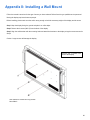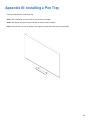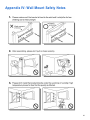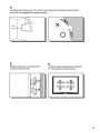
1
VTE-3200 Super-slim LED Display Model VTE-3200 Installation/Operation Manual COPYRIGHT AND TRADEMARKS: © Copyright 2015. This document contains proprietary information protected by copyright, trademark and other intellectual property laws. All rights are reserved. No part of this manual may be reproduced by any mechanical, electronic or other means, in any form, without our prior written permission. The trademarks reproduced in this document and used on the products are either owned or licensed by us, or by their respective holders. You may not reproduce or use the trademarks without our prior written consent. 2 Important Safety Instructions Thank you for your purchase of this VIVIDtouch Interactive Display. To ensure the best possible viewer experience, please read this manual carefully as it is your guide through the menus and operation. 1. Read these instructions. 2. Keep these instructions. 3. Heed all warnings. 4. Follow all instructions. 5. Do not use this apparatus near water. 6. Clean only with a dry cloth. 7. Do not block any of the ventilation openings. Install in accordance with the manufacturer’s instructions. 8. Do not install near any heat sources such as radiators, stoves, or other apparatus (including amplifiers) that produce heat. 9. Do not defeat the safety purpose of the polarised or grounding type plug. A polarised plug has two blades with one wider than the other. A grounding type plug has two blades and a third grounding prong. The wide blade or the third prong is provided for your safety. When the provided plug does not fit into your outlet, consult an electrician for the replacement of the obsolete outlet. 10. Protect the power cord from being walked on or pinched particularly at plugs, convenience receptacles and the point where they exit from the apparatus. 11. If an extension cord must be used, ensure that the voltage rating exceeds the maximum power consumption of the apparatus; otherwise, the extension cord may overheat. 12. Only use the attachments/accessories specified by the manufacturer. 13. Use only with a cart, stand, bracket specified by the manufacturer or sold with the apparatus. When a cart is used, use caution when moving the cart/ apparatus to avoid injury from tip-over. 14. Disconnect all cables form the apparatus before moving it. 15. Unplug this apparatus during lightning storms or when unused for long periods of time. 16. Refer all servicing to qualified service personnel. Servicing is required when the apparatus has been damaged in any way, such as power supply cord or plug is damaged, liquid has been spilled or objects have fallen into the apparatus, the apparatus has been exposed to rain or moisture, does not operate normally, or has been dropped. 17. Keep the packing material in case the equipment should ever need to be shipped. 3 Compliance Information DECLARATION OF CONFORMITY: VIVIDtouch hereby declares that the Product's Model Number: VTE-3200 Conforms with the provisions of: • FCC: FCC CFR Title 47 Part 15 Subpart B Class A, CISPR 22:2008 • ICES-003 Issue 5: 2012 Class A (For Canada ) • CE: EN 55022: 2010 + AC: 2011 • EN 55024: 2010 • EN 61000-3-2: 2006 + A2: 2009 • EN 61000-3-3: 2008 • cTUVus: UL 60950-1:2007 • CB: IEC 60950-1: 2005 + A1 FCC PART 15: This equipment has been tested and found to comply with the limits for a Class A digital device, pursuant to part 15 of the FCC Rules. These limits are designed to provide reasonable protection against harmful interference when the equipment is operated in a commercial environment. This equipment generates, uses, and can radiate radio frequency energy and, if not installed and used in accordance with the instruction manual, may cause harmful interference to radio communications. Operation of this equipment in a residential area is likely to cause harmful interference in which case the user will be required to correct the interference at his own expense. 4 INDUSTRY CANADA (ICES-003): CAN ICES-3 (A)/NMB-3(A) PRODUCT DISPOSAL: The Product contains small amounts of tin, lead and / or mercury. Disposal of these materials maybe regulated due to environmental considerations. DISPOSAL OF OLD ELECTRICAL AND ELECTRONIC EQUIPMENT (Applicable throughout the European Union and other European countries with separate collection programs) This symbol found on your product or on its packaging, indicates that this product should not be treated as household waste when you wish to dispose of it. Instead, it should be handed over to an applicable collection point for the recycling of electric al and electronic equipment. By ensuring this product is disposed of correctly, you will help prevent potential negative consequences to the environment and human health, which could otherwise be caused by inappropriate disposal of this product. The recycling of materials will help to conserve natural resources. This symbol is only valid in the European Union. If you wish to discard this product, please contact your local authorities or dealer and ask for the correct method of disposal. 5 Notes 6 Table of Contents Important Safety Instructions ..................................................................................................................................... 3 Compliance Inform ation ............................................................................................................................................... 4 T able of Contents ............................................................................................................................................................. 7 List of Figures ................................................................................................................................................................... 9 1. Introduction ............................................................................................................................................................... 11 About This Manual ....................................................................................................................................................................... 11 Target Audience ..........................................................................................................................................................................................11 Textual and Graphic Conventions ......................................................................................................................................................11 Using This Manual ......................................................................................................................................................................... 12 Description, Features and Benefits ......................................................................................................................................... 13 Key Features and Benefits .......................................................................................................................................................................13 Touch Capability: .........................................................................................................................................................................................13 Parts List.............................................................................................................................................................................................................13 2. Controls and Functions ........................................................................................................................................... 15 Display at a Glance ..................................................................................................................................................................... 15 Input Panel .................................................................................................................................................................................... 17 Remote Control Unit ................................................................................................................................................................... 19 3. Installation ................................................................................................................................................................. 21 Remote Control ............................................................................................................................................................................ 21 Notes on Batteries .......................................................................................................................................................................................21 Notes on Remote Control Operation .....................................................................................................................................................21 Locking and Unlocking the Remote Control & Keypad on Display ...........................................................................................21 Quick Setup ..................................................................................................................................................................................... 22 Installation Considerations ..................................................................................................................................................... 22 Ambient Light ................................................................................................................................................................................................22 Ambient Heat ...............................................................................................................................................................................................22 Ventilation ......................................................................................................................................................................................................23 Mounting the Display .................................................................................................................................................................. 24 Connections to the Display ........................................................................................................................................................ 24 Connecting a Control System or PC:......................................................................................................................................................25 IR Extender Connection: ...........................................................................................................................................................................27 Connecting Source Components to the Display ..................................................................................................................................28 Turning on the Power .................................................................................................................................................................. 30 Changing the OSD Language..................................................................................................................................................... 31 Enabling the Touch Screen ...................................................................................................................................................... 31 Connecting the Touch Screen Controller Host Computer to the Display ..................................................................................31 Software Installation ..................................................................................................................................................................................32 Touch Screen Configuration Instructions .........................................................................................................................................33 4. Op er a tion................................................................................................................................................................... 35 Using the On-Screen Menus ...................................................................................................................................................... 35 Video Settings................................................................................................................................................................................................37 Audio Settings ...............................................................................................................................................................................................42 Basic Settings ...................................................................................................................................................................................................43 Advanced Settings ......................................................................................................................................................................................45 System ..............................................................................................................................................................................................................47 7 5 . M aintenance and Troubleshooting .......................................................................................................... 48 Maintenance .................................................................................................................................................................................. 48 Troubleshooting .......................................................................................................................................................................... 48 6. External Control ....................................................................................................................................................... 50 Serial Communications ............................................................................................................................................................ 50 RS-232 Connection and Port Configuration ...................................................................................................................................50 Command and Response Format ........................................................................................................................................................50 Command and Response Examples ....................................................................................................................................................51 Serial Command List ...................................................................................................................................................................................51 Using Discrete IR Codes .............................................................................................................................................................. 57 IR Command Protocol ...............................................................................................................................................................................57 IR Control Code List ....................................................................................................................................................................................58 7. Specifications ............................................................................................................................................................. 60 Supported Timings ........................................................................................................................................................................ 61 Overall Dimensions ..................................................................................................................................................................... 62 Appendix I: Moving and Carrying Notice .............................................................................................................. 64 Moving the Display: .................................................................................................................................................................... 64 Carrying the display: .................................................................................................................................................................. 64 Appendix II: Installing a Wall Mount ...................................................................................................................... 65 Appendix III: Installing a Pen Tray ......................................................................................................................... 66 Appendix IV: Wall Mount Safety Notes .................................................................................................................. 67 8 List of Figures FIGURE 2-1. DISPLAY REAR/ SIDE VIEW ................................................................................................................................... 15 FIGURE 2-2. DISPLAY INPUT P ANEL B OTTOM V IEW ................................................................................................................. 17 FIGURE 2-3. DISPLAY R EMOTE CONTROL UNIT ........................................................................................................................ 19 FIGURE 3-1. VENTILATION REQUIREMENTS FOR ENCLOSURE MOUNTING .................................................................................... 23 FIGURE 3-2. RS-232 CONTROL SYSTEM CONNECTION ............................................................................................................. 25 FIGURE 3-3. ETHERNET CONNECTION ...................................................................................................................................... 26 FIGURE 3-4. IR EXTENDER CONNECTION ................................................................................................................................. 27 FIGURE 3-5. RECOMMENDED IR EXTENDER POSITION .............................................................................................................. 27 FIGURE 4-1. OSD MENU STRUCTURE ...................................................................................................................................... 36 FIGURE 4-2. TYPICAL PLUGE PATTERN FOR ADJUSTING BRIGHTNESS ...................................................................................... 37 FIGURE 4-3. T YPICAL G REY B AR PATTERN FOR ADJUSTING CONTRAST.................................................................................... 38 FIGURE 4-4. T YPICAL TEST PATTERN FOR ADJUSTING SHARPNESS ............................................................................................ 39 FIGURE 4-5. T YPICAL COLOUR B AR PATTERN FOR ADJUSTING COLOUR SATURATION AND HUE ................................................. 39 FIGURE 4-6. CIE 1931 CHROMATICITY D IAGRAM ........................................................................................................................ 41 FIGURE 7-1. VTE-3200 DISPLAY DIMENSIONS .......................................................................................................................... 62 9 Notes 10 1. Introduction About This Manual This Owner’s Manual describes how to install, set up and operate the VIVIDtouch Series LED Display. Throughout this manual, the VIVIDtouch Series LED Display is referred to as the “display” Target Audience The manufacturer has prepared this manual to help installers and end users get the most out of the display. The manufacturer has made every effort to ensure that this manual is accurate as of the date it was printed. However, because of ongoing product improvements and customer feedback, it may require updating from time to time. Textual and Graphic Conventions Text Conventions: The following conventions are used in this manual, in order to clarify the information and instructions provided: • Remote and built-in keypad button identifiers are set in upper-case bold type; for example, “Press EXIT to return to the previous menu.” • Computer input ( commands you type) and output (responses that appear on-screen) is shown in monospace (fixedwidth) type; for example: “To change the aspect ratio to Letterbox, type 07 00 02 41 53 50 03 08 <Enter>.” • All keys with functional names are initial-capped, set in bold type and enclosed in angle brackets. These keys are the following: <Enter>, <Spacebar>, <Control>, <Esc> and <Tab>. <Enter> indicates that you may press either the RETURN or ENTER key on your keyboard if it has both keys. • In addition to these conventions, underlining, boldface and / or italics are occasionally used to highlight important information, as in this example: NOTE A carriage return must be used after eac h command or string. 11 Graphic Conventions: These symbols appear in numerous places throughout the manual, to emphasise points that you must keep in mind to avoid problems with your equipment or injury: TIPS highlight time saving short cuts and helpful guidelines for using certain features. TIP NOTES emphasise text with unusual importance or special significance. They also provide supplemental information. NOTE CAUTION CAUTIONS alert users that a given action or omitted action can degrade performance or cause a malfunction. WARNING WARNINGS appear when a given action or omitted action can result in damage to the equipment, or possible non-fatal injury to the user. DANGER! DANGER appears when a given action can cause severe injury or death. Using This Manual Use the following table to locate the specific information you need in this manual. If you need... ... Turn to page: General information about the VIVIDtouch Series LED Display 13 Installation instructions 21 First-time configuration instructions 31 Advanced configuration instructions 45 Troubleshooting tips 48 Product specifications 60 12 Description, Features and Benefits The VIVIDtouch Series LED Display represents the cutting edge of direct-view LCD technology. They combine ultra-high resolution and unparalleled image quality with configurable I/ O in a large-format display for a wide range of digital signage and control-room applications. Key Features and Benefits The display offers these key features and benefits: • Full-HD Native Resolution: 1920 x 1080 (16:9 Native Aspect Ratio) • Ultra-wide 176-degree Viewing Angle • DisplayPort 1.1a, HDMI and DVI Inputs with High-bandwidth Digital Content Protection (HDCP), VGA, RS232, Touch USB, and LAN connections • Edge LED Backlight with active ambient light sensor to adjust backlight automatically Touch Capability: • Precise, highly-responsive touch technology • High touch sensitivity – no pressure required • Any touch: finger, gloved hand or pointer • Calibrated easily by software tools as attached • Windows 7/8 com pliant • One USB cable for easy Plug-and-Play operation Parts List Your display is shipped with the following items. If any items are missing or damaged, please contact your dealer or Customer Service. • VIVIDtouch Series LED Display • Remote Control Unit and batteries • AC Power Cord • Touch Stylus • Pen Tray • IR Extender Cable • USB Cable • VGA Cable • HDMI Cable • Quick Start Guide • USB Key – Multi-Touch Drivers & User Manual 13 Notes 14 2. Controls and Functions Display at a Glance MENU/ SOUR Figure 2-1 shows the key display components, and the paragraphs that follow describe them. Figure 2-1. Display Rear/ Side View 1. MAIN POWER SWITCH Connects or disconnects the display panel from the AC power source. 2. HANDLE Always use the handles when carrying the display. DO NOT touch or hold the screen face. 3. Status LED Solid orange: display in standby mode Blinking orange: display on, no input detected Off: main power switch off Solid green: display on, input detected 15 4. KEYPAD You can use the keypad instead of the remote control unit to operate the on-screen display (OSD) controls. The keypad operates as follows: On/Standby ( ) SOURC Press once to toggle from standby mode to on mode. Press it again to return to standby mode. SOURCE To select a source, press the SOURCE button repeatedly (with no menus visible on-screen). When a menu is visible on-screen, this button operates identically to the right-arrow (or ENTER) button on the display remote control unit. MENU/EXI When a menu is visible on-screen, this button operates identically to the left-arrow button on the display remote control unit. / When a menu is visible on-screen, these buttons operate identically to the up-and down-arrow buttons on the display remote control unit. MENU/ EXIT Press this button to access the on-screen display (OSD) controls, or to exit the current menu and return to the previous one. 16 Input Panel Figure 2-2 shows the display input panel located at the bottom of the display. Figure 2-2. Display Input Panel Bottom View 17 1. Power Input (100 to 240 VAC) Connects the display to power here. 2. Touch USB 1 A standard, Type B USB port for connecting the HDMI and VGA input sources to the display. 3. Touch USB 2 A standard, Type B USB port for connecting the DisplayPort and DVI input sources to the display. 4. RS232C In A female, 9-pin D-sub connector for interfacing with a PC or home theatre automation/control system. 5. LAN Port An RJ-45 connector for interfacing with a PC or home theater automation/control system via a Cat 5 cable. 6. DisplayPort DisplayPort 1.1a and DisplayPort-HDCP 1.1 compliant, SD/HD input for connecting SDTV, EDTV or HDTV component video sources. 7. HDMI HDCP-compliant digital video input for connecting HDMI or DVI sources. 8. DVI-D In (HDCP-compliant) VESA-standard digital video input from a personal computer, or digital video from a DVD player or HD set-top box. 9. VGA In (15-pin D-Sub) Connects components that have RGB or component output jacks, such as a personal computer or external DTV decoder (a break-out cable is needed for BNC-type connection). 10. PC Audio In Connects the audio output from a personal computer here. 11. IR Extender Connects the IR Extender cable provided with the display to this input. 12. Audio Out Connects external, powered speakers or an external audio receiver/ amplifier. 18 Remote Control Unit Figure 2-3 shows the display remote control, and Table 2-1 describes its functionality. Figure 2-3. Display Remote Control Unit 19 Table 2-1. Remote Control Button Descriptions 1 Label Description INFO Provides source and resolution information 2 3 Turns the monitor on and off VGA Selects the PC RGB source DVI Selects the PC DVI source HDMI Selects the HDMI source DISPLAYPORT Selects the DISPLAYPORT source Selects the low light setting 4 Selects standard setting Selects high brightness setting 5 BLANK Blanks the screen. Press any key to restore. 6 FREEZE Freezes the screen. Press again to restore. Opens the monitor’s on-screen menu system. 7 MENU When the menu system is already open, pressing this button will select the previous submenu Navigates through submenus and settings 8 ENTER Selects highlighted menu choices 9 EXIT Closes the menu system MUTE Turns off the sound BRIGHT Adjusts the brightness CONTRAST Adjusts the contrast AUTO Auto adjustment of VGA source SOURCE Selects each source, in sequence VOLUME - Decreases the sound volume VOLUME + Increases the sound volume 10 20 3. Installation NOTE Installation must be performed by a qualified custom video installation specialist. Remote Control To install batteries in the remote control: 1. Press down the tab on the cover and pull the cover up. 2. Insert the included batteries. Ensure that the polarities correctly match the component. 3. Insert the lower tab of the cover into the opening, and press down the cover until it clicks in place. and markings inside the battery Notes on Batteries Make sure that the battery polarities are correct when installing the batteries. • Do not mix an old battery with a new one or different types of batteries. • If you will not use the remote control for a long time, remove the batteries to avoid damage from battery leakage. • Do not expose batteries to excessive heat such as from sunshine, fire or the like. Notes on Remote Control Operation • Make sure that there is nothing obstructing the infrared beam between the remote control and the IR receiver on the display. • If the effective range of the remote control de creases, or it stops working, replace the batteries with new ones. • The remote control may fail to operate if the infrared remote sensor is exposed to bright sunlight or fluorescent lighting. • Ambient conditions may possibly impede the operation of the remote control. If this happens, point the remote control at the display, and repeat the operation. Locking and Unlocking the Remote Control & Keypad on Display You can lock the remote control buttons to prevent unauthorised persons from changing settings on the display. To do this, press ENTER, ENTER, EXIT, EXIT, ENTER and EXIT, in sequence. To unlock a locked remote control unit, use the same sequence of button presses. 21 Quick Setup Table 3-1 gives a quick overview of the display installation process. The sections following this one provide detailed instructions. Table 3-1. Installation Overview Step Procedure For Details, Refer to page... 1 Mount the display(s) on a wall (optional) 24 2 Connect other external equipment to the display (optional): Automation/control system (RS-232, Ethernet) External IR repeater 25 27 3 Connect sign al sources to the display 28 4 Apply power to the display 30 5 Change the OSD language (optional) 31 6 Perform touch screen-specific installation and configuration tasks (VIVIDtouch): Connect touch screen controller host computer to the display 31 7 Display calibration: adjust the following for each input: • Aspect ratio • Colour level • Brightness • Tint • Contrast • Input position • Colour temperature and white balance 33 Installation Considerations Proper installation of your display will ensure a satisfying viewing experience. Whether a display is installed temporarily or permanently, the following should be taken into account to ensure the best performance of the display. Ambient Light In general, minimise or eliminate light sources directed at the screen. Contrast ratio in your images will be noticeably reduced if light directly strikes the screen, such as when a shaft of light from a window or floodlight falls on the image. Images may then appear washed out and less vibrant. Direct sunlight may affect touch operation. Ambient Heat Keep the ambient temperature constant and below 35°C (95°F). Keep the display away from heating and / or air conditioning vents. 22 Ventilation If you are mounting the display in an enclosure, leave sufficient space on all sides between it and surrounding objects, as shown in Figure 3-1. This allows heat to disperse, maintaining the proper operating temperature. 50 mm (2") Wall 50 mm (2") 50 mm (2") 50 mm (2") Wall 50 mm (2") Figure 3-1. Ventilation Requirements for Enclosure Mounting 23 Mounting the Display You can mount the display on a wall. If you do decide to wall-mount the display, ensure that the wall-mount bracket is installed according to the instructions included with it. The wall must be capable of supporting a redundant weight factor three (3) times the weight of the display, or be reinforced. We recommend that this be done by a custom installation specialist. NOTE Use only the approved wall-mount kit designed for your display. Connections to the Display Proceed as follows to connect the display to your video sources, external controller(s) – if present – and AC power. When connecting your equipment: • Turn off all equipment before making any connections. • Use the correct signal cables for each source. • For best performance and to minimise cable clutter, use high-quality cables that are only as long as necessary to connect two devices. (Don't use a 7m cable when a 1.8m cable will suffice.) • Ensure that the cables are securely connected. Tighten the thumbscrews on connectors that have them. 24 Connecting a Control System or PC: RS232 Connection Use a straight-through RS-232 cable with a 9-pin male connector to connect a PC or control/ automation system (if present) to the RS-232 port on the display; see Figure 3-2. For more information about using this connection, refer to External Control on page 39. 5 4 9 3 8 1 2 7 6 2 Receive Data (to control system) 3 Transit Data (from control system) 5 Ground to Automation/ Control System or PC Figure 3-2. RS-232 Control System Connection 25 Ethernet Connection Use a standard Ethernet cable with an RJ-45 male connector to connect a PC or control/automation system (if present) to the Ethernet port on the display. For more information about using this connection, refer to External Control on page 39. Figure 3-3. Ethernet Connection 26 IR Extender Connection: Connect the provided IR extender cable to the IR Extender input as shown in Figure 3-4. Remote Control (3.5-mm, mini phono plug) Figure 3-4. IR Extender Connection Recommended IR Extender Positions for Cascading 32" Displays In controlled testing, the IR range is approximately 1.5 metres directly on-axis, and about 1 metre at plus or minus 15 degrees off-axis using the IR extender. Best performance is obtained in either position P1 or position P2. Figure 3-5. Recommended IR Extender Position 27 Connecting Source Components to the Display Connect your video sources to the display as shown and described in the sections that follow. DisplayPort Source Connection: See Figure 3-6. Figure 3-6. DisplayPort Source Connection 28 HDMI and DVI-D Source Connections: See Figure 3-7. TIP NOTE Use the HDMI inputs whenever possible. This ensures the highest video quality because the signal is carried in the digital domain throughout the entire signal path, from source component output into the display. You can also connect computers with DVI output to these inputs. Refer to Supported Timings on page 51 for a list of compatible input signals. This display supports the VESA Display Data Channel (DDC) standard. This standard provides “Plug and Play” capability; the display and a VESA DDC-compatible computer communicate their setting requirements, allowing for quick and easy setup. In order for Plug and Play to work correctly, you must turn on the display before you turn on the connected computer. HDMI or DVI-to-HDMI Cable (sold separately) BD/HD-DVD/ DVD/DTV STB DVI-D Cable (sold separately) Audio Cable (Sold Separately) Rear of the PC Figure 3-7. HDMI and DVI-D Source Connections 29 VGA Source Connection: Connect a personal computer or other RGB source to the VGA input as shown in Figure 3-8. NOTE Refer to Supported Timings on page 51 for a list of compatible input signals. D-Sub 15-pin Cable Audio Cable (Sold Separately) Rear of the PC Figure 3-8. VGA Source Connections Turning on the Power 1. Turn on your source components. 2. Plug the female end of the supplied power cord into the AC receptacle on the side of the display (AC 100V ~ 240V). See Figure 2-2. 3. Connect the other end to your AC power source. 4. Turn on the main power switch at the side of the display (see Figure 2-1). The power indicator lights orange to indicate that the display is in “standby” mode. 5. Press the power button ( the keypad. 6. After a brief warm-up period, the display will display an image. ) on the remote control to turn on the display or press the power button ( ) on 30 Changing the OSD Language The display OSD language is initially set to English, but can also display the menus in different languages. To change the OSD language: 1. Press MENU. 2. Select Basic Settings from the Main Menu. 3. Select OSD Language from the Basic Settings Menu. 4. Press or to select the desired language and press ENTER. The change takes effect immediately. Enabling the Touch Screen Before setting up your display to support touch screen capability, ensure that: • The touch screen controller host computer is turned off. • The display is turned on. • The video output from the computer is connected to a video input on the display. See Figure 3-6, Figure 3-7 or Figure 3-8. Connecting the Touch Screen Controller Host Computer to the Display Use the provided USB c able to connect the touch screen controller host computer to the USB input as shown in Figure 3-9. USB Type “B” Plug USB Type “A” Plug to PC or USB Hub Figure 3-9. Touch Screen Controller (USB) Connection After (and only after) making this connection, turn on your host computer. 31 Software Installation 1. Double-click the installation file mt_driver_kit [xxxxxx].exe, located on the USB-Key provided with the display. 2. The Touch Screen Driver Setup Wizard appears. Click Next, then click Install to start the process. 3. Click Finish to complete the installation. 32 Touch Screen Configuration Instructions Touchscreen Information: This area of the mt_touch_driver configuration window contains a variety of information about the touch module, the product type, firmware version and operating status. • Serial Number: Unique ID of a touchscreen. • Firmware Version: Internal firmware version of a touchscreen. • Touch Points: Maximum touch points that a physical touch screen supports. • Status: Show current status of a touch screen. It may be: a. Working normal b. Open bulk device failed c. Open virtual digitizer failed d. Open physic digitizer failed Calibration: If touching the screen does not place the cursor in the desired position, you may be able to correct this by performing a touch screen engine calibration. To do this: • Click Calibration. A white cross at a black background appears on the screen. • Click the white cross by hand more than 1 second and follow the cross moving to finish the four-point touch calibration. 33 Utility: Please do not execute this function, for it is for service engineer to diagnose the touch function. CAUTION This action is not reversible. 34 4. Operation Using the On-Screen Menus To display the on-screen menus, press MENU on the remote control (Figure 2-3) or built-in keypad (Figure 2-1). To select a sub-menu, use the and To select a menu item, use the ENTER. buttons to highlight it. Then, press and to enter that sub-menu. buttons to highlight it. Then, press or to adjust that setting and press The OSD menus are arranged hierarchically, as shown in Figure 4-1. Depending on the selected input source and signal characteristics, some menu options may not be available. Scheme (Video Mode) Video Settings Brightness Contrast Sharpness (Video Mode) Saturation (Video Mode) Hue Backlight Colour Temperature & Gamma Audio Settings Basic Settings Aspect Ratio Auto Scan Select Source Volume Bass Treble Balance HDMI Audio Input DP Audio Input Internal Speakers OSD Transparent OSD Location OSD Rotation OSD Language OSD Timeout Power LED User, Vivid, Cinema, Game or Sport 0, 1, 2 ... 50 ... 99, 100 0, 1, 2 ... 6, 7, 8 0, 1, 2 ... 50 ... 99, 100 0, 1, 2 ... 80 ... 99, 100 Gamma Colour Temperature Red / Green / Blue Gain Red / Green / Blue Offset Full Screen, Pillarbox or Auto On or Off VGA, HDMI, DVI, or DisplayPort 0, 1, 2 ... 50 ... 99, 100 -6, -5, -4 ... 0 ... 5, 6 HDMI or PC Audio DisplayPort or PC Audio Off or On 0, 1, 2 ... 6.... 12 Up, Down, Left, Right Landscape or Portrait English, German, Dutch, French, Danish, Slovenian, Hungarian, Serbo-Croatian 5, 10, 15 ... 30 ... 115, 120 seconds On or Off Current Date and Time Timer Mode Real Time Clock Start Up Logo Off or 2.2 5000K, 6500K, 7500K, 9300K or User 128, 129, 130 .. 256 ... 382, 383 -50, -49, -48 ... 0 ... 48, 49, 50 Power-On Power-Off On or Off User, All Days (Monday ... Sunday) or Work Days (Monday ... Friday, Saturday and Sunda y) Disable or Enable 35 Advanced Settings Auto Adjustment (Video Mode) Image Position (Video Mode) Phase (Video Mode) Clock (Video Mode) IRFM Baud Rate Smart Light Control Wake Up from Sleep Ethernet Setup System Factory Reset Channel Information Off or On Up, Dow n, Left, Right -50, ... 0, ...50 0, 1, 2 ... 63 0, 1, 2 ... 100 Off or On 115200, 38400, 19200 or 9600 Off, DCR or Light Sensor VGA Only, VGA, Digital, RS232 or Never Sleep Enable network Dynamic IP Static IP Subnet Mask Gateway DNS Address Save Network Settings Refresh Power Status Alert Source Status Alert Signal Status Alert Load Default Device MAC Yes or No Main No or Yes Disable or Enable 255.255.255.255 (0.0.0.0) 255.255.255.255 (0.0.0.0) 255.255.255.255 (0.0.0.0) 255.255.255.255 (0.0.0.0) No or Yes Refreshes dynamic IP information No or Yes No or Yes No or Yes Loads default network settings Displays MAC information Active Source / Signal Resolution and Refresh Rate Firmware Version NOTE Default settings appear in bold type. Figure 4-1. OSD Menu Structure 36 Video Settings Use the controls in the Video Settings Menu to calibrate each display input to achieve optimum picture quality. Connect your test pattern source to the input Perform the adjustments in the order listed here. that you are calibrating and proceed as follows. Scheme: Select Scheme from the Video Settings menu, then press or to select one of four image quality presets (Vivid, Cinema, Game or Sport) depending on the type of program material you are viewing. These presets automatically adjust the other image settings for optimal image quality. Or, select User to adjust Brightness, Contrast and other settings manually. Brightness: On your external test pattern source, select a PLUGE pattern. (PLUGE is an acronym for “Picture Line-Up Generation Equipment.”) Figure 4-2 shows a typical PLUGE pattern. Below Black Above Black Figure 4-2. Typical PLUGE Pattern for Adjusting Brightness PLUGE patterns vary but generally consist of some combination of black, white and grey areas against a black background. The example above includes two vertical bars and four shaded boxes. 37 Select Brightness from the Video Settings menu and press or • The darkest black bars disappear into the background. • The dark grey areas are barely visible. • The lighter grey areas are clearly visible. • The white areas are a comfortable level of true white. • The image contains only black, grey and white (no colour). to adjust the brightness so that: Contrast: On your external test pattern source, select a stepped, grey-bar pattern like the one shown in Figure 4-3. Figure 4-3. Typical Grey Bar Pattern for Adjusting Contrast Select Contrast and press in size. NOTE or to adjust the contrast to a point just below which the white rectangle starts to increase Brightness and contrast controls are interactive. A change to one may require a subtle change to the other in order to achieve the optimum setting. 38 Sharpness: “Sharpness” is the amount of high-frequency detail in the image. To adjust sharpness, select Sharpness from the Video Settings menu. On your external test pattern source, select a pattern like the one shown in Figure 4-4. Adjust as needed, looking for white edges around the transitions from black to grey and differently-sized lines in the “sweep” patterns at the top and bottom. Lower the sharpness setting to eliminate them. Figure 4-4. Typical Test Pattern for Adjusting Sharpness blue red magenta green cyan yellow grey Saturation: On your external test pattern source, select a colour bar pattern like the one shown in Figure 4-5. Figure 4-5. Typical Colour Bar Pattern for Adjusting Colour Saturation and Hue 39 Press MENU on the remote control or keypad . Select Saturation from the Video Settings menu. blue red magenta green cyan yellow grey While looking at the colour bar pattern through a blue filter, adjust the colour saturation level until the outermost (grey and blue) colour bars appear to be a single shade of blue: Hue: “Hue” (or “tint”) is essentially the ratio of red to green in the colour portion of the image. When hue is decreased, the image appears redder; when it is increased the image appears greener. To adjust the hue, use a blue filter when viewing the colour bar pattern, as you would for adjusting colour saturation (refer to the previous section, Saturation). Select Hue from the Video Settings menu and press or side of the green bar) appear to be a single shade of blue. NOTE to adjust it until the cyan and magenta colour bars (on either Like the brightness and contrast controls, the colour and tint controls are interactive. A change to one may require a subtle change to the other in order to achieve the optimum setting. Backlight: The Backlight control changes the apparent brightness of the displayed image. Its effect is similar to that of a lamp intensity control on a projector. Gamma: Select Gamma from the Video Settings menu and choose either 2.2 (default) or Off. 40 Colour Temperature: Select Colour Temperature from the Video Settings menu to adjust the colour temperature. Colour temperature establishes the “colour of grey” by adjusting the 75% white point to various colour points. • What are “colour points?” A “colour point” is an x/ y coordinate pair that defines a colour’s location on the standard CIE chromaticity graph, shown in Figure 4-6. (CIE stands for “Commission Internationale de l’Éclairage” (International Commission on Illumination), the organisation responsible for colour measurement and management standards.) 1.0 0.9 0.8 0.7 Green 0.6 Yellow 10000 8000 6667 5714 5000 D93 0.3 0.2 2222 2500 3333 4000 D50 D65 2000 Cy n 0.4 2857 0.5 Red Magenta 0.1 Blue 0.0 0.0 0.1 0.2 0.3 0.4 0.5 0.6 0.7 0.8 0.9 x 1.0 Figure 4-6. CIE 1931 Chromaticity Diagram Select a value of from 3200K to 9600K. Higher settings produce a “bluer” picture; lower ones impart a reddish hue to the image. To select a custom colour temperature, select User and set the Gain and Offset as described below. • Gain: Use the Gain controls to correct colour imbalances in the bright areas of the image. A good way to do this is to use a test pattern consisting mostly of solid white areas, such as an 80 IRE “ window ” pattern. If the white areas contain traces of red, green or blue, decrease the Gain for that colour. • Offset: Use the Offset controls to correct colour imbalances in the dark areas of the image. A good way to do this is to use a test pattern consisting mostly of dark grey areas, such as a 30 IRE “ window ” pattern. If the grey areas contain traces of red, green or blue, decrease the Offset for that colour. Aspect Ratio: To change the aspect ratio (size and shape) of the displayed image, select Aspect Ratio from the Video Settings menu and press ENTER. Select the appropriate aspect ratio for the type of program material being viewed. Note that some aspect ratios are unavailable and / or not useful with certain types of source material. The optimal setting depends on a number of factors, such as: • The aspect ratio of the source material, as broadcast or encoded on the playback medium. • The “display type” (16:9 or 4:3) and output resolution settings at the source component. Most modern DVD/BD players and set-top boxes have such controls. • Viewer preference (original aspect ratio with “black bars,” or a full-screen presentation with some distortion or cropping). 41 Auto Scan: Select Auto Scan from the Video Settings menu and press or to turn this feature on or off. When set to On, Auto Scan causes the input select function (using the SOURCE button on the remote control unit or keypad ) to skip over unused inputs, saving time. Select Source: Choose Select Source from the Video Settings menu and press or to select the video source. Audio Settings Volume: Select Volume from the Audio Settings menu and press or Bass: Select Bass from the Audio Settings menu and press to cut or boost the low audio frequencies. Treble: Select Treble from the Audio Settings menu and press or or to change the audio volume. to cut or boost the high audio frequencies. Balance: To adjust the left/right speaker balance, select Balance from the Audio Settings menu and press make one channel louder than the other. or to HDMI Audio Input: If you are using one of the HDMI inputs with a PC or other device that does not support audio output via HDMI, set HDMI Audio Input to PC for that input. (Also connect the audio output from your source as shown in Figure 3-5.) This setting associates the PC Audio In input with that HDMI input. DP Audio Input: If you are using the DisplayPort input with a PC or other device that does not support audio output via DisplayPort, set DP Audio Input to PC for that input. (Also connect the audio output from your source as shown in Figure 3-5.) This setting associates the PC Audio In input with the DisplayPort input. Internal Speakers: Set Internal Speakers to Off to disable the internal speakers on the display. Set it to On to enable them. 42 Basic Settings OSD Transparent: Select OSD Transparent from the Basic Settings menu and press or to adjust the degree of translucence (show-through) in the menus and message boxes. Zero (0) means that the menus are opaque. OSD Location: Select OSD Location from the Basic Settings menu and press desired location. or to move the OSD menu to the OSD Rotation: Select OSD Rotation from the Basic Settings menu and press OSD menu to match that of the display. or to change the orientation of the OSD Language: Select OSD Language from the Basic Settings menu and press or to select the OSD Language. OSD Timeout: Select OSD Timeout from the Basic Settings menu to specify how long the menus remain on-screen after selecting them. Select from 5 to 120 seconds, in five-second increments. Power LED: Select Power LED from the Basic Settings menu to change the behaviour of the status indicator LED (see Figure 2-1) during standby mode. When set to On, the LED lights orange to indicate that the display is in standby mode. When set to Off, the LED is always off, regardless of the operational state of the display. Real Time Clock: Select Real Time Clock from the Basic Settings menu to set the display’s internal real-time clock. 43 From this menu, you can also program the display to turn on and off at specified times of day and days of the week: • To set power-on and power-off times for each day of the week independently, set the Timer Mode to User. • To set the same power-on and power-off times for every day of the week, set the Timer Mode to All Days. • To set the same power-on and power-off times for Monday through Friday, set the Timer Mode to Work Days. 44 Advanced Settings Auto Adjustment: Select Auto Adjustment from the Advanced Settings menu to force the display to reacquire and lock to the input signal. This is useful when the signal quality is marginal. Image Position (VGA sources): Use the controls in the Image Position (VGA sources) Menu to fine-tune the image position. • Left/Right: Select Left/Right from the Input Position menu to shift the projected image horizontally. Press the image to the right; press to shift it to the left. • Up/Down: Select Up / Down from the Input Position menu to shift the projected image vertically. to shift Phase (VGA sources): This control adjusts the phase of the pixel sampling clock relative to the incoming signal. Adjust the phase when an image still shows shimmer or “noise” after the Clock setting has been optimised. TIP Adjust the Phase after adjusting Clock (see below). For best results, use a good test pattern such as a smooth grey consisting of a clear pattern of black and white pixels, or a similar “half on, half off” graphic image. Adjust the slidebar until the image stabilises and each pixel is clearly defined. You may notice that you can stabilise the image at more than one point. Use either setting in such cases. Clock (VGA sources): This control sets the frequency of the pixel sampling clock, indicated by the number of incoming pixels per line, so that all pixels generated by a particular source are sampled. Steady flickering or several soft vertical stripes or bands across the entire image indicates poor pixel tracking. Proper pixel tracking helps ensure that the image quality is consistent across the screen, that aspect ratio is maintained and that pixel phase (see above) can be optimised. IRFM: Select IRFM from the Advanced Settings menu and press slight frame motion to help avoid image retention. or to enable or disable this feature, which creates Baud Rate: Select Baud Rate from the Advanced Settings menu and press communication link. or to set the data rate of the RS-232 45 Smart Light Control: Select Smart Light Control from the Advanced Settings menu and press or to configure the automatic backlight control feature of the display. Select one of the following, or select Off to control the backlight level manually with the Backlight control in the Video Settings menu. • Light Sensor: With this setting, the backlight level is controlled by the display’s internal ambient light sensor. • DCR: With this setting, the display automatically adjusts the backlight level according to the amount of contrast and brightness in the source material. • Wake Up From Sleep: Select Wake Up From Sleep from the Advanced Settings menu and press this feature, which operates as follows: to control VGA Only: The display normally wakes up from power-saving mode when it receives an active video signal on its VGA (analog) input. VGA, Digital, RS232: The display wakes up when it receives an active signal from its VGA, HDMI, DisplayPort or DVI inputs, or receives a valid RS-232 command. Never Sleep: The display never enters power-saving mode. Ethernet Setup: Select Ethernet Setup from the Advanced Settings menu and press settings. • or to configure the display’s network Enable Network: Enables the network feature. Option: No, Yes. • IP Address Settings: When network feature is enabled, press to configure the following IP addresses: Dynamic IP: Enable DHCP for dynamic IP address assignment. Static IP Address: Sets the static IP address when the DYNAMIC IP line is disabled or views it when the DYNAMIC IP line is enabled. Range: 255.255.255.255 (0.0.0.0) Subnet Mask: Sets the subnet mask when the DYNAMIC IP line is disabled or views it when the DYNAMIC IP line is enabled. Range: 255.255.255.255 (0.0.0.0) Gateway: Sets the gateway address when the DYNAMIC IP line is disabled or views it when the DYNAMIC IP line is enabled. Range: 255.255.255.255 (0.0.0.0) DNS Address: Sets the DNS address when the DYNAMIC IP line is disabled or views it when the DYNAMIC IP line is enabled. Range: 255.255.255.255 (0.0.0.0) Save Network Settings: Saves the network configuration when the DYNAMIC IP line is disabled. Options: No, Yes. Refresh: Refreshes the configuraiton of Static IP Address, Subnet Mask, Gateway and DNS Address. • Power Status Alert: sent when the unit is turned on or off. • Source Status Alert: sent when a different source is selected. • Signal Lost Alert: sent when the input sync is lost. • Load Default: loads default network settings. Options: No, Yes 46 • Device MAC: Shows the unique address assigned to network interfaces. Factory Reset: To reset ALL display settings (including image settings) back to their factory defaults, choose Factory Reset from the Advanced Settings menu. A confirmation message appears. Select Yes to continue with the reset or select No to cancel. CAUTION This action is not reversible. Proceed with caution! System The read -only System menu provides the following status information about the display: • The resolution and refresh rate of the active source; and • The currently-installed firmware version. 47 5. Maintenance and Troubleshooting Maintenance The VIVIDtouch Series LED Display does not require any routine maintenance other than occasional cleaning with a nonabrasive cloth. There are no user-serviceable or replaceable parts. Unless you are a qualified, factory-trained technician, do not attempt to repair or replace any system component yourself. You will void the product warranty if you do so. Troubleshooting Table 5-1 provides some general guidelines for troubleshooting problems you may encounter with the VIVIDtouch Series LED Display. If the suggested solutions fail to resolve the problem or if you encounter an issue not described here, please contact your dealer. Table 5-1. Troubleshooting Chart Symptom The display does not turn on. Possible Cause(s) • The display is not plugged in or the AC outlet is not active. • The main power switch is off. • The remote control batteries have run out. The display is on and menus appear, but there is no picture. The remote control does not work. Solution • Ensure that the display is plugged in and that the AC outlet is active. • Set the main power switch (see Figure 2-1) to the on position. • Replace the batteries. • Incorrect source selection. • Source component is not turned on. • Source component is connected incorrectly or not at all. • Select the correct source. • Turn on the source component. • The remote control batteries have run out. • The buttons are locked. • Replace the batteries. • IR extender is not connected. • Check connections from the source component to the display. • Unlock the buttons by pressing ENTER, ENTER, EXIT, EXIT, ENTER and EXIT, in sequence. • Verify that the IR extender c able is correctly connected (see Figure 3-3). Image geometry is incorrect. • Incorrect aspect ratio selection. • Select a different aspect ratio. The display is jittery or unstable. • Poor-quality or improperly connected source. • Ensure that the source is properly connected and of adequate quality for detection. Image is too bright and / or lacks • The horizontal or vertical scan frequency of the input sign al may be out of range for the display. • Correct at the source. • Contrast is set too high. • Decrease the contrast setting. definition in the bright areas of the im age. 48 Table 5-1. Troubleshooting Chart (continued) Symptom Possible Cause(s) Solution Image appears “ washed out ” and / or dark areas app ear too bright. • Brightness is set too high. • Decrease the brightness setting. Image is too dark. • Brightness and / or Backlight are set too low. • Increase the brightness and / or backlight settings. Images from an HDMI source do not display. • The resolution and frequency of the video card in the computer are not compatible with the display. • HDMI c ab le from source to display is either defective or too long. • Select a compatible resolution and vertical frequency (refer to Supported Timings on page 61). • The resolution and frequency of the video card in the computer are not compatible with the display. • Clock and Phase settings nee d adjustment. • Select a compatible resolution and vertical frequency (refer to Supported Timings on page 61). • Multi-touch controller host computer is not connected correctly. • Host computer hardware or OS incompatibility. • See Figure 3-7. Computer images do not display correctly. Touch screen doesn’t work. • Try a known-good and / or shorter HDMI c able. • Adjust Clocks and Phase settings (refer to Phase - VGA sources on page 45 and Clock - VGA sources on page 45). • Refer to Enabling the Touch Screen on page 31. Should you require assistance with a suspected hardware fault, please contact the support line below. You will require your unit serial number. The operator will attempt to diagnose any fault and will take action as appropriate. UK Warranty Support Tel. 08450 724 999 Email. [email protected] 49 6. External Control In addition to using the display keypad or remote control unit, you can control the display using a serial (RS-232) link to send ASCII commands and receive responses to those commands. You also use discrete infrared (IR) control codes to program a third-party remote control unit. For more information, refer to Using Discrete IR Codes on page 46. Serial Communications The display uses a simple text-based control protocol to take requests from control devices and to provide responses to such devices. This section describes how to send control messages over a serial link between the display and an automation/control system or a PC running a terminal emulation program such as Windows® HyperTerminal or Tera Term. RS-232 Connection and Port Configuration Connect your control system or PC to the RS-232 input of the display as shown in Figure 3-2. Configure the RS-232 controller or PC serial port as follows: no parity, 8 data bits, 1 stop bit and no flow control. Set the baud rate to 115200, to match that of the display RS-232 port. Command and Response Format Commands sent from an automation/control system or PC to the display must have the following format: [STX] [IDT] [TYPE] [CMD] ([VALUE] or [REPLY]) [ETX] [CR] Where: • [STX] indicates the start of the command data (always 07). • [IDT] is the display ID (always 01). • [TYPE] is the command type: 00 = return to host (response from the LCD panel) = read / action = write • [VALUE] is the parameter setting for the command. • [REPLY] is the parameter setting for the command, acknowledged by the display in its response to a command. • [ETX] indicates the end of the command data (always 08). • [CR] is the ASCII carriage return key (0x0D). 50 Command and Response Examples Here are some examples of serial commands and their responses: Table 6-1. Serial Command/ Response Examples Description Command Sent to LCD Panel Response Received from LCD Panel Turn LCD panel power off. 07 01 02 50 4F 57 00 08 07 01 00 50 4F 57 00 08 Turn LCD panel power on. 07 01 02 50 4F 57 01 08 07 01 00 50 4F 57 01 08 Request LCD panel power status. 07 01 01 50 4F 57 08 07 01 00 50 4F 57 XX 08 (XX = 0 when off or 1 when on) Set the LCD panel contrast to 30 (1E hex). 07 01 02 43 4F 4E 1E 08 07 01 00 43 4F 4E 1E 08 Reset the LCD panel display settings. 07 01 02 41 4C 4C 00 08 07 01 00 41 4C 4C 00 08 Request LCD panel serial number. 07 01 01 53 45 52 08 07 01 00 53 45 52 S(0)…S(12) 08 S(0) …S(12) = the serial number in ASCII Request LCD panel firmware version. 07 01 01 47 56 45 08 07 01 00 47 56 45 S(0)…S(5) 08 S(0) …S(5) = the firmware version in ASCII Serial Command List Tab le 6-2 lists all supported commands. Table 6-2. Serial Commands Main Item Control Item CMD Type Value (DEC) Reply (DEC) Content CMD (HEX) Power Control and Input Source Power Control POW W/R 00 00 Off (soft power) (For advanced A/ D boards – optional) 50 4F 57 01 01 On (soft power) 00 00 VGA 01 01 Digital DVI 09 09 HDMI 13 13 DisplayPort Input Source MIN W/R 4D 49 4E 51 Table 6-2. Serial Commands (continued) Main Item Control Item CMD Type Value (DEC) Reply (DEC) Content CMD (HEX) Display Adjustment Display Adjustment BRI W/R 0~100 Current value Back Light Brightness 42 52 49 BRL W/R 0~100 Current value Digital Brightness Level 42 52 4C BLC W/R 00 00 Off (Back Light) 42 4C 43 01 01 On (Back Light) CON W/R 0~100 Current value Contrast 43 4F 4E HUE W/R 0~100 Current value Hue 48 55 45 SAT W/R 0~100 Current value Saturation 53 41 54 COT W/R 00 00 User 43 4F 54 01 01 6500K 02 02 9300K 06 06 5000K 07 07 7500K 00 00 Off (Gamma) 01 01 2.2 (Gamma) GAC W/ R 47 41 43 USR W/ R 0~255 Current value Red Gain (128~383) 55 53 52 USG W/ R 0~255 Current value Green Gain (128~383) 55 53 47 USB W/ R 0~255 Current value Blue Gain (128~383) 55 53 42 UOR W/ R 0~100 Current value Red Offset (-50~50) 55 4F 52 UOG W/ R 0~100 Current value Green Offset (-50~50) 55 4F 47 UOB W/ R 0~100 Current value Blue Offset (-50~50) 55 4F 42 PHA W/ R 0~63 Current value Phase 50 48 41 CLO W/ R 0~100 Current value Clock 43 4C 4F HOR R Current value Horizontal Position 48 4F 52 VER R Current value Vertical Position 56 45 52 ADJ W 00 Auto Adjust 41 44 4A 00 52 Table 6-2. Serial Commands (continued) Main Item Control Item CMD Type Value (DEC) Reply (DEC) Content CMD (HEX) Display Adjustment RTC Video Mode SHA W/ R 0~24 Current value Sharpness 53 48 41 Current Time Adjustment RTY W/ R 0~99 0~99 Year 52 54 59 RTM 1~12 1~12 Mo nth 52 54 4D RTD 1~31 1~31 Day 52 54 44 RTH 0~23 0~23 Hour 52 54 48 RTN 0~59 0~59 Minute 52 54 4E 0 0 All 54 4D 53 1 1 Work Days 2 2 User 1 1 Sunday 2 2 Monday 4 4 Tuesday 8 8 Wednesday 16 16 Thursday 32 32 Friday 64 64 Saturday 1 1 Sunday 2 2 Monday 4 4 Tuesday 8 8 Wednesday 16 16 Thursday 32 32 Friday 64 64 Saturday 0~23 0~23 Sunday On Hour 53 4E 48 SNM 0~59 0~59 Sunday On Minute 53 4E 4D SFH 0~23 0~23 Sunday Off Hour 53 46 48 SFM 0~59 0~59 Sunday Off Minute 53 46 4D Timer Mo de Alarm Enable Alarm Disable Sun day TMS AEN AEF SNH W/R W/R W/R W/R 41 45 4E 41 45 46 53 Table 6-2. Serial Commands (continued) Main Item Control Item CMD Type Value (DEC) Reply (DEC) Content RTC ( cont.) Monday NNH W/R 0~23 0~23 Monday On Hour 4E 4E 48 NNM 0~59 0~59 Monday On Minute 4E 4E 4D NFH 0~23 0~23 Monday Off Hour 4E 46 48 NFM 0~59 0~59 Monday Off Minute 4E 46 4D 0~23 0~23 Tuesday On Hour 45 4E 48 ENM 0~59 0~59 Tuesday On Minute 45 4E 4D EFH 0~23 0~23 Tuesday Off Hour 45 46 48 EFM 0~59 0~59 Tuesday Off Minute 45 46 4D 0~23 0~23 Wednesday On Hour 44 4E 48 DNM 0~59 0~59 We dnesday On Minute 44 4E 4D DFH 0~23 0~23 Wednesday Off Hour 44 46 48 DFM 0~59 0~59 Wednesday Off Minute 44 46 4D 0~23 0~23 Thursday On Hour 55 4E 48 UNM 0~59 0~59 Thursday On Minute 55 4E 4D UFH 0~23 0~23 Thursday Off Hour 55 46 48 UFM 0~59 0~59 Thursday Off Minute 55 46 4D 0~23 0~23 Friday On Hour 49 4E 48 INM 0~59 0~59 Friday On Minute 49 4E 4D IFH 0~23 0~23 Friday Off Hour 49 46 48 IFM 0~59 0~59 Friday Off Minute 49 46 4D 0~23 0~23 Saturday On Hour 54 4E 48 TNM 0~59 0~59 Saturday On Minute 54 4E 4D TFH 0~23 0~23 Saturday Off Hour 54 46 48 TFM 0~59 0~59 Saturday Off Minute 54 46 4D Tuesday Wednesday Thursday Friday Saturday ENH DNH UNH INH TNH W/R W/R W/R W/R W/R CMD (HEX) 54 Table 6-2. Serial Commands (continued) Main Item Control Item CMD Type Other Control Scaling ASP W/ R Baud Rate Adjustment Other Control Other Control BRA RCU W/ R W Value (DEC) 01 Reply (DEC) 01 Content CMD (HEX) Full Screen 41 53 50 02 02 Pillar Box 04 04 Auto 00 00 115200 01 01 38400 02 02 19200 03 03 9600 00 00 MENU Key 01 01 INFO Key 02 02 UP Key 03 03 DOWN Key 04 04 LEFT Key 05 05 RIGHT Key 06 06 ENTER Key 07 07 EXIT Key 42 52 41 52 43 55 ALL W 00 00 Reset All 41 4C 4C KLC W/ R 00 00 Un-lock Keys 4B 4C 43 01 01 Lock Keys SER R 13 bytes Rea d Serial Number 53 45 52 MNA R 13 bytes Rea d Model Name 4D 4E 41 GVE R 6 bytes Read Firmware Version 47 56 45 RTV R W/ R 00 01 01 02 02 Rea d RS-232C Table Version Wake Up From Sleep = VGA Only Wake Up From Sleep = VGA, Digital, RS232 Wake Up From Sleep = Never Sleep 52 54 56 WFS Current value 00 57 46 53 55 Table 6-2. Serial Commands (continued) Main Item Control Item CMD Type Value (DEC) Reply (DEC) Content CMD (HEX) Other Control ( cont.) Audio VOL W/ R 0~100 Current value Volum e 56 4F 4C MUT W/ R 00 00 Mute Off 4D 55 54 01 01 Mut e On 00 00 User 01 01 Sport 02 02 Game 03 03 Cinema 04 04 Vivid Scheme Selection SCM W/ R 53 43 4D 56 Using Discrete IR Codes The display accepts commands in the form of infrared (IR) signals that conform to the NEC protocol. Each display remote control button has an IR control c ode associated with it. You can use these codes to program a third-party, “universal” remote control unit to work with the display. These thirdparty products usually come with a computer software application for this purpose. For more information, consult the documentation provided with the remote control unit. IR Command Protocol The IR control codes have the following characteristics: • Each code consists of the following: A leader pulse (a modulated pulse of 9 ms followed by a non-modulated pulse of 4.5 ms); 16 address bits (also called a “custom code”): eight (8) bits for the address followed by the logical inverse of the address. The custom code for the display is 16559 decimal (0x40AF, binary 01000000 10101111). 16 da ta bits: eight (8) bits for the command followed by the logic al inverse of the command; and An end pulse (a modulated pulse of 0.56 ms, similar to the modulated pulse in the ‘0’ and ‘1’ bits). The end of the modulated pulse constitutes the end of the data transmission. • The carrier frequency is 38 kHz, with the modulated pulses having a 33% duty cycle. • Commands are sent at a maximum rate of 9 Hz. For example, here is the NEC control code for the POWER button on the display remote control unit: Hex Binary Function 40 01000000 Cust. Code Byte 1 AF 10101111 Cust. Code Byte 2 1C 00011100 Command E3 11100011 Command (Logical Inverse) 57 IR Control Code List Tab le 6-3 lists the IR control codes for the display. Table 6-3. Infrared (IR) Control Codes Customer Code Data Code Function 40AF 04FB INFO 40AF 1CE3 POWER 40AF 07F8 VGA 40AF 08F7 DVI 40AF 09F6 HDMI1 40AF 15EA DISPLAYPORT 40AF 0EF1 MENU 40AF 12ED ENTER 40AF 05FA EXIT 40AF 14EB SCALING 40AF 43BC FREEZE 40AF 00FF MUTE 40AF 17E8 BRIGHTNESS 40AF 18E7 CONTRAST 40AF 1EE1 AUTO 40AF 0FF0 SOURCE 40AF 1BE4 VOLUME - 40AF 1DE2 VOLUME + 58 Notes 59 7. Specifications VTE-3200 PANEL Diagonal Size (Inch) Backlight Aspect Ratio Input Resolution Response Time Brightness Contrast Ratio Viewing Angle Supported Colours Display Orientation 32" Edge LED 16:9 1920 x 1080 @ 60 Hz 6.5 (typ) 400 (cd/m2) 3000:1 176º (H) / 176º (V) 16.7 M colours Lanscape compatible TOUCH SYSTEM Interface Touch Glass Supported Operating System Touch USB High-resolution infrared touch; Up to 10 points AG glass; 4mm thickness Windows XP / Vista / 7 / 8 / Mac OSX / Ubuntu / Fedora AUDIO Built-in Speakers 94 KΩ / 2 x 10W CONNECTIVITY Connections Audio Control DisplayPort / HDMI / VGA / DVI Audio Out / PC Audio In / IR Extender / RS232 / Ethernet / Touch USB PHYSICAL SPECIFICATIONS Dimensions Weight Wall Mount Fanless Design 740.6 x 441.8 x 83 (w/o handle) 740.6 x 441.8 x 92.4 (w/ handle) Net: 15.2 kg Gross: 19.2 kg 200mm x 200mm VESA; 100mm x 100mm for IPC Mounting Yes OSD FUNCTIONS OSD Languages Source Auto Detect Function OSD Key Lock Function English, German, Dutch, French, Danish, Slovenian, Hungarian, SerboCroatian Yes Yes POWER Power Supply Maximum Power Consumption Standby AC100-240V (Worldwide), Max 1.2 A, 50/60Hz 90 W ≦0.5 W ENVIRONMENTAL Operating Temperature Storage Temperature Humidity 5 °C ~ 35 °C -20 °C ~ 60 °C 35% ~ 85% 60 Supported Timings Table 7-2 lists the signal types supported by each input on the display. Table 7-2. Supported Timings By Input Timing VGA 640x480 SVGA 800x600 XGA 1024x768 WXGA1360x768 1280 x 720 1280 x 768 VESA 1280 x 800 SXGA 1280x1024 SXGA+ 1400 x1050 1440 x 900 WSXGA+ 1680 x1050 EDTV UXGA 1600 x 1200 1920 x 1080 480p 576p 720p 1280x720 HDTV 1080i 1920x1080 1080p 1920x1080 fH (kHz) fV (Hz) 31.469 35.156 37.879 48.363 47.712 44.444 44.772 47.776 47.396 49.306 49.702 63.981 64.744 65.317 55.469 55.935 64.674 65.29 75 66.587 31.5 31.25 37.5 44.995 45 28.13 33.716 33.75 67.433 67.5 59.94 56.25 60.317 60.004 60.015 59.98 59.86 59.87 59.995 59.91 59.81 60.02 59.95 59.98 59.901 59.88 59.883 59.954 60 59.93 60 50 50 59.94 60 50 59.94 60 59.94 60 Dot clock (MHz) 25.175 36 40 65 85.5 64 74.5 79.5 68.25 71 83 108 101 121.75 88.75 106.5 119 146.25 162 138.5 27.03 27 74.25 74.176 74.25 74.25 74.176 74.25 148.352 148.5 HDMI O O O O O O O O O O O O O O O O O O O O O O O O O O O O O O PC DVI O O O O O O O O O O O O O O O O O O - O O O O O O O O O O O O O O O O O O O O O O O O O O O O O O DisplayPort O O O O O O O O O O O O O O O O O O O O O O O O O O O O O O 61 Overall Dimensions Figure 7-1 shows the dimensions of the display (all dimensions are in millimetres). Figure 7-1. VTE-3200 Display Dimensions 62 Notes 63 Appendix I: Moving and Carrying Notice Moving the Display: Moving the display requires at least two people. Attempting to move the display with one person may result in dropping the display and/or serious injury. When moving a display in its shipping carton, lift the carton using the white handles. Carrying the display: This display is heavy; please follow proper lifting technique, as pictured below. Failure to do so may cause injury. AVOID OK 64 Appendix II: Installing a Wall Mount Follow the manual instructions for the type of mount you have selected. Refer all servicing to qualified service personnel. Moving the display requires at least two people. Before installing, please make sure the wall is strong enough to hold the necessary weight of the display and the mount. Step1. Keep the display facing the ground and place it on a flat object. Step2. Remove the 4 screws (M8*15) from the back of the display. Step3. Align the wall brackets with the mounting holes and attach the brackets to the display using the screws removed in Step 2. Caution: Longer screws will damage the display. Remove the 4 screws from back of the display Use maximum 15mm/0.59” long screws. 8mm Metric 65 Appendix III: Installing a Pen Tray Follow the steps below to install a pen tray. Step1. Use a screwdriver to unscrew the two screws under the display. Step2. Align the pen tray with the holes that hold the screws under the display. Step3. Screw the pen tray onto the bottom of the display using the screws that were removed earlier. 66 Appendix IV: Wall Mount Safety Notes 67 68