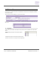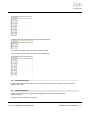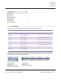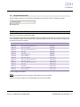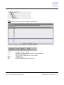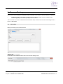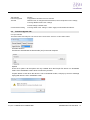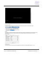
1
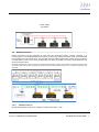
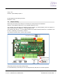
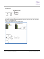
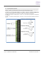
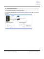
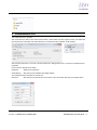
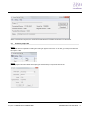
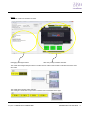
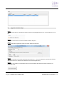
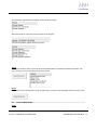
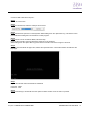
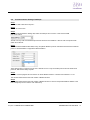
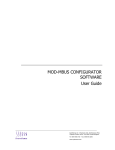
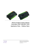
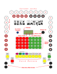
SDC-20C (FC20) Sedona Zone Controller User Manual SyxthSense Ltd. 3 Topsham Units. Dart Business Park. Topsham. Exeter. Devon. EX3 0QH. United Kingdom. Tel: 0844 840 3100 www.syxthsense.com Fax: 0844 840 3200 Copyright Notice This document has been prepared by SyxthSense Limited using (i) its own proprietary information and (ii) proprietary information owned and controlled by other third parties (for which SyxthSense Limited has a right to use). The contents are copyrighted and must not be communicated in whole or in part to any other party without the prior written approval of SyxthSense Limited. The following notice applies to this document and shall be reproduced on any permitted copies: © 2014 SyxthSense Limited. All rights reserved. Any request for further information concerning this document should be addressed to: SyxthSense Limited 3 Topsham Units Dart Business Park Topsham Exeter EX3 0QH United Kingdom Online Store: www.syxthsense.com Enquiries: T: 0844 840 3100 F: 0844 840 3200 Copyright 2014 SyxthSense Ltd. - Ver 0.2 SDC-AN18 CPT Tool User Guide 2 CONTENTS 1 INTRODUCTION ......................................................................................................................................... 4 2 PREREQUISITE ......................................................................................................................................... 10 3 2.1 EASYIOFC SEDONA KITS ......................................................................................................................... 11 2.2 EASYIOFC SEDONA PLATFORM FILES ...................................................................................................... 11 VIRTUALDEVICEFC20 ............................................................................................................................ 12 3.1 CREATE A PROJECT FILE .......................................................................................................................... 13 4 PROGRAMMING SDC-20C (FC-20) DEVICE ....................................................................................... 15 5 FC SEDONA KITS...................................................................................................................................... 19 5.1 EASYIOFC20 ........................................................................................................................................... 19 5.2 EASYIOFC20CONTROL ............................................................................................................................ 20 5.3 EASYIOFC20HVAC ................................................................................................................................ 20 5.4 EASYIOFC20REGS................................................................................................................................... 21 5.5 EASYIOFC20TEMPTABLE........................................................................................................................ 22 6 TEMPERATURE TABLE ......................................................................................................................... 22 7 FIRMWARE FLASHING .......................................................................................................................... 24 7.1 FC FWTOOL ............................................................................................................................................ 24 7.2 FIRMWARE UPGRADE TAB ...................................................................................................................... 25 7.3 UPGRADE FIRMWARE STEPS ................................................................................................................... 28 7.4 TERMINAL MODE STEPS.......................................................................................................................... 29 7.5 COMMUNICATIONS SETTINGS TAB STEPS ............................................................................................... 32 8 DISCLAIMER ............................................................................................................................................. 33 9 DOCUMENT CONTROL .......................................................................................................................... 34 Online Store: www.syxthsense.com Enquiries: T: 0844 840 3100 F: 0844 840 3200 Copyright 2014 SyxthSense Ltd. - Ver 0.2 SDC-AN18 CPT Tool User Guide 3 1 Introduction SyxthSense SDC-20C (FC-20) series controller is a competitive controller. It can serves as a dumb IO module or it can be program with limited standalone logic. It is not a Sedona controller but it can be program via a Sedona workbench. The virtual device will create a virtual Sedona running in the windows environment to replicate the Sedona VM. No new software tool to learn. No new programming concept to learn. Reuse the Sedona workbench knowledge. Same programming concept as SDC-xG Series. Limited resources up to 150 objects or 5MB memory which ever come first. The virtual device can then be connected to a hardware and download the program into the controller. The controller will have the program in the flash memory until it is been overwrite by another program. 2 Hardware Configurations 2.1 Power supply Connection Both AC and DC can be used for SDC-20C controller. Refer to electrical specification for the working range. In order to avoid damage on the controller input/output devices and RS485 connection, use individual power supply for each controller. If a single power supply is used, make sure controller power supplies are connected with the same polarity. Online Store: www.syxthsense.com Enquiries: T: 0844 840 3100 F: 0844 840 3200 Copyright 2014 SyxthSense Ltd. - Ver 0.2 SDC-AN18 CPT Tool User Guide 4 Power Supply Connection 2.2 RS485 Connection RS485 connection must be terminated at both ends with termination resistor, typically 120Ohms. It is recommended to use shielded twisted pair wire (STP) for the wiring. Lightning protection circuit is recommended to be installed at one end of the wiring. The controller should be wired in daisy chain network topology as shown as image below. If wire branch can be avoided, keep it as short as possible, and never connect more than one device to the wire branch. Be careful if single power supply is used for all connected RS485 device, make sure all devices are having the same ground connection. Make sure you are connecting the same wire for the same terminal position, all “H” terminals connected to the same wire. 2.2.1.1 RS485 Connection By default the Modbus serial comm. settings is as below. Baud Rate : 19.2K Online Store: www.syxthsense.com Enquiries: T: 0844 840 3100 F: 0844 840 3200 Copyright 2014 SyxthSense Ltd. - Ver 0.2 SDC-AN18 CPT Tool User Guide 5 Parity : even Data Bit : 8 (Not editable) Stop Bit : 1 By default BACnet serial settings as below Baud Rate : 19.2K 2.3 Jumpers Setting Below image shows the jumper setting for Universal Input, Analog Output, BACnet/Modbus Selection, and the BACnet MSTP ID (1~127) or Modbus Serial ID (1~127). The controller comes with BACnet and Modbus protocols selection. By default, Modbus protocol is selected. To switch to BACnet protocol, toggle the ‘1’ of the dip switch to ON. The remaining DIP switch ‘2’ ~ ‘8’ are for BACnet MSTP ID or Modbus Serial ID (address 0 is not available; it will be set to 1) depending on DIP switch 1 selection. Any changes to the DIP switch, a power cycle is needed. Image below show the DIP switch settings details. For serial addressing it uses binary bit. The Least Significant Bit (LSB) isDIP 8. The Most Significant Online Store: www.syxthsense.com Enquiries: T: 0844 840 3100 F: 0844 840 3200 Copyright 2014 SyxthSense Ltd. - Ver 0.2 SDC-AN18 CPT Tool User Guide 6 Bit (MSB) is DIP 2. 2.4 Digital Output Wiring Connection SDC-20C has four general purpose isolated digital output connections (relay output). Each relay output able to drive up to 1A 30VDC/ 48VAC load. It does not output voltage or current. It is a dry relay contact. Online Store: www.syxthsense.com Enquiries: T: 0844 840 3100 F: 0844 840 3200 Copyright 2014 SyxthSense Ltd. - Ver 0.2 SDC-AN18 CPT Tool User Guide 7 2.5 Universal Input Connection SDC-20C has twelve non-isolated universal inputs. The universal input supports three type of analog signal i.e. resistance, voltage and current transmitter via hardware jumper and internal register settings: a) Resistance – The working range of resistance is 0 – 30Kohms. If the input is configured as Thermistor type, the system provides 8 customizable temperature lookup tables for resistance to temperature translation. The commonly used Thermistor like 10K, 10K with Shunt, 1K Balco and 1K Platinum are all supported b) Voltage – Two selection of working range 0 – 5V and 0 – 10V. The minimum input impedance of voltage input is 1 Mega Ohm. c) Current – Two selection of working ranges 0 – 20mA and 4 – 20mA. The current input impedance is less than 25 Ohm. Online Store: www.syxthsense.com Enquiries: T: 0844 840 3100 F: 0844 840 3200 Copyright 2014 SyxthSense Ltd. - Ver 0.2 SDC-AN18 CPT Tool User Guide 8 2.6 Analog Output Connection SDC-20C has four Analog Output connections. Each Analog Output can be configured to drive voltage or current output via hardware jumper setting and internal register settings. The working range for voltage is 0 – 10V and for current either 0 – 20mA or 4 – 20mA. For current transmitter, the circuit able to drive load impedance up to 800 ohm which is ideal for long wire connection (up to 500 meter wire length). Online Store: www.syxthsense.com Enquiries: T: 0844 840 3100 F: 0844 840 3200 Copyright 2014 SyxthSense Ltd. - Ver 0.2 SDC-AN18 CPT Tool User Guide 9 3 Buttons and Indications The controller will do a hardware reset when the Reset Button is pressed whenever manual restart is required. The Service button is used to activate the built-in bootloader program for software upgrade. Each digital output has a correspondence LED to indicate its current state. LED Conditions Description 1 PWR PWR is used to indicate the presence of 24VAC power source, and internal power 2 ERR ERR is to indicate whenever there is communication errors. 3 STS STS is used to indicate the heartbeat of the Microcontroller. The STS LED will blink at 1-second interval in normal operation condition. 4 TXRX TXRX is used to indicate when there are communication activities (Transmitting or Receiving) on the communication port. 4 Software Prerequisite It is good to refer also to the Firmware Flashing section. Below are files needed to be copied into the host PC. Apart from the below files a USB to RS-485 converter is needed in order to proceed for program downloading. Any equivalent USB to RS-485 converter can be use. No 1. 2. Item VirtualDeviceFC20 easyioFC Niagara module 3. 4. Sedona kits for FC-20 Sedona platform files for FC-20 Description This is the controller Emulator. This module is for FC controller temp table settings. Sedona kits. These kits are fixed Sedona platform files. VirtualDeviceFC20 This is a program to emulate the FC device in the windows environment. Online Store: www.syxthsense.com Enquiries: T: 0844 840 3100 F: 0844 840 3200 Copyright 2014 SyxthSense Ltd. - Ver 0.2 SDC-AN18 CPT Tool User Guide 10 **Remarks All the files above have to be in a same root folder. easyioFC.jar Java module for Niagara workbench to be able to view the temp table UI. It has to be drop into the Niagara installation modules folders. Different Sedona version needs different jar file. Rename the jar files provided to easyioFC.jar or else it will not work. 4.1 easyioFC Sedona kits These are the kits that need to be in the Sedona kits folder. Copy these files and paste it into the Sedona/kits folder. 4.2 easyioFC Sedona platform files These sedona platform files that need to be in the Sedona platform folder. Copy these files and paste it into the Sedona/platform/db/ folder. Online Store: www.syxthsense.com Enquiries: T: 0844 840 3100 F: 0844 840 3200 Copyright 2014 SyxthSense Ltd. - Ver 0.2 SDC-AN18 CPT Tool User Guide 11 5 VirtualDeviceFC20 The virtual device UI is as below. The virtual device is able to show the firmware version, serial number and also register version if an SDC-20C (FC-20) device is connected. If the virtual device is not connected to any hardware, it will as below. The port drop down menu is for use to set the serial comm. settings that is use to connect to the SDC-20C (FC20) device. In this case, the settings are as below Serial Port Serial port use selection Serial settings SDC-20C (FC-20) hardware pre-define settings. This settings are done using the FC FwTool.exe. Device ID SDC-20C (FC-20) devices ID to be connect. This is set via the SDC-20C (FC-20) DIP switch. Online Store: www.syxthsense.com Enquiries: T: 0844 840 3100 F: 0844 840 3200 Copyright 2014 SyxthSense Ltd. - Ver 0.2 SDC-AN18 CPT Tool User Guide 12 When connect button is press, the virtual device will obtain the hardware information from the device. 5.1 Create a project file Step 1 The virtual device is capable of creating and saving an apps for future use. To do this, go to drop menu File and hit Project > New. Step 2 Put in a project name and select the Project type as SDC-20C (FC-20) HVAC then hit OK. Online Store: www.syxthsense.com Enquiries: T: 0844 840 3100 F: 0844 840 3200 Copyright 2014 SyxthSense Ltd. - Ver 0.2 SDC-AN18 CPT Tool User Guide 13 Step 3 The virtual machine UI will looks as below. Debugging messages window SDC-20C (FC-20) Hardware emulator The virtual device Digital Output indicator. The Box will turn Yellow when the DO is ON state and Green when OFF state. The virtual device Analog Output indicator. The Analog box will show the output value of what is been commanded in the apps. Online Store: www.syxthsense.com Enquiries: T: 0844 840 3100 F: 0844 840 3200 Copyright 2014 SyxthSense Ltd. - Ver 0.2 SDC-AN18 CPT Tool User Guide 14 The virtual device Universal Input as Digital Input Status. Toggle switch to activate the Digital Input. When DI is toggle, the Universal Input will show value 51.00 when true and value 44.00 when value is false. Virtual Device Universal Input Indicator/Simulator. Enter a value in here and it will show in the Sedona workbench. 6 Programming SDC-20C (FC-20) device Step 1 Connect a USB to Rs-485 converter to the PC. Step 2 Launch the Virtual Device FC-20.exe. Some anti-virus might block it to run. Step 3 Configure the COM port settings use. To check the COM port please go to My Computer > Properties > Device Manager (Windows 7). Step 4 In order to program the SDC-20C (FC-20), the protocol has to set to Modbus. DIP switch 1 = Off. Online Store: www.syxthsense.com Enquiries: T: 0844 840 3100 F: 0844 840 3200 Copyright 2014 SyxthSense Ltd. - Ver 0.2 SDC-AN18 CPT Tool User Guide 15 Step 5 To test the connection between the Virtual Device and also the SDC-20C (FC-20) hardware, hit connect at the virtual device program. A successful connection will show the SDC-20C (FC-20) hardware details. Step 6 Make sure the virtual device program is running in the PC or the host. The virtual device can be running in a remote host. It is not necessary to run in the local host. Step 7 Using the Sedona workbench or CPT tool, connect to the SDC-20C (FC-20) device via open Sedona (Sedona workbench), open device (CPT tool). In this case, the virtual device is running in a local host. Online Store: www.syxthsense.com Enquiries: T: 0844 840 3100 F: 0844 840 3200 Copyright 2014 SyxthSense Ltd. - Ver 0.2 SDC-AN18 CPT Tool User Guide 16 Step 8 You will see the Sedona programming environment. Remember SDC-20C (FG-20) is not a Sedona controller; it is just using the Sedona workbench or CPT tool to program it. All objects/programming can only be done in the “FC20” folder. Dropping components/objects in to other folder might cause issues later. Step 9 The program right now will reflect the virtual device. The virtual device will run as it is an SDC-xG Virtual Device. The virtual device is running real time. It will show real time values when engineering via Sedona workbench or CPT tool. Online Store: www.syxthsense.com Enquiries: T: 0844 840 3100 F: 0844 840 3200 Copyright 2014 SyxthSense Ltd. - Ver 0.2 SDC-AN18 CPT Tool User Guide 17 Step 10 Once programming is done, the program can then be downloaded to the SDC-20C (FC-20) hardware via the virtual device. Just hit download and the program will be downloaded into the hardware. The program will run right after the download process is done. The project will also download the temp table set via the workbench or CPT tool. Every download will overwrite the program in the SDC-20C (FC-20). Step 11 The program done in workbench or CPT tool can be backup as it is a project created as mention is the previous chapter. To save the project just go to File > Save (Save As). The saved file extension is “.vd” To reuse the backup, just open the project via Virtual Device and then connect Sedona via workbench or CPT tool to modify. When done, the apps can then be downloaded to the SDC-20C (FC-20) device. Online Store: www.syxthsense.com Enquiries: T: 0844 840 3100 F: 0844 840 3200 Copyright 2014 SyxthSense Ltd. - Ver 0.2 SDC-AN18 CPT Tool User Guide 18 7 FC Sedona Kits Each SDC-20C FC controller comes with a set of predefined kits. These kits are not manageable. No additional kits are allowed to install. There are total of 5 kits are available to use. The 5 kits are as below. Kits Name Description easyioFC20 I/O objects for SDC-20C (FC-20) easyioFC20Control Control objects easyioFC20Regs Register Objects to export either Bacnet or Modbus points easyioFC20HVAC HVAC objects such as PID loop, drive easyioFC20TempTable TempTable Object to configure temp table In order to engineer the SDC-20C (FC-20) controller, user will also need the below kits. Kits below need to be at least 1.0.48. Kits Name Inet.kit Sox.kit Sys.kit 7.1 Minimum version 1.0.48 1.0.48 1.0.48 easyioFC20 This kit contains all I/Os objects. These objects can only be use one time. Any duplication of the object will be discard. 4 Analogue Output (AO) objects. Each represent respective channel. 12 Digital Input (DI) objects. Each represent respective channel. **Note:f DI1 is use, then UI1 is no longer use as an analogue input. Online Store: www.syxthsense.com Enquiries: T: 0844 840 3100 F: 0844 840 3200 Copyright 2014 SyxthSense Ltd. - Ver 0.2 SDC-AN18 CPT Tool User Guide 19 4 Digital Output (DO) objects. Each represent respective channel. 12 Universal Input objects. Each represent respective channel. **Note: if UI1 is use, then DI1 is no longer use as a digital input. 7.2 easyioFC20Control This kit contains all the control objects. The control objects are from Sedona control kit. All source code are available from Sedona. 7.3 easyioFC20HVAC This kit contains all the control objects for HVAC applications. The control objects are from Sedona control kit. All source codes are available from Sedona. Online Store: www.syxthsense.com Enquiries: T: 0844 840 3100 F: 0844 840 3200 Copyright 2014 SyxthSense Ltd. - Ver 0.2 SDC-AN18 CPT Tool User Guide 20 7.4 easyioFC20Regs This kit contains register objects. Each type comes with max 16 register addresses. Type Register Type Total Number of Register Bool Boolean Read Only 16 BoolWr Boolean Writable 16 Float Float Read Only 16 (combine/share with Long) FloatWr Float Writable 16 (combine/share with LongWr) Long Long Read Only 16 (combine/share with Float) LongWr Long Writable 16 (combine/share with FloatWr) Short Integer Read Only 16 ShortWr Integer Writable 16 These register address will represents in Modbus or Bacnet automatically base on address and name created. See example below. The register Bool with address 2000 for Modbus and BACnet. As for BACnet, when doing points discovery, the name of the object will appear. Modbus Register Address: 2000 Data Type : Discrete Input Address Base : Zero Base BACnet Object Object ID : BV 21 Data Type : Binary Value Online Store: www.syxthsense.com Enquiries: T: 0844 840 3100 F: 0844 840 3200 Copyright 2014 SyxthSense Ltd. - Ver 0.2 SDC-AN18 CPT Tool User Guide 21 7.5 easyioFC20TempTable This kit contains an object for configuring the temp table for the FC device. See next chapter for details. 8 Temperature table SDC (FC-20) comes with 16 temperature table. These temperature table settings only available in Sedona workbench at the moment. It cannot be done in CPT tool. 8 temperature tables are user defines and 8 temperature tables are read only. Below are the 16 tables that by default come with the controller. Table number Table 01 Table 02 Table 03 Table 04 Table 05 Table 06 Table 07 Table 08 Table 09 Table 10 Table 11 Table 12 Table 13 Table 14 Table 15 Table 16 Sensor Type NTC 10K Type 2 NTC 10K Type 2 Shunt 11K NTC 10K Type 3 NTC 10K Type 3 Shunt 11K NTC 3K NTC 20K RTD 1K Platinum RTD 1K Balco NTC 10K Type 2 NTC 10K Type 2 Shunt 11K NTC 10K Type 3 NTC 10K Type 3 Shunt 11K NTC 3K NTC 20K RTD 1K Platinum RTD 1K Balco Remarks Editable Editable Editable Editable Editable Editable Editable Editable Read-only Read-only Read-only Read-only Read-only Read-only Read-only Read-only How to configure Temp Table Step 1 Drop the TempTable object from the easyioFCTempTable into the FC20 folder. *Make sure to drop the object in to the FC20 folder and not the service folder Online Store: www.syxthsense.com Enquiries: T: 0844 840 3100 F: 0844 840 3200 Copyright 2014 SyxthSense Ltd. - Ver 0.2 SDC-AN18 CPT Tool User Guide 22 Step 2 Double click on the object to bring up the temperature user interface. Only Table 1 to Table 8 is editable. Table 9 to Table 16 is pre-defined . Default Add Delete Edit Save Applicable to Table 1 to Table 8. It will restore the default value according to the type stated above. To add a row. Max of 30 rows. If 30 rows are in the table, this button will be disable. To delete a row To edit the row value. Save the changes made to the flash memory Online Store: www.syxthsense.com Enquiries: T: 0844 840 3100 F: 0844 840 3200 Copyright 2014 SyxthSense Ltd. - Ver 0.2 SDC-AN18 CPT Tool User Guide 23 9 Firmware Flashing All FC series comes with build in bootloader. Build in bootloader comes handy for firmware flashing or updating. • • The Build bootloader can only be carried out directly. It does not support remote bootloader mode. Firmware upgrading is via software package “FC FwTools.exe”. The FC FwTool.exe comes in a bundle with the bootloader mode, terminal mode and also serial settings mode. It is a 3 in 1 tool bundle 9.1 FC FwTool Below is how the FC FwTool user interface. Selection Tab Three selection tab available. Bootloader mode, Terminal mode and also Communication settings mode. Online Store: www.syxthsense.com Enquiries: T: 0844 840 3100 F: 0844 840 3200 Copyright 2014 SyxthSense Ltd. - Ver 0.2 SDC-AN18 CPT Tool User Guide 24 Tab Selection Firmware Upgrade Terminal Function To upgrade the firmware of the FC controller Terminal mode, to change the Bacnet device ID, bacnet mstp serial comm. settings, To change Modbus serial comm. settings Communication Setting 9.2 To reset settings to default value To change serial comm. setting in a batch. Apply for both Modbus and Bacnet. Firmware Upgrade Tab Com port selection This field to select the COM port to be use for the FC FwTool.exe at the PC. In this case it COM3. Firmware selection This field is to select/locate the firmware file (.bin) in the local computer. Options There are 3 options. All the options are only useable when the EasyIO FC device is in bootloader mode. Out of bootloader mode it does not serve any function. If option button is click when the device is not in bootloader mode, it will pop up an error message saying that device is not in bootloader mode. Online Store: www.syxthsense.com Enquiries: T: 0844 840 3100 F: 0844 840 3200 Copyright 2014 SyxthSense Ltd. - Ver 0.2 SDC-AN18 CPT Tool User Guide 25 Options Device Firmware Upgrade Device Firmware Detail Device firmware Run Function To upgrade the firmware of the SDC-20 FC device according to the firmware selected at the firmware selection field. To retrieve the firmware information when SDC-20C FC device in bootloader mode. To kick the bootloader mode into running mode. Output messages window This window shows the debugging messages of each option above. Terminal Tab Com port selection This field to select the COM port to be use for the FC FwTool.exe at the PC. In this case it COM3. Working window This window here shows the selection when the program successfully connected to the SDC-20C FC device. Online Store: www.syxthsense.com Enquiries: T: 0844 840 3100 F: 0844 840 3200 Copyright 2014 SyxthSense Ltd. - Ver 0.2 SDC-AN18 CPT Tool User Guide 26 Communication Setting Tab Com port selection This field to select the COM port to be use for the FC FwTool.exe at the PC. In this case it COM3. Setting This window is to define the Modbus or BACnet serial comm. settings to be edited for all connected device in the bus. When set button is hit, it will set the serial comm. settings to the entire scanned device in the device window below. Device Window This window shows the total number of available device in the bus. Scanning address range is 1 ~ 127. Online Store: www.syxthsense.com Enquiries: T: 0844 840 3100 F: 0844 840 3200 Copyright 2014 SyxthSense Ltd. - Ver 0.2 SDC-AN18 CPT Tool User Guide 27 9.3 Upgrade Firmware Steps Step 1 Get the required files from SyxthSense technical support at [email protected]. The firmware file is a .bin file. Step 2 Launch FC FwTool.exe. and connect USB to RS-485 to the port 1. Step 3 Under the firmware upgrade tab, locate the .bin file. Select the COM port. Step 4 While the controller is in ON mode, hold down both buttons for 1 second and release the reset button( left side ) , wait for the STS Led to flash fast and release the service button(right button). Step 5 Make sure the controller is in bootloader mode. The status LED will flash approx 5Hz when the device is in bootloader mode. Online Store: www.syxthsense.com Enquiries: T: 0844 840 3100 F: 0844 840 3200 Copyright 2014 SyxthSense Ltd. - Ver 0.2 SDC-AN18 CPT Tool User Guide 28 Hit the firmware upgrade button. Message window will show as below. Status bar at bottom of the FC FwTool.exe will show the progress. A successful firmware upgrade will show as below. Step 6 To verify the firmware version, hit the Device Firmware Detail button to retrieve the firmware information. This step can be skip if you are sure about the firmware version. Step 7 Hit the Device Run Firmware button to kick the SDC-20C (FC) device out of bootloader mode into running mode. 9.4 Terminal Mode Steps Step 1 Online Store: www.syxthsense.com Enquiries: T: 0844 840 3100 F: 0844 840 3200 Copyright 2014 SyxthSense Ltd. - Ver 0.2 SDC-AN18 CPT Tool User Guide 29 Connect a USB to RS-485 to the port 1. Step 2 Launch FC FwTool.exe. Step 3 Under the Terminal tab, select the COM port and Connect. Step 4 Press and hold down space bar on the keyboard. While holding down the “Space Bar” key, note that the comm. LED will blink fast stating that communication is under progress. Step 5 If the protocol is set to run BACnet MSTP, follow this step. Power off the controller, press and hold down space bar on the keyboard. While holding down the “Space Bar” key power ON the controller. Hold down for approx 5 seconds. Step 6 When the STS LED blinks at approx 5Hz, release the space bar button. The terminal window should show the login page. Step 7 Login to the terminal mode with the below credentials. Username : admin Password : 1234 Step 8 After successful login, window will show the options as below. Select one of the menu to proceed. Online Store: www.syxthsense.com Enquiries: T: 0844 840 3100 F: 0844 840 3200 Copyright 2014 SyxthSense Ltd. - Ver 0.2 SDC-AN18 CPT Tool User Guide 30 I. Serial Port : Read only, shows the protocol selection done which done by setting the DIP switch 1. II. Modbus : Menu to change the Modbus serial settings. III. Bacnet : Menu to change the Bacnet serial settings. To change the BACnet ID is in this menu. IV. Username : This is to change the terminal mode username. V. Password : This is to change the terminal mode password. VI. Reset Setting to Default Value: This is to reset all the settings done for I/Os VII. Device information: Shows the device firmware information. VIII. Exit: To kick the controller out of terminal mode to normal running mode. Step 9 When settings are done, hit “ESC” keyboard button to return to previous menu. Choose selection 8 to exit the terminal mode or else press the onboard reset button. Online Store: www.syxthsense.com Enquiries: T: 0844 840 3100 F: 0844 840 3200 Copyright 2014 SyxthSense Ltd. - Ver 0.2 SDC-AN18 CPT Tool User Guide 31 9.5 Communications Settings Tab Steps Step 1 Connect a USB to RS-485 to the port 1. Step 2 Launch FC FwTool.exe. Step 3 Under the Communications Settings tab, select the COM port and Connect. In this case the COM port use is COM 3. This tab can only work if the hardware protocol DIP switch is set to Modbus. It will not work if the protocol DIP switch set to BAcnet. Step 4 Choose the desire Modbus Baud Rate, Parity, Stop Bit for Modbus protocol or/and BACnet baud rate for BACnet protocol. Auto Baud Rate is supported for BACnet MS/TP. These settings are to configure only the Port 1 RS-485. Port 2 is only for Modbus protocol and the baud rate is preset at ; Baud Rate: Parity: Stop Bit. Step 5 Hit “Scan” and the program will scan the bus for all the Modbus devices. It will scan from address 1 to 127. The window below will show the total number of Modbus devices. Step 6 The window below will show the total number of Modbus devices. If there is an duplicate Modbus address in the bus, it will prompt an error and the scan will be stop. Online Store: www.syxthsense.com Enquiries: T: 0844 840 3100 F: 0844 840 3200 Copyright 2014 SyxthSense Ltd. - Ver 0.2 SDC-AN18 CPT Tool User Guide 32 Step 7 Hit Set button and the program will set the selected serial settings to all the device listed in the window. The device do not need a power cycle or reboot for the serial settings to take effect. Try rescanning again to confirm the serial settings. 10 Disclaimer The SDC-30, SDC-20C, SDC-20G and SDC-32G controllers are was built on the Sedona Framework ®. Sedona Framework is a trademark of Tridium, Inc. CPT Tool is by Online Tools Inc. Online Store: www.syxthsense.com Enquiries: T: 0844 840 3100 F: 0844 840 3200 Copyright 2014 SyxthSense Ltd. - Ver 0.2 SDC-AN18 CPT Tool User Guide 33 11 Document Control Version Date 0.1 18-Feb-2014 Original Release 0.2 04-Jun-2014 Hardware Configuration Details Added Online Store: www.syxthsense.com Enquiries: T: 0844 840 3100 F: 0844 840 3200 Change History Copyright 2014 SyxthSense Ltd. - Ver 0.2 SDC-AN18 CPT Tool User Guide 34 SyxthSense Limited 3 Topsham Units Dart Business Park Exeter EX3 0QH United Kingdom Enquiries: T: 0844 840 3100 F: 0844 480 3200 Online store: www.syxthsense.com Online Store: www.syxthsense.com Enquiries: T: 0844 840 3100 F: 0844 840 3200 Copyright 2014 SyxthSense Ltd. - Ver 0.2 SDC-AN18 CPT Tool User Guide 35