1
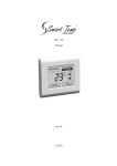
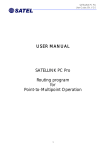
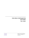
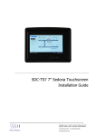
SRC-131 Modbus Hotel Room Controller User Manual SyxthSense Ltd. 3 Topsham Units. Dart Business Park. Topsham. Exeter. Devon. EX3 0QH. United Kingdom. Tel: 0844 840 3100 Fax: 0844 840 3200 www.syxthsense.com Copyright Notice This document has been prepared by SyxthSense Limited using (i) its own proprietary information and (ii) proprietary information owned and controlled by other third parties (for which SyxthSense Limited has a right to use). The contents are copyrighted and must not be communicated in whole or in part to any other party without the prior written approval of SyxthSense Limited. The following notice applies to this document and shall be reproduced on any permitted copies: © 2012 SyxthSense Limited. All rights reserved. Any request for further information concerning this document should be addressed to: SyxthSense Limited 3 Topsham Units Dart Business Park Topsham Exeter EX3 0QH United Kingdom Online Store: www.syxthsense.com Enquiries: T: 0844 840 3100 F: 0844 840 3200 Copyright 2012 SyxthSense Ltd. SRC-131 Hotel Controller Manual 2 CONTENTS 1 INTRODUCTION ...................................................................................................................... 4 2 CONTROLLER OPERATION ................................................................................................ 4 3 INSTALLATION ....................................................................................................................... 5 3.1 3.2 3.3 3.4 4 WIRING EXAMPLES .............................................................................................................. 6 4.1 4.2 4.3 4.4 5 HEAT PUMP SYSTEM - 3 FAN SPEED ..................................................................................... 6 HEAT COOL SYSTEM - 1 FAN SPEED...................................................................................... 6 0-10V HEATING VALVE WITH COOL - 1 FAN SPEED ............................................................ 6 MAINS POWERED COOLING VALVE - 3 FAN SPEED ............................................................... 7 WIRING EXAMPLES – ANCILLARY FUNCTIONS ......................................................... 7 5.1 5.2 5.3 5.4 5.5 5.6 6 SYSTEM DESIGN .................................................................................................................... 5 WALL CONTROLLER .............................................................................................................. 5 WIRING TERMINALS .............................................................................................................. 5 DIP SWITCH SETTINGS .......................................................................................................... 5 COMPLETE SYSTEM OVERVIEW............................................................................................. 7 MODBUS WIRING ................................................................................................................... 7 OCCUPANCY INPUT ................................................................................................................ 8 OUTSIDE DOOR STATION ....................................................................................................... 9 REMOTE TEMPERATURE SENSORS ......................................................................................... 9 DOORBELL ............................................................................................................................. 9 INSTALLER OPTIONS MENU ............................................................................................ 10 6.1 NAVIGATING THROUGH THE INSTALLER MODE SETTINGS ................................................. 10 6.2 OPTION LIST TABLE ............................................................................................................. 10 6.3 MODBUS DATA .................................................................................................................... 11 6.3.1 Data Format ................................................................................................................ 12 7 SPECIFICATIONS .................................................................................................................. 14 Online Store: www.syxthsense.com Enquiries: T: 0844 840 3100 F: 0844 840 3200 Copyright 2012 SyxthSense Ltd. SRC-131 Hotel Controller Manual 3 1 Introduction The SRC-131 controller has been designed for use in hotel rooms and other locations where the user may be unfamiliar with controller operations. In these applications it is important that the controller be very intuitive, robust and attractive. The SRC-131 controller has been designed with these important goals is mind. The SRC-131 also offers advanced energy conservation features such as set point limit control, un-occupied heating and cooling settings as well as Modbus RTU communications for integration with the “Building Automation System” (BAS) or “Hotel Check In” system. Additionally, the SRC-131 seamlessly interfaces with the “Door Station” system. 2 Controller Operation The SRC-131is an extremely simple controller to operate and does not normally require a user manual or user training. The diagram to the left shows all LCD elements and the 6 buttons (Up / Down / Make Up Room / Do Not Disturb / On – Off / Fan Mode. Depending on switch and installer menu settings not all segments maybe shown. On/Off Tap the On/Off button to turn the controller On or Off. Set Temperature Adjust the target temperature with the Up or Down button. Fan Single fan speed mode (Sw1=Off) Tap the fan button to cycle between auto fan and continuous fan mode. Three fan speed mode (Sw1=On) Tap the fan button to cycle between low, medium, high and auto fan speeds. Press and hold the fan button to turn the fan on continuously. Note. Option 16 in the installer menu can set the SRC-131 to reset the indoor fan to Automatic Mode (cycle on and off with heating and cooling) every time the controller is turned off. Ventilation Mode If permitted by DIP Sw7, the user can run the indoor fan only (Ventilation Mode) when the SRC-131 is off by tapping the fan button. Each tap of the fan button will cycle between all available fan speeds. “Make up Room” & “Do Not Disturb” Buttons When enabled by DIP Sw8, pressing these buttons will activate relevant LCD segments and backlight colour on the optional outside door station as well as write data to Modbus for monitoring by a BAS system. Online Store: www.syxthsense.com Enquiries: T: 0844 840 3100 F: 0844 840 3200 Copyright 2012 SyxthSense Ltd. SRC-131 Hotel Controller Manual 4 3 Installation 3.1 System Design Great effort has been taken to make the SRC-131system intuitive, reliable and easy to install. Using a common sense approach to the installation will ensure this product is installed easily and to the customer’s satisfaction. Please read and understand this instruction manual so that installation, testing and commissioning process is undertaken in an efficient and effective manner. 3.2 Wall Controller Open the SRC-131 wall controller by placing a flat blade screwdriver or coin in the slot on the bottom of the controller case and push in gently inwards to release the case locking clip. Gently pry the two case halves apart at the base taking care not to twist the case as this may crack the LCD. 3.3 Wiring Terminals B A 0 H C + W Y 3 2 1 Modbus Data B Modbus Data A 0..10V 0V Common Terminal 0..10V Heating Output 0..10V Cooling Output 24V Common 24V Active Heat (or reversing valve) Cool (or compressor) Fan Speed High Fan Speed Medium Fan Speed Low DD+ SS+ Digital 0 Volt Digital Input Active Sensor Input 0 Volt Sensor Input Active 3.4 DIP Switch Settings Switch Sw1 Sw2 Sw3 Function Indoor Fan Mode Equipment Type HP Mode (Sw2= ON) HC Mode (Sw2=OFF) Sw4 Sw5 Sw6 Sw7 Sw8 Not Used Comp Protection Delay Not Used Ventilation Mode Door Station (Optional) On 3 Fan Speed Heat Pump Rev Valve Heat (B) HE – Fan With Heat Off 1 Fan Speed Heat Cool Rev Valve Cool (O) HG – No Fan In Heat 5 Min Anti Cycle No Anti Cycle Permitted Fitted Not Permitted Door Station Not Used Note: The SRC-131 reads the switch settings on power up only. If you change any DIP switch settings you must cycle power or press the reset button before these changes will take effect. Online Store: www.syxthsense.com Enquiries: T: 0844 840 3100 F: 0844 840 3200 Copyright 2012 SyxthSense Ltd. SRC-131 Hotel Controller Manual 5 4 Wiring Examples Provided below are a few typical examples of wiring. These can be adapted to meet specific project or user needs. For example, heat pump 3 speed fan and heat pump single speed fan are in essence the same wiring except for DIP switch 1 position and the fan med and high speed terminal wiring. 4.1 Heat Pump System - 3 Fan Speed Switch Settings Sw1 = On - 3 Fan Speed Sw2 = On - HP Mode Sw3 = On/B Off/O Sw4 = N/A Sw5 = On - Comp Delay Sw-6 = Customer Pref Sw7 = Customer Pref 4.2 Heat Cool System - 1 Fan Speed Switch Settings Sw1 = Off - 1 Fan speed Sw2 = Off - HC Mode Sw3 = On/HE Off/HG Sw4 = N/A Sw5 = On - Comp Delay Sw6 = Customer Pref Sw7 = Customer Pref 4.3 0-10V Heating Valve With Cool - 1 Fan Speed Sw1 = Off - 1 Fan Speed Sw2 = Off - HC Mode Sw3 = On/HE Sw4 = N/A Sw5 = On - Comp Delay Sw6 = Customer Pref Sw7 = Customer Pref Online Store: www.syxthsense.com Enquiries: T: 0844 840 3100 F: 0844 840 3200 Copyright 2012 SyxthSense Ltd. SRC-131 Hotel Controller Manual 6 4.4 Mains Powered Cooling Valve - 3 Fan Speed Settings Sw1 = On - 3 Fan Speed Sw2 = Off – HC Mode Sw3 = On/HE Sw4 = N/A Sw5 = Off - No Delay Sw6 = Customer Pref Sw7 = Customer Pref When using a separate power supply for the valve, please ensure both power supply’s 0 volt terminals are joined so the 0-10V signal has a return path. In this example, the relay “Y” terminal could be used for a circulating water pump call if needed. 5 Wiring Examples – Ancillary Functions Additional capabilities can be used when wiring the SRC-131 to external devices. These include BAS, room occupancy detection systems, door card readers and the optional SyxthSense outside door stations. 5.1 Complete System Overview As can be seen by the diagram to the left, the SRC-131 is the hub of a sophisticated hotel room HVAC control and management system. Connecting the SRC-131 to an automatic occupancy detection system such as the SyxthSense SRC-OC (optional) permits you to precisely control HVAC energy consumption by automatically selecting a more economical room set temperature when the room is unoccupied. The optional door station connects quickly and easily to the SMT131. This provides the hotel guest with the ability to request privacy or call for housekeeping when needed. A doorbell function is also provided. Network communications enables the room to be “turned on” remotely as a guest arrives and “shut down” at checkout – further saving money on energy costs. 5.2 Modbus Wiring Modbus communications unlock many additional functions within the SRC-131 controller. It also permits all modes, functions and controls to be remotely supervised and adjusted from a central location if needed. Modbus object data can be found later on this manual. The SRC-131 uses a high powered Maxim chipset that will “theoretically” permit the connection of up to 255 devices on a single Modbus node. RF noises and other interferences will reduce the real world permitted connections to a maximum of 200 in most cases. Modbus and other communication protocol rely on the quality of cable and good installation practises Online Store: www.syxthsense.com Enquiries: T: 0844 840 3100 F: 0844 840 3200 Copyright 2012 SyxthSense Ltd. SRC-131 Hotel Controller Manual 7 to ensure reliable communications. Modbus requires the use of screen cable with the drain grounded in a single location. Hint! When the SRC-131 is connected to a working Modbus Network and receiving valid data, the decimal point in the temperature display will blink. If there is no communication or the SMT-131 is receiving corrupted data, this decimal point will remain on steady. Modbus relies on a series connection and will normally not tolerate “Star” wiring or “T” branches. 5.3 Occupancy Input When the room is detected “unoccupied” by a third party device or the optional SyxthSense SRC-OC occupancy detection system, the SRC131 will replace the user set point with installer pre-set temperatures or alternatively, turn the controller off. The user settings will return when the room is again occupied. The Digital Inputs in the SRC-131 are volt free. To initiate the “unoccupied” function simply bridge the D+ and D- terminals through a clean contact (switch or relay terminal). Online Store: www.syxthsense.com Enquiries: T: 0844 840 3100 F: 0844 840 3200 Copyright 2012 SyxthSense Ltd. SRC-131 Hotel Controller Manual 8 5.4 Outside Door Station When coupled with the optional SyxthSense door station the guest has the ability to set the room as “Do Not Disturb”, call for housekeeping or be alerted to visiting guests with a pleasant doorbell chime. Hotel staff are informed about the room status or guest’s needs by text information displayed on the door station LCD as well as the door station backlight colours. Connection between the SRC-131 and the hotel door station is by the supplied 1 metre cable fitted with RJ12 plugs. Longer cables up to 10 metres maximum can be supplied at extra cost. When fitting the door station, the SRC-131 DIP Sw8 must be ON. The outside door station will flash all LCD segments if DIP Sw8 is in the wrong position. 5.5 Remote Temperature sensors Occasionally the room controller cannot be installed in the ideal location to measure the room temperature accurately. In these circumstances the SRC-13 can use optional remote temperature sensors. These are a two wire device, not polarity dependent and simply wired into the SRC-131 sensor inputs terminals. Depending on installer menu sensor settings, shown on page 11, remote sensor(s) will either override the SRC-131 onboard sensor or average with the onboard sensor. Multiple sensors can be used for averaging over larger areas if necessary. Wireless (RF) remote sensors are also available if wiring cannot be installed economically. 5.6 Doorbell A built in doorbell feature is included with the SRC-131 controller. This is normally activated by the optional door station or via Modbus data link. In circumstances where this is not convenient, the digital input terminals can be assigned as a doorbell switch with the digital input options detailed in the installer menu on page 11. Simply place a momentary volt free switch across the S+ and S- terminals to activate the doorbell. Once pressed, the doorbell will chime for 10 seconds. Online Store: www.syxthsense.com Enquiries: T: 0844 840 3100 F: 0844 840 3200 Copyright 2012 SyxthSense Ltd. SRC-131 Hotel Controller Manual 9 6 Installer Options Menu The SRC-131 has an impressive list of options that can be installer selected. These options tune the controller’s performance as well as set energy conservation settings. This menu is deliberately hidden and difficult to enter to discourage unauthorised tampering. The 2 steps to enter the installer menu are: 1. 2. 6.1 Ensure that the controller is OFF Press and hold both the top left (make up my room button) and bottom right (fan mode) together for 10 seconds or until the display changes and shows “installer mode” Navigating Through The Installer Mode Settings The bottom right button steps forward through the menu options, the bottom left button steps you backwards. Adjust your options with the up/down buttons. Exit the menu saving changes by pressing and holding the bottom right (fan button) or waiting. The SRC131 will exit this menu automatically after 20 seconds. 6.2 Option List Table Option 0 1 2 3 4 5 6 7 8 9 10 11 12 Setting User Temperature 0 = Show Room and Set temperature (Default) Display 1 = Show Set Temperature Only Temperature Format C = Degrees Celsius (Default) F = Degrees Fahrenheit High Set Point Limit Off, then 5°C to 30°C (41°F to 95°F) (Default = 30°C) Low Set Point Limit Off, then 5°C to 30°C (41°F to 95°F) (Default = 5°C) User Set Point Dead 0.5°C to 5°C in 0.5°C Steps (Default = 1°C) Band Span (Relays - 0.5°C to 3°C in 0.5°C Steps (Default = 0.5°C) Hysteresis) Indoor Fan Purge 0 = Off 1 = Fan Purge - 1 Min 2 = Fan Purge - 3 Min 3 = Fan Purge - 5 Min 4 = Fan Purge - 10 Min 5 = Heat Only Fan Purge - 1 Min 6 = Heat Only Fan Purge - 3 Min 7 = Heat Only Fan Purge - 5 Min 8 = Heat Only Fan Purge - 10 Min 9 = Cool Only Fan Purge - 1 Min 10 = Cool Only Fan Purge - 3 Min 11 = Cool only Fan Purge - 5 Min 12 = Cool Only Fan Purge - 10 Min Note - A 15 second fan purge is applied in all modes 0-10 Volt Heat Span 0.5°C to 3°C in 0.5°C Steps (Default = 1°C) 0-10 Volt Cool Span 0.5°C to 3°C in 0.5°C Steps (Default = 1°C) Auto Off Timer Off, then 1 to 10 Hours in 30 Min Intervals (Default = OFF) Unoccupied Off, then 5°C to 30°C (41°F to 86°F) (Default = OFF) Heat Setoint Unoccupied Cool Set Off, then 5°C to 30°C (4°F1 to 86°F) (Default = OFF) Point Unoccupied Fan Mode 1 = Low (Auto) (Default), 2 = Med (Auto) 3 = High (Auto) 4 = Low (On) 5 = Med (On) 6 = High (On) Online Store: www.syxthsense.com Enquiries: T: 0844 840 3100 F: 0844 840 3200 Copyright 2012 SyxthSense Ltd. SRC-131 Hotel Controller Manual 10 6.3 13 Backlight 14 Sensor Input Functions 15 Digital Input Functions 16 Reset Indoor Fan Mode 17 Belimo Mode 18 19 Modbus Address Communications Baud “r” Factory Reset 0 = On With Button Press Only 1 = Always On (High Brightness) 2 = Low Then High With Button Press (Default) rS = Use In Place Of Onboard Sensor (Default) Au = Average Onboard And Remote Sensor dA = Display Sensor Value In Modbus Only OC = Initiate Unoccupied Mode (Default) db = Chime The Doorbell (Sw8 Must Be Off) 0 = Off (Default) 1 = On (If user sets fan to continuous mode, when the user turns the controller off the fan mode will reset back to automatic mode) 0 = Off (Default) 1 = On Defines 0-10V Output For Belimo 6 Way Actuator 1 to 255 (Default = 7) 0 = 4.8K 1 = 9.6K (Default) 2 = 19.2K 0 = Off (Default) 1 = Force Reset - Resets All Installer Settings Modbus Data The SRC-131 has integrated Modbus RTU communications. Using a Modbus master controller such as the SyxthSense Sedona SDC-30 many of the SRC-131 room controller features can be centrally controlled and monitored. Modbus is a simple protocol that is extremely popular due to its robustness and simple implementation. It is also a “forgiving” protocol and will tolerate many installation errors. This being stated however, correct wiring practices should be used to achieve maximum reliability. See earlier details on wiring Modbus networks. The SRC-131 Modbus data is within the “40XXX” range, this being holding registers. Depending on your choice of Modbus Master you may need to enter the address using the full address - such as “40012” or by selecting “Holding Registers” and entering the address simply as “12”. Online Store: www.syxthsense.com Enquiries: T: 0844 840 3100 F: 0844 840 3200 Copyright 2012 SyxthSense Ltd. SRC-131 Hotel Controller Manual 11 6.3.1 Data Format Protocol: Byte Format: Address: Baud: Modbus RTU 1 Start Bit, 8 Data Bits, 1 Stop Bit, No Parity 1 to 255 4800 / 9600 / 19200 BPS Holding Register 40001 40002 40003 Read Only Read Only Read Only 40004 Read / Write 40005 Read Only 40006 Read / Write Door Station Status 40007 Read / Write HVAC Status 40008 Read / Write Fan Status 40009 Read / Write User Set Point 40010 Read / Write Contact Reception Notification 40011 Read Only 40012 Read / Write 40013 Read/Write Room Temperature Temperature Display C/F Display 40014 Read / Write 40015 Read / Write 40016 Read / Write User Set Point High Limit User Set Point Low Limit Dead Band 40017 Read / Write Relay Span Type Online Store: www.syxthsense.com Enquiries: T: 0844 840 3100 F: 0844 840 3200 Value Comments Device ID Firmware Version DIP Switch Settings Occupancy Status Always Returns “131” Divide By 100 (e.g. Version 2.36 = 236) Binary Count Sw 1 = 1, Sw2 = 2, Sw3 = 4, Sw 4 = 8 etc 0 = Room is Unoccupied 1 = Room is Occupied Note - Modbus can write “0” holding the room unoccupied regardless of the occupancy input. Modbus cannot override the occupancy input and hold the SRC-131in occupied mode. 0 = Bell Is Silent 1 = Bell Is Chiming 0 = Normal - No Activity 1 = “Make Up Room” Active 2 = “Do Not Disturb” Active 0 = Air Conditioning Off (1 or 3 Fan Speed) 1 = Low Speed Ventilation ( 1 or 3 Fan Speed) 2 = Med Speed Ventilation (3 Fan Speed Only) 3 = High Speed Ventilation (3 Fan Speed only) 4 = Air Conditioning ON (1 or 3 Fan Speed) 3 Fan Speed Mode 0 = Low (Fan Auto) 1 = Med ( Fan Auto) 2= High (Fan Auto) 3 = Auto Fan Speed (Fan Auto) 4 = Low (Fan On) 5 = Med (Fan On) 6 = High (Fan On) 7 = Auto Fan Speed (Fan On) 1 Fan Speed Mode 0 = Fan Auto 4 = Fan On Deg C = 0.5°C Steps Deg F = 1°F Steps Value / 10 ( e.g. 23.5°C = 235) 0 = Off 1 = Show Contact Reception on LCD SRC-131LCD will flash “Contact Reception” on LCD and sound chime. User may accept alert by touching any button on SRC-131 Value / 10 (e.g. 21.7c = 217) Bell Status 0 = Show Room and Set Temperature 1 = Show Set Temperature Only 0 = Deg C format 1 = Deg F format 5°C to 30°C Range (41°F-86°F) in 1°C/F Steps 1:1 5°C to 30°C Range (41°f-86°F) in 1°C/F Steps 1:1 0.5°C to 5.0°C in 0.5°C Steps 1.0°F to 10.0°F in 1°F Steps Value / 10 (e.g. 1.5°C Dead Band = 15) 0.5°C to 3.0°C in 0.5°C Steps 1°F to 10°F in 1°F Steps Value / 10 (e.g. 1.0°C Span = 10) Copyright 2012 SyxthSense Ltd. SRC-131 Hotel Controller Manual 12 40018 Read / Write Fan Purge Period 40019 Read / Write 0-10V Heat Span 40020 Read / Write 0-10V Cool Span 40021 Read / Write Auto Off Timer 40022 Read /Write Unoccupied Heat Set Point 40023 Read / write Unoccupied Cool Set Point 40024 Read / Write Unoccupied Fan Mode 40025 Read / Write Backlight 40026 Read / Write Remote Temperature Input Function 40027 Read / Write 40028 Read / Write Digital Input Function Reset Fan Mode 40029 Read / Write Belimo Mode 40030 40031 Read / Write Read / Write Modbus Address Baud Rate 40032 Read Only 40033 Read Only 40034 Read Only 40035 Read Only Digital Input Status Internal Sensor Value Remote Sensor Value W relay status 40036 Read Only Y Relay Status Online Store: www.syxthsense.com Enquiries: T: 0844 840 3100 F: 0844 840 3200 0 = Off 1 = Fan Purge - 1 Min 2 = Fan Purge - 3 Min 3 = Fan Purge - 5 Min 4 = Fan Purge - 10 Min 5 = Heat Only Fan Purge - 1 Min 6 = Heat Only Fan Purge - 3 Min 7 = Heat Only Fan Purge - 5 Min 8 = Heat Only Fan Purge - 10 Min 9 = Cool Only Fan Purge - 1 Min 10 = Cool Only Fan Purge - 3 Min 11 = Cool Only Fan Purge - 5 Min 12 = Cool Only Fan Purge - 10 Min 0.5°C to 3°C in 0.5°C Steps 1°F to 6°F in 1°F Steps Value / 10 (e.g. Heat Span of 1°C= 10) 0.5°C to 3°C in 0.5°C Steps 1°F to 6°F in 1°F Steps Value / 10 (e.g. Cool Span of 1°C = 10) 0 = 0ff 1 to 10 Hours. Value / 10 (e.g. 3 Hour Auto Off Timer = 30) 0 = Off 5°C to 30°C in 0.5°C Steps 41°F to 86°F in 1°F Steps Value / 10 ( e.g. 17°C Unoccupied Heat = 170) 0 = Off 5°C to 30°C in 0.5°C Steps 41°F to 86°F in 1°F Steps Value / 10 ( e.g. 28.5°C Unoccupied Cool = 285) 3 Fan Speed Mode 1 = Low (Fan Auto) 2 = Med ( Fan Auto) 3 = High (Fan Auto) 4 = Low (Fan On) 5 = Med (Fan On) 6 = High (Fan On) 1 Fan Speed Mode 0 = Fan Auto 4 = Fan On 0 = On With Button Press 1 = Always On (High) 2 = Always On Low - High With Button Press 0 = Replace On Board Sensor With Remote 1 = Average Onboard Sensor With Remote 2 = Modbus Use Only (e.g. Coil Temp Monitor) 0 = Occupancy Initiate 1 = Chime Door Bell 0 = Leave Fan Mode Unchanged 1 = Reset Fan To Auto At Switch Off 0 = Standard 0-10V Valve Logic 1 = Belimo 6V = Off 3 Way Valve Logic 1 to 255 1 = 4.8Kbs 2 = 9.6kbs 3 = 19.2Kbs 0 = Open 1 = Closed Value / 10 (e.g. 23.3°C = 233) Value / 10 (e.g. 21.8°C = 218) 0 = Off 1 = Energised 0 = Off Copyright 2012 SyxthSense Ltd. SRC-131 Hotel Controller Manual 13 7 40037 Read Only 40038 Read Only 40039 Read Only 40040 40041 Read Only Read Only High Fan Relay Status Medium Fan Relay Status Low Fan Relay Status 0-10V Heat Value 0-10V Cool Value 1 = Energised 0 = Off 1 = Energised 0 = Off 1 = Energised 0 = Off 1 = Energised 0..100% (e.g. 7.3V = 73%) 0..100% (e.g. 2.1V = 21%) Specifications Input Voltage: Operating Temperature: Operating RH: Storage Temperature: Size: Display Size: Backlight: Display Type: Relay Rating: 0-10V Output Load: Control Range: Memory Type: Communications: Plastic: Warranty: Online Store: www.syxthsense.com Enquiries: T: 0844 840 3100 F: 0844 840 3200 24VAC 50/60 Htz +/- 15% 0°C to 50°C (32°F to 122°F) 0-95% (Non Condensing) 0°Cto 65°C (32°F to 150°F) 113 x 103 x 25mm. 69.5 x 46.3mm. White LED (Other Colours Available Upon Request) STN Touch Panel 30V @ 1Amp Max 10mA Max 5°C to 30°C (41°F to 86°F) Non Volatile - Settings Do Not Require Battery Backup Modbus RTU 4 .8K / 9.6K / 19.2 K, 1 Stop Bit, 8 Data Bits, 1 Start Bit. No Parity. ABS / Poly Blend – UV Stabilised and Fire Rated 2 Year RTB Copyright 2012 SyxthSense Ltd. SRC-131 Hotel Controller Manual 14 SyxthSense Limited 3 Topsham Units Dart Business Park Exeter EX3 0QH United Kingdom Enquiries: T: 0844 840 3100 F: 0844 480 2200 Online store: www.syxthsense.com Copyright 2012 SyxthSense Limited. All rights reserved. Online Store: www.syxthsense.com Enquiries: T: 0844 840 3100 F: 0844 840 3200 Copyright 2012 SyxthSense Ltd. SRC-131 Hotel Controller Manual 15