1
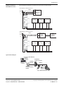
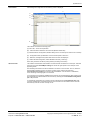
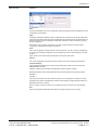
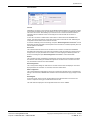
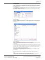
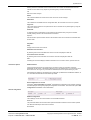
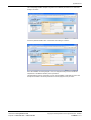
Product sheet SW4.06
Type MBUS-CONF
MBUS-CONF Modbus to M-Bus
Converter Module Software
The MBUS-CONF Configurator tool is used to parameter all
MBUS to MODBUS converter modules (MOD-M-BUS converters)
and administer the corresponding configurations. This means that
configurations can be either stored in files or can be read from or
written into the converter module. Due to a program manager the
meters and pulse counters can be easily and quickly configured.
Features
•
Easy configuration of the MOD-M-BUS Converters
•
Query of the parameterised data for easy functional tests
•
Configuration manager for quick selection of the meter bus
reader data
•
Runs under Windows® Win 2000 / Win XP
Model Type
Technical Data
Model
Description
MBUS-CONF
Configuration Software for the Converter
Operating System
Windows XP / Windows 2000
HDD Memory
10MB Hard Disk Space
RAM
Minimum Requirements for Windows XP / Windows 2000
Processor Speed
Minimum Requirements for Windows XP / Windows 2000
Communication
Serial Port or USB Port with External Converter Required
Online store: www.syxthsense.com
Enquiries: T: 0870 20 80 100 F: 0870 20 80 200
PS SW4.06 - 1/11
SyxthSense Ltd
Software Connection to
MOD-M-BUS Converters
The below diagrams illlustrate the connections from the PC to the converter modules.
RS232 Modbus to M-Bus Connections
+24 V=
ground
<1A
RS232
GND
Tx
Rx
COM PORT
PC
with
MBUS-CONF
software
M-Bus counter
(1.5 mA load)
M-Bus counter
(1.5 mA load)
M
M
M-
M-
M-Bus counter
(1.5 mA load)
M
M-
RS485 Modbus to M-Bus Connections
+24 V=
ground
RS485
A
B
<1A
M-Bus counter
(1.5mA load)
M
M-
RS232 (USB)
to
RS485
Converter
M-Bus counter
(1.5mA load)
M
M-
COM PORT
PC
with
MBUS-CONF
software
M-Bus counter
(1.5mA load)
M
M-
Typical Network Diagram
Web-Browser
Ethernet
Intranet
Modbus
RS-485
Modbus to
M-Bus Converter
M-BUS
WebBiter
or other Modbus
Master
Up to 8 M-Bus Meters
Online store: www.syxthsense.com
Enquiries: T: 0870 20 80 100 F: 0870 20 80 200
Copyright © 2008 SyxthSense Ltd. All rights reserved - 06/2008
PS SW4.06 - 2/11
SyxthSense Ltd
User Interface
After starting the Configurator tool the following screen is displayed:
F
A
B
C
D
E
The software consists of the following parts:
(A)- Menu bar; Access to all operations
(B) - Initial Connection Address for the Converter (Modbus default 255)
(C) -Modbus General Configuration; Modbus Settings of the Converter (to be written to the converter)
(D) - Configuration table; representation of the list of data points in table form
(E) - Status bar; messages and system states of the Converter are displayed
(F) - M-Bus General Configuration; M-Bus Baudrate and Query Timeout (s)
Note: Query timeout is also M-bus polling interval (min setting 20 seconds).
Quick Overview
This software communicates with an M-Bus converter module connected over a serial port. Therefore
select the menu item File/COM-port settings to choose the right options for the serial port in the
appearing screen.
Now all settings are made to be able to establish a connection to the converter. To do so, select the
desired Modbus address from the connection’s options and by selecting the menu item
Converter/Connect (Ctrl+B) the connection will be established. If no connection is established,
check all settings and wiring again for correctness.
If a connection was successfully established the converter can be parameterised. After all data points
are entered these are downloaded into the converter by selecting the Converter/Write Configuration
(Ctrl + D) command.
To activate this configuration the converter must be restarted via the Converter/Restar (Ctrl + R)
command. Selecting this command disconnects the connection from the software to the converter
automatically. Now the converter is ready for use.
Online store: www.syxthsense.com
Enquiries: T: 0870 20 80 100 F: 0870 20 80 200
Copyright © 2008 SyxthSense Ltd. All rights reserved - 06/2008
PS SW4.06 - 3/11
SyxthSense Ltd
Menu Overview
File Menu
New
All values and settings of the current configuration including the data points’ list are deleted and a new
configuration can be entered.
Open...
A dialogue is started that enables to read a configuration file in CSV-format, which has already been
saved some time before. Both the general configuration and the data points’ list are loaded from the
desired saved file. If another configuration is displayed at this time it will be overwritten by opening
another configuration.
Save it first to ensure that this configuration is not lost. The file name of the currently opened
configuration is displayed in the top line of the screen.
Save...
The current configuration is written into the currently opened file. If no file is opened, a dialogue box
for choosing an existing file is displayed. This fact offers easy access to several settings for several
projects.
Again, the file name of the saved file is displayed in the top line of the screen.
Save as...
The current configuration is saved as a file with another name without changing the opened file.
Com-Port Settings...
Opens the following dialogue box for the Com-port settings which build up the connection to the
MBUSMODBUS converter:
COM Port: COM-Port for the RS232 or RS232/485 Converter (COM1 to COM10)
Baud Rate: Modbus Communication Baud rate, 9600 to 57600 bits per second (Default 19200)
Data Bits: 8
Stop Bits: 1
Parity: None (checksum of the send character, preset to ‚NO’ meaning that no checksum is used)
Handshake: No (requires a RS232/485 converter that automatically changes data flow direction e.g.
B&B Electronics 2-wire converter)
Note: If currently an active connection to a converter exists, this menu item can not be selected!
Exit
Exits the Configurator software and disconnects an existing connection to the converter.
Online store: www.syxthsense.com
Enquiries: T: 0870 20 80 100 F: 0870 20 80 200
Copyright © 2008 SyxthSense Ltd. All rights reserved - 06/2008
PS SW4.06 - 4/11
SyxthSense Ltd
Converter Menu
Connect
Initialises the connection to the converter with the Modbus address defined in the connection options
via the serial port defined in the com-port settings. As long as no connection is established, all other
menu items are inactive. While building-up a connection to the converter the software reads the
information about the software version in the background. If this task fails the connection is
interrupted.
As soon as a connection is made all other menu items turn active but the item ‘Connect’ turns
inactive. The failure code and the current status of the meter bus devices are read. Additionally the
configuration and the data from the meter bus are read.
To avoid an overwriting of the current settings, the option ‘Read Configuration on Connect’ must be
deactivated. Another advantage is that the speed of the connection is increased, especially when low
transfer speeds are available.
Disconnect
This command disconnects the current connection to the converter. The menu item Connect is
activated while all other items of this menu are inactivated. Further the serial port is closed and now
changes of the com port parameters can be made. The current settings are deleted by default. To
avoid an overwriting the option ‘Read Configuration on Connect’ must be deactivated.
Restart
The connected converter is restarted by activating this command. Newly saved settings if available
are assumed. After restating the software disconnects the connection to the converter in the same
way as described under the menu item ‘Connect’.
Read Configuration
The currently stored settings are read from the converter and the values are displayed. The values
displayed before are overwritten. To avoid this, save these values before.
Write Configuration
The currently displayed configuration is send to the converter and regularly saved. To activate these
settings in the converter, it must be either restarted or disconnected from the supply voltage for some
time.
Read Register
To test this function of the converter, the set readings of the meters/counters can be read. This
function is helpful for starting up and maintenance work as well.
The read values are displayed in the configuration table in the column ‘values’.
Online store: www.syxthsense.com
Enquiries: T: 0870 20 80 100 F: 0870 20 80 200
Copyright © 2008 SyxthSense Ltd. All rights reserved - 06/2008
PS SW4.06 - 5/11
SyxthSense Ltd
Configuration Menu
The menu Configuration is enabled only when the Mdobus datapoints table has been activated by
clicking with mouse. Using the Configuration menu additional meter data points can be added to the
converter configuration.
Countermanager option allows wizard based configuration of the data points for the meters available
in the database. Should the meter required to be connected not exist in the database, it is possible
also manually create data point entries.
Counter manager...
The counter manager offers simple and quick configuration of distinct meter types. Every time when
starting the application tries to connect to the our update web-site to download and install the latest
meter types.
Counter selection (A)
Here all installed counter types are displayed and ordered by manufacturer. By selecting one counter
type the value list (B) with all available values for this counter are displayed.
Value list (B)
Values which can be read via the meter bus port of the counter selected are displayed here. In the first
column the index number and a selection box can be found. The index number defines the position of
the distinct value in the replay massage of the M-Bus meter. The selection box offers the choice if a
distinct value is overtaken into the configuration or not.
The second column contents a description of the value and its physical unit (if possible). The third
column displays the storage number in the Meter Bus device.
M-Bus address
Specifies the primary address of the device from which the selected values should be read.
Insert
Via the button Insert, the selected values under the selected M-Bus address are copied into the
configuration table. The values are inserted, beginning with the marked row.
Online store: www.syxthsense.com
Enquiries: T: 0870 20 80 100 F: 0870 20 80 200
Copyright © 2008 SyxthSense Ltd. All rights reserved - 06/2008
PS SW4.06 - 6/11
SyxthSense Ltd
Existing values are overwritten in the concerned rows! The row after the inserted block turns the
marked row. This offers a very simple way of entering many counters successively.
OK
Exits the counter manager
Delete
This command deletes the content of the active cell in the counter manager.
Delete Row
The activated row is deleted from the configuration table, all rows below move one row upwards.
Copy Row
The content of the marked row is copied into the cache. This data can be pasted again by using the
‚paste row’ command.
Paste Row
A cell that has been copied before can be pasted into the marked cell by using this command.
Possibly existing values in the marked cell are overwritten!
Replace...
With the function ‘replace’ distinct values in the activated column can be found and overwritten with
another value.
Help Menu
Help...
Displays this document as a PDF file.
Datasheet of the converter...
By selecting this command the data sheet of the converter is displayed as PDF file.
User manual of the converter...
By selecting this command the user manual of the converter is displayed as PDF file.
Info...
Activating this command displays software information such as version number, product name etc.
Connection Options
Modbus address
From this drop down list the bus number of the converter to which the connection should be
established can be chosen. The Modbus address can only be selected when no connection is active
at the same time. As long as any connection is established, the list is represented in grey color.
After starting the software for the first time the number 255 is preselected for the Modbus address, as
our converters are delivered with this address by default.
Read configuration on connect
If the option ‚read configuration on connect’ is activated the configuration of the converter is entirely
read and displayed. The currently displayed configuration is overwritten. To avoid this the option ‘read
configuration on connect’ must be deactivated.
General configuration
Modbus configuration
These settings concern the communication over the Modbus interface.
Baud rate
This parameter defines the communication speed of the Modbus interface. Communication speeds
from 9600 to 57600 bit per second can be chosen.
Bus address
Online store: www.syxthsense.com
Enquiries: T: 0870 20 80 100 F: 0870 20 80 200
Copyright © 2008 SyxthSense Ltd. All rights reserved - 06/2008
PS SW4.06 - 7/11
SyxthSense Ltd
The bus address of the converter is defined with this parameter. If several converter are connected via
RS485 bus, every single converter must have its own bus address. Only addresses in the range 1 and
255 are accepted!
Meter Bus Configuration
These settings effect the communication of the meter bus interface.
Baud rate
This parameter defines the communication speed of the meter bus interface. Communication speeds
from 300 to 38400 bit per second can be chosen.
Query pause
This parameter defines the duration of the pause time (in seconds) between two duty cycles. Values in
the range of 20 to 65535 are valid.
Configuration table
MOD-M-BUS-8 series:
In this table up to 100 data points that can be read from up to 8 different Meter bus devices.
MOD-M-BUS-24 series:
In this table up to 198 data points that can be read from up to 24 different Meter bus devices.
These data points are made available in the registers on the Modbus. The columns of this table are
described in detail below.
Number
Consecutive number of the data points (fixed column).
MBus address
Here the primary address of the meter bus device from which the value is read is defined. This value
must be within the range 0 and 255.
Value index
Defines the position of the value to be read in the answer of the meter bus device. The number 0
represents the first value, 1 represents the second value etc. It should be mentioned here that for
every MBUS meter the values which are returned can be configured.
If some values are not returned from the meter, data that are entered with the counter manager must
be worked over!
Exponent
With this function a value can be changed in terms of the exponentiation with base 10. For instance if
a value represents an energy value such as Wh, 0 in the exponent defines that the value is displayed
in Wh, an exponent of 3 means that the value is displayed in kWh and -3 as exponent means that the
value is displayed in mWh.
Data format
Every read value can be displayed on the Modbus in four different formats. To select one of these
formats one of the four numbers 0, 1, 2 or 3 which are described in the table below must be entered to
generate automatically the data format when exiting the cell.
Input Data format
0 -16 bit binary number presigned
1 - 32 bit binary number presigned
2 - 32 bit IEEE real number
3 - 32 bit IEEE real number inverted number representation
Holding register
The start address of the value on the Modbus is displayed. A 16 bit data type needs 1 and a 23 bit
data type 2 register. The value is displayed in decimals. Typically this value e.g. 0x501 i.e. Modbus
Holding register 501 is used to read the data.
Online store: www.syxthsense.com
Enquiries: T: 0870 20 80 100 F: 0870 20 80 200
Copyright © 2008 SyxthSense Ltd. All rights reserved - 06/2008
PS SW4.06 - 8/11
SyxthSense Ltd
Value
With the command ‚Read Registers’ the current data of the MBUS devices are read and entered in
this column of the table.
Status bar
A
B
C
D
Messages (A)
Different messages which inform the user about success or failure of the lastly performed action.
Software version (B)
When establishing a connection first the software version of the converter is read and displayed in this
field.
Status indication (C)
The current status of the converter is displayed here. The following table gives an overview of the
states that a converter can display.
State Description
Description
No error
Normal operating condition, the converter is configured
and the values are read from the meters.
No configuration
This status occurs if the converter is not configured when
started
Configuration error
A false value is present in the data points’ list. Please
check that list for anywrong entries or values
System error
A substantial mistake in the converter occurred.
State of the M-Bus Slaves (D)
As every device connected to the meter bus (slave) must be initialised, there are different states that a
slave can take up. This status is for every single of the maximal 8 slaves displayed in the status bar.
The number in the box represents the primary address of the slave over that the converter
communicates with the device. Values that are bigger than 250 define that no device is defined for that
position.
The color of the box represents the current status of the slave:
Status
Description
There is no connection to the converter
No participant is configured fort hat position.
This device is configured but could not be initialised yet.
This slave has been initialised successfully and values are read.
Online store: www.syxthsense.com
Enquiries: T: 0870 20 80 100 F: 0870 20 80 200
Copyright © 2008 SyxthSense Ltd. All rights reserved - 06/2008
PS SW4.06 - 9/11
SyxthSense Ltd
Example Modbus Master
Configuration for WebBiter
Web-Browser Interface
In the following example the MOD-M-BUS converter is connected to DHZ single phase electricity
meter and and MTK Modular water meter. DHZ has M-Bus primary address 1 and MTK has M-bus
primary address 4.
Web-Browser
Modbus
RS-485
Ethernet
Intranet
Modbus to
M-Bus Converter
M-BUS
WebBiter
Modbus
Master
M-Bus Primary
Address 4
M-Bus Primary
Address 1
Note: The M-bus primary addresses must be configured before connecting the meters to the
MOD-M-BUS converter. Depending on the meter model and make, the M-Bus primary address can be
set using tool such as MBCONF.
The Modbus slave addres of the converter in this example is set to 10 (WebBiter Modbus slave range
is 1-247). The M-bus communication speed on the converter is set to 2400 baud (typical value on the
M-bus meters). The WebBiter serial cable (NET-CAB485 cable) connections are as follows:-
Cable Colour
Orange-White
Orange
Function
RS485 +
RS485 -
MOD-M-BUS Converter
A
B
The MOD-M-BUS configuration is as follows:-
The above table describes the required settings for the DHZ and MTK meters. The dataformat
selected is 3 - 32-bit Floatingpoint Inverted value. Valueindex for both meters is 0 as the first M-bus
telegram represents the consumption figure.
The holding registers that is used to read the data for DHZ electricity meter is 501 and for the MTK
water meter is 503.
Notes: In the view of a constant development of their
products, the manufacturer reserves the right for changing
technical data and features without prior notice.
Online store: www.syxthsense.com
Enquiries: T: 0870 20 80 100 F: 0870 20 80 200
Copyright © 2008 SyxthSense Ltd. All rights reserved - 06/2008
PS SW4.06 - 10/11
SyxthSense Ltd
The corresponding WebBiter template configuration for the Modbus parameter 501 i.e. DHZ meter
reading is as follows:-
And for the parameter Modbus 503 i.e. MTK water meter reading is as follows:-
Note: With WebBiter use Holding Register - Float, not Swapped Floating Point due to different
interpretation of the Modicon Modbus protocol specification.
The MOD-M-BUS convertor configuration (csv-file), and the WebBiter configuration file used in this
example are available on the www.syxthsense.com web-site (Support Forum) for review.
Online store: www.syxthsense.com
Enquiries: T: 0870 20 80 100 F: 0870 20 80 200
Copyright © 2008 SyxthSense Ltd. All rights reserved - 06/2008
PS SW4.06 - 11/11