1
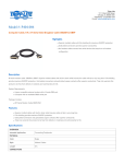
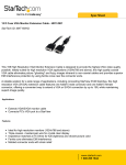
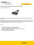
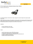
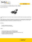
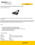
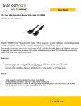
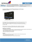
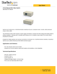
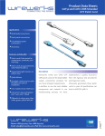
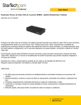
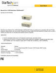
ST122UTPA.qxd
6/20/2006
2:18 PM
Page 1
Video Extender
Ethernet VGA Signal Extender for Distances up to 500 feet (150 m)
Ethernet VGA + Audio Signal Extender for Distances up to 500 feet (150 m)
ST121UTP (without Audio)
ST122UTPA (with Audio)
Instruction Manual
ST122UTPA shown
Actual product may vary from photo
ST122UTPA.qxd
6/20/2006
2:18 PM
Page 2
FCC Compliance Statement
This equipment has been tested and found to comply with the limits for a Class B digital
device, pursuant to part 15 of the FCC Rules. These limits are designed to provide
reasonable protection against harmful interference in a residential installation. This
equipment generates, uses and can radiate radio frequency energy and, if not installed
and used in accordance with the instructions, may cause harmful interference to radio
communications. However, there is no guarantee that interference will not occur in a
particular installation. If this equipment does cause harmful interference to radio or
television reception, which can be determined by turning the equipment off and on, the
user is encouraged to try to correct the interference by one or more of the following
measures:
• Reorient or relocate the receiving antenna.
• Increase the separation between the equipment and receiver.
• Connect the equipment into an outlet on a circuit different from that to which the
receiver is connected.
• Consult the dealer or an experienced radio/TV technician for help.
Use of Trademarks, Registered Trademarks, and
other Protected Names and Symbols
This manual may make reference to trademarks, registered trademarks, and other
protected names and/or symbols of third-party companies not related in any way to
StarTech.com Where they occur these references are for illustrative purposes only and
do not represent an endorsement of a product or service by StarTech.com, or an
endorsement of the product(s) to which this manual applies by the third-party company in
question. Regardless of any direct acknowledgement elsewhere in the body of this
document, StarTech.com hereby acknowledges that all trademarks, registered
trademarks, service marks, and other protected names and/or symbols contained in this
manual and related documents are the property of their respective holders.
ST122UTPA.qxd
6/20/2006
2:18 PM
Page i
Instruction Manual
Table of Contents
Introduction . . . . . . . . . . . . . . . . . . . . . . . . . . . . . . . . . . . . . . . . . . . . . . . . . . . . .1
Features . . . . . . . . . . . . . . . . . . . . . . . . . . . . . . . . . . . . . . . . . . . . . . . . . . . . . . . .1
Before You Begin . . . . . . . . . . . . . . . . . . . . . . . . . . . . . . . . . . . . . . . . . . . . . . . . .1
System Requirements . . . . . . . . . . . . . . . . . . . . . . . . . . . . . . . . . . . . . . . . . . .1
Contents . . . . . . . . . . . . . . . . . . . . . . . . . . . . . . . . . . . . . . . . . . . . . . . . . . . . .2
Connecting Your Signal Extender . . . . . . . . . . . . . . . . . . . . . . . . . . . . . . . . . . .2
Preparing Your Site . . . . . . . . . . . . . . . . . . . . . . . . . . . . . . . . . . . . . . . . . . . . .2
Installing the Local Unit . . . . . . . . . . . . . . . . . . . . . . . . . . . . . . . . . . . . . . . . . .3
Installing the Remote Unit . . . . . . . . . . . . . . . . . . . . . . . . . . . . . . . . . . . . . . . .4
Completing the Installation . . . . . . . . . . . . . . . . . . . . . . . . . . . . . . . . . . . . . . .4
Troubleshooting . . . . . . . . . . . . . . . . . . . . . . . . . . . . . . . . . . . . . . . . . . . . . . . . .5
Specifications . . . . . . . . . . . . . . . . . . . . . . . . . . . . . . . . . . . . . . . . . . . . . . . . . . .6
Accessory Products from StarTech.com . . . . . . . . . . . . . . . . . . . . . . . . . . . . .7
Technical Support . . . . . . . . . . . . . . . . . . . . . . . . . . . . . . . . . . . . . . . . . . . . . . . .8
Warranty Information . . . . . . . . . . . . . . . . . . . . . . . . . . . . . . . . . . . . . . . . . . . . .8
i
ST122UTPA.qxd
6/20/2006
2:18 PM
Page 1
Instruction Manual
Introduction
Thank you for purchasing a StarTech.com UTP signal extender. This product allows you
to extend the range of a signal source (usually a computer) up to 500 feet (150 meters)
using industry-standard Ethernet cabling. You can have two displays at both the local
and remote location, with little or no loss of image quality. Perfect for classrooms,
meeting areas, houses of worship, and any other application that would benefit from a
comprehensive multimedia sharing solution.
Features
• Reliably extends VGA (ST121UTP) or VGA and audio signals (ST122UTPA) to a
remote location up to 500 feet (150 meters) from a local source.
• Easy installation using standard Category 5 unshielded twisted pair (UTP) cabling.
• A completely hardware-based solution: no software or drivers required.
• Includes a unique Equalizer feature that optimizes image quality based on the cable
length.
• Built-in splitter allows a total of four displays from one VGA source: two local, and
two at the remote location.
Before You Begin
System Requirements
• 1 high-quality male-to-male HD-15 VGA cable (not provided)
StarTech.com part number: MXT101HQ
• ST122UTPA only: 1 high-quality male-to-male headphone audio cable (not provided)
StarTech.com part number: MU6MM
• Unshielded Category 5 twisted pair (UTP) straight-through Ethernet cable
terminated at each end with RJ-45 connectors (if using surface cabling)
OR
• Unshielded Category 5 twisted pair (UTP) straight-through Ethernet cable
terminated at each end in a wall-mounted outlet, with a standard Category 5 patch
cable, at both locations (if using premises cabling)
Do you need cables? Visit www.startech.com to find what you need and the name of a
StarTech.com dealer.
NOTE: The total length of cable between the Local and Remote Units cannot exceed 500
feet (150 meters), including patch cables (if used). Category 5e and 6 cabling is
compatible with this product and may improve performance.
NOTE: Long cable lengths between the Local and Remote Units may adversely affect
1
ST122UTPA.qxd
6/20/2006
2:18 PM
Page 2
Instruction Manual
image quality at high resolutions and refresh rates. If you need to run your remote
displays at high resolutions and frequencies, use as little Ethernet cabling between
locations as possible and avoid practices such as “coiling” unused cable in a ceiling or
behind the display.
Contents
This package should contain:
1
1
2
1
x
x
x
x
Local Unit (transmitter)
Remote Unit (receiver)
Power adapter
Instruction Manual
Connecting Your Signal Extender
This product is composed of two different units: the Local Unit and the Remote Unit. The
Local Unit takes the output from a VGA (and audio, if you purchased ST122UTPA) signal
source (usually a computer) and transmits it to the Remote Unit over Category 5
Ethernet cable. The remote displays (monitor, projector) connect to the Remote Unit
using standard VGA and headphone audio connections (if desired) and displays the
image from the local computer on the remote displays.
Preparing Your Site
Before you can install the the product, you need to prepare your site.
1: Determine where the local computer will be located and set up the computer.
2: Determine where the remote display(s) will be located and place/mount them
appropriately.
3a: If you are using surface cabling, ensure you have enough Category 5 unshielded
twisted pair (UTP) Ethernet cabling to connect the Local Unit to the Remote
Unit’s location, and that each end is terminated with a RJ-45 connector.
OR
3b: If you are using premises cabling, ensure that the Category 5 unshielded twisted pair
(UTP) Ethernet Cabling between the Local Unit and the Remote Unit has been
properly terminated in a wall outlet in each location and there is a
patch cable long enough to connect the Remote Unit and the Local Unit to
their respective outlets.
2
ST122UTPA.qxd
6/20/2006
2:18 PM
Page 3
Instruction Manual
Network
Video In
Power
Local Audio 1
Local Video Out (2)
Local Audio 2
Note: ST122UTPA shown: ST121UTP does not have audio support.
Installing the Local Unit
1: Place the Local Unit near the local computer.
2: Switch off the computer and disconnect any existing VGA and audio connections.
3: If desired, connect the data cable from the local computer display(s) to the video out
ports (marked with a monitor symbol) on the Local Unit. This will enable you to see
video locally while an image is transmitted to the remote display. You may choose to
connect up to two local displays, one for each video out port.
4: Connect a a male-to-male HD-15 VGA cable (not provided) to the VGA Out
port on the local computer. Connect the opposite end to the VGA IN port on the
Local Unit.
5. Connect a male-to-male headphone audio cable to the Speaker Out port on the local
computer. Connect the opposite end to the AUDIO IN port on the Local Unit.
(ST122UTPA only.)
6: Connect the Ethernet cable connection for Remote Unit to the Cat5 OUT RJ-45
connector on the Local Unit.
7: Connect the power adapter (provided) into an appropriate power source and plug the
opposite end into the power connector on the Local Unit. The POWER LED will
light.
8: If you wish to use local displays and speakers, connect them to the MONITOR 1/2 and
AUDIO 1/2 ports (for ST122UTPA) on the unit.
3
ST122UTPA.qxd
6/20/2006
2:18 PM
Page 4
Instruction Manual
Network
Signal Equalizer
Power
Remote Audio 1
Remote Audio 2
Remote Video Out (2)
Note: ST122UTPA shown: ST121UTP does not have audio support.
Installing the Remote Unit
1: Connect the Remote Unit to the Ethernet cable connection from the Local Unit,
marked Cat5 IN.
2: Connect the data cable from the display(s) to the opposite side of the Remote Unit,
marked MONITOR 3 and 4 (see above). You may choose to have either one or two
displays at the remote location connected to the Remote Unit.
3: Connect one or two sets of speakers to the AUDIO 3 and AUDIO 4 ports, if desired.
(ST122UTPA only.)
4: Connect the power adapter (provided) into an appropriate power source and plug the
opposite end into the power connector on the Remote Unit. The POWER LED will
light.
CAUTION: The Category 5 Ethernet cables that connect the Local and Remote Units
carry electrical current and should not be plugged in to other devices, as they may cause
damage. We strongly recommend marking the Ethernet cables you are using with this
product at both locations for easy identification.
Completing the Installation
1: Switch on the local computer and local
display(s) (if used).
2: Switch on the display(s) at the remote
location.
Signal Equalizer Settings
3: Verify that the remote display is properly
displaying the image from the local
computer connected to the Local Unit.
4: Use the Signal Equalizer to improve the image on the remote display(s) based on the
approximate length of Ethernet cable between the Local and Remote Units.
4
ST122UTPA.qxd
6/20/2006
2:18 PM
Page 5
Instruction Manual
Troubleshooting
The following section provides troubleshooting help. The solutions are arranged in the
order they should be attempted in most situations. If you continue to have difficulties
after attempting the solutions in this section, please contact StarTech.com technical
support using any of the methods on page 8.
Symptom: The remote displays are black or display a “no signal”
message.
Cause: The Remote Unit is not receiving a signal from the Local Unit.
Remedy: (1) Check that the display is receiving power and that all cables are connected.
(2) Check that the display is connected to the Remote Unit.
Symptom: The remote displays do not display an image when the local
computer wakes up from Standby Mode.
Remedy: Power the remote displays OFF and ON again.
Symptom: One or more remote displays is distorted, noisy, or displays a “signal error”
or similar error message.
Cause: The screen resolution and/or refresh rate on the local computer may be set too
high for the capabilities of the remote display.
Remedy: (1) Adjust the local computer to a lower resolution and refresh rate until the
remote display shows an image.
(2) Gradually increase the resolution and refresh rate on the local computer
until the remote displays ceases to display an image.
(3) Return the resolution and refresh rate on the local computer to the highest
resolution and refresh rate setting that displayed an image on the remote
display.
(4) Adjust the Signal Equalizer on the Remote Unit for best performance.
NOTE: If you are still unable to see an image at the remote location after trying the
above solutions, it is recommended that you verify the Ethernet cable installation to the
remote display before calling technical support. This can be used using a standard cable
tester. If you do not have a cable tester, contact a local computer service or wiring
professional.
5
ST122UTPA.qxd
6/20/2006
2:18 PM
Page 6
Instruction Manual
Specifications
Maximum Resolution
1024 x 768 (at maximum Ethernet cable length)
Actual maximum resolution varies by Ethernet cable length
Maximum Range
500 feet (150 meters)
Ethernet Cabling Type
Straight-through Unshielded Twisted Pair (UTP) Cat. 5+
Connectors
Local Unit
1 x HD-15 male VGA (video in)
1 x 3.5mm phono female (audio in) ST122UTPA only
1 x RJ-45
2 x HD-15 female VGA (video out)
2 x 3.5mm phono female (audio out) ST122UTPA only
1 x Power
Remote Unit
2 x HD-15 female (video out)
2 x 3.5mm phono female (audio out) ST122UTPA only
1 x RJ-45
1 x Power
LED Indicators
1 x Power (green)
1 x Activity (yellow)
Power Adapter
2 x 9v, 600mA, center positive (one per Unit)
6
ST122UTPA.qxd
6/20/2006
2:18 PM
Page 7
Instruction Manual
Accessory Products from StarTech.com
Contact your local StarTech.com dealer or visit www.startech.com for cables or other
accessories that will help you get the best performance out of your new product.
25 ft Blue Snagless Category 5e (350 MHz) UTP Patch Cable
RJ45PATCH25
35 ft Blue Snagless Category 5e (350 MHz) UTP Patch Cable
RJ45PATCH35
50 ft Blue Snagless Category 5e (350 MHz) UTP Patch Cable
RJ45PATCH50
75 ft Blue Snagless Category 5e (350 MHz) UTP Patch Cable
RJ45PATCH75
100 ft Blue Snagless Category 5e (350 MHz) UTP Patch Cable
RJ45PATCH100
(other colors and lengths available)
6 ft. Coax SVGA Monitor Cable HDDB15M/M
MXT101MMHQ
25 ft. Coax SVGA Monitor Cable HDDB15M/M
MXT101MMHQ25
50 ft. Coax SVGA Monitor Cable HDDB15M/M
MXT101MMHQ50
15 ft. Coax SVGA Monitor Extension Cable HDDB15M/F
MXT105HQ
15 ft. Coax SVGA Monitor Cable HDDB15M/M
MXT105MMHQ
7
ST122UTPA.qxd
6/20/2006
2:18 PM
Page 8
Instruction Manual
Technical Support
StarTech.com’s lifetime technical support is an integral part of our commitment to provide
industry-leading solutions. If you ever need help with your product, visit our Web site to
access our comprehensive selection of online tools, documentation, and downloads.
USA/Canada: www.startech.com/support
UK/Ireland/Europe: uk.startech.com/support
Warranty Information
This product is backed by a one-year warranty. In addition, StarTech.com warrants its
products against defects in materials and workmanship for the periods noted, following
the initial date of purchase. During this period, the products may be returned for repair, or
replacement with equivalent products at our discretion. The warranty covers parts and
labor costs only. StarTech.com does not warrant its products from defects or damages
arising from misuse, abuse, alteration, or normal wear and tear.
Limitation of Liability
In no event shall the liability of StarTech.com Ltd. and StarTech.com USA LLP (or their
officers, directors, employees or agents) for any damages (whether direct or indirect,
special, punitive, incidental, consequential, or otherwise), loss of profits, loss of business,
or any pecuniary loss, arising out of or related to the use of the product exceed the
actual price paid for the product.
Some states do not allow the exclusion or limitation of incidental or consequential
damages. If such laws apply, the limitations or exclusions contained in this statement
may not apply to you.
8
ST122UTPA.qxd
6/20/2006
2:18 PM
Revised: 20 September 2005 (Rev. A)
Page 9