1
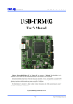
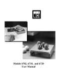
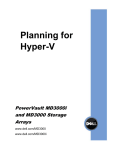
Personnel safety and machine protection
Risk category according to EN 954-1
Classification of a machine into categories to EN 954-1
F-
Frequency and/or duration of the risk exposure
F1 Rare to frequent and/or short duration of exposure
F1 Frequent to sustained and/or longduration of exposure
P-
Options for risk avoidance
(Generally referred to the speed and frequency at which the
dangerous components moves and to the clearance from
the dangerous component).
P1 Possible under certain conditions
P2 Hardly possible
Pursuant to the Machinery Directive 89/393/EEC, every machine must
comply with the relevant directives and standards. Measures must be taken to
keep the risk to persons below a tolerable extent.
In the first step, the project planner performs a risk evaluation to
EN 1050 "Risk Assessment". This must take into consideration the machine's
ambient conditions for instance. Any overall risk must then be assessed. This risk
assessment must be conducted in such a form as to allow documentation of the
procedure and the results achieved. The risks, dangers and possible technical
measures to reduce risks and dangers must be stipulated in this risk assessment.
After stipulating the extent of the risk, the category on the basis of which the
safety circuits are to be designed is determined with the aid of EN 954-1 “SafetyRelated Components of Controls”.
7
Categories
B
This determined category defines the technical requirements applicable to the
design of the safety equipment.
1
2
3
4
S1
There are five categories (B, 1, 2, 3 and 4), whereby B (standing for basic category) defines the lowest risk and, thus, also the minimum requirements applicable to
the controller.
P1
F1
P2
S2
Possible selection of categories pursuant to EN 954-1
Starting point for the risk assessment of the safety-related component of the
controller.
S-
Serious injuries
S1
Slight (normally reversible) injuries,
S2
Serious (normally irreversible) injuries,
including death
P1
F2
P2
B1-4 Categories for safety-related components of controls
●
●
Preferred category
Possible category requiring additional measures
Disproportionately extensive measures by comparison
with the risk
Safety
category 1
Summary of requirements
System behaviour 2
B
The safety-related components of controls and/or their protection
devices and their components must be designed, constructed,
selected, assembled and combined in compliance with the
applicable standards, such that they can withstand the anticipated
influences.
The occurrence of a fault may lead
to loss of the safety function.
1
The requirements of B must be complied with.
Time-proven components and time-proven safety principles
must be applied.
The occurrence of a fault may lead
to loss of the safety function but the
probability of occurrence is less than
in category B.
2
The requirements of B and the use of the time-proven safety principles
must be complied with.
The safety function must be checked at appropriate intervals
by the machine control.
•
The occurrence of a fault may lead
to loss of the safety function between
the inspection intervals.
•
The loss of the safety function is
detected by the check/inspection.
If the single fault occurs, the safety
function is always retained.
3
4
The requirements of B and the use of the time-proven safety principles
must be complied with.
Safety related components must be designed such that:
• a single fault in any of these components does not lead to loss
of the safety function and
• the individual fault is detected, wherever feasible in an
appropriate manner.
The requirements of B and the use of the time-proven safety principles
must be complied with.
Safety related components must be designed such that:
• a single fault in any of these components does not lead to loss
of the safety function and
• the individual fault is detected at or before the next requirement
applicable to the safety function or, if this is not possible
an accumulation offaults may then not lead to loss of the
safety function.
Principles for
achieving safety
Predominantly characterised
by selection of componentsl
•
•
•
•
•
Certain faults but not all faults are
detected.
An accumulation of undetected faults
may lead to loss of the safety function.
If the faults occur, the safety function
is always retained.
The faults are detected in good time to
prevent loss of the safety function
Predominantly
characterised
by the structure
This mandatory classification runs likes a red thread from selection of the smallest limit switch through to the overall concept of the entire
machine, whereby it is necessary to grapple with the permanent conflict between what is technically feasible and what is permitted on the basis
of “pure theory”.
Thus: Depending on application, not every technically feasible safety category is also permitted. For instance, in the case of contactless
protection devices (light barriers etc.) only categories 2 or 4 are permitted. By contrast, in the case of tread mats, categories B to 4 can be used,
depending on risk assessment, provided these categories can be reached at all owing to the design.
The 2-hand control C575 would technically also comply with the lower categories but it cannot be connected in categories 1-3.
1 The categories are not intended to be applied in any specific order or hierarchical arrangements with respect to the technical-safety requirements.
2 The risk assessment will indicate whether full or partial loss of the safety function(s) as the result of fault is acceptable.
CTi Automation - Phone: 800.894.0412 - Fax: 208.368.0415 - Web: www.ctiautomation.net - Email: [email protected]
Personnel and machine protection
Classification of a machine into
categories to EN 954-1
Pursuant to the Machinery Directive 89/393/EEC, every machine must comply with the relevant Directives
and Standards. Measures must be taken to keep the
risk to persons below a tolerable extent.
In the first step, the project planner performs a risk
evaluation to EN 1050 “Risk Assessment”. This must
take into consideration the machine’s ambient conditions for instance. Any overall risk must then be
assessed. This risk assessment must be conducted
in such a form as to allow documentation of the procedure and the results achieved. The risks, dangers
and possible technical measures to reduce risks and
dangers must be stipulated in this risk assessment.
After stipulating the extent of the risk, the category
on the basis of which the safety circuits are to be
designed is determined with the aid of EN 954-1
“Safety-Related Components of Controls”.
This determined category defines the technical
requirements applicable to the design of the safety
equipment. There are five categories (B, 1, 2, 3 and 4)
whereby B (standing for basic category) defines the
lowest risk and, thus, also the minimum requirements
applicable to the controller.
Possible selection of categories pursuant to
EN 954-1
Starting point for risk assessment of the safety-related components of the control.
Description
Scope of application
Potential risks and hazards posed by a machine must
be eliminated as quickly as possible in the event of
danger.
For dangerous movements, the safe state is generally standstill. All safety switching devices of Series
C 570 switch to de-energised state, i.e. standstill for
drives, in the event of danger or fault. Standard EN
60204 demands that every machine must feature the
Stop function of category 0.
Stop functions of categories 1 and/or 2 must be provided if necessary for technical-safety and/or technical-function requirements of the machine. Category-0
and category-1 stops must be operable independently of the operating mode, and a category-0 stop
must have priority.
There are three categories of stop function:
Category 0:
Shut-down by immediate switch-off of the energy
supply to the machine drives.
Category 1:
Controlled shut-down, whereby the energy supply
to the machine drive is retained in order to achieve
shut-down and the energy supply is only interrupted
when shut-down has been reached.
Category 2:
A controlled shut-down in which the energy supply to
the machine drive is retained.
EMERGENCY-STOP
EMERGENCY-STOP devices must have priority
over all other functions. The energy supplied to the
machine drives which may cause dangerous states
must be switched off as quickly as possible without
further risks or dangers. Resetting of the drives may
not trigger a restart. The EMERGENCY-STOP must
act either as a stop of category 0 or as a stop of
category 1.
Low Voltage Products & Systems
ABB Inc. • 888-385-1221 • www.abb-control.com
The basic device of the 570 Series of safety switching devices can be used for EMERGENCY-STOP
applications up to maximum category 4 to EN 954-1.
Depending on external wiring and cable routing of
the sensors, category 3 resp. 4
to EN 954-1 must be reached.
Safety door monitoring
Pursuant to EN 1088, a distinction is made between
interlocked, separating protective devices and interlocked, separating protective devices with follower.
Here as well, the safety switching devices are used
for EMERGENCY-STOP applications. Controls up to
category 4 to EN 954-1 are possible.
Presses and punches
The two-hand control C 575 is a device on which the
operator must use both hands simultaneously, thus
protecting him against risks and dangers.
The overtravel monitor C 578 is used on linear-driven
presses (e.g. hydraulic, pneumatic and
spindle presses) in accordance with VBG7n52.
It checks for the following only once during the
test stroke:
- Correct connection of the operating controls
- External cable discontinuity
- Possible failure of the components to be
monitored cyclically
The overtravel monitor can be used only in conjunction with a two-hand control. The press controllers
and overtravel monitors are suitable for installation in
controls for eccentric, hydraulic and spindle presses.
They can be used up to category 4 to EN 954-1. Type
III C to DIN 574 is possible specifically for presses.
Device construction
The safety switching device C 570 operates internally
with several contactor relays. The contacts of the
relays comply with the requirement in respect of positively driven operation to ZH 1/457, Edition 2, 1978.
This means that NO contact and NC contact may not
be closed simultaneously.
Safety relays with positively driven contacts are used
in the newly developed safety switching devices C
571-C 574, C 576, C 577 , the contact expansion C
579 and on the press controllers
C 575 and C 578. This series of devices is characterised by an extremely narrow design
(22.5mm and 45 mm). Approvals and
test certificates, conventional on the market, have
been issued by BG, SUVA, UL and CSA.
The function of the internal contactor relays/relays
is monitored in a redundant circuit. In the event of
failure of a relay, the safety switching device always
switches to de-energised state. The fault is detected
and the safety switching device can no longer be
switched on. Using normally closed contacts and
normally open contacts for the same function complies with the requirement in respect
of diversity.
Enable contacts (FK)
The safety-related function must be controlled via
safe output contacts, the so-called Enable contacts.
Enable contacts are always normally open contacts
and switch off without delay.
Signalling contacts (MK)
Normally open contacts and normally closed contacts which may not perform safety-related functions
are used as the signalling contact.
An Enable contact may also be used as a
signalling contact.
Delayed Enable contacts
Drives which have a long overtravel must be
decelerated in the event of danger. For this purpose,
the energy supply must be maintained for electrical
braking (stop category 1 to EN 60 204-1). The safety
switching device C 574 also feature OFF-delayed
Enable contacts, besides undelayed Enable contacts.
Delay times of 0.5 to 30 s are available.
The sealable cover cap C 560.10 (see Selection data
and Ordering details, Accessories) can be fitted onto
C 574, C 6702 to protect against unauthorised adjustment of the set delay time.
Contact expansion
If the Enable contacts of the basic device do not
suffice, positively driven contactors (e.g. B6, B7)
may be used for contact expansion. One solution for
increasing the number of Enable contacts, which is
both simple to use and space-saving,
is the expansion unit C 579 (only 22.5mm wide).
The expansion unit C 579 provides 4 additional Enable contacts.
Expansion unit C 579
Expansion unit C 579 may not be operated separately in safety-related circuits but must be combined
with a safety switching device C 57x. One Enable
contact of the basic device is required for connection
of an expansion unit. The category of a control with
expansion units corresponds to the category of the
basic device.
Mounting
Snap-on mounting on 35mm top-hat rail to
EN 50 022. Screw mounting of the safety switching
devices C 57x can be implemented with two additional plug-in tabs C 560.20 (see Selection data and
Ordering details, Accessories).
User Manual
A User Manual with a device description, connection diagrams and application information in several
languages is enclosed with every safety switching
devices of Series C 570 and C 67xx.
“Safety Engineering” Application Manual
You can find further information in the “Safety
Engineering” Application Manual. It provides you with
the required information on the relevant safety standards and project planning information.
The entire range of components used for safety applications is explained in this Manual, from the sensor
(Emergency-Stop command devices and position
switches), through evaluation units (safety switching
devices C 57x and fail-safe control
AC 31 S) to the actuator (e.g. contactor for switching
motors). All these components must be selected correctly in order to meet the requirements applicable to
modern safety facilities.
Please order the “Safety Engineering” Application
Manual
1SAC 103 201 H 0101 German
1SAC 103 201 H 0201 English
7.55
1SXU 000 023 C0201
CTi Automation - Phone: 800.894.0412 - Fax: 208.368.0415 - Web: www.ctiautomation.net - Email: [email protected]
7