1
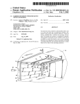
US 6,644,098 B2
11
12
the steps of: de?ning a sequence of desired temperature
tively be an improved sensing device such as the one
described in conjunction With FIG. 6. Further, in an
values; and adjusting the temperature of the detector accord
improved method of making the sensing device 11 shoWn in
ing to the de?ned sequence.
In features of this method, the step of adjusting the
temperature includes, for each desired temperature value in
the sequence, the steps of determining the next desired
temperature value in the sequence, controlling the tempera
ture of the detector to effect the desired temperature value,
monitoring the temperature of the detector to determine if
the desired temperature value has been reached, and repeat
FIG. 1 or the improved sensing device 111 shoWn in FIG. 6,
an uncoated cathode Wire 24 may be inserted into the
uncoated anode coil 26, With the combination then being
coated With one or tWo coatings of the ceramic material
described previously. The un?red anode/cathode assembly
may then be mounted Within the housing, Which may be a
standard TO-5 can. The sensing device 11 is then energiZed,
thus ?ring and biasing the sensing device 11 simultaneously
ing the controlling and monitoring steps until the desired
in a relatively short period of time. It has been found that
temperature value has been reached; the method includes the
step of storing the desired temperature values in a memory;
and the sequence of desired temperature values is selected to
create a ramp function of temperature versus time.
satisfactory performance in terms of sensitivity and repeat
ability may be achieved in as little as thirty minutes, thus
15
As shoWn, the sensing device 11 may be electrically
connected to the rest of the primary detection circuit 10 via
its anode contacts 28 and its cathode contact 30. As is Well
knoWn in the art, When thus installed in a suitable circuit,
such as the primary detection circuit 10 of the present
invention, a bias current is generated at the cathode contact
30. The magnitude of the bias current is dependent on the
BRIEF DESCRIPTION OF THE DRAWINGS
Further features, embodiments, and advantages of the
present invention Will become apparent from the folloWing
detailed description With reference to the draWings, Wherein:
FIG. 1 is a detailed diagrammatic vieW of a prior art
sensing device for use in various embodiments of the heated
average potential difference betWeen the voltage drop across
the anode coil and the cathode voltage, the temperature of
electrode refrigerant detectors of the present invention;
FIG. 2 is a schematic diagram of a ?rst preferred embodi
ment of a heated electrode refrigerant detector according to
reducing assembly time dramatically.
25
the sensing device 11, the length of time the sensing device
11 has been operating, the ambient concentration of halo
the present invention;
genated molecules surrounding the sensing device 11, and
FIG. 3 is a schematic diagram of a second preferred
embodiment of the heated electrode refrigerant detector of
the history of the sensing device’s exposure to halogenated
molecules during all of its previous usage. Thus, after
“burning in” the sensing device 11, subsequent exposure of
the sensing device 11 to reactive gases like halogen, While
the present invention;
FIG. 4 is a schematic diagram of a third preferred embodi
ment of the heated electrode refrigerant detector of the
the device 11 is being heated, causes ions to How from the
anode 26 to the cathode 24, causing an increase in the bias
present invention;
current. This characteristic may therefore be used as an
FIG. 5 is a schematic diagram of a variation of the third
indicator of the presence or absence of halogenated mol
ecules at the sensing device 11.
preferred embodiment of the heated electrode refrigerant
detector of FIG. 4; and
The battery poWer supply 12 may be any readily available
FIG. 6 is a detailed diagrammatic vieW of an improved
sensing device suitable for use in the primary detection
circuits of FIGS. 2—4.
battery device Which in a typical embodiment may supply an
unregulated voltage in the range of 4 to 8 VDC. The sWitch
DETAILED DESCRIPTION OF THE
PREFERRED EMBODIMENTS
propagating a current through the anode coil 26 of the
Referring noW to the draWings, in Which like numerals
represent like components throughout the several vieWs, an
may be a transistor or other suitable device capable of
sensing device 11 at a suitable input frequency and duty
cycle, Which as described herein may be 20 kHZ and less
than 10% respectively. At its typical operating temperature
45
of 600° C. to 1000° C., the anode coil 26 has an effective
improved heated electrode refrigerant detector 5 having one
resistance of approximately 1 ohm. Thus, during the brief
or more control loop, in accordance With the preferred
embodiments of the present invention, Will noW be shoWn
and described. FIGS. 2—4 are schematic diagrams of ?rst,
portion of each cycle When the sWitch 15 is “on,” a current
second and third preferred embodiments of the improved
heated electrode refrigerant detector 5 of the present inven
capacitor 32 and an inductor 34 are provided on the poWer
is generated through the anode coil 26 of approximately 4A
to 8A. Because of the large magnitude of this current, a ?rst
supply side of the sensing device 11 to ?lter the current
spikes of generally short duration (typically 1.5 psec to 4.0
psec) Which Would otherWise present signi?cant noise on the
tion.
In each preferred embodiment, the heated electrode
refrigerant detector 5 of the present invention comprises a
primary detection circuit 10, a post-processor 18 for post
poWer supply.
55
The current source 14 provides a ?xed current of much
processing one or more signals, a leak detection indicator
smaller magnitude than that Which is generated through the
and alarm 20 and at least one control loop 22. The primary
detection circuit 10 includes a sensing device 11, a battery
anode coil 26 While the sWitch 15 is on. In a suitable
embodiment, the current source may supply a current of 10
poWer supply 12, a current source 14, a sWitch 15 for
bypassing the current source 14, a modulator 16 for modu
mA. During that portion of each cycle When the sWitch 15
is “off,”a current of approximately 10 mA is thus generated
through the anode coil 26. The voltage drop across the anode
coil 26 While the sWitch is off is directly proportional to the
lating the sWitch 15 according to a desired duty cycle
determined by one or more of the control loops 22, and a
number of basic circuitry components, including ?rst and
second capacitors 32, 38, a resistor 36 and an inductor 34.
The sensing device 11 may be any conventional heated
electrode refrigerant sensing device such as the one previ
ously described and illustrated in FIG. 1, or may alterna
effective resistance of the anode coil 26. Because this
resistance is a function of the temperature of the coil 26,
65
Which increases in approximately linear fashion, and
because the current through the coil 26 is constant While the
sWitch 15 is “off,” the magnitude of the voltage drop across