1
DRAFT
General
A new pressure period counter (PPC) used with a Paroscientific Digiquartz Pressure Sensor provides
higher resolution temperature-compensated pressure data than has previously been available for deepocean observations. Pressure resolution of < 30 ppb full scale at 1 Hz has been realized. System data
are stored on a compact flash card (maximum 1 GB) and can be downloaded on-site. Each system
comprises 1 to 9 PPC channels and sensors, a real-time clock (RTC), a serial-to-compact-flash logger
(SCF), and batteries.
History
An investigation began in late 2003 to determine whether a period-counter circuit could be designed with
improved resolution, noise, and power consumption, which would be of significant benefit to the earth and
ocean science community. The PPC results from this work. Several prototype units using a preliminary
algorithm were deployed in September 2004 for an IODP CORK borehole observatory program, with the
following operating properties:
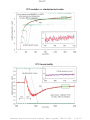
Pressure period measurement noise: < 10 ppb @ 800 ms integration time (1 Hz sampling)
Relative pressure resolution: < 100 ppb full scale @ 800 ms integration time
Temperature period measurement noise: < 1 ppm @ 400 ms integration time
Absolute pressure accuracy (temperature-compensated): < 1 ppm full scale
Average power dissipation: < 30 mW @ 4 channels, 1 minute sampling
Note: 100 ppb resolution equates to 0. 4 mm head for a 4000 m sensor
Current status
Recent algorithm improvements (see plots overleaf) provide the following performance:
PPC features:
Pressure period measurement noise: < 3 ppb @ 800 ms integration time
Relative pressure resolution: < 30 ppb p-p full scale @ 800 ms integration time
Power dissipation, per channel, during measurement cycle: 42 mW [ 0 mW when sleeping]
RTC features:
Maximum sample rate: 1 Hz
Clock accuracy: ~ 4 ppm (2 min/yr)
Power dissipation (sleeping): < 1 mW
Power (measurement cycle): < 5 mW
SCF (Minerva logger) features:
Communications hardware: RS422 / RS232
Communication rates: 4.8 to 230.4 kBaud
Download protocols (bytes/packet): custom (512), Xmodem (128), streaming
Further information available:
John R. Bennest
ph/fax: 250.494.5145
Bennest Enterprises Ltd.
PO Box 1092 (mail)
12438 Victoria Road South
SUMMERLAND, B.C. CANADA
V0H 1Z0
Bennest Precision Period Counter (PPC) system
2007/11/09
1 of 15
DRAFT
Bennest Precision Period Counter (PPC) system
2007/11/09
2 of 15
DRAFT
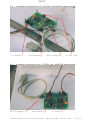
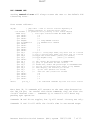
Fig. 1 A minimum system (top/front view) : RTC/PPC card (with RS232 adapter attached)
to sensor
from battery
RS232 adapter
VC-TXO trim
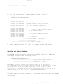
Fig. 2 A minimum system (top/rear view) : RTC/PPC card (with RS232 adapter attached)
RS232 adapter
from battery
to sensor
Bennest Precision Period Counter (PPC) system
2007/11/09
3 of 15
DRAFT
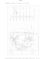
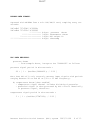
MECHANICAL OUTLINES (all dimensions in inches) :
Bennest Precision Period Counter (PPC) system
2007/11/09
4 of 15
DRAFT
QUICK-START OPERATION [with RS232 dongle attached]:
1.
connect sensor (pinouts listed on last page)
2.
connect RS232 plug to computer serial port
run Hyperterminal or similar terminal program
- set up for 8N1 19200 baud
3.
connect PPC power (either battery or AC adapter)
4.
observe 1 Hz data sentences:
.
.
$7h14070908000237$047226250701AF 7D6E6B2A
$7h14070908000238$051213250701B0 7D6E011E
$7h14070908000239$053211250701B1 7D6E3840
^^^^^^^^---4-byte averaged thermometer data
^^^^^^^^----------- 4-byte binary timestamp
^^^--------------------10-bit supply voltage
^^^-----------------------10-bit battery current
YYYYMMDDHHMMSS --------------------------ascii timestamp
^^^-----------------------------------------software version ID
.
.
5.
see file “RTCboot.txt” for more...
6.
disconnect power when done...
POWER OPTIONS:
PPC consumes ~ 60 mW in continuous operation [single channel].
The PPC is designed to operate from either a 6 volt SLA battery or a
7.2 volt lithium battery connected at the battery socket, but 9-volt
or nominal 12-volt batteries are also OK (see below). Overcurrent
protection PTC may trip if battery voltage exceeds the ~ 15 volt
threshold of a protection zener.
IF AC power is available, a small 12 VDC wall-wart may be connected
at the flying-lead from the RS232 adapter. This power input has
polarity, over-voltage and over-current limiting, and will provide
the PPC with a regulated nominal 7.8 volts, diode-summed with
whatever battery is connected. Note that if battery voltage is
greater than 7.8 volts, battery will power the card, whether or not
the AUX POWER input is active.
Bennest Precision Period Counter (PPC) system
2007/11/09
5 of 15
DRAFT
INTERMITTENT operation:
In isolated deployments, operating from a battery pack, the power
consumption of the system will likely determine the sample rate, in a
complex tradeoff between battery life, sample rate and integration
[measurement] duration. Longer integration times provide quieter
measurements at the expense of power consumption. See the MLCORK
operating manual for details of the programmable features of the
system.
1 Hz [NEPTUNE] operation:
[FEATURE ADDED 2007 09 01]
When ample power is available, the PPC unit can operate at a 1 Hz
sample rate, with fixed PPC parameters that implement a best-possible
measurement of the pressure input signal. In NEPTUNE mode, the PPC
channels are powered continuously, and every input signal edge is
utilized for lowest possible noise.
NEPTUNE mode is available to the user in several ways:
Setting the NEPTUNE control byte in the RTC EEROM to 00 hex will
force the unit into NEPTUNE mode independent of input voltage.
Similarly, setting the NEPTUNE control byte to FF hex will force the
unit into intermittent mode independent of input voltage.
IF the NEPTUNE control byte in the RTC EEROM is set to ~ 8C hex, then
the unit will automatically switch into NEPTUNE mode [and back to
INTERMITTENT mode] depending on the apparent input voltage. The RTC
monitors its available input voltage [diode-summed as described
above]; If the voltage exceeds the threshold established by the ~8C
control byte, then NEPTUNE mode is enabled. If the voltage
subsequently drops below the threshold, the unit will revert to
INTERMITTENT mode.
In an attempt to minimize nuisance switching, this switchover will
only occur after two or three successive voltage measurements have
met the above requirements. In NEPTUNE mode, the RTC is testing the
voltage once per second, so reversion to INTERMITTENT mode will occur
within 2 or 3 seconds. Once in INTERMITTENT mode, however, the RTC
is only testing at the programmed sample rate. If, for instance,
this has been set to 30 seconds, the NEPTUNE switchover may not occur
for 60 or 90 seconds.
Bennest Precision Period Counter (PPC) system
2007/11/09
6 of 15
DRAFT
RTC COMMAND SET:
sending control-C <cr> will always return the user to the default RTC
timestring state.
From recent software:
CRjump
; jump table - send to various routines depending on
; leading character in received serial string
clrf PCLATH ; to guarantee we're pointing to this lowest subpage
addwf PCL,f
;
note input characters MUST BE UPPER CASE !
goto CRexit
; A
goto CRexit
; B
goto CRexit
; C
goto dumpEE
; D Dump EEPROM contents
goto writeEEblock
; E EEPROM write command
goto CRexit
; F
goto CRexit
; G
goto CRexit
; H
goto CRexit
; I
goto CRexit
; J
goto CR_K
; K sync to rising edge IO1HZ, may cause loss of 1 second
goto CR_L
; L sync to falling edge IO1HZ, may cause loss of 1 second
goto CR_M
; M toggle 1Hz driver-enable [send !Q to disable]
goto CR_N
; N toggle NepEnbl flag
[send !Q to disable]
goto CRexit
; O
goto CR_P
; P PPC, enable PPC passthrough in NORMAL mode
goto CR_Q
; Q Quit, ie power-down the PPC circuits
goto CR_R
; R Resume PPC, enable PPC passthrough in CALIBRATE mode
goto CR_S
; S Set the clock registers with values in top EEPROM
goto CR_T
; T Time display, one sentence per second
goto CR_U
; U
Up the time (advance one second)
goto CR_V
; V
down the time (retard one second0
goto CRexit
; W
goto CRexit
; X
goto CRexit
; Y
goto CRexit
; Z
;
CRexit
goto sp_1
; all undefined commands hop back into outer routine
Note that !K, !L commands will execute at the next edge detected on
the 1HZ_I/O pin. Be careful with these commands; they can alter the
clock’s internal time... Commands !Q or control-C will abort any
pending sync operation.
Commands !M and !N are toggles, but !Q will cancel. Factory use only.
Commands !U and !V will shift the clock’s time in one-second steps.
Bennest Precision Period Counter (PPC) system
2007/11/09
7 of 15
DRAFT
VIEWING RTC EEROM CONTENTS:
Various control bytes stored in EEROM can be viewed and edited.
A.
To view these bytes, send command string
“!D<cr>”:
(default contents shown)
E0
E1
E2
E3
E4
E5
E6
E7
E8
E9
EA
EB
EC
ED
EE
EF
2036 ;
7320 ;
4544 ; these eight lines (64 bytes total)
6F63 ; are NOT used for control, and can
7761 ; be freely redefined by the user,
2061 ; e.g. for instrument ID purposes
722D ;
642E ;
F9FF
; # of PPCs, sample interval, delays
0000
; PPC presence table
6852
3730
; see user manual for details
FFFF
FFFF
3200
; start-time
4B00
; rate control
^^------ non-functional – factory ID
^^----------- control byte
^------------------------ line number ( in Hex!! )
B.
6C6F
3420
4E4F
2062
6B20
7265
7265
6465
0102
0900
0000
5443
3930
FFFF
1407
0000
7765
6279
5420
7920
736F
2E41
2075
6669
50FF
0000
0000
2032
370D
FFFF
0907
0000
7374
7465
5553
636C
6674
4C4C
7365
6E65
F380
0000
2437
3030
0AFF
FFFF
173B
9600
send command string “!T <cr>” to resume normal operation
CHANGING RTC EEROM CONTENTS:
All EEROM contents can be overwritten, EIGHT BYTES AT A TIME, by
sending a string in the following form:
“
!Enkkkkkkkkkkkkkkkk<cr>
”
^^^^^^^^^^^^^^^^^^^------------ eight HEX bytes [data payload]
^------------------------------- line number ( in Hex!! )
^^--------------------------------- command header
IMPORTANT : overwrite command executes upon reception of trailing <cr>
All eight data bytes (16 characters) MUST be entered; if data string is shorter
than eight bytes, trailing garbage characters will be written to EEROM.
Helpful hint: it is OK to send a couple of extra characters at the end of the
command line prior to the <cr>, i.e. “!E8010250FFF380F9FF00<cr>”
See user manual for full details.
operations.
See below for equivalent PPC EEROM
Bennest Precision Period Counter (PPC) system
2007/11/09
8 of 15
DRAFT
BINARY DATA FORMAT:
Captured with MLTERM from a solo RTC/PPC/T card, sampling every two
seconds:
24fca8b2 757d79b5 3fffff8c
24fca8b4 757d7956 3fffff95
^^^^^^^^--^^^^^^-----------^^-----------------^^^^^^^^---------------------
4-byte pressure datum
3-byte thermometer datum
1-byte RTC unique ID
4-byte timestamp
PPC DATA DECODING:
pressure datum
- from example above, interpret the “3FFFFF95” as follows:
pressure signal period in microseconds =
20 * [ 1 + (hex2dec{3FFFFF95}) / 2^32 ]
Note that PPC will only correctly measure input signals with periods
ranging between 20 us and 40 us (50 to 25 kHz frequency).
b) temperature datum [when enabled]
- temperature signal channel includes divide-by-4 prescaler
- prescaled signal is then processed by PPC circuit identically
to pressure signal, therefore:
temperature signal period in microseconds =
5 * [ 1 + (hex2dec{375B7169}) / 2^32 ]
Bennest Precision Period Counter (PPC) system
2007/11/09
9 of 15
DRAFT
PPC ABSOLUTE CALIBRATION:
Unit is factory-adjusted to be within ~ 0.1 ppm at ~ 2 degC.
User can adjust the 12.8 MHz reference VC-TXO if desired:
- substitute a known signal frequency for pressure input
o must be AC-coupled !
o 3 to 5 V p-p amplitude, square-wave preferred
- make adjustments with the blue multi-turn trimpot located near
the center of the top edge of the card (see Fig. 1)
SENSOR POWER PROTECTION:
PPC provides ~ 6.8 volts to sensor. Sensor current is sampled during
its power-up, and if it exceeds a (programmable) threshold, nominally
~ 6 mA, the sensor power will be disconnected. Data is reported as
FFFFFFFF hex to signal this condition.
KNOWN BUGS/NUISANCES [PPC ascii-output mode only]:
IF signal is absent on pressure input, data output ceases.
With temperature measurement enabled, then IF pressure signal
present, but no temperature signal, temperature signal is reported as
all-zeros.
COMMAND STRING DEFINITIONS: (see next page for explanations...)
!PPD<cr>
-
Dump the EEROM contents
!PPEnkkk..kkk<cr>
-
Enter revised EEROM data at line n
Bennest Precision Period Counter (PPC) system
2007/11/09
10 of 15
DRAFT
VIEWING PPC EEROM CONTENTS:
Various control bytes stored in EEROM can be viewed and edited.
A.
To view these bytes, send command string
“!PPD<cr>”:
(default contents shown)
E0
E1
E2
E3
E4
E5
E6
E7
E8
E9
EA
EB
EC
ED
EE
EF
6C6F
3420
4E4F
2062
206D
2E41
2075
6669
2863
6A2E
6573
6F6C
616C
0D0A
E70F
323C
7765
6279
5420
7920
6163
4C4C
7365
6E65
2932
722E
740D
6F50
2040
FFFF
1A58
2105
7374
7465
5553
7468
6869
2061
722D
642E
3030
6265
0A0A
7063
2032
FFFF
E5C8
3200
2036
7320
4544
6973
6E65
7265
6465
FFFF
3620
6E6E
3153
2063
3043
FFFF
0A33
00FF
;
;
;
;
;
;
;
;
)
)
)
)
)
)
;
;
these eight lines (64 bytes total)
are NOT used for control, and can
be freely redefined by the user,
e.g. for instrument ID purposes
Ascii strings sent at powerup
for software ID purposes
** DO NOT CHANGE THESE BYTES !! **
timing control bytes (see below)
^------------------------- line number ( in Hex!! )
B. send command string “!PPS<cr>” to resume normal operation
CHANGING PPC EEROM CONTENTS:
All EEROM contents can be overwritten, EIGHT BYTES AT A TIME, by
sending a string in the following form:
“
!PPEnkkkkkkkkkkkkkkkk<cr>
”
^^^^^^^^^^^^^^^^^^^------------ eight HEX bytes [data payload]
^------------------------------- line number ( in Hex!! )
^^^^--------------------------------- command header
IMPORTANT : overwrite command executes upon reception of trailing <cr>
All eight data bytes (16 characters) MUST be entered; if data string is shorter
than eight bytes, trailing garbage characters will be written to EEROM.
Helpful hint: it is OK to send a couple of extra characters at the end of the
command line prior to the <cr>, i.e. “!PPEF64646405320000FF00<cr>”
Bennest Precision Period Counter (PPC) system
2007/11/09
11 of 15
DRAFT
Example:
To overwrite contents at line 4:
Send “ !PPE43031323334353637<cr> ” ; command will DUMP the original
contents, overwrite the selected line, then DUMP the new contents:
.
.
E0
E1
E2
E3
E4
E5
E6
E7
E8
E9
EA
EB
EC
ED
EE
EF
.
.
E0
E1
E2
E3
E4
E5
E6
E7
E8
E9
EA
EB
EC
ED
EE
EF
.
.
HEX EEROM contents:
6C6F
3420
4E4F
2062
206D
2E41
2075
6669
2863
6A2E
6573
6F6C
616C
0D0A
E70F
323C
7765
6279
5420
7920
6163
4C4C
7365
6E65
2932
722E
740D
6F50
2040
FFFF
1A58
2105
7374
7465
5553
7468
6869
2061
722D
642E
3030
6265
0A0A
7063
2032
FFFF
E5C8
3200
2036
7320
4544
6973
6E65
7265
6465
FFFF
3620
6E6E
3153
2063
3043
FFFF
0A33
00FF
6C6F
3420
4E4F
2062
3031
2E41
2075
6669
2863
6A2E
6573
6F6C
616C
0D0A
E70F
323C
7765
6279
5420
7920
3233
4C4C
7365
6E65
2932
722E
740D
6F50
2040
FFFF
1A58
2105
7374
7465
5553
7468
3435
2061
722D
642E
3030
6265
0A0A
7063
2032
FFFF
E5C8
3200
2036
7320
4544
6973
3637
7265
6465
FFFF
3620
6E6E
3153
2063
3043
FFFF
0A33
00FF
ASCII character translation:
<< old values
<< new values
Bennest Precision Period Counter (PPC) system
“lowest 6”
“4 bytes ”
“NOT USED”
“ by this”
“ machine”
“.ALL are”
“ user-de”
“fined. ”
“(c)2006 ”
“j.r.benn”
“est
1S”
“oloPpc c”
“al @ 20C”
.
.
.
“lowest 6”
“4 bytes ”
“NOT USED”
“ by this”
“01234567”
“.ALL are”
“ user-de”
“fined. ”
“(c)2006 ”
“j.r.benn”
“est
1S”
“oloPpc c”
“al @ 20C”
.
.
.
2007/11/09
12 of 15
DRAFT
USER CONTROL BYTES:
Eight bytes stored at line F are defined as follows:
.
.
EF 323C 2105 3200 00FF
^^---^^-^^-----^^----------^^-------------^^---------------^^------------------^^---------------------
txbuffer fill character (error indicator)
undefined
(reserved for future usage)
max sensor current
(~ 6.5 mA)
undefined
(reserved for future usage)
Pint (pressure meas’t time)
~330 mS
Tint (temperature meas’t time) ~600 mS
Sint (sensor warmup time)
~500 mS
^------------------------ line number, i.e. line # F
From recent program source file:
;-----------------ORG
Euser de
de
Ebuf
Eid
0x2100
------------------------------
; point to start of EEPROM templates
"lowest 64 bytes NOT USED by this machine."
"ALL are user-defined."
ORG
0x2140
de
de
0x0a,
ORG
0x2170
Ecofs de
EEPROM default contents
"$P5e jr.bennest", 0x0d, 0x0a
"$70929 5eppc ", 0x0d, 0x0a
; keep the calcos as high as possible
; be careful not to accidentally overwrite!
0xe8, 0xde, 0x18, 0x06, 0xe8, 0xeb, 0x08, 0xee
; define eight bytes user controls
Eusr
de
de
de
de
de
37
00
80
0
60
de
de
de
0
0
0
;
;
;
;
;
;
;
;
;
10 ms counts sensor warm-up time
Sint
10 ms counts temperature meas't period Tint
10 ms counts pressure meas't period
Pint
to be defined
upper bound steady sensor current ~ 6.5 mA
approx scaling 256 = 33 mA, 130 uA/count
to be defined
to be defined
to be defined
;-------------------------------------------------------------------------------
Note in this example that Tint has been set to zero. This inhibits
the PPC channel from measuring a signal on the [absent] temperature
input; output data string reports only 4-byte pressure datum.
Bennest Precision Period Counter (PPC) system
2007/11/09
13 of 15
DRAFT
Warning! Setting the temperature and/or pressure measurement times
to extreme values may cause strange behaviour – software doesn’t
error-check these values!
Known limits – values between 330 mS and 1200 mS are acceptable.
Test carefully if values outside this range are desired...!
Example:
Send “ !PPEF64646405320000FF<cr> ”
to set Sint = Tint = Pint = 1000 mS
(64 hex = 100 decimal)
WARNING: DO NOT CHANGE VALUES STORED AT LINE E – THESE ARE UNIQUE
CALIBRATION CONSTANTS WHICH CONTROL THE INTERPOLATOR FUNCTIONS:
It is recommended that the user use the !PPD command to view and
record these values in a safe place. Keystroke errors happen!
Bennest Precision Period Counter (PPC) system
2007/11/09
14 of 15
DRAFT
Interconnect cable pinouts:
2-pin
1- RD
2- BK
3-pin
1- BK
2- RD
3- nc
4-pin
1234-
BK
RD
OR
YL
8-pin
12345678-
GN
OR
BN
WH
OR
WH
BU
GY
(RTD or thermistor)
RTD_IN
GND
** double-crimp with shield drain wire
(battery)
GND
+7.2V nominal
[ABMAX ~15 volts]
(sensor)
GND sensor common
+6V sensor power
temperature signal
pressure signal
(logger data, aux power, sync)
VEXTVEXT+
GND
RX_EXT+
RX_EXTTX_EXT+
TX_EXT1HzI/O
auxiliary power input to system
(twisted pair) [ABMAX ~30 volts]
(paired with GY)
RS422 commands to logger
(twisted pair)
RS422 data from logger
(twisted pair)
external 1 Hz timing signal to RTC
.. end of document 2007 11 05
Bennest Precision Period Counter (PPC) system
2007/11/09
15 of 15