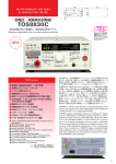
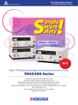
1
PART NO. IB027963 Mar. 2015 Search by Topic 8 Component Names 10 1 General Description 13 Product Overview 14 Options 16 2 Installation and Preparation 19 User’s Manual Connecting the Power Cord 20 Using the Protection Cover 21 Turning the Power On 22 Connecting to the Device under Test (DUT) 24 3 Safety Precautions for Testing 27 Pre-Test Inspection 28 Testing Precautions 28 Remote Control Precautions 29 Interrupting Testing or Operations 29 Emergency Measures 29 Forbidden Actions 30 About Malfunctions 30 To Use the Product for a Long Time Free of Malfunctions 30 4 Withstanding Voltage Tester TOS5200 5 6 Panel Operation Basics 31 Parts of the Screen 32 Panel Operations 34 Panel Memory 37 7 Withstanding Voltage Test 39 About Judgment 40 Invalid Settings 40 Setting Test Conditions 41 CONFIG Settings 44 Starting a Test 48 Finishing a Test 51 8 App External Control 53 SIGNAL I/O Connector 54 Starting a Test 57 Recalling Panel Memory and Test Modes 57 Interlock Feature 58 STATUS OUT connector 59 Maintenance 61 Pre-Test Inspection 62 Specifications 63 Appendix 71 DANGER This product generates high voltage! ż Improper operation can lead to serious accidents. ż To prevent accidents, be sure to read the section “Safety Precautions during Testing” in this manual. ż Keep this manual close to the product so that the operators can read the manual at any time. List of Default Settings 72 Protection Functions 74 Test Start Operation and Display 75 Troubleshooting 76 Trademarks About the Manuals These manuals are intended for users of the Withstanding Voltage Tester and their instructors. Explanations are given under the presumption that the reader has knowledge related to electricity. Microsoft, Windows, and Visual Basic are registered trademarks of Microsoft Corporation in the United States and/or other countries. All company names and product names used in this manual are trademarks or registered trademarks of their respective companies. Manual construction Copyrights ■ Setup Guide The contents of this manual may not be reproduced, in whole or in part, without the prior consent of the copyright holder. This manual is intended for first-time users of the product. It gives an overview of the product, connecting procedures, safety precautions, etc. Please read this manual before you operate the product. The specifications of this product and the contents of this manual are subject to change without prior notice. © 2014 Kikusui Electronics Corporation ■ Quick Reference The quick reference briefly explains the control panel and the basic operation of it. Checking the Package Contents ■ Safety Information This document contains general safety precautions for this product. Keep them in mind and make sure to observe them. ■ User’s Manual (this manual, PDF) This manual is intended for first-time users of this product. It provides an overview of the product, notes on usage, and specifications. It also explains how to connect the product, configure the product, operate the product, perform maintenance on the product, and so on. When you receive the product, check that all accessories are included and that the accessories have not been damaged during transportation. If any of the accessories are damaged or missing, contact your Kikusui agent or distributor. We recommend that you save all packing materials, in case the product needs to be transported at a later date. or ■ Communication Interface Manual (PDF) This manual explains how to control the product remotely using commands. It is included on the CD-ROM. The interface manual is written for readers with sufficient basic knowledge of how to control measuring instruments using a PC. Rating: 125 Vac, 10 A Plug: NEMA5-15 [85-AA-0003] Power cord (1 pc.) or Rating: 250 Vac, 10 A Plug: CEE7/7 [85-AA-0005] Rating: 250 Vac, 10 A Plug: GB1002 [85-10-0790] The power cord that is provided varies depending on the destination for the product at the factory-shipment. PDF files are included in the accompanying CD-ROM. You can view the PDF files using Adobe Reader 9.2 or later. Every effort has been made to ensure the accuracy of this manual. However, if you have any questions or find any errors or omissions, please contact your Kikusui agent or distributor. If you find any misplaced or missing pages in the manuals, they will be replaced. If the manual gets lost or soiled, a new copy can be provided for a fee. In either case, please contact your Kikusui agent or distributor. At that time, inform your agent or distributor of the “Part No.” written on the front cover of this manual. High-voltage test lead (1 set) [TL31-TOS] High-voltage warning sticker (1 pc.) [A8-210-203] SIGNAL I/O plug (1 set) Assembly type (D-sub plug unit) Japanese (1 sheet): [Z1-006-150] English (1 sheet): [Z1-006-152] CD-ROM (1 pc.) Quick Reference Setup Guide (1 pc.) [Z1-006-140] Safety Information (1 pc.) [Z1-005-040] After you have finished reading this manual, store it so that you can use it for reference at any time. Firmware versions that this manual covers This manual covers firmware versions 1.0X.When contacting us about the product, please provide us with: Model (marked in the top section of the front panel) The firmware version (see page 23) The serial number (marked in the bottom section of the rear panel) 2 TOS5200 Notes to the supervisor • If the operators cannot understand the language used in this manual, translate the manuals into the appropriate language. • Make sure that the operators understand the information in this manual before they operate this product. • Keep this manual close to the product so that the operators can read the manual at any time. • If the tester will be used to repeatedly perform tests with fixed conditions, such as when being used as part of a manufacturing line, attach the protection cover to ensure safe operation of the tester. This is useful in preventing incorrect operation of the tester. Dangerous Operations You will receive a potentially fatal electric shock if: • You touch an output terminal while output is being generated. • You touch a test lead that is connected to an output terminal while output is being generated. • You touch the device under test (DUT) while output is being generated. • You touch a location that is electrically connected to an output terminal while output is being generated. You may receive a potentially fatal electric shock if: • You operate the tester without grounding it. • You operate the tester without using rubber gloves for electrical work. • You come close to a location that is electrically connected to an output terminal while output is being generated. TOS5200 3 Notations Used in This Manual Safety Precautions When using this product, be sure to observe the “Safety Precautions” in the Safety information manual. • The TOS5200 Withstanding Voltage Tester is also referred to as the TOS5200. • Device under test is also referred to as DUT. Precautions Concerning Installation Location When installing this product, be sure to observe the “Precautions Concerning Installation Location” in the Safety information manual. The following precautions pertain only to this product. • When installing this product, be sure to observe the temperature and humidity ranges indicated below. Operating temperature range: 0 °C to +40 °C (32 °F to 104 °F) Operating humidity range: 20 %rh to 80 %rh (no condensation) • When storing this product, be sure to observe the temperature and humidity ranges indicated below. Storage temperature range: -20 °C to +70 °C (-4 °F to 158 °F) Storage humidity range: 90 %rh or less (no condensation) • Do not use the product in a poorly ventilated location. The product uses forced air cooling. It sucks air through the inlet holes on its right, and left panels, and then expels air through its rear panel. Secure adequate space around the product’s inlet and outlet holes to prevent the possibility of fire caused by accumulation of heat. Allow at least 20 cm of space between the inlet and outlet holes on the side and rear panels and the walls (or obstacles). Hot air (approximately 20°C, 68 °F, hotter than the ambient temperature) is expelled from the outlet holes. Do not place objects that are affected by heat near the air outlet. • The term “PC” is used to refer generally to both personal computers and workstations. • The following markings are used in the explanations in this manual. WARNING Indicates a potentially hazardous situation which, if ignored, could result in death or serious injury. CAUTION Indicates a potentially hazardous situation which, if ignored, may result in damage to the product or other property. Indicates information that you should know. DESCRIPTION Explanation of terminology or operation principle. See Indicates a reference to detailed information. SHIFT+key name (blue letters) Indicates an operation that requires you to press a key indicated in blue letters while holding down SHIFT. Memo Indicates useful information. Left panel inlet holes Right panel inlet holes • Do not use this product near highly sensitive measuring instruments or receivers. Noise generated by this product may affect other devices. At a test voltage of 3 kV or greater, the product may produce corona discharge between its test lead clips. This will generate a significant amount of broadband RF emission. To minimize this effect, keep the alligator clips away from each other. Also, keep the alligator clips and test leads away from conducting surfaces, especially sharp metal edges. 4 TOS5200 Contents About the Manuals .................................................................................................. 2 Checking the Package Contents ............................................................................. 2 Notes to the supervisor ........................................................................................... 3 Dangerous Operations ............................................................................................ 3 Safety Precautions .................................................................................................. 4 Precautions Concerning Installation Location ......................................................... 4 Notations Used in This Manual ............................................................................... 4 Search by Topic ....................................................................................................... 8 Component Names ................................................................................................ 10 1 General Description 2 Installation and Preparation 3 Safety Precautions for Testing 4 TOS5200 Product Overview......................................................................................................................................................... 14 Features .............................................................................................................. 14 Options .............................................................................................................................................................................. 16 Connecting the Power Cord.................................................................................................................................... 20 Using the Protection Cover ..................................................................................................................................... 21 Turning the Power On................................................................................................................................................ 22 Checking indicators and the status of the interlock feature................................. 22 Turning the POWER switch on....................................................................................................... 23 Turning the POWER switch off............................................................................ 23 Connecting to the Device under Test (DUT) .................................................................................................. 24 Using test leads................................................................................................... 24 Using the optional high voltage test probe (model HP01A-TOS/HP02A-TOS) ...................................................................... 26 Disconnecting test leads from the DUT............................................................... 26 Pre-Test Inspection ..................................................................................................................................................... 28 Testing Precautions .................................................................................................................................................... 28 Remote Control Precautions .................................................................................................................................. 29 Interrupting Testing or Operations....................................................................................................................... 29 Emergency Measures ................................................................................................................................................ 29 Forbidden Actions ........................................................................................................................................................ 30 Turning the power on and off repeatedly............................................................. 30 About Malfunctions ...................................................................................................................................................... 30 To Use the Product for a Long Time Free of Malfunctions ..................................................................... 30 Panel Operation Basics Parts of the Screen...................................................................................................................................................... 32 Panel Operations.......................................................................................................................................................... 34 Switching screens ............................................................................................... 34 Selecting items ....................................................................................................................................... 35 Entering values.................................................................................................... 35 Locking panel operations (key lock) .................................................................... 36 Talk mode............................................................................................................ 36 Panel Memory................................................................................................................................................................ 37 5 Saving test conditions.......................................................................................................................... 37 Recalling test conditions..................................................................................................................... 38 5 Withstanding Voltage Test 6 External Control 7 Maintenance 8 Specifications About Judgment............................................................................................................................................................. 40 Effectiveness of the lower limit............................................................................ 40 Invalid Settings............................................................................................................................................................... 40 Setting Test Conditions.............................................................................................................................................. 41 Test conditions (basic items)............................................................................... 41 Test conditions (additional items)........................................................................ 42 CONFIG Settings .......................................................................................................................................................... 44 CONFIG 1 settings.............................................................................................. 44 CONFIG 2 settings.............................................................................................. 46 Starting a Test ................................................................................................................................................................ 48 To start a test ...................................................................................................... 48 When a test starts ............................................................................................... 48 To change the voltage setting during a test ........................................................ 49 If you cannot start testing .................................................................................... 49 Finishing a Test.............................................................................................................................................................. 51 To stop a test ...................................................................................................... 51 When a test finishes............................................................................................ 51 To clear judgment results................................................................................................................... 52 SIGNAL I/O Connector............................................................................................................................................... 54 SIGNAL I/O specifications .................................................................................. 54 Internal construction ............................................................................................................................. 56 Input signal usage example ................................................................................ 56 Output signal usage example ............................................................................. 56 Starting a Test ................................................................................................................................................................ 57 Recalling Panel Memory and Test Modes ....................................................................................................... 57 Interlock Feature ........................................................................................................................................................... 58 How to use the interlock feature ......................................................................... 59 STATUS OUT connector........................................................................................................................................... 59 Pre-Test Inspection...................................................................................................................................................... 62 Inspection of test leads and the judgment feature .............................................. 62 Calibration ........................................................................................................... 62 Withstanding voltage tester................................................................................. 64 Other features.......................................................................................................................................... 66 Interfaces.................................................................................................................................................... 67 General........................................................................................................................................................ 69 Outline drawing ................................................................................................... 70 Appendix A List of Default Settings ............................................................72 Initializing the TOS5200 ...................................................................................... 72 B 6 Protection Functions ...............................................................74 TOS5200 C Test Start Operation and Display............................................ 75 D Troubleshooting ....................................................................... 76 Index ........................................................... 79 TOS5200 7 Search by Topic Preparation Setup • What accessories are included in the package? ➔ “Checking the Package Contents” p.2 • Before I start testing, I want to check that the TOS5200 is operating safely. ➔ “Turning the Power On” p.22 p.24 • I want to check that measurements are being performed correctly before I start testing. ➔ “Pre-Test Inspection” 8 p.42 ➔ “CONFIG Settings” p.44 • How are measured values judged? p.40 • How does the TOS5200 display the judgment results? ➔ “When a test finishes” p.62 p.51 • How can I hold the PASS judgment result? ➔ “Judgment result hold time (Pass Hold)” • I want to know more about the interlock feature. ➔ “Interlock Feature” ➔ “Test conditions (additional items)” ➔ “About Judgment” • How do I use each of the two test leads? ➔ “Using test leads” • Other than the basic settings that are shown on the panel, what test conditions can be set? p.45 p.58 TOS5200 Operation Maintenance • How do I save the present test conditions and use them later? ➔ “Panel Memory” p.37 ➔ “Pre-Test Inspection” • How do I start tests with a greater level of safety? ➔ “Double action feature” • How do I check that the test leads are not damaged (for example, that they have no breaks)? p.45 • How do I prevent unintentional key operations from changing the test conditions? • What do I need to keep in mind to use the TOS5200 for a long time without malfunctions? ➔ “To Use the Product for a Long Time Free of Malfunctions” ➔ “Using the Protection Cover” p.21 ➔ “Locking panel operations (key lock)” p.36 p.62 p.30 • How do I control the TOS5200 using external signal input? ➔ “SIGNAL I/O Connector” p.54 • How do I release the interlock feature? ➔ “Turning the Power On” p.22 Troubleshooting See “Troubleshooting” on page 76. TOS5200 9 Component Names Front Panel 1 TOS5200 AC WITHSTANDING VOLTAGE TESTER 4 3 2 ACW MEMORY 1 READY READY TEST TEST PASS PASS FAIL PROTECTION LIMIT 50Hz 60Hz RMS AVE CONFIG MORE CAL RMT 1 UPPER LOWER W COMP A kV FAIL 5 6 START 2 2 MT RISE TEST Mȍ mA 3 3 RECALL s STOP OUTPUT DANGER HIGH VOLTAGE FUNCTION VOLTAGE CURRENT TIMER ACW SET UPR/LWR TEST/RISE MORE CONFIG LIMIT ON/OFF ON/OFF KEY LOCK LOW LOCAL RESET SHIFT REMOTE USB POWER 5kV MAX 7 8 Test conditions 9 10 11 12 13 14 15 16 17 18 19 operating unit The protection cover is attached to the TOS5200 when the product is shipped from the factory. 20 No. 1 2 3 10 Loosen the screw and pull this part towards you to remove the cover. Name Function DANGER LED Lights in red when a test is being performed. p.48 READY: Lights in white when the TOS5200 is ready to perform a test. p.48 TEST: Lights in red when a test is being performed. p.48 PASS: Lights in green when a test passes. p.51 FAIL: Lights in yellow when a test fails. p.51 Displays the settings, measured values, and other information. p.32 Status indicators Display See TOS5200 No. Name Function See Press these keys to display the settings that are saved to memory. When test conditions or configuration items are being set, these keys correspond to the menus displayed on the screen. 4 MEMORY keys MEMORY 1 key: Displays the settings saved to MEMORY 1. MEMORY 2 key: Displays the settings saved to MEMORY 2. MEMORY 3 key: Displays the settings saved to MEMORY 3. RECALL key: Recalls settings from panel memory. +SHIFT key:1 Saves the current settings to panel memory. 5 START switch Starts testing. 6 STOP switch Stops testing and clears the current status. 7 HIGH VOLTAGE terminal This terminal is for the high-voltage line of the tester output. p.24 8 LOW VOLTAGE terminal This terminal is for the low-voltage line of the tester output (with cable lock). p.24 p.37 , p.44 p.48 p.51 ,p.74 FUNCTION key (ACW key) Does not use. CONFIG key +SHIFT key:1 Displays the CONFIG setup screen. 10 Rotary knob Changes settings. 11 Screw hole Fasten a screw to this hole to fix the protection cover in place. SET key Press to select the voltage setting. LIMIT key +SHIFT key:1 Selects the voltage limit setting. UPR/ LWR key Press to alternately select the upper and lower current limits. ON/ OFF key +SHIFT key:1 Turns the lower limit judgment feature on and off. REMOTE connector Specialized connector for connecting the optional remote control box, RC01TOS/RC02-TOS, or the high voltage test probe, HP01A-TOS/HP02A-TOS. TEST/ RISE key Press to alternately select the test time and voltage rise time. ON/ OFF key +SHIFT key:1 Turns the test time (Test Time) on and off. USB port USB interface connector. LOCAL key Switches between local mode and remote mode. — SHIFT key Press to access the features that are written in blue. — MORE key Press to select additional test condition settings. Frequency, start voltage, voltage fall time, and measurement mode KEY LOCK key +SHIFT key:1 Locks panel key operations (settings and changes). p.36 19 POWER switch Turns the power on [ ] and off [ p.22 20 Protection cover Cover designed to prevent incorrect operation of the TOS5200. 9 12 13 14 15 16 17 18 1 — p.44 p.35 ,p.41 ,p.44 — p.35 ,p.41 p.35 ,p.41 p.16 , p.26 p.35 ,p.41 Communication interface manual ]. p.41 ,p.42 p.21 This indicates an operation that requires you to press a key while holding down SHIFT. TOS5200 11 Rear Panel 1 3 2 WARNING DO NOT REMOVE COVERS. NO OPERATOR SERVICEABLE PARTS INSIDE. REFER SERVICING TO QUALIFIED SERVICE PERSONNEL. UNPLUG THE MAINS SUPPLY CORD BEFORE HANDLING THE CORD OR LOAD WIRES. AC INPUT 100 - 240V 50- 60Hz 800VA MAX 10 STATUS OUT COM + RS232C SIGNAL I / O STRIP-GAUGE AWG 10 mm 24-16 KIKUSUI ELECTRONICS CORP. 4 No. 1 12 xxxxxxx-x 5 6 7 Name Function 1 Chassis terminal Functional ground terminal1 2 AC LINE connector AC inlet 3 Air outlet Air outlet for cooling 4 STATUS OUT connector Connector for connecting the optional warning light unit, PL02-TOS 5 Serial number The product’s serial number — 6 RS232C port RS232C interface connector Communication interface manual 7 SIGNAL I/O connector External control signal connector See — p.20 — p.17 , p.59 p.54 A multipurpose ground terminal provided for the stable operation of the TOS5200. Use it if necessary. TOS5200 General Description This chapter gives an overview of the TOS5200 and explains the options that are available for it. Product Overview The TOS5200 Withstanding Voltage Tester performs withstanding voltage tests, which is one of the four types of tests1 that are required for ensuring the safety of electrical products. This product can perform AC withstanding voltage tests on electrical products and electrical components in accordance with the requirements of safety and electrical standards and ordinances such as IEC, EN, UL, VDE, and JIS. It is suited to (1) research and development installations, (2) test facilities for quality assurance testing and standard certification, and (3) manufacturing lines. The withstanding voltage tester is easy to use, safe, and reliable. Features ● Newly developed constant-voltage output for stable testing The TOS5200 is not affected by AC line interference. Because the output voltage is maintained at a fixed value even if the AC line voltage or frequency changes, stable tests can be performed even in locations where the power supply is unstable. The AC inlet is designed for worldwide use. The TOS5200 can be used without modification provided the nominal power supply voltage is within the range of 100 Vac to 240 Vac (90 Vac to 250 Vac) and the frequency is within the range of 47 Hz to 63 Hz. ● Rise time control feature that gradually increases the test voltage Instead of immediately applying the specified test voltage to the DUT after the test begins, this makes it possible to perform tests in which the voltage is raised gradually to the test voltage. As required by withstanding voltage tests defined by standards such as IEC and UL, this makes it possible to perform tests in which no more than half of the test voltage is applied at the start of the test, and the test voltage is gradually reached over the specified time. ● Fall time control feature that gradually decreases the test voltage The test voltage can be gradually decreased after a PASS judgment occurs during an AC withstanding voltage test. ● Window comparator feature for setting upper and lower judgment limits You can set not only the upper limit, but the lower limit as well. This is useful in determining whether there are breaks in test leads or whether there was a mistake during operations. This leads to highly reliable tests. ● Ability to save three sets of test conditions You can save three sets of test conditions. ● Improved safety In addition to having features that enable you to view the output voltage, the TOS5200 also enables you to set the voltage limits, so you can prevent a voltage greater than what is necessary from being generated unintentionally. This provides protection for the DUT. ● Standard-equipped USB port The TOS5200 is standard-equipped with a USB interface. You can use a PC or sequencer to control test conditions and read measured values and test results. 1 14 The four tests are the withstanding-voltage, insulation-resistance, earth-continuity, and leakagecurrent tests. TOS5200 Product Overview ● Light-weight and easy to move ● Protection against incorrect operations In addition to the key lock feature, the TOS5200 has a protection cover for the part of its panel that is used to change test conditions. This cover is useful in preventing incorrect operations when you want to perform tests with fixed conditions. TOS5200 1 General Description Even though the TOS5200 can generate 500 VA, which is sufficient for performing withstanding voltage tests, it only weighs 15 kg or less, so it can be moved by even a single person. 15 Options The following options are available for the TOS5200. For information about options, contact your Kikusui agent or distributor. Rack mount option Name Rack mount adapter Model Note KRA4-TOS For EIA inch racks KRA200-TOS For JIS millimeter racks KRA4-TOS Model RC01-TOS/RC02-TOS remote control box The remote control box can be used to start and stop withstanding voltage test. One model is for use with one hand, and the other model is for use with two hands. RC02-TOS (two hands) RC01-TOS (one hand) Model DD-5P/9P remote control adapter cable This is an adapter cable for connecting the product to a remote control box. 16 TOS5200 Options See p. 26 This is a probe for generating the test voltage. To prevent the test voltage from being generated unintentionally, this probe has been designed so that the test voltage is only generated when the user operates the probe with both hands. When using the test probe, make sure that the rated voltage is not exceeded. Rated voltage AC 4 kV DC 5 kV 1 General Description Model HP01A-TOS/HP02A-TOS high voltage test probe Model PL02-TOS warning light unit The warning light unit indicates that the TOS5200 is performing a test. This enables you to see that a test is in progress from a distance. TOS5200 17 This page is intentionally blank. 18 TOS5200 Installation and Preparation This chapter describes how to prepare this product for use. Connecting the Power Cord WARNING • This product conforms to IEC Safety Class I (equipment that has a protective conductor terminal). Be sure to earth ground the product to prevent electric shock. • The product is grounded through the power cord ground wire. Connect the protective conductor terminal to earth ground. • Use the supplied power cord to connect to the AC line. If the supplied power cord cannot be used because the rated voltage or the plug shape is incompatible, have a qualified engineer replace it with an appropriate power cord that is 3 m or less in length. If obtaining a power cord is difficult, contact your Kikusui agent or distributor. • The power cord with a plug can be used to disconnect the product from the AC power line in an emergency. Connect the plug to an easily accessible power outlet so that the plug can be removed from the outlet at any time. Be sure to provide adequate clearance around the power outlet. • Do not use the supplied power cord with other instruments. This product conforms to IEC Overvoltage Category II (energy-consuming equipment that is supplied from a fixed installation). In addition to the supplied power cord, Kikusui also provides other 200 V power cords with plugs (sold separately). 1 2 Check that the POWER switch is turned off. Check that the AC power line meets the nominal input rating of the product. The product can receive a nominal power supply voltage in the range of 100 Vac to 240 Vac (90 Vac to 250 Vac) that has a frequency in the range of 47 Hz to 63 Hz. 3 20 Connect the power cord to the rear-panel AC inlet, and then connect the power plug to an outlet that has a ground terminal. TOS5200 Using the Protection Cover Even when the cover is attached, you can still recall settings from memory, start and stop tests, perform remote operations, and control the TOS5200 through its USB port. If the tester will be used to repeatedly perform tests with fixed conditions, such as when being used as part of a manufacturing line, attach the protection cover to ensure safe operation of the tester. This is useful in preventing incorrect operation of the tester. If the cover is damaged or lost, contact your Kikusui agent or distributor. ■ Removing the protection cover OUTPUT CONFIG VOLTAGE CURRENT SET UPR/LWR R/ T/F LOCAL LIMIT ON/OFF ON/OFF TIMER KEY LOCK Loosen the screw, and then pull the hook centered at the bottom of the cover towards you to remove the protection cover from the panel. 2 Installation and Preparation When the product is shipped from the factory, a protection cover is attached to the front panel. This cover prevents unintentional changes to the test conditions. Remove this cover when you want to set the test conditions. SHIFT Pull the tab toward you. Loosen the screw. ■ Attaching the protection cover Insert the tabs at the top of the cover into the slots in the panel, push the bottom part of the cover until it is attached to the panel, and then use the screw to fix the cover in place. ■ Storing the protection cover TOS5200 bottom panel Use the screw to fasten the cover in place. When you want to use the TOS5200 without the protection cover attached, such as when you will repeatedly perform tests with frequently changed test conditions, you can store the protection cover on the product’s bottom panel. This is useful in preventing the cover from being lost. Use the screw to fix the cover to the product’s bottom panel. TOS5200 21 Turning the Power On Checking indicators and the status of the interlock feature See p. 58 See p. 58 The first time that you turn the POWER switch on after you purchase the TOS5200, the tester will be in PROTECTION mode through the interlock feature. Connect the included SIGNAL I/ O plug to the SIGNAL I/O connector to release the interlock feature. Only use the included SIGNAL I/O plug to easily release the PROTECTION mode. When you are actually performing tests, use the interlock feature to ensure safety. During withstanding voltage test in which you are using tools, (1) placing a cover over the DUT so that output is turned off whenever the cover is removed to prevent electric shock and (2) placing a safety fence around the work area where withstanding voltage test is being performed so that output is turned off whenever the fence is opened are both examples of effective safety measures. When the TOS5200 is turned on, a self-test is run, and all the indicators on the front panel light. To ensure safety, check that all the indicators light before you use the TOS5200. It is especially dangerous to use the tester if its DANGER LED is broken. When the power is turned on, the DANGER LED lights, but no voltage is generated. See p. 20 1 2 3 Check that the power cord and all cables are correctly connected. Check that nothing is connected to the SIGNAL I/O connector. Press the ( ) side of the front-panel POWER switch to turn the TOS5200 on. Check that all the front-panel indicators light. The firmware version screen will be displayed for a few seconds, and then a message indicating that the TOS5200 is in PROTECTION mode will be displayed. Check that the tester is in PROTECTION mode through the interlock feature. READY TEST PASS PROTECTION LIMIT 50Hz 60Hz TEST PASS FAIL 4 22 UPPER LOWER W COMP A kV FAIL READY RMS AVE CONFIG MORE CAL RMT 1 PROTECTION LIMIT 50Hz 60Hz RISE TEST Mȍ mA 3 s Firmware version screen RMS AVE CONFIG MORE CAL RMT 1 UPPER LOWER W COMP A kV 2 MT 2 MT RISE TEST Mȍ mA 3 Interlock protection mode s Press the ( ) side of the front-panel POWER switch to turn the TOS5200 off. TOS5200 Turning the Power On Turning the POWER switch on Connect the included SIGNAL I/O plug to the SIGNAL I/O connector. 2 3 Press the ( ) side of the POWER switch to turn the TOS5200 on. Connecting the SIGNAL I/O plug will release the interlock feature. Check the firmware version (Ver x.xx) that is displayed on the screen. Check that the firmware version screen is displayed for a few seconds, that the setup screen for setting the withstanding voltage test conditions is displayed thereafter, and that the tester is then in READY mode (that the READY LED lights). READY TEST PASS PROTECTION LIMIT 50Hz 60Hz TEST PASS PROTECTION LIMIT 50Hz 60Hz FAIL See p. 72 UPPER LOWER W COMP A kV FAIL READY RMS AVE CONFIG MORE CAL RMT 1 2 MT RISE TEST Mȍ mA 3 Firmware version 1.00 display example s 2 Installation and Preparation 1 RMS AVE CONFIG MORE CAL RMT 1 UPPER LOWER W COMP A kV 2 MT RISE TEST Mȍ mA 3 s The first time that the POWER switch is turned on, the firmware version is displayed, and then the setup screen for setting the withstanding voltage test conditions is displayed (with the factory default settings). The product stores the settings that are in use before it is turned off, so the next time that the POWER switch is turned on, the TOS5200 starts with these settings. Turning the POWER switch off Press the ( ) side of the POWER switch to turn the TOS5200 off. The panel settings that were in use immediately before the POWER switch was turned off are saved. If the POWER switch is turned off immediately after the settings have been changed, the last settings may not be stored. WARNING Risk of electric shock. • After you turn the POWER switch off, wait at least 10 seconds before you turn the POWER switch back on. It is dangerous to do otherwise, because the protective features of the product may not work effectively. This may cause the product to malfunction, and it may reduce the life of the POWER switch and internal parts such as the fuses. • Except in an emergency, do not turn the POWER switch off while output is being generated. TOS5200 23 Connecting to the Device under Test (DUT) WARNING Risk of electric shock. During testing (while the TEST LED or DANGER LED is lit), never touch the HIGH VOLTAGE terminal, test leads, and DUT. Using test leads WARNING Risk of electric shock. Never come close to this area during testing. • Parts of the included test leads near the alligator clips protrude from the vinyl insulation when the wires are connected. These parts are dangerous. Never come close to these parts during testing. • If connections are incomplete, the entire DUT may be charged to a high voltage. This is dangerous, so be sure to connect the DUT correctly. • Be sure to connect the low-voltage test lead (black) first. 1 Check that the POWER switch is off and that the DANGER LED is off. TOS5200 POWER OUTPUT DANGER See p. 62 2 3 HIGH VOLTAGE Off Off Check that there are no tears or breaks in the test lead insulation. Raise the front-panel LOW VOLTAGE terminal’s cable lock, and then connect the low-voltage test lead (black). Raise the cable lock. Low-voltage test lead (black) 4 Lower the cable lock to secure the lead in place. Lower the cable lock. Low-voltage test lead (black) 24 TOS5200 Connecting to the Device under Test (DUT) Connect the low-voltage test lead (black) to the DUT. Connect the high-voltage test lead (red) to the DUT. Connect the high-voltage test lead (red) to the front-panel HIGH VOLTAGE terminal. Low-voltage test lead (black) High-voltage test lead (red) 8 Check that the DANGER LED is turned off. TOS5200 OUTPUT DANGER 2 Installation and Preparation 5 6 7 Off Reducing the effect of noise Noise may be generated if the outputs are shorted or if the DUT insulation is damaged. Electronic devices in the surrounding area may malfunction due to the effect of this noise. To reduce the effect of noise, connect a toroidal core or a resistor of approximately 470 Ω between the tips of the high- and low-voltage test leads and the DUT. Connect the toroidal core or resistor as close to the DUT as possible. If you are connecting a toroidal core, it is effective to wrap the test leads two to three times around a type of core that can be snapped on and that is often used with power cables. This type of core is usually approximately 20 mm in diameter. If you are connecting a resistor, pay close attention to the power rating of the resistor. When the upper limit is 10 mA or less, connect a resistor of approximately 470 Ω (3 W, 30 kV impulse withstanding voltage). Because this resistor causes the voltage to fall, the voltage that is actually applied to the DUT is slightly lower than the voltage that is generated from the product’s output terminals (when a 10 mA current flows, the voltage falls approximately 10 V). These methods are extremely useful in reducing the effect of noise. Connect the toroidal core or resistor as close to the DUT as possible. Toroidal core HIGH VOLTAGE terminal HIGH VOLTAGE terminal DUT DUT LOW terminal LOW terminal 470 Ω, 3 W Toroidal core TOS5200 TOS5200 470 Ω, 3 W TOS5200 25 Connecting to the Device under Test (DUT) Using the optional high voltage test probe (model HP01A-TOS/HP02A-TOS) See p. 17 If you use the optional test probe instead of the test leads, you can use hands-on control to start tests. For details, see the “OPERATION MANUAL HIGH VOLTAGE TEST PROBE HP01A-TOS/HP02A-TOS.” Disconnecting test leads from the DUT 26 1 2 Check that the POWER switch is off and that the DANGER LED is off. 3 4 Disconnect the high-voltage test lead (red) from the DUT. Disconnect the high-voltage test lead (red) from the front-panel HIGH VOLTAGE terminal. Disconnect the low-voltage test lead (black). You can disconnect the low-voltage test lead (black) first from either the DUT or the TOS5200. TOS5200 Safety Precautions for Testing This chapter describes the precautions that must be followed to perform tests safely. Pre-Test Inspection WARNING Risk of electric shock. • During testing, this product supplies a voltage of at least 5 kVac to an external device. Handling this tester improperly may lead to a fatal accident. To prevent accidents, strictly follow the precautions and always pay the utmost attention to safety concerns when you operate the TOS5200. • This product conforms to IEC Safety Class I (equipment that has a protective conductor terminal). Be sure to earth ground the product to prevent electric shock. • The product is grounded through the power cord ground wire. Connect the protective conductor terminal to earth ground. • During testing, be sure to wear rubber gloves for electrical work. Check the following items before you start testing, and always follow the precautions. ● The power cord is connected to a properly grounded outlet. ● There is no damage such as tears or breaks in the test lead insulation. ● When the POWER switch is turned on, the DANGER LED and the status indicators light. ● During testing, do not touch the items that are charged to a high voltage: the DUT, the test leads, and the areas near the output terminals. ● During testing, do not turn the POWER switch off except in an emergency. Testing Precautions During testing, the TEST and DANGER LEDs light. When these LEDs are lit, the TOS5200 is generating a high voltage. During testing, be sure to wear rubber gloves for electrical work. If obtaining these gloves is difficult, contact your Kikusui agent or distributor. Lit TEST OUTPUT DANGER 28 Lit The TEST and DANGER LEDs light. The TEST LED lights in red. TOS5200 Remote Control Precautions When you are controlling the TOS5200 remotely, external signals are used to turn the high voltage on and off. To prevent accidents, follow the safety measures given below. ● Make sure that high voltages are not generated unintentionally. Interrupting Testing or Operations START Before you change test conditions or other settings, press the STOP switch, and then be sure to check the following items to ensure safety. If you will not use the product for some time or if the operator will be away from the product, be sure to turn the POWER switch off. 3 Safety Precautions for ● Make it impossible to touch the DUT, test leads, test probes, and the areas near the output terminals when high voltages are being generated. STOP ● The TEST and DANGER LEDs are both off. Emergency Measures There are two actions that you must carry out if, due to a malfunction in the product or the DUT, there is a possibility of an emergency occurring such as electric shock or damage to the DUT. ● Turn the POWER switch off. ● Remove the power cord plug from the outlet. Turn the POWER switch off. Remove the power plug from the outlet. POWER Off TOS5200 29 Forbidden Actions Turning the power on and off repeatedly After you turn the POWER switch off, wait for at least 10 seconds before you turn it back on. It is dangerous to do otherwise, because the protective features of the product may not work effectively. This may cause the product to malfunction, and it may reduce the life of the POWER switch and internal parts such as the fuses. About Malfunctions WARNING Risk of electric shock. • Until you get the product fixed, make sure that nobody can use it. • For repairs, contact your Kikusui agent or distributor. If the TOS5200 is in one of the states explained below, it may be malfunctioning in a very dangerous manner—it may not be possible to turn off the high voltage that is being generated. If the tester is not operating properly, it may be generating a high voltage irrespective of the settings made by the operator. Immediately turn the POWER switch off, and disconnect the power cord from the outlet. Stop using the product immediately, and contact your Kikusui agent or distributor. ● Even when you press the STOP switch, the DANGER LED remains lit. ● During tests, the DANGER LED does not light. To Use the Product for a Long Time Free of Malfunctions Taking size, weight, and cost into consideration, the heat dissipation capability of the voltage generator that is used for withstanding voltage tests has been designed to be one half that of the rated output. Use the TOS5200 within the following limits. If you use the product in a manner that exceeds these limits, the output section may overheat, and the internal protection circuits may be activated. If this happens, stop testing, and wait until the TOS5200 returns to its normal temperature. ■ Output limits during withstanding voltage testing Ambient temperature Upper limit Pause time Output time t ≤ 40 °C 50 mA < i ≤ 110 mA Greater than or equal to the output time 30 min. max. i ≤ 50 mA Not necessary Continuous output possible (Output time = voltage rise time + test time + voltage fall time) 30 TOS5200 Panel Operation Basics This chapter describes how to select items on the screen and how to enter values. Parts of the Screen The screen that is used to set the basic test conditions is made up of the four parts shown below. Status indicators TEST LIMIT 50Hz 60Hz FAIL See p. 72 Icon area RMS AVE CONFIG MORE CAL RMT 1 PROTECTION READY PASS Test condition display UPPER LOWER W COMP A kV 2 MT RISE TEST Mȍ mA 3 Data input s area To reset the TOS5200 to the factory default settings, hold down SHIFT, and turn the POWER switch on. Status indicators These display the status. Display Description READY Lights when the TOS5200 is ready to perform a test TEST Lights when a test is being performed PASS Lights when a test result is success FAIL Lights when a test result is fail PROTECTION Lights when a protection function is activated Test condition display This displays test conditions. 32 Display Description RMS Lights when the measurement mode is true rms response AVE Lights when the measurement mode is mean-value response CONFIG Lights when CONFIG items are displayed MORE Lights when items other than CONFIG items are displayed CAL Lights during calibration RMT Lights when the TOS5200 is being remotely controlled LIMIT Lights when a limit voltage is set 50 Hz Lights when the frequency is 50 Hz 60 Hz Lights when the frequency is 60 Hz UPPER Lights when the ammeter is displaying the upper limit. LOWER Lights when the ammeter is displaying the lower limit. W COMP Lights during lower limit judgment RISE Lights when the voltage rise time is displayed TEST Lights when the test time is displayed TOS5200 Parts of the Screen Icon area The TOS5200 status is displayed using icons or characters. Display/icon - 1 2 3 Status See Model RC01-TOS/RC02-TOS remote control box connected p. 16 Keys locked p. 36 Recalled memory number or CONFIG setup screen number p. 37 Data input area The selected item blinks. READY TEST PASS FAIL PROTECTION LIMIT 50Hz 60Hz RMS AVE CONFIG MORE CAL RMT 1 UPPER LOWER W COMP A kV 2 MT RISE TEST Mȍ mA The selected item (blinking) TOS5200 3 s 4 Panel Operation Basics This area is used to enter the test voltage, limit voltage, upper and lower current limits, test time, CONFIG values, and additional test items. 33 Panel Operations Switching screens Memo The screen that first appears when the POWER switch is turned on is referred to as the basic setup screen. See p. 42 See p. 44 , p. 46 On the TOS5200, you need to change the setup screen depending on the item you want to set. From the basic setup screen, you can switch to the additional test conditions setup screen or CONFIG setup screen. To display the setup screen for additional test conditions, press MORE. To display the CONFIG setup screen, press CONFIG (SHIFT+FUNCTION). Press once to show the CONFIG 1 screen and twice to show the CONFIG 2 screen. To return to the basic setup screen, press STOP. Basic setup screen READY TEST PASS PROTECTION LIMIT 50Hz 60Hz RMS AVE CONFIG MORE CAL RMT 1 UPPER LOWER W COMP A kV FAIL 2 MT RISE TEST Mȍ mA [MORE key] Additional test conditions setup screen READY TEST 3 PASS PROTECTION LIMIT 50Hz 60Hz UPPER LOWER W COMP A kV FAIL s RMS AVE CONFIG MORE CAL RMT 1 2 MT RISE TEST Mȍ mA 3 s [CONFIG (SHIFT+FUNCTION) key] CONFIG setup screen READY TEST PASS PROTECTION LIMIT 50Hz 60Hz 1 RMS AVE CONFIG MORE CAL RMT 1 UPPER LOWER W COMP A kV FAIL 2 MT RISE TEST Mȍ mA 3 s [CONFIG (SHIFT+FUNCTION) key] CONFIG setup screen READY TEST PASS PROTECTION LIMIT 50Hz 60Hz 2 RMS AVE CONFIG MORE CAL RMT 1 UPPER LOWER W COMP A kV FAIL 2 MT RISE TEST Mȍ mA To return to the basic setup screen, press STOP. 3 s To recall a memory entry, press MEMORY 1, MEMORY 2, or MEMORY 3. To save, press Recall while holding down SHIFT. MEMORY READY TEST PASS PROTECTION LIMIT 50Hz 60Hz TEST PASS FAIL 34 UPPER LOWER W COMP A kV FAIL READY RMS AVE CONFIG MORE CAL RMT 1 PROTECTION LIMIT 50Hz 60Hz 2 RISE TEST 3 Mȍ mA s RMS AVE CONFIG MORE CAL RMT 1 UPPER LOWER W COMP A kV MT 2 3 RECALL LOCAL 2 MT RISE TEST Mȍ mA 1 3 s SHIFT To save, press Recall while holding down SHIFT. TOS5200 Panel Operations Selecting items See p. 41 To select an item, use the SET, UPR/ LWR, or TEST key. RMS AVE CONFIG MORE CAL RMT 1 PROTECTION READY TEST LIMIT 50Hz 60Hz PASS A kV FAIL SET UPR/LWR TEST LIMIT ON/OFF ON/OFF MORE 2 MT UPPER LOWER W COMP RISE TEST 3 KEY LOCK LOCAL Mȍ mA s SHIFT On the basic setup screen, press SET to select the voltage. Example: Selecting the voltage (blinking) On the basic setup screen, hold down SHIFT and press SET to select the limit voltage. Example: Selecting the limit voltage (blinking) READY TEST RMS AVE CONFIG MORE CAL RMT 1 PROTECTION LIMIT 50Hz 60Hz PASS SET UPR/LWR LIMIT ON/OFF TEST MORE 2 MT UPPER LOWER W COMP RISE TEST 3 ON/OFF KEY LOCK LOCAL A kV FAIL Mȍ mA s SHIFT When you enter the setup screen for additional test conditions (MORE) or a CONFIG setup screen, the MEMORY 2 and MEMORY 3 keys become left and right movement keys. MORE Example: Selecting the frequency (blinking) See p. 42 4 Panel Operation Basics If the item that you want to select is not displayed, press LIMIT (SHIFT+SET), ON/OFF (SHIFT+UPR/LWR), ON/OFF (SHIFT+TEST), or press MORE key. MEMORY 1 PROTECTION READY TEST PASS LIMIT 50Hz 60Hz RMS AVE CONFIG MORE CAL RMT 1 UPPER LOWER W COMP A kV FAIL 2 MT RISE TEST Mȍ mA 3 s 2 3 RECALL Entering values You can set the value of the blinking item by turning the rotary knob. Rotary knob Turn the rotary knob to set the value. READY TEST PASS PROTECTION LIMIT 50Hz 60Hz FAIL RMS AVE CONFIG MORE CAL RMT 1 A kV 2 MT UPPER LOWER W COMP RISE TEST Mȍ mA 3 FUNCTION ACW s If you hold down SHIFT and turn the rotary knob, you can change the setting resolution. While you hold down SHIFT, the values change quickly. Rotary knob FUNCTION ACW LOCAL SHIFT TOS5200 35 Panel Operations Locking panel operations (key lock) The key lock feature can be used to prevent changes to the test conditions due to incorrect operations. To lock the panel operations, press KEY LOCK (SHIFT+MORE). In this state, only the START and STOP switches are enabled. When keys are locked, the key lock icon appears on the screen. If you try to use a locked key, the key lock icon ( ) blinks for approximately 2 seconds. To release the key lock, hold down KEY LOCK (SHIFT+MORE) until the key lock icon appears. READY TEST PASS FAIL See p. 21 PROTECTION LIMIT 50Hz 60Hz RMS AVE CONFIG MORE CAL RMT 1 UPPER LOWER W COMP A kV 2 MT RISE TEST Mȍ mA dis- MORE KEY LOCK 3 LOCAL s SHIFT If you will run tests using conditions that you have recalled from memory, we recommend that you use the protection cover. Talk mode This feature enables you to control the product in the same manner as remote control without using commands from a PC. It can reduce processing on the PC. If you turn talk mode on, you cannot control the product from a PC. To control the product from a PC, turn talk mode off. For details on talk mode, see the communication interface manual. 36 TOS5200 Panel Memory You can save up to three sets of test conditions (the test conditions currently being used) to internal memory. Test conditions and values that can be saved LIMIT 50Hz 60Hz A kV FAIL 2 MT UPPER LOWER W COMP RISE TEST Mȍ mA 3 s Test voltage 0.00 kV to 5.50 kV Output frequency 50 Hz/ 60 Hz Upper limit 0.01 mA to 110 mA Lower limit OFF/ 0.01 mA to 110 mA Test time OFF/ 0.1 s to 999 s Voltage rise time 0.1 s to 10.0 s Voltage fall time OFF/ 0.1 s Start voltage OFF/ 50 % 4 Panel Operation Basics TEST PASS RMS AVE CONFIG MORE CAL RMT 1 PROTECTION READY Initial panel memory settings Initially, memory numbers 1 to 3 contain withstanding voltage test conditions. Feel free to use these test conditions if they match the tests that you want to perform. For details on the test conditions that are initially contained in memory, see “Default panel memory values”. See p. 73 Saving test conditions 1 2 MEMORY 2 1 2 Display the basic setup screen, and then set the test conditions. Press MEMORY 1, MEMORY 2, or MEMORY 3 to select the memory number (1 to 3) in which you want to save the current test conditions. 3 RECALL 3 The selected memory number blinks. LOCAL + SHIFT 3 Press SHIFT+RECALL to save the conditions in the selected memory number. READY TEST PASS FAIL PROTECTION LIMIT 50Hz 60Hz RMS AVE CONFIG MORE CAL RMT 1 UPPER LOWER W COMP A kV 2 MT RISE TEST Mȍ mA 3 s Example of saving to memory number 1 After the test conditions have been saved, the basic setup screen is displayed in READY mode (the READY LED lights). TOS5200 37 Panel Memory Recalling test conditions MEMORY 1 1 1 Press MEMORY 1, MEMORY 2, or MEMORY 3 to specify the memory number (1 to 3) from which you want to recall test conditions. The test conditions that are saved in the memory number (1 to 3) that you specified are displayed. 2 3 RECALL 2 2 Press RECALL to recall the test conditions that are saved in the specified memory number. The basic setup screen is displayed, and the icon corresponding to the memory number is displayed in the icon area. The TOS5200 is now set to the recalled test conditions. READY TEST PASS FAIL PROTECTION LIMIT 50Hz 60Hz RMS AVE CONFIG MORE CAL RMT 1 UPPER LOWER W COMP A kV 2 MT RISE TEST Mȍ mA 3 s Example: The test conditions that were saved in MEMORY 2 have been recalled. If you change the recalled test conditions, the memory number disappears. Even if you set the test conditions back to the values that are stored in memory, the memory number will not reappear. 38 TOS5200 Withstanding Voltage Test This chapter explains withstanding voltage test, from how to set the test conditions to how to save test results. About Judgment The TOS5200 judges whether a test results in PASS, L-FAIL, or U-FAIL on the basis of the limits that are set in advance. Judgment result Description Display PASS When the test time elapses (TIMER is 0 seconds), if the condition “lower limit < measured value < upper limit” is true, the judgment result is PASS, and the test ends. PASS LED lights in Sounds for green. 50 ms.1 Measured value remains displayed for the length of time specified by Pass Hold. L-FAIL If the condition “lower limit ≥ measured value” is true, the judgment result is LOWER, and the test is immediately stopped. FAIL LED (yellow) and “LOWER” lights. U-FAIL If the condition “upper limit ≤ measured value” is true, the judgment result is UPPER, and the test is immediately stopped. FAIL LED (yellow) and “UPPER” lights. 1 Buzzer Sounds until STOP is pressed. The length of time that the buzzer sounds when a PASS judgment occurs is fixed to 50 ms. The specified Pass Hold time has no effect. Effectiveness of the lower limit Normally, even a good DUT will have a certain degree of leakage current. Setting the upper limits just within the boundaries of the characteristic range of the DUT is useful in detecting breaks in the test leads and poor connections, enabling you to perform highly reliable testing. In withstanding voltage tests, you can perform tests effectively by enabling the lower limit with W COMP. Invalid Settings If you specify an invalid value for a setting, a message blinks on the screen. While a message is blinking, the READY LED turns off, and you cannot start a test. You also cannot select other items. Specify a valid value. READY LED turns off READY TEST PASS PROTECTION LIMIT 50Hz 60Hz FAIL 40 LIMIT blinks RMS AVE CONFIG MORE CAL RMT 1 UPPER LOWER W COMP A kV 2 MT RISE TEST Mȍ mA 3 s Example of LIMIT indicator blinking Message Description mA indicator blinking When the lower or upper limit is turned on, and the upper limit has been set lower than the lower limit. LIMIT indicator blinking When you try to set the test voltage higher than the set limit voltage. kV and mA indicators blinking simultaneously When the test voltage and the upper limit are set in the withstanding voltage test settings such that their product exceeds 550 VA. TOS5200 Setting Test Conditions Test condition Panel operation Basic item Test voltage (Voltage) SET key, rotary knob Limit voltage (LIMIT) LIMIT (SHIFT+SET) key, rotary knob Upper limit (UPPER) UPR/ LWR key, rotary knob Lower limit (LOWER) UPR/ LWR key, rotary knob on/ off ON/ OFF (SHIFT+UPR/ LWR) key Test time (TEST) TEST key, rotary knob on/ off ON/ OFF (SHIFT+ TEST) key Voltage rise time (RISE) TEST key, rotary knob Additional items See p. 24 See p. 40 MORE key, rotary knob Start voltage (Start Voltage) MORE key, rotary knob Voltage fall time (Fall Time) MORE key, rotary knob Voltage/current measurement mode (Measurement) MORE key, rotary knob 5 For details on how to select settings and enter values, see “Panel Operation Basics”. For details on how to connect the TOS5200 to the DUT, see “Connecting to the Device under Test (DUT)”. For details on the LOWER and UPPER settings, see also “About Judgment”. Withstanding Voltage Test See p. 31 Test voltage frequency (Frequency) Test conditions (basic items) READY TEST PASS PROTECTION LIMIT 50Hz 60Hz FAIL RMS AVE CONFIG MORE CAL RMT 1 UPPER LOWER W COMP 2 MT RISE TEST 3 SET UPR/LWR TEST LIMIT ON/OFF ON/OFF MORE KEY LOCK LOCAL A kV Mȍ mA s SHIFT Test voltage (Voltage) Sets the test voltage. You cannot specify a voltage that is greater than or equal to the limit voltage. Test voltage 0.00 kV to 5.50 kV Limit voltage (LIMIT) Sets the limit voltage. This prevents an unnecessarily high voltage from being applied to the DUT because of incorrect operations of the TOS5200. Limit voltage TOS5200 0.00 kV to 5.50 kV 41 Setting Test Conditions Upper limit (UPPER) Sets the upper current limit that is used in judgments. If a current that is greater than or equal to the upper limit is measured, a U-FAIL judgment occurs. Upper limit 0.01 mA to 110 mA Lower limit (LOWER) Sets the lower current limit that is used in judgments. While LOWER is on, if a current that is less than or equal to the lower limit is measured, an L-FAIL judgment occurs. You can turn on and off the lower limit function using the ON/OFF (SHIFT+UPR/LWR) key. Lower limit 0.01 mA to 110 mA Test time (TEST) Set the test time. The test time begins when the voltage rise time elapses and ends when the specified time elapses. You can turn on and off the test time using the ON/OFF (SHIFT+TEST) key. If the test time is set to off, PASS judgment is not performed. Press STOP to stop testing. Test time 0.1 s to 999 s Voltage rise time (RISE) Separate from the test time, you can set the time that the TOS5200 takes to raise the voltage to the test voltage. Voltage rise time 0.1 s to 10.0 s Test conditions (additional items) MORE Press MORE to display the items that are not displayed. Example: Selecting the frequency (blinking) MEMORY 1 READY TEST PASS FAIL PROTECTION LIMIT 50Hz 60Hz RMS AVE CONFIG MORE CAL RMT 1 UPPER LOWER W COMP A kV 2 MT RISE TEST Mȍ mA 3 s 2 3 RECALL Measurement mode setting [0: RMS, 1: AVE] Voltage fall time setting: [0: off, 1: on] Start voltage setting [0: off, 1: on] Frequency setting [0: 50 Hz, 1: 60 Hz] 42 TOS5200 Setting Test Conditions Memo On the More screen, use the MEMORY 2 and MEMORY 3 keys to move between settings. Each time you press one of these keys, the cursor moves to the next setting. After selecting a setting, use the rotary knob to set its value. 1 2 Press MORE to display the More Test Conditions setup (More) screen. Press MEMORY 2 or MEMORY 3 to move to the item that you want to set, and then use the rotary knob to set the value. Press STOP, or press a key other than MORE to exit the More Test Conditions setup screen and return to the basic setup screen. Frequency Sets the test voltage frequency. The test voltage frequency is set to 50 Hz (factory default setting). 60 Hz (1) The test voltage frequency is set to 60 Hz. Start voltage (Start Voltage) Separate from the test voltage, you can set the start voltage of withstanding voltage tests. You can set the start voltage to 50 % of the test voltage. The output voltage reaches this value approximately 0.1 seconds after the start of testing. off (0) The start voltage is not set (factory default setting). on (1) The start voltage is set to 50 % of the test voltage. READY LED lit Off TEST LED blinking TEST LED lit Output on Start voltage 5 Withstanding Voltage Test 50 Hz (0) 100 % Output Off 50 % 0.1 s Voltage rise time Voltage fall time (Fall Time) Separate from the test time, you can set the time that the TOS5200 takes to lower the voltage after a withstanding voltage test ends. This setting is used only when a PASS judgment occurs. off (0) The output voltage is shut off immediately after a test ends with a PASS judgment (factory default setting). on (1) The output voltage falls over approximately 0.1 seconds after a test ends with a PASS judgment. Measurement mode (Measurement) Selects the voltage/current measurement mode. RMS (0) Measurement is performed using true rms response (factory default setting). AVE (1) Measurement is performed using mean-value response. The measurement mode on Kikusui TOS9200 series, TOS8870A, TOS8850, TOS8850A, TOS5000 series, and TOS5000A series is mean-value response. TOS5200 43 CONFIG Settings CONFIG settings are provided on the CONFIG FUNCTION LOCAL ACW screen and CONFIG 2 screen. CONFIG 1 CONFIG 2 Double Action Double action feature H.V ON Output when there is residual voltage or during testing Momentary Momentary feature Test Output during testing when the test voltage is at the set value Fail Mode Fail mode feature Pass PASS judgment output Pass Hold PASS judgment result hold time Upper Fail Output when upper limit judgment is FAIL Pass Buzzer volume level for PASS judgment Lower Fail Output when lower limit judgment is FAIL Fail Buzzer volume level for FAIL judgment Ready Output when READY is displayed Baudrate RS232C baud rate Protection Output during PROTECTION mode Talk Mode Talk mode Power ON Output when the POWER switch is on 1 Press CONFIG (SHIFT+FUNCTION) to display the CONFIG setup screen. 2 Press MEMORY 2 or MEMORY 3 to move to the CONFIG item that you want to set, and then use the rotary knob to set the value. + SHIFT 1 Press once to show the CONFIG 1 screen and twice to show the CONFIG 2 screen. To exit from the CONFIG setup screen and return to the basic setup screen, press STOP. Memo The first screen that is displayed when you perform configuration settings is called CONFIG setup screen. If you enter CONFIG settings again without first turning the power off, the screen that you previously were viewing will be displayed. CONFIG 1 settings On the CONFIG 1 setup screen, you can set the test mode and buzzer volume level. Example: Selecting the double action feature (blinking) MEMORY 1 READY TEST PASS FAIL PROTECTION LIMIT 50Hz 60Hz RMS AVE CONFIG MORE CAL RMT 1 UPPER LOWER W COMP A kV 2 MT RISE TEST Mȍ mA 3 s 2 3 RECALL Talk mode setting [0: off, 1: on] RS232C baud rate setting [0: 9 600, 1: 19 200, 2: 38 400, 3: 57 600, 4: 115 200] FAIL judgment buzzer volume level setting [0 to 9: 10 setting levels] PASS judgment buzzer volume level setting [0 to 9: 10 setting levels] Judgment result hold time setting [0: 50 ms, 1: 100 ms, 2: 200 ms, 3: 1 s, 4: 2 s, 5: 5 s, 6: HOLD] Fail mode function setting [0: off, 1: on] Momentary function setting [0: off, 1: on] Double action feature setting [0: off, 1: on] 44 TOS5200 CONFIG Settings Double action feature This feature enables you to start a test by first pressing STOP and then pressing START within 0.5 seconds. If you do not press START within this time limit, the test does not start (the READY LED turns off). This feature ensures that tests are started safely because it requires you to use both the STOP and START switches. off (0) The double action feature is turned off (factory default setting). on (1) The double action feature is turned on. Momentary feature This feature enables you to perform tests only while you are pressing START. This ensures safe testing because it means that your hand must be fixed to the panel or to an optional RC01-TOS START switch. While this feature is on, testing stops as soon as you release START. The stop operation is the same as if you had pressed STOP. off (0) The momentary feature is turned off (factory default setting). on (1) The momentary feature is turned on. Fail mode feature This feature prevents FAIL judgments and protection modes from being cleared even when a stop signal is sent with a command. To clear the FAIL judgment when the fail mode feature is turned on, press STOP on the front panel. If you are using the optional high voltage test probe (HP01A-TOS/HP02A-TOS See p. 17 ), we recommend that you turn on the fail mode feature. When a test ends with a FAIL judgment or ends in protection mode, the FAIL judgment is not cleared even if you let go of the probe. Thus, you can definitely check the status. off (0) The fail mode feature is turned off (factory default setting). on (1) The fail mode feature is turned on. 5 Withstanding Voltage Test Using this feature with the optional RC02-TOS (two-hand-type remote control box See p. 16 ) provides an even higher level of safety. Judgment result hold time (Pass Hold) This feature enables you to set the length of time that the TOS5200 maintains a PASS judgment state. If you set Pass Hold to HOLD, the measured results remain displayed on the screen until you press STOP. When a FAIL judgment occurs, the FAIL judgment’s measured results remain displayed on the screen until you press STOP, regardless of the value of the Pass Hold setting. 50 ms (0) to 5.5 s (5) 0: 50 ms (factory default setting), 1: 100 ms, 2: 200 ms, 3: 1 s, 4: 2 s, 5: 5 s HOLD (6) The results are maintained until you press STOP. Buzzer volume level for PASS judgment (PASS) You can set the volume level of the buzzer that is sounded when a PASS judgment occurs. 0 to 9 TOS5200 0, 1, 2, 3 (factory default setting), 4, 5, 6, 7, 8, 9 45 CONFIG Settings Buzzer volume level for FAIL judgment (FAIL) You can set the volume level of the buzzer that is sounded when a FAIL judgment occurs. 0 to 9 0, 1, 2, 3, 4, 5 (factory default setting), 6, 7, 8, 9 RS232C baudrate You can set the baud rate for the RS232C interface. 9600 (0) to 115200 (4) 0: 9600 (factory default setting), 1: 19200 , 2: 38400, 3: 57600, 4: 115200 Talk mode See p. 68 This feature enables you to send test results and the like from the product through the RS232C interface without using commands from a PC. It can reduce processing on the PC. If you turn talk mode on, you cannot control the product from a PC. To control the product from a PC, turn talk mode off. off (0) Talk mode is not used (factory default setting). on (1) Talk mode is used. CONFIG 2 settings On the CONFIG 2 setup screen, you can set the output conditions when using the optional warning light unit, PL02-TOS. Example: Selecting H.V ON (blinking) READY TEST PASS FAIL PROTECTION LIMIT 50Hz 60Hz MEMORY RMS AVE CONFIG MORE CAL RMT 1 UPPER LOWER W COMP A kV 2 MT RISE TEST Mȍ mA 3 s 1 2 3 RECALL Power ON setting [0: off, 1: on] Protection setting [0: off, 1: on] Ready setting [0: off, 1: on] Lower Fail setting [0: off, 1: on] Upper Fail setting [0: off, 1: on] Pass setting [0: off, 1: on] Test setting [0: off, 1: on] H.V ON setting [0: off, 1: on] H.V ON Sets whether the 24 Vdc output is generated while there is a residual voltage and during testing. 46 off (0) The 24 Vdc output is turned off while there is a residual voltage and during testing (factory default setting). on (1) The 24 Vdc output is turned on while there is a residual voltage and during testing. TOS5200 CONFIG Settings Test Sets whether the 24 Vdc output is generated while tests are being performed with the test voltage at the specified voltage value. The 24 Vdc output is not generated during voltage rise time (Rise Time) and voltage fall time (Fall Time). off (0) The 24 Vdc output is turned off during testing (factory default setting). on (1) The 24 Vdc output is turned on during testing. Pass Sets whether the 24 Vdc output is generated after a PASS judgment has occurred. off (0) The 24 Vdc output is turned off during testing (factory default setting). on (1) The 24 Vdc output is turned on during testing. Sets whether the 24 Vdc output is generated after an upper limit FAIL judgment has occurred. off (0) The 24 Vdc output is turned off after an upper limit FAIL judgment occurs (factory default setting). on (1) The 24 Vdc output is turned on after an upper limit FAIL judgment occurs. Lower Fail Sets whether the 24 Vdc output is generated after a lower limit FAIL judgment has occurred. off (0) The 24 Vdc output is turned off after an lower limit FAIL judgment occurs (factory default setting). on (1) The 24 Vdc output is turned on after a lower limit FAIL judgment occurs. Withstanding Voltage Test 5 Upper Fail Ready Sets whether the 24 Vdc output is generated while the READY LED is lit. off (0) The 24 Vdc output is turned off while the READY LED is lit (factory default setting). on (1) The 24 Vdc output is turned on while the READY LED is lit. Protection Sets whether the 24 Vdc output is generated while the TOS5200 is in protection mode. off (0) The 24 Vdc output is turned off when the TOS5200 is in protection mode (factory default setting). on (1) The 24 Vdc output is turned on when the TOS5200 is in protection mode. Power ON Sets whether the 24 Vdc output is generated while the POWER switch is on. TOS5200 off (0) The 24 Vdc output is turned off when the POWER switch is turned on (factory default setting). on (1) The 24 Vdc output is turned on when the POWER switch is turned on. 47 Starting a Test WARNING Risk of electric shock. During testing, do not touch the test leads and the DUT. To start a test 1 2 Check that the TOS5200 is correctly connected to the DUT. When the READY LED lights in white, press START. TEST PASS LIMIT 50Hz 60Hz See p. 65 UPPER LOWER W COMP A kV FAIL See p. 49 RMS AVE CONFIG MORE CAL RMT 1 PROTECTION READY START 2 MT RISE TEST Mȍ mA 3 s If the test does not start, see “If you cannot start testing”. If you want to start another test after testing finishes, set a wait time between tests as necessary. When a test starts The TEST and DANGER LEDs light. The TEST LED lights in red. Lit TEST Lit OUTPUT DANGER The TEST and DANGER LEDs light. The TEST LED lights in red. If the start voltage and the voltage rise time have been set See p. 41 , p. 42 , p. 43 After the voltage rises to the start voltage or after the voltage rise time elapses, the TEST LED lights in red, and the test starts. While the voltage is rising, the TEST LED blinks in red, and the display counts up to the set rise time. Blinking READY TEST PASS FAIL 48 PROTECTION LIMIT 50Hz 60Hz RMS AVE CONFIG MORE CAL RMT 1 UPPER LOWER W COMP A kV 2 MT RISE TEST Mȍ mA 3 s Counts up the voltage rise time TOS5200 Starting a Test If the start voltage has been turned off and the voltage rise time has not been set After 0.1 seconds, the TEST LED lights in red, and the test starts. If the test time has been set or if the test time has been turned off The TEST LED lights in red during testing. If the test time has been turned on, the display counts down from the set test time. If it is set to OFF, the display counts up the test time. READY TEST PASS RMS AVE CONFIG MORE CAL RMT 1 PROTECTION LIMIT 50Hz 60Hz FAIL UPPER LOWER W COMP A kV 2 MT RISE TEST Mȍ mA 3 s The time display after you start testing differs depending on whether TIMER is set to ON or OFF. TIMER ON The timer’s remaining test time is counted down. TIMER OFF The elapsed test time is counted up. When the test time exceeds 999 seconds, “999” blinks. To change the voltage setting during a test While the TEST LED is lit in red, press SET to select the voltage setting value, and then use the rotary knob to change the value. The voltage is changed immediately. The changed voltage is immediately applied to the test, but the voltage value on the display shows the measured value. After the test finishes, when the TOS5200 returns to the READY state, the new voltage value is shown on the display. 5 Withstanding Voltage Test See p. 41 , p. 42 If you cannot start testing In the following conditions, you will not be able to start testing. The READY LED will not light. See p. 37 ● The memory number is not fixed while panel settings are being recalled from or saved to memory. See p. 51 , p. 54 ● STOP is being pressed (including when a STOP signal is being applied to the SIGNAL I/O connector). See p. 40 ● “mA” is blinking. The lower or upper limit is turned on, and the upper limit has been set lower than the lower limit. Specify a valid value. ● “kV” and “mA” are blinking simultaneously. When the test voltage and the upper limit are set in the withstanding voltage test settings such that their product exceeds 550 VA. Specify a valid value. TOS5200 49 Starting a Test ● “PASS” or “FAIL” is lit. You cannot start testing while a judgment result is displayed. Press STOP to switch the TOS5200 to the READY state. See p. 74 ● “PROTECTION” is lit. If PROTECTION is lit, the TOS5200 has switched to protection mode and will not allow you to start testing. Resolve the issues causing the PROTECTION mode to be on. READY TEST PASS FAIL See p. 45 50 PROTECTION LIMIT 50Hz 60Hz RMS AVE CONFIG MORE CAL RMT 1 UPPER LOWER W COMP A kV 2 MT RISE TEST Mȍ mA 3 s ● The double action feature has been turned on. When the double action feature is turned on, you cannot start tests just by pressing START. Press STOP, and then press START within 0.5 seconds. TOS5200 Finishing a Test To stop a test STOP Press STOP. When a test finishes A test will stop under one of the following conditions. a. If the test time elapses (when TIMER is set to ON). b. If a current greater than or equal to the upper limit (U-FAIL) or less than or equal to the lower limit (L-FAIL) is measured. After a test finishes, the DANGER LED turns off, and the high voltage output is turned off. If a test finishes under condition a or b given above, the judgment result is displayed on the screen. READY TEST PASS RMS AVE CONFIG MORE CAL RMT 1 PROTECTION LIMIT 50Hz 60Hz A kV FAIL Measured voltage 2 MT UPPER LOWER W COMP RISE TEST Mȍ mA 3 s Example: Display of a PASS judgment after testing finished Measured current Test time If the test time (Timer) has been set See p. 41 , p. 42 After the test time elapses, the PASS LED lights in green, and the test finishes. The PASS LED remains lit in green for the length of time specified by Pass Hold. The READY LED then lights in light white, and the TOS5200 switches to the READY state. READY TEST PASS PROTECTION LIMIT 50Hz 60Hz UPPER LOWER W COMP 2 MT RISE TEST Mȍ mA 3 s For details on how measured values are judged, see “About Judgment”. The operations that the TOS5200 performs after testing finishes for each judgment condition are shown below. Operation PASS U-FAIL L-FAIL Display PASS LED lights in green. Measured value remains displayed for the length of time specified by Pass Hold. FAIL LED (yellow) and “UPPER” lights. FAIL LED (yellow) and “LOWER” lights. Buzzer Sounds for 50 ms.1 Sounds until STOP is pressed. SIGNAL I/O connector The PASS signal is generated for the length of time specified by the Pass Hold setting. The U-FAIL signal is gener- The L-FAIL signal is generated until the FAIL judgment ated until the FAIL judgment is cleared. is cleared. 1 TOS5200 RMS AVE CONFIG MORE CAL RMT 1 A kV FAIL See p. 40 5 Withstanding Voltage Test c. If you press STOP. The length of time that the buzzer sounds when a PASS judgment occurs is fixed to 50 ms. The specified Pass Hold time has no effect. 51 Finishing a Test To clear judgment results Press STOP to switch the TOS5200 to the READY state (the READY LED lights). 52 TOS5200 External Control This chapter explains how to use the SIGNAL I/O connector to externally start tests and recall panel memory entries and sequence programs. SIGNAL I/O Connector WARNING CAUTION Risk of electric shock. Ensure that all devices are off before you connect or disconnect cables between them. Risk of damage to the internal circuitry. • Keep the signal wire at least 500 mm away from the high-voltage test lead and the DUT. • Do not short the output voltage circuit. • If you use the TOS5200 with incomplete connections, burn outs caused by heating may occur when the output is turned on. • Do not touch the contacts or attach insulators to them. Doing so may reduce the quality of the contacts or cause other problems. • Do not short the +24 V of pin 24 to the chassis or the circuit common. The SIGNAL I/O connector is the D-sub 25-pin connector on the rear panel. This connector is used to start and stop tests, recall panel memory entries and test modes, and monitor the status of the TOS5200. • Connector on the rear panel DO NOT REMOVE COVERS. NO OPERATOR SERVICEABLE PARTS INSIDE. REFER SERVICING TO QUALIFIED SERVICE PERSONNEL. UNPLUG THE MAINS SUPPLY CORD BEFORE HANDLING THE CORD OR LOAD WIRES. XM3B-2522 D-sub 25-pin female connector (socket), M2.6 x 0.45 screws; manufactured by OMRON Corporation • Compatible connector (plug) SIGNAL I/O connector 10 OMRON corporation: XM3B-2522 RS232C D-sub 25-pin male (with fix screw M2.6) SIGNAL I / O NC03403-1 To avoid malfunctions caused by noise, use shielded D-sub 25-pin connectors and a cable that is 2.5 m or less in length. For information about how to obtain replacement parts, contact your Kikusui agent or distributor. For information about how to use these components, see the OMRON Corporation catalogs. Wire and tool that are necessary to make the connection Wire Single wire: 0.32 mm (AWG28) to 0.65 mm (AWG22) in diameter Twisted wire: 0.32 mm2 (AWG22) to 0.08 mm2 (AWG28) Wire stripper A wire stripper that matches the wires listed above SIGNAL I/O specifications Input signal Output signal Low-active control input Open collector output High-level input voltage 11 V to 15 V Output withstanding voltage 30 Vdc Low-level input voltage 0 V to 4 V Output saturation voltage Approx. 1.1 V at 25 °C Low-level input current 5 mA max.1 Maximum output current 400 mA total Input time width 5 ms minimum 1 54 Excluding the interlock signal TOS5200 SIGNAL I/O Connector ■ SIGNAL I/O connector pinout Signal name I/O INTERLOCK+ 1 I I Panel memory selection signal. The selection signal is latched on the rising edge of the input strobe signal to recall panel memory. PM0 2 PM1 3 TOS5200 If you open the positive and negative terminals, the output is turned off, and the TOS5200 is switched to Protection mode. Open: The resistance between the two terminals is 1.2 kΩ or greater. Short: The resistance between the two terminals is 1 kΩ or less. I * The selection of memory is prioritized over TEST SEL and AUTO SEL. 4 NC — — 5 NC — — 6 NC — — 7 NC — — 8 NC — — 9 STB I Panel memory strobe signal input terminal. 10 TEST SEL I NA 11 AUTO SEL 12 COM I — INTERLOCK13 PM0 PM1 Recalled panel memory number H H Memory 1 L H Memory 2 H L Memory 3 L L — NA Circuit common terminal. I If you open the positive and negative terminals, the output is turned off, and the TOS5200 is switched to Protection mode. Open: The resistance between the two terminals is 1.2 kΩ or greater. Short: The resistance between the two terminals is 1 kΩ or less. 14 HV.ON O On during testing and when a voltage remains across the output terminals. 15 TEST O On during testing (excluding when voltage is rising or falling). 16 PASS O On for at least 0.2 seconds (the PASS HOLD time) when a PASS judgment occurs. On continuously when the PASS HOLD time is set to HOLD. 17 U-FAIL O On continuously when an UPPER FAIL judgment occurs because a value greater than or equal to the upper limit is detected. 18 L-FAIL O On continuously when LOWER FAIL results from judgment because a value less than or equal to the lower limit is detected. 19 READY O On when the TOS5200 is waiting (when it is in the READY state). 20 PROTECTION O On when protective features have been activated. 21 START I Start signal input terminal. 22 STOP I Stop signal input terminal. 23 ENABLE I Input terminal for the start signal’s ENABLE signal. If the ENABLE signal changes, the TOS5200 is switched to Protection mode. 24 +24 V — +24 V internal power supply output terminal; maximum output current 100 mA. 25 COM — Circuit common terminal. 6 External Control Pin no. NC NC NC NC PM1 PM0 INTERLOCK+ NC STB TEST SEL AITO SEL COM INTERLOCK13 12 11 10 9 8 7 6 5 4 3 2 1 25 24 23 22 21 20 19 18 17 16 15 14 COM +24V ENABLE STOP START PROTECTION TOS5200 HV.ON TEST PASS U-FAIL L-FAIL READY 55 SIGNAL I/O Connector Internal construction Output signal 1 Output signal controller Output signal 2 • • • Input signal controller +15 V +15 V The input signal circuit and the output signal circuit share the same common. The input signals are pulled up to +15 V. If the input terminals are opened, the input signal circuit is put into the same state as when a high-level signal is applied. Input signal 1 Input signal 2 • • • COM Internal construction of the SIGNAL I/ O connector Input signal usage example Using a make contact to control input Use a make contact, such as a relay or switch, to set the input terminal to low level. S1 COM Using a logic element to control input ic Use a logic element, such as a transistor, in place of the switch in the above example. Design the circuit so that a transistor collector current (ic) of 5 mA or greater flows. COM Output signal usage example Driving a relay Use the output signal to drive a relay. Relay 400 mA or less COM 56 30 V or less To improve the safety of the circuit, we recommend that you insert a protection fuse or connect a diode. TOS5200 Starting a Test Obtaining a low-level digital signal Use the output signal to obtain a low-level digital signal. R A COM Low level during signal generation 30 V or less Starting a Test READY (OUT) 5 ms or more START (IN) 1 ms or more To use the SIGNAL I/O connector to start a test, set the ENABLE signal to low level. When at least 1 ms has elapsed after the READY signal was set to low level, set the START signal to low level for at least 5 ms. After a valid START signal has been detected, the READY signal is set to high level. When the ENABLE signal is low, the START signal of the SIGNAL I/O connector is enabled, and the panel’s START switch and the START input of the REMOTE terminal are disabled. 6 External Control ENABLE (IN) Recalling Panel Memory and Test Modes Selecting the panel memory The PM and STB signals are processed with the timing shown below. Check that the READY signal is low level. The relationship between the PM0 and PM1 signals and the panel memory number that is recalled is shown in the table below. READY (OUT) PM0 / PM1 (IN) 5 ms or more STB (IN) TOS5200 1 ms or more 10 ms or more 1 ms or more An interval of 1 ms or more is required before the next input signal is received. Apply the START signal for at least 50 ms. 57 Interlock Feature PM0 PM1 TEST SEL AUTO SEL Recalled panel memory number H H L L Memory 1 L H L L Memory 2 H L L L Memory 3 L L L L — Selecting the test mode The relationship between the PM0, PM1, TEST SEL, and AUTO SEL signals and the test mode that is recalled is shown in the table below. PM0 PM1 TEST SEL AUTO SEL Recalled test mode L L L L ACW Interlock Feature This feature links the TOS5200 to an external device to stop output appropriately. This ensures the safety of the operator. While the interlock feature is active, even if you press the START switch or apply a start signal from an external controller, the TOS5200 will not perform testing. While the interlock signal is being applied, you cannot release PROTECTION mode by pressing the STOP switch or applying a stop signal. See p. 22 By using the interlock feature, you can control the TOS5200 output from an external source. This ensures safe operation of the tester. The first time that you turn the POWER switch on after you purchase the TOS5200, the tester will be in PROTECTION mode through the interlock feature. You can use the included SIGNAL I/O plug to easily release the PROTECTION mode. Attaching the included SIGNAL I/O plug connects pin numbers 1 and 13, the INTERLOCK+ and INTERLOCK- pins. Only use this plug to easily release the PROTECTION mode. When you are actually performing tests, use the interlock feature to ensure safety. During withstanding voltage test in which you are using tools, (1) placing a cover over the DUT so that output is turned off whenever the cover is removed to prevent electric shock and (2) placing a safety fence around the work area where withstanding voltage test is being performed so that output is turned off whenever the fence is opened are both examples of effective safety measures. ■ Interlock signal input conditions Open across terminals • When the resistance across the positive and negative terminals is 1.2 kΩ or greater. • If you are using transistors or an optical device, when the current across the positive and negative terminals is 5 mA or less. ■ Interlock signal release conditions Short across terminals • When the resistance across the positive and negative terminals is 1 kΩ or less. • If you are using transistors or an optical device, when the current across the positive and negative terminals is 6 mA or greater. 58 TOS5200 STATUS OUT connector How to use the interlock feature When SIGNAL I/O connector pins 1 and 13 are opened, the interlock feature is enabled. When the pins are shorted, the interlock feature is released. When the interlock feature is active, the TOS5200 is in PROTECTION mode. To release the interlock feature, connect the included SIGNAL I/O plug to the rear-panel SIGNAL I/O connector. Then press STOP to release PROTECTION mode. 1 – 13 1 Photocoupler, such as a transistor ic – When the contact is open, the interlock signal also becomes open, and the interlock feature is activated. To release the interlock feature, close the contact, and then press STOP or apply a STOP signal. Use a door switch or other type of switch that has a voltage rating of 30 Vdc or greater and a current rating of 10 mA or greater. INTERLOCK + Using an open/close switch Using a transistor or optical device When the transistor collector current is 5 mA or less, the interlock feature is activated. To release the interlock feature, allow an ic of 6 mA or greater to flow, and then press STOP or apply a STOP signal. 13 INTERLOCK 6 External Control + Door switch or other type of switch STATUS OUT connector See p. 17 , p. 46 This is the output connector for connecting the optional warning light unit, PL02-TOS. In CONFIG setting 2, select the status that you want to output. Select H.V ON, Test, Pass, Upper Fail, Lower Fail, Ready, Protection, or Power ON. If you select multiple items, the status that is generated will be the logical sum of the items. When the selected status is true, the TOS5200 generates a +24 Vdc signal. For details, see the “WARNING LIGHT PL02-TOS OPERATION MANUAL.” TOS5200 59 This page is intentionally blank. 60 TOS5200 Maintenance This chapter explains daily inspections such as measurement checks. Pre-Test Inspection Inspection of test leads and the judgment feature Allow a current to flow between the HIGH VOLTAGE and LOW VOLTAGE terminals to check the judgment feature. During this inspection, the two test leads are shorted, so you can check for breaks in the test leads at the same time. We recommend that you perform this pre-test inspection before you use the TOS5200. The test leads are consumable parts. Check them periodically for tears and breaks. WARNING See p. 24 See p. 41 , p. 42 Breaks or tears in the insulation may cause electric shock or fire. If a break or tear is found, stop using the damaged test lead immediately. 1 2 3 4 Short the low-voltage test lead (black) and high-voltage test lead (red). 5 6 Press START to start a test. Connect the low-voltage test lead (black) to the LOW VOLTAGE terminal. Connect the high-voltage test lead (red) to the HIGH VOLTAGE terminal. Set the test conditions. Be sure to set the upper limit (UPPER). If a test results in a U-FAIL judgment, based on this simple check, both the test leads and the TOS5200 judgment feature are working properly. If a U-FAIL result does not occur even after you perform this check multiple times, there may be breaks in the test leads. Double-check whether this is the case. If there are no breaks in the test leads, the TOS5200 needs to be repaired. To have your TOS5200 repaired, contact your Kikusui agent or distributor. Calibration The product is calibrated before shipment. To maintain long-term reliable performance, we recommend periodic calibration. To have your product calibrated, contact your Kikusui distributor or agent. 62 TOS5200 Specifications This chapter contains the specifications and gives the dimensions of the TOS5200. Specifications Unless specified otherwise, the specifications are for the following settings and conditions. • The product is warmed up for at least 30 minutes. • Values indicated by “TYP” are typical values. They are not guaranteed performance values. • Values indicated by “rdng” are readout values. • Values indicated by “set” are settings. Withstanding voltage tester TOS5200 AC output section Output range Setting accuracy 0.05 kV to 5.00 kV ± (2 % of set + 20 V) [at no load] Setting range 0.00 kV to 5.50 kV Resolution 10 V STEP Max. rated output1 500 VA (5 kV/100 mA) Max. rated voltage 5 kV Max. rated current 100 mA [output voltage 0.5 kV or higher] Transformer rating 500 VA Output voltage wave- Sine form2 Distortion Crest factor Within Frequency 50 Hz or 60 Hz Accuracy 2 ± 3 % (output voltage 800 V or higher, at no load) ±0.5 % (excluding during voltage rise time) Voltage regulation 10 % or less (when changing from maximum rated load to no load) Input line regulation ±0.3 % (5 kV at no load; power supply voltage: 90 V to 250 V) Short-circuit current 200 mA or more (output voltage 1.0 kV or higher) Output method PWM switching Start voltage The voltage at the start of withstanding voltage tests can be set to 50 % of the test voltage. Limit voltage The test voltage upper limit can be set. 0.00 kV to 5.50 kV. Output voltage monitor feature If output voltage exceeds the specified value + 350 V or is lower than the specified value 350 V, output is turned off, and protective features are activated. Voltmeter 0.000 kV to 6.500 kV Digital Measurement range Display □.□□□ kV Accuracy V < 500 V: ± (1.5 % of reading + 20 V), V ≥ 500 V: ±1.5 % of reading True rms/ Mean-value response rms display Can be switched Response3 Hold feature Ammeter 64 If the output voltage is 0.5 kV or more: 3 % or less (when no load or a pure resistive load is connected). Digital After a test is finished, the measured voltage is held until the PASS or FAIL judgment is cleared. Measurement range 0.00 mA to 110 mA Display i = measured current i < 1 mA 1 mA≤ i < 10 mA 10 mA≤ i < 100 mA 100 mA≤ i □.□□□ mA □.□□□ mA □□.□□ mA □□□.□ mA Accuracy4 1.00 mA ≤ i: ± (1.5 % of reading), i < 1.00 mA: ± (1.5 % of reading + 30 µA) Response3 True rms/ Mean-value response rms display Can be switched Hold feature After a test is finished, the measured current is held until the PASS judgment is cleared. TOS5200 Specifications TOS5200 Judgment method and judgment operation Judgment Judgment method ON Generates a U-FAIL signal ON Generates an L-FAIL signal ON Generates a PASS signal FAIL LED and “UPPER” lights. LOWER FAIL If a current that is less than or equal to the lower limit is detected, the output is turned off, and a LOWER FAIL judgment occurs. This judgment is not performed during voltage rise time (Rise Time) of all tests and during the voltage fall time (Fall Time) of withstanding voltage tests. FAIL LED and “LOWER” lights. PASS If the specified time elapses without any problems, the output is turned off, and a PASS judgment occurs. PASS LED lights. If PASS HOLD is enabled, the PASS signal is generated continuously until the TOS5200 receives a STOP signal. The UPPER FAIL and LOWER FAIL signals are generated continuously until the TOS5200 receives a STOP signal. The FAIL and PASS buzzer volume levels can be changed. For PASS judgments, the length of time that the buzzer sounds for is fixed to 0.2 seconds. Even if PASS HOLD is enabled, the buzzer turns off after 0.2 seconds. • • 0.01 mA to 110 mA Lower limit setting 0.01 mA to 110 mA/ OFF Judgment accuracy 1.00 mA ≤ i: ± (1.5 % of set), i < 1.00 mA: ± (1.5 % of set + 30 µA) Current detection method Calculates the current’s true rms value or mean-value value and compares this value with the reference value Calibration Calibrated with the rms of a sine wave using a pure resistive load 4 Voltage rise time Resolution Voltage fall time Test time 1 SIGNAL I/ O If a current that is greater than or equal to the upper limit is detected, the output is turned off, and an UPPER FAIL judgment occurs. • Time Buzzer UPPER FAIL • Upper limit setting Display 0.1 s to 10.0 s 0.1 s 0.1 s/ OFF (only enabled when a PASS judgment occurs) 8 0.1 s to 999 s, can be turned off (TIMER OFF) Resolution 0.1 s to 99.9 s: 0.1 s. 100 s to 999 s: 1 s. Accuracy ± (100 ppm + 20 ms) Regarding the output time limits: Taking size, weight, and cost into consideration, the heat dissipation capability of the voltage generator that is used for withstanding voltage tests has been designed to be one half that of the rated output. Use the TOS5200 within the following limits. If you use the product in a manner that exceeds these limits, the output section may overheat, and the internal protection circuits may be activated. If this happens, stop testing, and wait until the TOS5200 returns to its normal temperature. Ambient temperature t ≤ 40 °C Pause time Output time 50 mA < i ≤ 110 mA Upper limit Greater than or equal to the output time 30 min. max. i ≤ 50 mA Not necessary Continuous output possible Specifications Judgment feature (Output time = voltage rise time + test time + voltage fall time) 2 3 4 Regarding the test voltage waveform: Waveform distortions may occur if an DUT whose capacitance is dependent on voltage (for example, an DUT that consists of ceramic capacitors) is connected as the load. However, if the test voltage is 1.5 kV, the effect of a capacitance of 1000 pF or less can be ignored. Because the product’s high-voltage power supply uses the PWM switching method, if the test voltage is 500 V or less, the switching and spike noise proportions are large. The lower the test voltage, the greater the waveform is distorted. In either case, true rms or mean-value, a response time of at least 50 ms is required to meet the measurement accuracy. Regarding ammeter and judgment accuracy: During withstanding voltage tests, current also flows in the stray capacitance of items such as the measurement leads and jigs. This current that flows in the stray capacitances is added to the current that flows in the DUT, and the sum of these currents is measured. Especially if you want to perform judgments with high sensitivity and accuracy, it is necessary to consider methods to limit the current that flows in these stray capacitances, such as by adding upper and lower limits. 1 kV 2 kV 5 kV When using 350 mm long test leads that are suspended in air (TYP) 2 µA Output voltage 4 µA 10 µA 32 µA 80 µA When using the accessory, high-voltage test lead TL31-TOS (TYP) 16 µA When the humidity is 70 % or higher, add 50 µA. TOS5200 65 Specifications Other features TOS5200 Test mode 66 Double action feature Tests can only be started by pressing and releasing STOP and then pressing START within 0.5 seconds of releasing the STOP switch. Length of time to hold a PASS judgment result You can set the length of time to hold a PASS judgment: 50 ms, 100 ms, 200 ms, 1 s, 2 s, 5 s, or HOLD. Momentary feature Tests are only executed while the START switch is held down. Fail mode feature This feature enables you to prevent remotely transmitted stop signals from clearing FAIL judgments and PROTECTION modes. Timer feature The test ends when the specified time elapses. Output voltage monitor feature (Volt Error) If output voltage exceeds “setting + 350 V” or is lower than “setting - 350 V,” the TOS5200 switches to PROTECTION mode, output is turned off, and testing finishes. Memory Up to three sets of test conditions can be saved to memory. Key lock Locks panel key operations (settings and changes). Protection functions Under any of the following conditions, the TOS5200 switches to the PROTECTION state, immediately turns output off, and stops testing. PROTECTION on the screen lights. Interlock Protection An interlock signal has been detected. Power Supply Protection An error was detected in the power supply. Volt Error Protection While monitoring the output voltage, a voltage outside of the rated limits was detected. Withstanding voltage test: ±350 V Over Load Protection While monitoring the output power, power exceeding the output power limit was detected. Withstanding voltage test: 550 VA Over Heat Protection The internal temperature of the TOS5200 became too high. Over Rating Protection The output current was generated for a length of time that exceeds the regulated time. Remote Protection A connection to or disconnection from the front-panel REMOTE connector was detected. SIGNAL I/O Protection The rear-panel SIGNAL I/O connector’s ENABLE signal has changed. USB Protection The USB connector has been disconnected, or a defect was detected during remote control operation. TOS5200 Specifications Interfaces TOS5200 USB RS232C1 USB Specification 2.0 Standard type B socket Hardware D-SUB 9-pin connector (EIA-232-D compliant) All functions except the POWER switch and key lock Baudrate: 9600, 19200, 38400, 57600, 115200 bps Transmission system: Start-stop synchronization Data length: 8 bits, Stop bits: 1 bit, Parity bit: None CR+LF during transmission, CR, LF, or CR+LF during reception REMOTE Front-panel 9-pin MINI DIN connector. By connecting an optional device to this connector, you can control the starting and stopping of tests remotely. SIGNAL I/O Rear-panel D-sub 25-pin connector Output specifications Output method Open collector output (4.5 Vdc to 30 Vdc) Output withstanding voltage 30 Vdc Output saturation voltage Approx. 1.1 V (25 °C) Maximum output current 400 mA (TOTAL) Input High-level input voltage 11 V to 15 V specifications2 Low-level input voltage 0 V to 4 V Low-level input current 5 mA max. Input time width 5 ms minimum 1 INTERLOCK+ I 2 PM0 I 3 PM1 If you open the positive and negative terminals, the output is turned off, and the TOS5200 is switched to Protection mode. Open: If the resistance between the terminals is 1.2 kΩ or greater. Short: If the resistance between the terminals is 1 kΩ or less. Panel memory selection signal. The selection signal is latched on the rising edge of the input strobe signal to recall panel memory. I * The selection of memory is prioritized over TEST SEL and AUTO SEL. 4 NC — 5 NC — 6 NC — 7 NC — 8 NC — 9 STB I 10 TEST SEL I NA 11 AUTO SEL I NA 12 COM — 13 INTERLOCK- 14 HV.ON 15 TEST 16 PASS 17 U-FAIL TOS5200 PM0 PM1 Recalled panel memory number H H Memory 1 L H Memory 2 H L Memory 3 L L — 8 Specifications Program message terminator Panel memory strobe signal input terminal. Circuit common terminal. I If you open the positive and negative terminals, the output is turned off, and the TOS5200 is switched to Protection mode. Open: If the resistance between the terminals is 1.2 kΩ or greater. Short: If the resistance between the terminals is 1 kΩ or less. O On during testing and when a voltage remains across the output terminals. O On during testing (excluding when voltage is rising or falling). O On for approximately 0.2 seconds when a PASS judgment occurs. On continuously when the PASS HOLD time is set to HOLD. O On continuously when UPPER FAIL results from judgment because a value greater than or equal to the upper limit is detected. 67 Specifications TOS5200 SIGNAL I/O (continued) 18 L-FAIL 19 READY 20 PROTECTION O On continuously when FAIL results from judgment because a value less than or equal to the lower limit is detected. O On when the TOS5200 is waiting (when it is in the READY state). O On when protective features have activated (the TOS5200 is in the Protection state). 21 START I Start signal input terminal. 22 STOP I Stop signal input terminal. 23 ENABLE I Start signal enable signal input terminal. 24 +24V — 25 COM — STATUS SIGNAL OUTPUT 1 +24 V internal power supply output terminal; maximum output current 100 mA. Circuit common terminal. Output terminal for a warning light. + Terminal A +24 V signal is generated from this terminal when output has been turned on. COM +24 V circuit common terminal Talk mode can be set when RS232C is in use. Talk mode Description 0 Responds only to commands from a PC (factory default setting). Automatically responds at the start and end of a test. The TOS5200 status, settings, and measured values are returned. 1 Response at the start of a test Response at the end of a test 2 68 <START> Status <PASS>, <U_FAIL>, <L_FAIL>, <PROT>, or <ABOUT> Settings, measured values Test number, program number, test mode, measured voltage, measured current, test time The input signals are all low-active control. The input terminal is pulled up to +12 V by a resistor. Leaving the input terminal open is equivalent to applying a high level signal. TOS5200 Specifications General TOS5200 Display Environment LCD: LED backlight custom design Installation location Spec guaranteed range Temperature 5 °C to 35 °C (41 °F to 95 °F) Humidity 20 % rh to 80 % rh (no condensation) Operating range Temperature 0 °C to 40 °C (32 °F to 104 °F) Humidity 20 % rh to 80 % rh (no condensation) Storage range Power supply Indoors, at a height of up to 2000 m Temperature -20 °C to 70 °C (-4 °F to 158 °F) Humidity 90 % rh or less (no condensation) Nominal voltage range (allowable voltage range) 100 Vac to 240 Vac (90 Vac to 250 Vac) Power consumption 100 VA or less When no load is connected (READY) Rated load Allowable frequency range 800 VA max. 47 Hz to 63 Hz Insulation resistance (between AC LINE and the chassis) 30 MΩ or more (500 Vdc) Withstanding voltage (between AC LINE and the chassis) 1500 Vac, 1 minute 25 Aac, 0.1 Ω or less Earth continuity Electromagnetic compatibility (EMC) 1 Complies with the requirements of the following directive and standards. EMC Directive 2004/108/EC EN 61326-1 (Class A2) Complies with the requirements of the following directive and standards. Low Voltage Directive 2006/95/EC Safety1 EN 61010-1 ed3 (Class I4, Pollution degree 2) Dimensions See “Outline drawing”. Weight Approx. 14 kg (30.9 lb.) Accessories 1 2 3 4 Power cord 1 pc. High-voltage test lead (TL31-TOS) 1 set (1 red wire and 1 black wire, each with alligator clips); 1.5 m SIGNAL I/O plug 1 set; assembly type High-voltage warning sticker 1 pc. Setup Guide 1 pc. Quick Reference English: 1 pc. , Japanese: 1 pc. Safety Information 1 pc. CD-ROM 1 pc. 8 Specifications EN 55011 (Class A2, Group 13) EN 61000-3-2 EN 61000-3-3 Applicable under the following conditions The maximum length of all cabling and wiring connected to the TOS5200 is less than 2.5 m. Shielded cables are being used when using the SIGNAL I/O. The high-voltage test lead TL31-TOS is being used. Electrical discharges are not occurring outside the DUT. Limited to products that have the CE mark on their panels. Does not apply to specially made or modified TOS5200s. This product confirms to Class A. This product is intended for use in an industrial environment. This product may cause interference if used in residential areas. Such use must be avoided unless the user takes special measures to reduce electromagnetic emissions to prevent interference to the reception of radio and television broadcasts. This product confirms to Group 1. This product does not generate and/or use intentionally radio-frequency energy, in the form of electromagnetic radiation, inductive and/or capacitive coupling, for the treatment of material or inspection/analysis purpose. This product confirms to Class I. Be sure to ground the protective conductor terminal of this product. If not grounded properly, safety is not guaranteed. TOS5200 69 Specifications Outline drawing 294 (11.57) 350 (13.78) MAX420 (16.54) 250 (9.84) MAX330 (12.99) 320 (12.60) 132 (5.20) MAX150 (5.91) MAX20 (0.79) 38 (1.50) 265 (10.43) Unit: mm (inch) 70 TOS5200 Appendix A List of Default Settings B Protection Functions C Test Start Operation and Display D Troubleshooting A List of Default Settings Initializing the TOS5200 READY TEST PASS PROTECTION LIMIT 50Hz 60Hz FAIL RMS AVE CONFIG MORE CAL RMT 1 UPPER LOWER W COMP A kV 2 MT RISE TEST Mȍ mA 3 s While holding down SHIFT, turn the POWER switch on. When you initialize the TOS5200, all settings (such as test conditions) and saved data are reset to the default values shown below. Default values Item Withstanding voltage test conditions Setting after initialization Measurement mode RMS Test voltage 0.00 kV Test voltage’s limit voltage 5.50 kV Upper limit 0.02 mA Lower limit OFF Test time 0.1 s Start voltage on and off OFF Voltage rise time 0.1 s Voltage fall time OFF Test voltage frequency 50 Hz Interface setting CONFIG settings USB Test Mode Buzzer Volume Level OFF Pass Hold 50 ms Momentary OFF Fail Mode OFF Pass 3 Fail 5 Baudrate 9600 Talk Mode OFF Status Signal Output 72 Double Action H.V ON OFF Test OFF Pass OFF Upper Fail OFF Lower Fail OFF Ready OFF Protection OFF Power ON OFF TOS5200 List of Default Settings Default panel memory values There are three panel memory entries. Initially, these entries all contain AC withstanding voltage test conditions that comply with safety standards. If you initialize the TOS5200, the panel memory entries are also returned to their default values. Memory number 1 to 3 Setting Setting after initialization Test mode ACW Output frequency 50 Hz Test voltage 0.00 kV Upper limit 0.02 mA Lower limit OFF Test time 0.1 s Start voltage OFF Voltage rise time 0.1 s Voltage fall time OFF App TOS5200 73 B Protection Functions If one or more of the causes of the following problems occur, the protective circuits will activate, and you will no longer be able to use the TOS5200. This is referred to as PROTECTION mode. When the TOS5200 switches to PROTECTION mode, “PROTECTION” on the screen lights. Follow the instructions below to remove the cause of the problem and clear the PROTECTION mode. If the TOS5200 has switched to PROTECTION mode because of several causes, the cause with the highest priority is displayed. After you eliminate the cause, the cause with the next highest priority is displayed to indicate that there are more causes. If you cannot clear the mode even by pressing STOP, turn the TOS5200 off and then back on. READY TEST PASS PROTECTION LIMIT 50Hz 60Hz FAIL Panel display A kV Mȍ mA A V M mA A V M mA A kV Mȍ mA A kV Mȍ mA A kV Mȍ mA A kV Mȍ mA A kV Mȍ mA A kV Mȍ mA RMS AVE CONFIG MORE CAL RMT 1 UPPER LOWER W COMP A kV 2 MT RISE TEST Mȍ mA 3 s Display example when an interlock signal is detected Protection circuit Description Remedy Interlock Protection An interlock signal was detected. Remove the interlock signal input, and then press STOP. Power Supply Protection An error was detected in the power supply. You can clear the PROTECTION mode by pressing STOP, but if the protection occurs frequently, repairs are necessary. Volt Error Protection An output voltage outside of the rated limits was detected. Withstanding voltage test: ±350 V Press STOP. Over Load Protection An output voltage causing the output power limit to be executed was detected. Withstanding voltage test: 550 VA Press STOP. Over Heat Protection The internal temperature of the TOS5200 became too high. Confirm that the internal temperature of the TOS5200 has decreased, and then press STOP. Over Rating Protection The output current was generated for Press STOP. a length of time that exceeds the regulated time. Remote Protection A connection to or disconnection from Check the REMOTE connector, and the REMOTE connector was detected. then press STOP. SIGNAL I/O Protection The SIGNAL I/O connector’s ENABLE Press STOP. signal has changed. USB Protection During remote control operation, the USB connector was disconnected, or a defect was detected. Check the USB connector, and then press STOP. If you cannot clear the PROTECTION mode even after you have corrected all the causes, the TOS5200 may be malfunctioning. Stop using the product, and contact your Kikusui agent or distributor.. 74 TOS5200 C Test Start Operation and Display The following table shows the control sources that are enabled depending on the combination of remote control sources. Combination Front panel REMOTE connector a — Enabled remote control source Indicator on the screen Rear-panel SIGNAL I/O connector (the RR ENABLE signal is at low level) USB or RS232C “RMT” — — Panel Off Off Off On - b Yes — — REMOTE connector c — Yes — SIGNAL I/O connector Off On d — — Yes USB connector or RS232C connector On Off e Yes Yes — SIGNAL I/O connector Off On App TOS5200 75 D Troubleshooting This section introduces troubleshooting measures. Typical symptoms are listed. Check whether any of the items listed below apply to your case. In some cases, the problem can be solved quite easily. See p. 72 If none of the items apply to your case, we recommend that you initialize the TOS5200 to its factory default settings. If the remedy does not correct the problem, contact your Kikusui agent or distributor. The power does not turn on Symptom Items to check and possible remedy The TOS5200 does not operate when the POWER switch is turned on. See Is the power cord disconnected? p. 20 Has the interlock feature been activated? Release the interlock feature. p. 22 p. 58 Unable to carry out panel operations Symptom Testing does not begin when the START switch is pressed. Panel operations are not being registered. The TOS5200 does not switch to local mode even when I press the LOCAL key. Items to check and possible remedy See Is a probe connected to the REMOTE connector? When a probe is connected, only the probe’s START switch is enabled. p. 26 Is a STOP signal being applied to the SIGNAL I/O connector? When you are using the SIGNAL I/O connector to control the TOS5200, the START switch on the panel is disabled. p. 57 Is the TEST LED blinking? The TOS5200 is in the middle of the voltage rise time. The test will begin when the rise time elapses. p. 48 If a PROTECTION message is displayed on the screen? The TOS5200 is in PROTECTION mode. See “Protection Functions”. p. 74 Is the double action feature on? Press STOP, and then press START within 0.5 seconds of pressing STOP. Alternatively, turn the double action feature off. p. 45 You cannot start tests while panel memory is being accessed. p. 37 Is a message displayed on the screen? A setting is invalid. Specify settings that are within the correct range. p. 40 Is “KEY LOCK ” displayed (or blinking) in the upper right of the screen? Release the key lock. p. 36 Is a “RMT” displayed on the screen? The product is being controlled remotely. To control the TOS5200 from the panel, press the LOCAL key to switch to local mode. — Was a local lockout (LLO) command sent through the communication interface? Use a communication command to clear LLO command. — Unable to perform measurements Symptom The measured values are abnormal. 76 Items to check and possible remedy Are the test leads connected to the correct terminals? Connect the test leads properly. See p. 24 TOS5200 Troubleshooting PROTECTION mode cannot be cleared Symptom PROTECTION mode cannot be cleared even if I press STOP and restart the TOS5200. Items to check and possible remedy Is an interlock signal being applied? Stop the interlock signal input. Is the internal temperature too high? Confirm that the internal temperature of the TOS5200 has decreased, and then clear the mode. See p. 58 — Is the REMOTE connector connected properly? Check the REMOTE connector. p. 11 During remote control operation, did the USB or RS232C connector become disconnected or are there problems with the connector? Check the USB or RS232C connector. p. 11 p. 12 Unable to use remote control Symptom Remote control is not possible through the RS232C interface. Items to check and possible remedy Is the baudrate set correctly? Check the value. See p. 46 App TOS5200 77 This page is intentionally blank. 78 TOS5200 Index A accessories ................................................................ 2 B Buzzer Volume FAIL .............................................................. 46 PASS ............................................................ 45 C CONFIG setup screen ............................................. 44 connection DUT .............................................................. 24 D default settings, list .................................................. 72 Double Action .......................................................... 45 DUT ......................................................................... 24 F Fail Mode ................................................................. 45 Fall Time .................................................................. 43 fall time control ......................................................... 43 firmware version ........................................................ 2 Frequency ................................................................ 43 H HP01A-TOS ............................................................. 26 HP02A-TOS ............................................................. 26 I initialization .............................................................. 72 inspection ................................................................. 62 judgment feature .......................................... 62 test leads ...................................................... 62 Interlock Protection .................................................. 74 K KEY LOCK ............................................................... 36 key lock .................................................................... 36 L L-FAIL ...................................................................... 40 Lower Fail ................................................................ 47 lower limit judgment ...........................................32, 40 M measurement ........................................................... 43 measurement check ................................................ 62 message invalid setting ................................................ 40 TOS5200 Mesurement ............................................................. 43 Momentary ............................................................... 45 O options ..................................................................... 16 outline drawing ........................................................ 70 Over Heat Protection ............................................... 74 Over Load Protection ............................................... 74 Over Rating Protection ............................................ 74 P panel memory .......................................................... 73 panel memory, saving ............................................. 37 Pass ...................................................................40, 47 Pass Hold ................................................................ 45 power cord ............................................................... 20 Power ON ................................................................ 47 Power Supply Protection ......................................... 74 power, turning on ..................................................... 22 Protection ................................................................ 47 PROTECTION mode ............................................... 74 protection mode ....................................................... 74 R rack mount adapter .................................................. 16 Ready ...................................................................... 47 Remote Protection ................................................... 74 RISE ........................................................................ 32 Rise Time ................................................................ 41 rise time control .................................................32, 41 S SIGNAL I/O connector ............................................. 54 SIGNAL I/O Protection ............................................ 74 Start Voltage ............................................................ 43 T Talk Mode ................................................................ 36 TEST ....................................................................... 47 test probe ...........................................................17, 26 test, finish ................................................................ 51 test, starting ............................................................. 48 troubleshooting ........................................................ 76 U U-FAIL ..................................................................... 40 Upper Fail ................................................................ 47 USB Protection ........................................................ 74 79 V version ........................................................................2 Volt Error Protection .................................................74 W W COMP ........................................................... 32, 40 warm-up time ............................................................64 80 TOS5200 KIKUSUI ELECTRONICS CORP. 1-1-3 Higashiyamata, Tsuzuki-ku, Yokohama, 224-0023, Japan Tel: +81-45-593-7570 Fax: +81-45-593-7571 Website http://www.kikusui.co.jp


![耐電圧・絶縁抵抗試験器[TOS-Cシリーズ] - Kikusui Electronics Corp.](http://vs1.manualzilla.com/store/data/006687773_2-711f2897ad077a857ed9ba339e138e95-150x150.png)