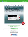
1
Europe Edition Electronic Test & Measurement Instruments, Power Supplies KIKUSUI PRODUCTS CATALOGUE 2013/2014 www.kikusui-europe.com To be a global company contributing to our customer's manufacturing base with our creative technology and quality. Electronic test and measuring instruments and power supplies are often called the "mother tools" of the industry. They are mandatory equipment for research, development and manufacturing premises, which are supporting the basis of electronics technology. KIKUSUI Electronics Corp. has been engaged in providing high-quality products as a specialized producer. In addition, we continue to strive to fulfill exact requirements for professionals and also to provide our original products in a timely manner with our "customercentered" and "environment-considered" philosophy. Moreover, KIKUSUI Electronics Corp. is now executing plans for globalization. Globalization of corporate activities has been our management theme, and today, the "global view" is critical to activities in worldwide environmental issues. Therefore, we would like to take a progressive approach to overseas projects in the future from the global point of view. Our company's motto is "Be a person having a deep love, who is neat and clean like KIKU (chrysanthemum) and is flexible like Mizu (water, another way of reading, SUI ) to go through everywhere." We understand the terms that "neat and clean" and "flexible" stand for a good faith and dedication as a specialized producer with a global view, and to act always on our customers' behalf. "To promote expertise in measurement and power supplies and to be a global company contributing to our customers' manufacturing base with our creative technology and quality." It is that to look to the future with aspirations. Company Profile Corporate name Kikusui Electronics Corp. Founded and Incorporated August 8, 1951 Capital 2,201 million yen President & C.E.O K. Kobayashi Main activities Manufacture, sale, and export & import of electronic test and measuring instruments, power supplies and software. Head Quarters & Engineering Centre Headquarters 1-1-3, Higashiyamata,Tsuzuki-ku, Yokohama, 224-0023, Japan Affiliate companies Fujitek Corp. (Japan) Kikusui Trading (Shanghai) Co., Ltd. (China) Kikusui America, Inc. (U.S.A) Main customers Self-Defense Force Agency / Ministry of Education, Culture, Sports, Science and Technology / Japan Atomic Energy Research Institute / Nippon Telegraph and Telephone Corp. / Hitachi, Ltd. / Toshiba Corp. / Mitsubishi Electric Corp. / NEC Corp. / Fujitsu Ltd. / Panasonic Corp. / Sony Corp. / Sanyo Electric Co., Ltd. / Pioneer Electric Corp. / Kyocera Corp. / ALPS Electric Co., Ltd. / Murata Manufacturing Co., Ltd. / Toyota Co., Ltd. / Denso Corp. / Nissan Motor Car Co., Ltd. / Honda Fuji-Katsuyama Factory Motor Co., Ltd. Main products Power Supplies, Electronic Loads, Tele-communication Measuring Instruments, Withstanding Voltage Testers, Insulation Testers, Earth Continuity Tester, Calibrators, Signal Generators History 1950s 1960s 1970s 1980s 1951 Kikusui Denpa established. 1962 Corporate name changed to Kikusui Electronics Corporation 1983 Fuji Katsuyama Factory established. 1986 Fujitec Co., Ltd. established as an affiliated factory of the Fuji Katsuyama Factory. 1988 Concluded exclusive agent contract with Marconi Instruments Ltd. (presently Aeroflex Incorporated), U.K. COM3000 Series Oscilloscope becomes the first category winner of the Good 1990s Design Award by MITI (Ministry of International Trade and Industry) 1991 Capital increased to 2,201,250,000 yen. Stock listed on domestic stock exchanges (November 22) 1993 Head office moved to Yokohama. 1994 Construction of Engineering Centre completed. 1995 ISO9001 certified by JQA. 1997 Construction of Head office. 2000 ISO14001 certified by JQA. 2000s 2004 Kikusui Electronics (Suzhou) Co.,Ltd. established in China. Kikusui America, Inc. established in the United States. 2006 Kikusui Trading (Shanghai) Co.,Ltd. established in China. www.kikusui-europe.com 3 I n t e r n e t KIKUSUI WEB www.kikusui-europe.com We, Kikusui Electronics Corporation, would like to offer you as much as information through our Kikusui Web including about Company Profile of Kikusui, Full line of Kikusui products, Overseas distributors, Services, New technologies and Introduction of latest products. We also uploaded for your convenience some of popular Instrument Drivers, which can be used with Lab VIEW or Visual Basic as Download Service. Electronic Catalogues in PDF format are also available for each product through our Web for more detailed specification and quality printing. 4 www.kikusui-europe.com CONTENTS Index & Selection 6 CE Marking Product List 12 DC Power Supplies 14 Power Supply Controllers 30 AC Power Supplies 34 Electronic Loads 40 Fuel Cell Impedance Meters 60 Battery Test System 64 Safety Testers 70 Measuring Instruments 102 Software 109 NOTE : * All products contained in this catalogue are equipment and devices that are premised on use under the supervision of qualified personnel, and are not designed or produced for home-use or use by general consumers. * Specifications, design and so forth are subject to change without prior notice to improve the quality. * Product names and prices are subject to change and production may be discontinued when necessary. * Product names, company names and brand names contained in this catalogue represent the respective registered trade name or trade mark. * Colors, textures and so forth of photographs shown in this catalogue may differ from actual products due to a limited fidelity in printing. * Although every effort has been made to provide the information as accurate as possible for this catalogue, certain details have unavoidably been omitted due to limitations in space. * If you find any misprints or errors in this catalogue, it would be appreciated if you would inform us. * Please contact us to confirm specifications, price, accessories or anything that may be unclear when placing an order or concluding a purchasing agreement. NOTE : Markings Rack Assemblies 110 NEW Identifies new products appearing in this years catalog. COMING SOON GPIB RS-232C USB Products equipped with these interfaces as standard. GPIB RS-232C USB OPTION OPTION OPTION Products optionally available with these interfaces. Products supporting instrument drivers for VisualBasic, LabVIEW, LabWindows/CVI and IVI-COM. Refer to the down load service for drivers at Kikusui Web site. CE marked products LXI(LAN eXtention for Instrumentation) LXI is a type of interface standard extended to an instrumentation platform based on industry standard Ethernet (LAN) technology. The LXI Consortium is an industry consortium with over 50 of the top T&M companies such as Agilent Technology, VXI Technology sponsoring and developing this technology. (We, Kikusui Electronics Corp, are also a member of this consorthium) www.kikusui-europe.com 5 INDEX 2 E KRB6............................... 112 OT02-KPM. .....................106 2P05-PCR-LE. ................. 35 EC05-PCR. ...................... 36 KRB9............................... 112 P 3 ET-11................................. 17 KRB100-TOS....... 60, 62, 101 PAN16-10A.......... 24, 25, 116 3P05-PCR-LE.................. 35 EX04-PCR-M. ............ 38, 39 KRB150........................... 112 PAN16-18A.......... 24, 25, 116 4 EX05-PCR-LE.................. 35 KRB150-PLZ-30F............ 112 PAN16-30A.......... 24, 25, 116 408J-101. ......................... 30 EX06-PCR-LE.................. 35 KRB150-PLZ-50F............ 112 PAN35-5A........... 24, 25, 116 408J-102. ......................... 30 F KRB150-TOS............101, 112 PAN35-10A.......... 24, 25, 116 408J-104. ......................... 30 FGA5050................. 104, 105 KRB200........................... 112 PAN35-20A. ........ 24, 25, 116 A FGA5050GC. .......... 104, 105 KRB400-PCR-LE............ 112 PAN60-3A........... 24, 25, 116 AC1-3P2R5M-IEC320-EU. .. 20 FP01-TOS........................100 KRC273........................... 110 PAN60-6A........... 24, 25, 116 AC5.5-3P3M-M4C............ 35 H KRC273L......................... 110 PAN60-10A.......... 24, 25, 116 AC8-1P3M-M5C-3S. ........ 35 HP01A-TOS.....................100 KRC363. ......................... 110 PAS10-35............. 17, 19, 114 AC14-1P3M-M8C-3S........ 35 HP02A-TOS. ...................100 KRC363L. ....................... 110 PAS10-70.............. 17, 19, 114 AC14-1P3M-M5C-4S........ 35 HP11-TOS........................100 KRC1203......................... 110 PAS10-105............ 17, 19, 114 AC22-1P3M-M8C-3S. ...... 35 HP21-TOS.......................100 KRC1203L....................... 110 PAS20-18. ............ 17, 19, 114 B HTL-2.5DH. .....................100 KRC1603......................... 110 PAS20-36............. 17, 19, 114 B22.................................. 112 I KRC1603L....................... 110 PAS20-54............. 17, 19, 114 B2-PIA4810/4820............ 112 IB05-PCR-LE................... 35 KRO900.......................... 110 PAS40-9............... 17, 19, 114 B42.................................. 112 IB21............................ 38, 39 KRO1250......................... 110 PAS40-18. ............ 17, 19, 114 BP191-M.......................... 112 K KRO1600......................... 110 PAS40-27............. 17, 19, 114 BP1H-M........................... 112 KFM2005. ...................60, 61 L PAS60-6............... 17, 19, 114 BZ01-TOS........................ 101 KFM2030. .................. 62, 63 LC01-PCR-LE................... 35 PAS60-12. ............ 17, 19, 114 C KPM1000................. 106, 107 LN05-PCR-LE.................. 35 PAS60-18. ............ 17, 19, 114 CC01-PCR-LE.................. 35 KRA2...............................106 LP01-TOS........................100 PAS80-4.5............ 17, 19, 114 CC02-PCR-LE.................. 35 KRA3........................ 111, 112 LP02-TOS........................100 PAS80-9............... 17, 19, 114 CH01-PWR........................15 KRA3-TOS. ..................... 101 O PAS80-13.5. ......... 17, 19, 114 D KRA4-TOS. ..................... 101 OP01-KRC. ..................... 110 PAS160-2............. 17, 19, 114 DD-3 5P. ......................... 101 KRA100...........................106 OP02-KRC...................... 110 PAS160-4............. 17, 19, 114 DD-5P/6P........................ 101 KRA150.................... 111, 112 OP03-KRC...................... 110 PAS160-6............. 17, 19, 114 DME1600. ............... 102, 103 KRA150-TOS................... 101 OP04-KRC...................... 110 PAS320-1............. 17, 19, 114 DME1600GC........... 102, 103 KRA200-TOS.................. 101 OP01-PAS................... 15, 17 PAS320-2............. 17, 19, 114 DME1600-OPT01............102 KRA300-TOS. ................. 112 OP01-PFX.................. 64, 65 PAS320-3............. 17, 19, 114 DME1600-OPT02............102 KRB2-TOS........... 60, 62, 101 OP01-PIA. .........................31 PAS500-0.6.......... 17, 19, 114 DME1600-OPT07............102 KRB3............................... 112 OP01-PLZ-4W............ 42, 49 PAS500-1.2.......... 17, 19, 114 DME1600-OPT08............102 KRB3-PLZ-30F................ 112 OP02-PIA..........................31 PAS500-1.8. ......... 17, 19, 114 DME1600-OPT09............102 KRB3-PLZ-50F................ 112 OT01-KPM.......................106 PBZ20-20............ 26, 28, 115 DME1600-OPT11............102 KRB3-TOS. ..............101, 112 OT01-TOS. ...................... 101 PBZ40-10. ........... 26, 28, 115 DME1600-OPT12............102 KRB4............................... 112 OT01-PBZ. ....................... 27 PC01-PCZ1000A.............. 58 6 www.kikusui-europe.com INDEX PC01-PLZ-4W. ......42, 49, 52 PLZ164WA.......... 41, 43, 119 S TL44................................106 PC01-PWX....................... 20 PLZ164WH..........48, 50, 120 SC01-10............................ 30 TL45................................106 PC02-PLZ-4W.......42, 49, 52 PLZ334W............ 41, 43, 119 SC01-20. .......................... 30 TOS3200.................... 98, 99 PC02-PWX....................... 20 PLZ334WL.......... 46, 47, 120 SC03-PIA......................... 30 TOS5050A. ................ 89, 90 PC03-PWX....................... 20 PLZ334WH..........48, 50, 120 SC04-PIA......................... 30 TOS5051A.................. 89, 90 PCR500LE.......... 34, 36, 118 PLZ664WA.......... 41, 43, 119 SC05-PIA......................... 30 TOS5101. ................... 82, 83 PCR500M. .......... 38, 39, 117 PLZ1004WH........48, 50, 120 SD002.............................. 66 TOS5300.................... 84, 86 PCR1000LE. ....... 34, 36, 118 PLZ2004WB..................... 42 SD004-TOS5000A.... 89, 101 TOS5301.................... 84, 86 PCR1000M.......... 38, 39, 117 PLZ2004WHB........... 49, 120 SD009-PCR-LE................ 35 TOS5302.................... 84, 86 PCR2000LE........ 34, 36, 118 PLZ70UA............. 52, 54, 117 SD014-PBZ....................... 27 TOS6200.....................94, 97 PCR2000M. ........ 38, 39, 117 PMR18-1.3TR...... 22, 23, 115 SH10. ............................... 30 TOS6210.................... 94, 95 PCR3000LE........ 34, 36, 118 PMR18-2.5DU..... 22, 23, 115 SH50................................ 30 TOS7200..................... 91, 92 PCR4000LE........ 34, 36, 118 PMR24-1QU........ 22, 23, 115 T TOS9200.................... 72, 77 PCR6000LE........ 34, 36, 118 PMR25-1TR......... 22, 23, 115 TL01-PLZ. ........................ 46 TOS9201.................... 72, 77 PCR9000LE........ 34, 36, 118 PMR35-1.2DU..... 22, 23, 115 TL01-TOS........................100 TOS9213S...................75, 81 PCZ1000A........... 58, 59, 119 PWR400H........... 14, 16, 113 TL02-PLZ......................... 46 TOS9220.................... 76, 80 PD05M-PCR-LE............... 35 PWR800H........... 14, 16, 113 TL02-PFX......................... 66 TOS9221.................... 76, 80 PD05S-PCR-LE. .............. 35 PWR1600H. ........ 14, 16, 113 TL02-TOS........................100 TU02-PIA. ........................ 30 PFX2011..................... 66, 68 PWR400L............ 14, 16, 113 TL03-PLZ......................... 46 U PFX2021.................... 66, 68 PWR800L............ 14, 16, 113 TL03-TOS........................100 US05-PCR-LE.................. 35 PFX2121. ......................... 66 PWR1600L.......... 14, 16, 113 TL04-PFX......................... 66 US21.......................... 38, 39 PFX2211........................... 66 PWR400M........... 14, 16, 113 TL04-TOS........................100 V PFX2332.......................... 66 PWR800M........... 14, 16, 113 TL05-PFX......................... 66 VS01................................. 27 PFX2511..................... 64, 65 PWR1600M......... 14, 16, 113 TL05-TOS........................100 W PIA4810............................ 30 PWX750HF...................... 20 TL06-PFX......................... 66 Wavy for PAS&PWR... 15, 17, 109 PIA4820. .......................... 30 PWX750LF....................... 20 TL06-TOS........................100 Wavy for PBZ............ 27, 109 PIA4830. .......................... 30 PWX750MHF................... 20 TL07-PFX......................... 66 Wavy for PCR-LE......35, 109 PIA4850. .......................... 32 PWX750MLF.................... 20 TL07-TOS........................100 Wavy for PCR-M.......38, 109 PK01-PBZ......................... 27 PWX1500H....................... 20 TL08-PFX......................... 64 Wavy for PCZ1000A...58, 109 PK02-PBZ. ....................... 27 PWX1500L....................... 20 TL08-TOS........................100 Wavy for PLZ-4W. .42, 46, 49, 109 PK03-PBZ........................ 27 PWX1500MH.................... 20 TL09-PFX......................... 64 Wavy for PLZ-U.........52, 109 PL01-TOS........................ 101 PWX1500ML.................... 20 TL11-TOS.........................100 Wavy for PWX...........20, 109 PL02-TOS........................ 101 R TL12-TOS. .......................100 PLZ-30F. ..............52, 57, 117 RC01-TOS....................... 101 TL21-TOS........................100 PLZ-50F. ..............52, 57, 117 RC02-TOS....................... 101 TL40................................106 PLZ1004W. ......... 41, 43, 119 RD-8P/9P......................... 20 TL41................................106 PLZ150U............. 52, 54, 117 RMF4. ...................... 111, 112 TL42................................106 PLZ164W. ........... 41, 43, 119 RMF4M. ................... 111, 112 TL43................................106 www.kikusui-europe.com 7 Selection DC Power Supply Multi Range DC Power Supply (CV/CC) PWR Series Three types of wide-range power supplies covering 80 V to 650 V SWITCHING SYSTEM GPIB/ RS-232C OPTION USB OPTION P.14 Dual-tracking DC Power Supply (CV/CC) PMR Series A multi-output system in a simple way with TP-BUS Variable-switching Regulated DC Power Supply (CV/CC) 1U Multi Range Programmable DC Power Suppy PAS Series PWX Series Equipped with digital communication functions and a power-factor correction circuit. SWITCHING SYSTEM GPIB/ RS-232C OPTION USB OPTION P.17 High Reliability DC Power Supply (CV/CC) GPIB/ RS-232C OPTION USB OPTION PAN-A Series Basic DC power supplies superior for general purpose use. COMING SOON New standard of rack mount power supply USB RS-232C LAN SWITCHING SYSTEM P.20 Programmable Bipolar Power Supply (CV/CC) GPIB/ RS-232C OPTION PBZ Series Superior output characteristic by adopting the power amp system GPIB/ RS-232C USB LAN OPTION * While Supplies Last LINEAR (SERIES REGULATOR) SYSTEM P.22 LINEAR (SERIES REGULATOR) SYSTEM P.24 Power Supply Controller Power Supply Controller PIA4800 Series Power Supply Controller GPIB/ RS-232C Supporting multiple channels PIA4850 USB Digital control of DC power by USB! P.30 P.32 AC Power Supply High-performance Multifunctional AC Power Supply (CV/CF) Compact AC Power Supply (CV/CF) PCR-LE Series PCR-M Series New stage of AC power supply supporting new energy field GPIB/USB OPTION RS-232C Compact AC power supply using the PWM inverter method GPIB/USB OPTION RS-232C LAN OPTION LINEAR SYSTEM 8 www.kikusui-europe.com P.34 SWITCHING SYSTEM P.38 P.26 Electronic Load Multifunctional Electronic Load (CC/CV/CR/CP) PLZ-4W Series Suitable design for fuel cell, faster speed and lower voltage testing application of various devices! Multifunctional Electronic Load (CC/CV/CR/CP) GPIB/ RS-232C USB PLZ-4WL Series High speed-large current DC electronic load (50 A/μs) P.41 Electronic Load (AC) PLZ-U Series PCZ1000A Multi-channel load systems can be built easily! Operating multiple units in parallel offers large capacity! USB PLZ-4WH Series GPIB/ RS-232C High-voltage electronic load 650 V! For EV and HEV high-voltage converters. With the booster, extended capacity at a low cost can be realized! USB P.46 Modular Multifunction Electronic Load (CC/CV/CR/CC+CV/CR+CV) GPIB/ RS-232C Multifunctional Electronic Load (CC/CV/CR/CP) GPIB/ RS-232C P.48 RS-232C For load test of inverters or transformers used for Fuel Cell, UPS, or Solar power generation P.52 P.58 Fuel Cell Impedance Meter Fuel Cell Impedance Meter KFM2005 Possible to acquire the Tafel plot and the cole-cole plot of the micro fuel cell Fuel Cell Impedance Meter GPIB/ RS-232C USB KFM2030 Fuel cell characteristic, variation, and service life testing can be done with ease! P.60 GPIB/ RS-232C USB P.62 Battery Test System Battery Test System PFX2511 Battery Test System USB Fully support charge and discharge measurement from basic test to simulation test PFX2000 Series USB Implementing sophisticated battery tests with ease. A highly flexible system can be built P.64 P.66 www.kikusui-europe.com 9 Selection Safety Tester Hipot Tester with Insulation Resistance Tester TOS9200/9201 Hipot Tester with Insulation Resistance Test GPIB/ RS-232C Perfect design for system operation, introducing our top of the line of Hipot /Insulation Resistance testers TOS9213S Suitable for the insulation testing of PV module P.72 Hipot Tester(AC/DC) TOS5101 TOS5300 Series A new standard for Hipot & Insulation Resistance testing applied to world-wide input voltage P.82 RS-232C TOS7200 Pursuing to maximize an easy operation, stylish design of Ground Bond tester www.kikusui-europe.com TOS3200 P.89 TOS6210 GPIB/ RS-232C Supports UL60950-1 - new standard for Information Technology Equipment (ITE) P.91 Complying with various safety standards for general electrical equipment, this tester is used for touch current and protective conductor current tests!! P.94 10 RS-232C Leakage Current Tester GPIB/ RS-232C RS-232C Ground Bond Tester Complied with the test voltage -25 V to -1000 Vdc of the JIS C 1302-2002 Ground Bond Tester TOS5051A Capable to record and storage of the test data AC/DC Output 5 kV type P.84 P.89 TOS6200 USB Insulation Resistance Tester Capable to record and storage of the test data P.76 Hipot Tester(AC/DC) Hipot Tester with Insulation Resistance Tester Hipot Tester(AC) TOS9220/9221 Extended features of TOS9200/9201 for multi-channel testing application P.75 High-end model of TOS series having AC, DC10 kV output TOS5050A High-voltage scanner GPIB/ RS-232C GPIB/ RS-232C USB P.98 P.94 Measuring Instruments Multifunctional Electronic Load (CC/CV/CR/CP) DME1600 6 1/2 digit resolution, essential device of “Electronic Measurement” supporting basic measurement with variety of options Function Generator GPIB DME1600GC USB P.102 FGA5050 50 MHz arbitrary waveform generator The LXI interface makes easier for the test system! Digital Power Meter GPIB FGA5050GC USB LAN P.104 KPM1000 GPIB/USB Applies to the power measurement from the micro scale to the large scale!! OPTION RS-232C P.106 Software Application Software for Power Supplies and Electronic Loads WAVY Easy-to-operate software expanding functions of power supplies and electronic loading units P.109 www.kikusui-europe.com 11 CE MARKING PRODUCT LIST APPLICABLE MODELS FOR MARKING DC Power Supply Series Model PWR Series PAS Series PMR Series all models all models all models PAN16-10A PAN16-18A PAN16-30A PAN35-5A PAN35-10A PAN35-20A PAN60-3A PAN60-6A PAN60-10A all models PAN-A Series PBZ Series Safety Tester Reference page 14 17 22 24 24 24 24 24 24 24 24 24 26 *1 *1 *1 *3 *3 *3 *3 *3 *3 *3 *3 *3 Power Supply Controller Series Model PIA Series PIA4810 PIA4820 PIA4830 PIA4850 Series Model TOS Series TOS9200/9201 TOS9213S TOS9220/9221 TOS5101 TOS5300 TOS5301 TOS5302 TOS5051A TOS5050A TOS7200 TOS6210 TOS6200 TOS3200 Reference page 30 30 30 32 Series *1 *1 *1 *1 AC Power Supply Model PCR-LE Series PCR-M Series all models all models DME1600 FGA5050 34 38 Model PLZ-4W Series PLZ-4WL Series PLZ-4WH Series PLZ-U Series PCZ1000A all models PLZ334WL all models all models PCZ1000A *1 *1 Reference page 41 46 48 52 58 *1 *1 *1 *1 *1 Fuel Cell Impedance Meter Series Model KFM Series KFM2005 KFM2030 Reference page 60 62 *1 *1 Model TU02-PIA OP01-PIA OP02-PIA TL01-TOS TL02-TOS TL03-TOS TL04-TOS TL05-TOS TL06-TOS TL07-TOS TL08-TOS TL11-TOS TL12-TOS RC01-TOS Battery Test System Series Model PFX2500 Series PFX2000 Series PFX2511 all models Reference page 64 66 *1 *1 ORDERING INFORMATION *1.CE Marked model is available at all standard Input voltage as specified in each specification. *2.CE Marked model is available only for the unit equipped with Input voltage of 210 V to 250 V. *3.CE Marked model is available only for the unit equipped with Input voltage of 230 VAC. * Please indicate ‘CE Marked Products’ when ordering or request for the quote. 12 www.kikusui-europe.com Model Reference page DME1600 DME1600GC FGA5050 FGA5050GC KPM1000 102 102 104 104 106 Option Reference page Electronic Load Series 72 75 76 82 84 84 84 89 89 91 94 94 98 Measuring Instruments KPM1000 Series Reference page Reference page 30 31 31 100 100 100 100 100 100 100 100 100 100 100 *1 *1 *1 *3 *1 *1 *1 *3 *3 *1 *1 *1 *1 www.kikusui-europe.com 13 DC POWER SUPPLY SWITCHING SYS TEM Three types of Wide-Range Power Supplies Covering 80 V to 650 V Multi Range DC Power Supply (CV/CC) PWR Series GPIB RS-232C USB OPTION OPTION OPTION The PWR Series offers constant voltage (CV)/constant current (CC) automatic crossover DC power supplies that enable you to combine a wide range of voltages and currents within the output power rating. For example, the model that has an output power rating of 1600 W (PWR1600L) provides a seamless operation range from 80 V - 20 A to 16 V - 100 A. With a single PWR Series power supply alone, you can cover an extensive output range equivalent to what is provided by three to six conventional single range DC power supplies. L type can output up to 160 % of the output current rating (in the continuous and intermittent extended operation areas). PWR1600L supports a maximum output of 10 V - 160 A. TYPE II (800W TYPE) TYPE III (1600W TYPE) TYPE I (400W TYPE) Dimensions / Weight Type I :106.5(4.19˝)W ✕ 124(4.88˝)H ✕ 400(15.75˝)Dmm / 5kg(11.02 Ibs.) Type II :214(8.43˝)W ✕ 124(4.88˝)H ✕ 400(15.75˝)Dmm / 8kg(17.64 Ibs.) Type III :428.5(16.87˝)W ✕ 128(5.04˝)H ✕ 400(15.75˝)Dmm / 15kg(33.07 Ibs.) Accessories Operation manual, TP-BUS connector, Output terminal screws (M4, M8), Output protection cover Type I :2.4 m power supply cable with 3-pin plug Type II :3 m power supply cable with 3-pin plug Type III :3 m power supply cable with no plug, Cable clamp Functions ■Seamless five times variable voltage/current range (Note: For H type, 3.25-time variable voltage/current range) A single PWR Series power supply supports an extensive operation range, covering an output range equivalent to what is provided by several conventional single range DC power supplies. Also, the maximum output powers of the power supplies of this series are 400 W, 800 W, and 1600 W - slightly higher than those of their predecessors. You can conduct tests without worrying about power limits. ■Best for testing a wide variety of high-voltage devices including margin tests The maximum output voltage of L type is 80 V. For example, 150 % of 42 V (63 V) can be supplied for testing vehicular electrical components, or 150 % of 48 V (72 V) can be supplied for testing communication equipment. In addition, the M type (320 V) is suitable for checking designs of energy-saving circuits for flat display panels and the development of new materials, while the H type (650 V) can be used to test various components and devices that use high voltages such as automotive devices, photovoltaic inverters, and many more. ■Two extended operation areas where up to 160 % of the output current rating can be output (L type only) In the extended operation areas, the power supply can output up to 160% of the output current rating. This feature is convenient when testing an automobile motor or other load device that requires high current at startup time. Since the power supply can output continuous current up to 120 % of the output current rating with the restricted ambient temperature range and current up to 160 % of the output current rating with the restricted output time tests can be conducted with a power capacity one rank lower. This feature also helps you cut equipment costs and save floor space. 14 www.kikusui-europe.com Features ■Supports a digital communication function (TP-BUS) as standard. ■Analog external control functions are available, providing voltageand resistance-based output voltage and current controls. ■Comes standard with the remote monitoring function. External analog monitoring can be done with respect to the output voltage, output current, and operation mode. ■A built-in power factor correction circuit (with power factor 0.98) for harmonic current suppression, as well as a highly efficient switching circuit (efficiency 70 %). ■A four-digit display can display the voltage, current, and power (W). ■Front-side output terminals (up to 30 A) for desktop use. ■A universal AC input supports a range of voltages from 100 V to 240 V. ■Parallel or serial operation Parallel operation enables multiple power supplies of the same model to operate in parallel, offering a large capacity of up to 8 kW (when five 1600-watt models are connected in parallel). In a serial operation, the voltage can be increased up to 160 V. (Note:• Parallel and serial operations cannot be done at the same time. • Serial operations are not possible for the M and H types.) ■Up to 32 PWR Series power supplies can be controlled with one GPIB address The PWR Series supports a digital communication function (TP-BUS) as its standard feature. When used with a power supply controller (PIA4850) to be purchased separately, the function enables up to 32 PWR Series power supplies to be controlled using USB interface. In addition, the sequence generation software (Wavy for PAS & PWR), also to be purchased separately, allows even those users who have no knowledge of any programming language to exert output control over the PWR Series power supplies with sequence patterns of their choice and to read resultant data through the use of a PC. (Note:For controlling via GPIB or RS-232C, please use PIA4830.) PWR series USB PIA4850 TPBUS PWR series TPBUS PWR series TPBUS Up to 32 PWR series power supplies can be controlled 200m *For the details, please refer to page 32 . SWITCHING SYS TEM Note: The ambient temperature and output time are restricted in the extended operation areas. L type: 0 V to 80 V Rated output voltage 80 Rated output power line 50 16 10 0 Rated operation range M type: 0 V to 320 V 5 times variable range (8 times variable range at max. output current) Rated output Continuous extended operation areas current Intermittent extended operation areas Maximum output current Output voltage [V] Output voltage [V] 100 Rated output power line 20 25 30 40 50 10 20 40 50 60 80 100 20 40 80 100 120 PWR400L PWR800L PWR1600L 160 200 Output current [A] 3.25 times variable range Rated output voltage 650 Rated output power line Rated output current Rated output current 200 64 5 10 Rated output voltage 320 H type: 0 V to 650 V 5 times variable range Output voltage [V] Operation Area DC POWER SUPPLY 0 1.25 6.25 2.5 12.5 5 PWR400M PWR800M PWR1600M 25 Output current [A] 0 0.615 1.23 2.46 2 4 PWR400H PWR800H PWR1600H 8 Output current [A] Options ■Accessory Kit OP01-PAS ■Carrying Handle (for 400 W model) CH01-PWR ■Sequence Creation Software Wavy for PAS & PWR (used for the connection of J1 connector on the rear panel when operating by external control) ● Connector, Semi-cover, Pin 10 pcs., Ground cable [NOTICE] Because a noise filter is used for the primary input for the PWR Series, the leakage breaker, etc. may be activated, depending on the environment of the input power, when using multiple quantities of them at the same time. Therefore, we provide models for customers who are planning to use multiple devices at the same time. If you have any other questions, please contact our sales department for details. www.kikusui-europe.com 15 DC POWER SUPPLY PWR Series Specifications Output Model PWR400L L type PWR800L PWR1600L CV CC V A W PWR800M 0~320 PWR1600M PWR400H H type PWR800H 0~650 PWR1600H Transient Load regulation response Constant current (CC) characteristics Power input/Miscellaneous Ripple Line regulation Load Input current regulation Inrush current Weight ms mArms 0.1 % + mA 0.1 %+mA AC (100/200 V) A Apeak (Max) kg (approx.) 5 1 40 10 10 6.5/3.3 35 5 3 5 1.5 80 10 10 13.0/6.5 70 8 20 3 5 2 160 10 10 26.0/13.0 140 15 Ripple Line regulation mVrms 0.05 % + mV 0.05 % + mV 10 3 15 0~25 400 MAX 40* 0~50 0~80 800 MAX 80* 0~100 1600 MAX 160* PWR400M M type Constant voltage (CV) characteristics Rated power 0~6.25 400 15 3 5 4 25 10 10 6.25/3.13 35 5 0~12.5 800 20 3 5 8 35 10 10 12.5/6.25 70 8 0~25 1600 25 3 5 12 50 10 10 25.0/12.5 140 15 0~2 400 20 3 5 6 10 10 10 6.0/3.0 35 5 0~4 800 30 3 5 7 20 10 10 12.0/6.0 70 8 0~8 1600 40 3 5 8 40 10 10 24.0/12.0 140 15 *The L type offers extended operation areas equivalent to up to 160 % of the output current rating. Some of the specifications may not be satisfied in the extended operation areas. •Continuous extended operation area (up to 120 % of the output current rating): Continuous current output is enabled. However, derating occurs at an ambient temperature 30 ˚C or higher. •Intermittent extended operation area (120 % to 160 % of the output current rating): Continuous current output is enabled for 10 minutes or less. However, a nonoperating period more than twice the output period must be taken. ■ Input power����������� 100 to 240 VAC (85 to 250 VAC), single-phase 50 to 60 Hz (47 to 63 Hz) ■ Power factor���������� 0.98 standard ■ Efficiency�������������� 70 % or greater ■ Temperature��������� 100 ppm/˚C for constant voltage output coefficient 200 ppm/˚C for constant current output ■ Measuring meters ● Voltmeter������������ Maximum display (fixed point): 99.99 (L type), 999.9 (M and H types) (23 ˚C ±5 ˚C) Display error: ±(0.2 % of rdg* + 5 digits)* rdg = reading ● Ammeter��������������Maximum display (fixed point) (23 ˚C ±5 ˚C) Maximum output current Maximum display digits Models supporting 10 A or less 9.999 Models supporting 10 to less than 100 A 99.99 Models supporting 100 A or greater 999.9 Display error: ±(0.5 % of rdg* + 5 digits)* rdg = reading function.... ● Over voltage protection (OVP): Setting range (10 % to 110 % of the rated output voltage) ● Over current protection (OCP): Setting range: (10 % to 110 % of the rated output current) for the M and H types Setting range: (10 % to 176 % of the rated output current) for the L type ● Over power protection (OPP): Approx. 110 % of the rated output power or greater ● Over heat protection (OHP): Operates due to an internal temperature rise. ● Power limit (POWER LIMIT): Power limit imposed at approx. 105 % of the rated output power. ■ Parallel operation... Up to 5 units including master (of same model) ■ Serial operation..... Up to 2 units including master (of same model, for the L type only) ■ Digital control......... TP-BUS (directly controllable from PIA4810/PIA4830) ■ Monitor signal output��� VMON (at rated voltage output), IMON (at maximum current output): 10.00 ±0.25 V ■ Status signal output.... OUT ON/CV/CC/ALM/PWR OFF/PWR ON ■ Protection 16 www.kikusui-europe.com ■ Environmental ...... Operating ambient temperature range: 0 ˚C to + 50 ˚C Derating occurs on output current at 45 ˚C or higher for the L type and 40 ˚C or higher for the M/H types. ● Operating ambient humidity range: 20 % to 85 %rh (non-condensing) ● Storage temperature range: -25 ˚C to +70 ˚C ● Storage humidity range: 90 %rh or less (non-condensing) ■ Cooling system...... Forced air cooling (thermal control: Fan control function attached) ■ Ground polarity...... Negative or positive ground polarity possible. ■ Ground voltage...... ±600 Vmax for the L and M types ±1000 Vmax for the H type ■ Electromagnetic . .. Conformance to the requirements of the directives and compatibility standards below. EMC Directive 89/336/EEC EN61326: 1997/A2 : 2001 Emission: Class A Immunity: Minimum immunity test requirements EN61000-3-2: 2000 EN61000-3-3: 1995/A1: 2001 *Not applicable to custom-made modified products. *Only those models with CE marking provided on their panel. ■ Safety.................... Conformance to the requirements of the directive and standard below. Low Voltage Directive 73/23/EEC EN61010-1: 2001 Class I, Overvoltage Category II, Pollution Degree 2 ■ Dimensions............ 400-watt type: 106.5 W × 124 (145) H × 400 (470) D mm 800-watt type: 214 W × 124 (155) H × 400 (470) D mm 1600-watt type: 428.5 (450) W × 128 (150) H × 400 (470) D mm *Enclosed in parentheses are maximum dimensions. ■ Accessories���������� ● Instruction manual ● Power cord (400-watt type: Approx. 2.4 m in length, with a plug 800-watt type: Approx. 3 m in length, with a plug 1600-watt type: 3 m in length, without a plug) ● Rear side output terminal protection cover ● TP-BUS connector ● J1 dummy connector ● Output terminal screws etc. conditions SWITCHING SYS TEM Variable-switching Regulated DC Power Supply (CV/CC) PAS Series GPIB RS-232C USB OPTION OPTION OPTION TYPE I (350 W TYPE) TYPE II (700 W TYPE) TYPE III (1000 W TYPE) Dimensions / Weight Type I :71(2.8˝)W ✕ 124(4.88˝)H ✕ 350(13.78˝)Dmm / 3kg(6.61 Ibs.) Type II :142.5(5.61˝)W ✕ 124(4.88˝)H ✕ 350(13.78˝)Dmm / 5kg(11.02 Ibs.) Type III :214(8.43˝)W ✕ 124(4.88˝)H ✕ 350(13.78˝)Dmm / 7kg(15.43 Ibs.) Accessories Operation manual, power cord (350 W/700 W TYPES: approx. 2.4 m long, with 3 P plug/1000 W TYPE: approx. 3 m long, without plug), Rear output terminal protection cover, TP-BUS connector, J1 dummy plug for protection, Output terminal screws (M4/M8) DC POWER SUPPLY Equipped with digital communication functions and a power-factor correction circuit. The PAS Series consists of sophisticated variable-switching DC power supplies that refine and add to the advances of our conventional PAK-A Series. While the cabinet size remains unchanged from conventional models, the PAS Series incorporates a high-efficiency switching circuit and a power-factor correction circuit to meet the needs of today's users. Provided with Kikusui-developed digital communication functions (TPBUS: Twist Pair Bus) as standard equipment, this series can handle power supply systems ranging from small scale (two units) to large scale systems (up to 448 channels in combination with power supply controllers of the PIA4800 Series via GPIB) at low cost. The distance between the controller and power supplies can be extended up to 200 m for use in applications such as plant power supply control from the PC at office. Features ■Equipped with a power-factor correction circuit ■High power conversion efficiency of 75 %(TYP.) ■Equipped with digital communication functions ■Four-digit indication display unit ■Multifunction dial ■Supporting universal AC input Options ■Accessory Kit OP01-PAS ■Extended Terminal ET-11 (used for the connection of J1 connectoron the rear panel when operating by external control) ● Connector, Semi-cover, Pin 10 pcs., Ground cable ■Sequence Creation Software Wavy for PAS & PWR www.kikusui-europe.com 17 DC POWER SUPPLY SWITCHING SYS TEM Functions ■Attractive new design ■High-resolution meter displays power (W) The dynamic new color scheme of the PAS Series features a gray-white base with a front louver in vibrant blue. Models in this series are controlled with a multifunction dial and feature a high-brightness four-digit indication display unit. Display digits provide readings down to 10 mV/1 mA, and a output power (W) display function is also provided. The end result is improved operability and visibility. Four digits are used to display output voltage/current at the same time. The configurable digits are more brightly lit than the others, to ensure easy and safe verification/ operation. The output power is also displayed. You can set the output voltage/current while monitoring the output power [Voltmeter measurement accuracy: ± (0.2 % of rdg + 5 digits) ammeter measurement accuracy: ± (0.5 % of rdg + 5 digits)]. * The maximum number of digits displayed on the ammeter (i.e. the location of the ■Handling margin testing with capacity The maximum rated output voltage of conventional products is typically a range consisting of 6 V, 10 V, 20 V, 35 V, and 60 V. The PAS Series offers a maximum rated output voltage of 10 V, 20 V, 40 V, 60 V, 80 V, 160V, 320V, and 500V, in response to changes in the voltage ranges required for margin testing due to the conversion of equipment such as DC-DC converters, batteries, automobile electrical components, and motor-operated tools to high voltage or large capacity formats. This allows the PAS Series to handle tests at 150 % of 24 V (36 V) or at 150 % of 48 V (72 V) with capacity to spare. decimal point) varies according to the model. Maximum Output Current Model less than 10 A Model above 10 A less than 100 A Model above 100 A, PAS500-0.6 PAS500-1.2, PAS500-1.8 Maximum Display 9.999 99.99 999.9 9999 * Current value for 500 V models are displayed at the unit of (mA) ■External analog control functions ● Constant-voltage/constant-current output control function Output control based on external voltage (0 V to 10 V) Output control based on external resistance (0 W to 10 kW) ● Output ON/OFF control function External contact-based output ON/OFF control ● Power switch control function External contact-based power switch OFF control ■Analog read-back function ● Monitor output (voltage output) Output voltage monitoring Output current monitoring ● Status signal output (contact signal output) CV mode signal, CC mode signal, Output ON signal, Alarm signal, POWER ON signal ■High efficiency and high power factor The PAS Series employs a high-efficiency switching circuit that inherits its core circuit from the PAK-A Series, achieving a power conversion efficiency of 75 % (70 % or better for 10 V models). Models in the series incorporate a power-factor correction circuit with a power factor of 0.98 that suppresses higher harmonic currents. The PAS Series reduces power consumption cost, as well as heat-dissipation design cost, when the system is configured. ■Parallel and series operation For master/slave use, the PAS Series handles parallel (current expansion) and series (voltage expansion) operations. The maximum number of units that can be connected in series is two, while the maximum number of units connectable for parallel applications is five for the 350 W type, three for the 700 W type, and two for the 1000 W type. ■Universal mode available for AC input For AC input, a universal mode (continuous between 100 V and 240 V) is used instead of a 100 V/200 V switchover type. The AC power connector* (AC inlet) used ensures safe and easy connections. * Only with 350 W types and 700 W types. For 1,000 W types, a terminal block is used. ■Front-panel auxiliary output terminal A front-panel auxiliary output terminal helps you to remove outputs with ease. Please note, however, that an accident may result in the event of inadvertent user contact. Moreover, this terminal can use only a limited current. Thus, when a large amount of power is used, the maximum load can not be realized. To meet your needs, Kikusui offers the extended ET-11 terminal, available as a separate option. ■Digital communication function In addition to output control based on external voltage, external resistance, or contact signal (so-called external analog inputs), the PAS Series offers a digital remote control read-back function (TP-BUS: Twisted Pair Bus) as standard equipment. This TP-BUS enables a single power supply controller (PIA4850) to control up to 32 PAS Series units. (Note:For controlling via GPIB or RS-232C, please use PIA4830.) ● Example of connection using TP-BUS PAS series USB PIA4850 TPBUS PAS series TPBUS PAS series TPBUS Allows control of up to 32 power supplies. 200 m *For the details, please refer to page 32 . * The same model types must be used for a given operation. The units cannot be connected in series and parallel simultaneously. 320 V model and 500 V model can not be connected in Series configuration. [NOTICE] Because a noise filter is used for the primary input for the PAS Series, the leakage breaker, etc. may be activated, depending on the environment of the input power, when using multiple quantities of them at the same time. Therefore, we provide models for customers who are planning to use multiple devices at the same time. If you have any other questions, please contact our sales department for details. 18 www.kikusui-europe.com DC POWER SUPPLY PAS Series Specifications Output Model Constant Voltage CV CC Ripple V A mV rms Line Load regulation regulation Constant Current Transient response Ripple ms mV or less mV or less (typical value) mA rms Other Line Load regulation regulation Input current Rush current AC Ap to mA or less mA or less (100 V/200 V)A peak(Max) External dimensions Weight TYPE kg (approx.) PAS10-35 0 to 10 0 to 35 7 8 10 1 77 45 45 5.0 / 2.5 35 I 3 PAS10-70 0 to 10 0 to 70 11 8 10 1 185 80 80 10.0 / 5.0 70 II 5 PAS10-105 0 to 10 0 to 105 14 8 10 1 277 120 120 15.0 / 7.5 105 III 7 PAS20-18 0 to 20 0 to 18 7 13 15 1 40 28 28 5.0 / 2.5 35 I 3 PAS20-36 0 to 20 0 to 36 11 13 15 1 95 46 46 10.0 / 5.0 70 II 5 PAS20-54 0 to 20 0 to 54 14 13 15 1 143 69 69 15.0 / 7.5 105 III 7 PAS40-9 0 to 40 0 to 9 7 23 25 1 20 19 19 5.0 / 2.5 35 I 3 PAS40-18 0 to 40 0 to 18 11 23 25 1 48 28 28 10.0 / 5.0 70 II 5 PAS40-27 0 to 40 0 to 27 14 23 25 1 71 42 42 15.0 / 7.5 105 III 7 PAS60-6 0 to 60 0 to 6 7 33 35 1 13 16 16 5.0 / 2.5 35 I 3 PAS60-12 0 to 60 0 to 12 11 33 35 1 32 22 22 10.0 / 5.0 70 II 5 PAS60-18 0 to 60 0 to 18 14 33 35 1 48 33 33 15.0 / 7.5 105 III 7 PAS80-4.5 0 to 80 0 to 4.5 7 43 45 1 10 14.5 14.5 5.0 / 2.5 35 I 3 PAS80-9 0 to 80 0 to 9 11 43 45 1 24 19 19 10.0 / 5.0 70 II 5 PAS80-13.5 0 to 80 0 to 13.5 14 43 45 1 36 28.5 28.5 15.0 / 7.5 105 III 7 PAS160-2 0 to 160 0 to 2 10 83 85 2 5 7 7 5.0 / 2.5 35 I 3 PAS160-4 0 to 160 0 to 4 15 83 85 2 10 9 9 10.0 / 5.0 70 II 5 PAS160-6 0 to 160 0 to 6 20 83 85 2 15 11 11 15.0 / 7.5 105 III 7 PAS320-1 0 to 320 0 to 1 15 163 165 2 5 6 6 5.0 / 2.5 35 I 3 PAS320-2 0 to 320 0 to 2 20 163 165 2 5 7 7 10.0 / 5.0 70 II 5 PAS320-3 0 to 320 0 to 3 30 163 165 2 10 8 8 15.0 / 7.5 105 III 7 PAS500-0.6 0 to 500 0 to 0.6 20 253 255 2 5 5.6 5.6 5.0 / 2.5 35 I 3 PAS500-1.2 0 to 500 0 to 1.2 30 253 255 2 5 6.2 6.2 10.0 /5.0 70 II 5 PAS500-1.8 0 to 500 0 to 1.8 40 253 255 2 5 6.8 6.8 15.0 / 7.5 105 III 7 ■ Input voltage������������������ 100 to 240 V AC (85 to 250 V AC), single phase, 47 to 63 Hz ■ Power factor ������������������� 0.98 typical value ■ Efficiency������������������������ 75 % or better (70 % or better for 10V models) *TYP ■ Temperature coefficient�� Constant-voltage output: 100 ppm/°C typ. Constant-current output: 200 ppm/°C typ. ■ Indication meters ● Voltmeter (23±5 °C)����� Maximum display: 99.99, Four-digit green LED display(Model below 80 V) 999.9 (Model above 160 V) Measurement accuracy: ± (0.2 % of rdg* + 5 digits) ● Ammeter (23±5 °C)����� Maximum display: Four-digit green LED display Maximum output current Maximum display digits Model less than 10A 9.999 Model above 10A less than 100A 99.99 Model above 100A, PAS500-0.6 999.9 PAS500-1.2, PAS500-1.8 9999 * Current value for 500V models are displayed at the unit of (mA) Measurement accuracy: ± (0.5 % of rdg* + 5digits) * rdg = reading ■ Protective circuits ● Overvoltage protection��� Voltage setting range: 10 % to 110 % of rated output voltage ● Overcurrent protection��� Current setting range: 10 % to 110 % of rated output current ● Overheat protection����� Activated by elevated internal temperatures ■ Environmental conditions Ambient temperature������ 0 to 50 °C range for operation Ambient humidity������������ 20 to 85 %rh range for operation Storage temperature range����-25 to 70 °C Storage humidity range��� 9 0 %rh or less ■ Cooling system................. Fan-based forced-air cooling, front air-intake ■ Voltage to ground............. ±500 V (±600 V: 500 V model) ■ Safety.............................. Conforms to the requirements of the following directive and standard. Low Voltage Directive 73/23/EEC EN61010-1 Class I Pollution degree 2 ■ EMC................................. Conforms to the requirements of the following directive and standard. EMC Directive 89/336/EEC EN61326 EN61000-3-2 EN61000-3-3 ■ External dimensions ........ Type I: 71 W 124(150) H 350(420) D mm (MAX) Type II: 142.5 W 124(160)H 350(420) D mm Type III: 214 W 124(160)H 350(420) D mm ■ Accessories .................... ● Operation manual ● Power cord (350 W/700 W TYPES: approx. 2.4 m long, with 3 P plug 1000 W TYPE: approx. 3 m long, without plug) ● Rear output terminal protection cover ● TP-BUS connector ● J1 dummy plug for protection ● Output terminal screws (M4/M8) www.kikusui-europe.com 19 DC POWER SUPPLY SWITCHING SYS TEM 1U Multi Range Programmable DC Power Suppy New Standard of Rack Mount Power Supply PWX Series COMING SOON The PWX Series offers constant voltage (CV)/constant current (CC) automatic crossover DC power supplies that enable you to combine a wide range of voltages and currents within the output power rating. A single PWX Series can cover an extensive output range equivalent to what is provided by several units of a conventional single range DC power supply. Also, the 1U design is suitable for a rack mount, enabling it to fit into a minimal amount of space in the rack. This makes it possible to improve packaging density and save space. Dimensions / Weight Features 750 W type : 422.8(16.65˝)W ✕ 43(1.69˝)H ✕ 500(19.69˝)Dmm/ 8kg(17.64 Ibs.) 1500 W type: 422.8(16.65˝)W ✕ 43(1.69˝)H ✕ 500(19.69˝)Dmm/ 9.5kg(20.94 Ibs.) ■Variable voltage and current combinations with 3 times of coverage ratio of its range within the rated power ■1U height, slim and lightweight design, suitable for rack mount ■Expandable output capacity by parallel operation (up to 4 units by the same model) ■Expandable output voltage by series operation (up to 2 units by the same model) ■Memory function (3 combinations of settings for voltage, current, OVP, OCP, and UVL) ■Bleeder circuit ON/OFF setting (to prevent over-discharging of batteries) ■Selectable operation mode when turning the output "ON" (CV, CC priority start function) ■Command language setting function: Command compatibility mode widely used in grobal manufactures ■Using optional isolated analog interface (factory option), it can be controlled by the power supply output and the isolated signal Accessories Output terminal cover, Input terminal cover set(1500 W type), Output terminal M6 bolt set(Type I)(Bolt, nut, spring washer, and washer for each bolt, Output terminal M8 bolt set(Type II)(Bolt, nut, spring washer, and washer for each bolt, Chassis connection wire, J1 connector plug kit, Packing list, CONFIG parameter list, Safety precautions, China RoHS sheet, CD-ROM Specifications Model PWX750LF PWX750MLF PWX750MHF PWX750HF PWX1500L PWX1500ML PWX1500MH PWX1500H Output V 0 to 30 0 to 80 0 to 230 0 to 650 0 to 30 0 to 80 0 to 230 0 to 650 A 0 to 75 0 to 28 0 to 10 0 to 3.5 0 to 150 0 to 56 0 to 20 0 to 7 Rated Power W Weight kg/lb 750 8/17.64 1500 9.5/20.94 Options ■AC cable AC1-3P2R5M-IEC320-EU(for 750 W model, with plug) AC cable (for 1500 W model) 20 www.kikusui-europe.com ■Parallel operation cable PC01-PWX (for 2 units in parallel) PC02-PWX (for 3 units in parallel) PC03-PWX (for 4 units in parallel) ■Sequence Creation Software Wavy for PWX ■RS232C control conversion cable RD-8P/9P DC POWER SUPPLY SWITCHING SYS TEM PWX PWX PWX PWX 750HF 750MHF 750MLF 750LF 35 90 250 700 650 30 80 230 600 200 70 25 500 60 20 150 50 400 300 200 100 100 50 40 15 30 10 20 10 750 W type Rated output voltage: 750 W Rated operation range 5 0 10 20 5 10 2 0.5 30 40 50 15 20 4 1 1.5 60 6 2 25 8 2.5 PWX750LF 70 75 80 3.5 PWX PWX PWX PWX 1500H 1500MH 1500ML 1500L 35 90 250 700 650 30 80 230 600 200 70 25 500 60 20 150 50 400 300 200 100 100 50 40 15 30 10 20 10 0 Rated output voltage: 1500 W Rated operation range 20 40 10 PWX750MHF 4 1500 W type 5 PWX750MLF 28 30 10 3 Output voltage [V] Output voltage [V] Operation Area PWX750HF Output current [A] 80 20 5 1 60 100 30 40 10 2 3 120 50 15 4 PWX1500L 140150160 PWX1500ML 56 60 PWX1500MH 20 5 6 7 8 PWX1500H Output current [A] Connecting with multi-channels Connecting with the PC by the one Master unit (LAN/RS232C/USB interface). Other PWX units are assigned as the slave units connecting with the Master unit using the switching hub/broad band router by LAN interface. Use the standard LAN cable when connecting with the LAN interface. ● Example of connection using LAN Switching hub/Broadband router To LAN connector PC Master Straight cable Slave Slave To LAN connector ● Example of connection using RC232C/USB PC Same domain number PWX series Switching hub/Broadband router To LAN connector Master To RS232C USB connector Slave Straight cable Slave PWX series Same domain number Common Specifications Protection function������������� OVP (over voltage protection), OCP (over current protection), UVL (under voltage limit), OHP (over heat protection), FAN (fan failure protection), SENSE (incorrect sensing connection orotection), AC-FAIL (low AC input protecion), SD (shut down), POWER LIMIT (power limit) External analog control������ CV mode External voltage: CV external voltage control (0 V to 5 V/ 0 V to 10 V )*1*2 External resistance: CV external resistance control, normal and fail-safe (0 Ω to 10 kΩ) CC mode External voltage: CC external voltage control (0 V to 5 V/ 0 V to 10 V)*1*2 External resistance: CC external resistance control, normal and fail-safe (0 Ω to 10 kΩ) ON/OFF: OUTPUT ON/OFF, SHUT DOWN (TTL level)*3 Parallel operation��������������� Up to 4 units including master (of same model) Serial operation������������������ Up to 2 units (of same model) Monitor signal output *4����� V MON (voltage monitor): 0 V ± 5 V/ 0 V ± 10 V during rated voltage output I MON (current monitor): 0 V ± 5 V/ 0 V ± 10 V during maximum current output Status signal output *5������� OUT ON, CV, CC, ALM, PWR ON Input voltage range������������ 100 VAC to 240 VAC, single-phase, 50 Hz to 60 Hz Power interruption hold-up time (min.).... 20 ms or greater Power factor (TYP)������������ 0.99 (input voltage 100 V), 0.97 (input voltage 200 V) Efficiency (MIN)����������������� 74 % or more Operating ambient temperature�� 0 °C to 50 °C Operating ambient humidity��� 20 % rh to 85 % rh (non-condensing) Coolimg method���������������� Forced air cooling using fan Isolation voltage����������������� ± 250 Vmax *1: Using optional isolated analog interface (Voltage control, factory option), it can be controlled by the power supply output and the isolated external voltage. *2: Using optional isolated analog interface (Current control, factory option), it can be controlled with the current 4 mA to 20 mA. *3: Using optional isolated analog interface (Voltage control/Current control, factory option), the power supply output can be isolated. *4: J1 connector on the rear panel *5: Photocoupler open collector output www.kikusui-europe.com 21 DC POWER SUPPLY LINEAR (SERIES REGULATOR) SYS TEM Dual-Tracking DC Power Supply (CV/CC) PMR Series * GPIB RS-232C USB OPTION OPTION OPTION PMR18-2.5DU PMR35-1.2DU A multi-output system in a simple way with TP-BUS While Supplies Last The PMR Series is a multi-output, constant voltage/constant current regulated DC power supply with a dual-tracking function. It uses a series regulator system to generate stable outputs with low noise. Moreover, it is compatible with various external controls. For GPIB control (in combination with an optionally available PIA4830), it is provided with the TP-BUS that allows a system to be built by simple connections. It can be widely used as a power supply for testing LCDs, PDPs, and other devices. PMR18-1.3TR PMR25-1TR PMR24-1QU Dimensions / Weight Features 142.5(5.61˝)W ✕ 124(4.88˝)H ✕ 350(13.78˝)Dmm / 6.5kg(14.33 Ibs) ■Dual-tracking function capable of varying positive and negative voltages simultaneously ■Uncluttered, easy-to-use operation panel ■Preset memory function (three memories) for ease of use and convenience, even in manual operation. ■High-resolution voltage/current display (4-digit display) ■TP-BUS (serial communications), maximum control distance: 200 m ■External analog remote control ■Five models with 2, 3, or 4 outputs Computer Control The PMR Series power supplies can be controlled using an optional PIA4800 Series power supply controller. Connecting a PIA4800 Series power supply controller via TP-BUS allows easy remote control at a maximum distance of 200 m. This allows you to control the following: ●Setting output voltage/current of each channel ●Reading back output voltage/current of each channel ●Turning outputs on/off ● Example of connection using TP-BUS PMR Series USB PIA4850 TP-BUS PMR Series TP-BUS PMR Series TP-BUS 200 m *For the details, please refer to page 32 . 22 www.kikusui-europe.com DC POWER SUPPLY PMR Series Specifications Output Model Ripple Line Regulation Load Regulation Power Source Power Weight Consumption CV CC CV CC CV CC CV CC AC Approx. Approx. V A mVrms mArms mV mA mV mA V±10% VA kg OUTPUT CH1 0 to +18 0 to +2.5 0.5 or less 1.5 or less Within ±1 Within ±2 Within ±2 Within ±5 OUTPUT CH2 0 to -18 0 to -2.5 0.5 or less 1.5 or less Within ±1 Within ±2 Within ±2 Within ±5 OUTPUT CH1 0 to +35 0 to +1.2 0.5 or less 1.5 or less Within ±2 Within ±2 Within ±2 Within ±5 OUTPUT CH2 0 to -35 0 to -1.2 0.5 or less 1.5 or less Within ±2 Within ±2 Within ±2 Within ±5 OUTPUT CH1 0 to +18 0 to +1.3 0.5 or less 1.5 or less Within ±2 Within ±2 Within ±2 Within ±5 PMR18-1.3TR * OUTPUT CH2 0 to -18 0 to -1.3 0.5 or less 1.5 or less Within ±2 Within ±2 Within ±2 Within ±5 OUTPUT CH3 0 to +6 0 to +5 0.5 or less Within ±2 Within ±4 Within ±5 Within ±10 OUTPUT CH1 0 to +25 0 to +1 0.5 or less 1.5 or less Within ±2 Within ±2 Within ±2 Within ±5 280 6.5 OUTPUT CH2 0 to -25 0 to -1 0.5 or less 1.5 or less Within ±2 Within ±2 Within ±2 Within ±5 OUTPUT CH3 0 to +6 0 to +5 0.5 or less Within ±2 Within ±4 Within ±5 Within ±10 OUTPUT CH1 0 to +24 0 to +1 0.5 or less 1.5 or less Within ±2 Within ±2 Within ±2 PMR18-2.5DU * PMR35-1.2DU * PMR25-1TR * PMR24-1QU * * 4 or less 4 or less Within ±5 OUTPUT CH2 0 to -24 0 to -1 0.5 or less 1.5 or less Within ±2 Within ±2 Within ±2 Within ±5 OUTPUT CH3 0 to +12 0 to +1.5 0.5 or less 1.5 or less Within ±1 Within ±2 Within ±2 Within ±5 OUTPUT CH4 0 to -12 0 to -1.5 0.5 or less 1.5 or less Within ±1 Within ±2 Within ±2 Within ±5 90 V-110 V(1 φ) 106 V-125 V(1 φ) 180 V-220 V(1 φ) 211 V-250 V(1 φ) Selectable using the switch at the bottom 50/60 Hz While Supplies Last Unless otherwise specified, the specifications are based on the following conditions: pure resistive load, measurement at the output terminals, COM grounding (output 3 of PMR-TR is negative grounded), and use of the unit after a 30-minute warm-up. ■ Constant-voltage������������ 100 ppm/°C or less temperature coefficient ■ Constant-current������������ 300 ppm/°C or less temperature coefficient ■ Transient response��������� 50 µs, typical ■ Meter indication ������������ Four-digit display for both voltage and current, maximum indication: 99.99 ■ Voltmeter������������������������ Accuracy: ±(0.15 % rdg.+ 20 mV)(OUTPUT CH1, 2, 4 CH3 of PMR24-1QU) ±(0.2 % rdg.+ 5 mV)(OUTPUT CH3) Resolution: 10 mV (OUTPUT CH1, 2, 4, CH3 of PMR24-1QU) 1 mV (OUTPUT CH3) ■ Ammeter������������������������� Accuracy: ±(0.3 % rdg.+ 5 mA)(OUTPUT CH1, 2, 4) ±(0.3 % rdg.+ 2 mA)(OUTPUT CH1 of PMR24-1QU) ±(0.4 % rdg.+ 5 mA)(OUTPUT CH3) ±(0.3 % rdg.+ 5 mA)(OUTPUT CH3 of PMR24-1QU) Resolution: 1 mA ■ Protective circuits����������� Output fuse: provided for each output Input fuse: 4 A, 250 V Thermal fuse: 126 °C (inside the power transformer)Thermal cutout: 95 °C (on pass-transistor heat sink) ■ Output ON/OFF�������������� All outputs are turned ON/OFF Simultaneously. ■ Tracking control Outputs 1 and 2 ■ Tracking operation���������� Operable ON/OFF ■ Memory function ����������� Three memories (for storing setup voltage and current values of all outputs) ■ Lock function������������������ The front panel switches and dial,or the dial function is inactivated. ■ OHP alarm signal output���� Output with a photocoupler ■ Grounding����������������������� Positive, COM, or negative grounding possible. ■ Common ����������������������� Common to all output (Note that output 3 of the PMR-TR type is independent.) ■ Isolation Voltage to ground��� ± 250 VDC ■ Insulation resistance ����� Between the primary input and the chassis 30 MΩ or more at 500 VDC Between the primary input and each output 30 MΩ or more at 500 VDC Between each output and the chassis 20 MΩ or more at 500 VDC ■ Withstand voltage����������� Between the primary input and the chassis 1.5 kV AC,No abnormality for one minute Between the primary input and each output 1.5 kV AC, No abnormality for one minute ■ EMC (Complied with the following standards) IEC61326-1:1997-03 /..... Electrical Equipment for Measurement, A1:1998-05 Control and Laboratory Use - EMC requirements Radiated Emissions�������� Class A Conducted Emissions����� Class A IEC61000-4-2:1995-01/��� Electrostatic discharge A1:1998-01 IEC61000-4-3:1995-02.... Radiated, radio-frequency, electromagnetic field IEC61000-4-4:1995-01.... Electrical fast transient/Burst IEC61000-4-5:1995-02��� Surge IEC61000-4-6:1996-04��� Conducted disturbances IEC61000-4-11:1994-06��� Voltage dips, short interruptions and voltage variations ■ Safety (Complied with the following standards) IEC61010-1:1990-09 /���� Safety Requirements for Electrical Equipment for A2:1995-07 Measurement, Control and Laboratory Use PMR is designed so that it is connected to a power supply of overvoltage category I and II as Class I equipment in environment of pollution degree 2. ■ Operating ambient ��������� 0 to +40 °C, 10 to 80 % R.H. (no condensation) temperature/humidity ■ Cooling system��������������� Forced air cooling ■ Dimensions��������������������� 142.5 W ✕ 124 (160) H ✕ 350 (380) D mm www.kikusui-europe.com 23 DC POWER SUPPLY LINEAR (SERIES REGULATOR) SYS TEM High Reliability DC Power Supply (CV/CC) PAN-A Series GPIB RS-232C OPTION OPTION The PAN-A Series is a high-performance, highly reliable DC power supply unit featuring regulated variable voltage. These units are suitable for use in a range of fields including research and development, quality control, and production. The PAN-A Series consists of a pre-regulator using FETs and a series regulator using power transistors, providing the high-quality output characteristic of the latter as well as the low power-source harmonic distortion of choke input type phase control. To achieve the high reliability and safety, components of sufficient derating and long-proven mounting techniques are used throughout. All models are carefully designed and furnished with over voltage protection (OVP) and various safety functions. TYPE 0 (175 W) TYPE I2 (350 W) Basic DC Power Supplies Superior for General Purpose Use. TYPE I3 (700 W) Dimensions Features Type 0 :106(4.17˝)W ✕ 140(5.51˝)H ✕ 400(15.75˝)Dmm Type I 2 :210(8.27˝)W ✕ 140(5.51˝)H ✕ 350(13.78˝)Dmm Type I 3 :210(8.27˝)W ✕ 140(5.51˝)H ✕ 400(15.75˝)Dmm ■Low temperature drift ■Quick transient response ■Low ripple noise voltage ■Various safety functions ■External analog control ■GPIB control (optional function) Quick Transient Response Low Temperature Drift Since the Error Amplifier has a characteristics of wide frequency bandwidth, stable gain, less phase shift and high loop gain, the PAN-A series is equipped with a highly stable and low output impedance as well as quick response to sudden change of the load. (Typical response time is 50 µs) Carefully selected components, improved circuit design, and heat dissipation based on the forced air cooling design have achieved a low-temperature drift of 100 ppm/°C (constant voltage characteristic) and 300 ppm/°C (constant current characteristic). Application Incorporates a wide range of functions capable of systematization, including analog signal- or computer- (GPIB) based remote control, remote sensing, and master-slave-control serial and parallel operations. 24 www.kikusui-europe.com DC POWER SUPPLY PAN-A Series Specifications Output Model CV V PAN 16-10A PAN 16-18A 0 to 16 PAN 16-30A PAN 35-5A PAN 35-10A 0 to 35 Ripple Line regulation Load regulation CC CV CC CV CC CV CC Size Type Weight Input Voltage Power consunption kg V Approx.kVA 11 230 0.4 Approx. A mVrms mArms 0.005 %+mV mA 0.005 %+mV mA 0 to 10 0.5 2 1 1 1 3 0 0 to 18 0.5 5 1 1 1 3 I2 17 230 0.8 0 to 30 0.5 5 1 3 2 3 I3 23 230 1.1 0 to 5 0.5 1 1 1 1 2 0 11 230 0.4 0 to 10 0.5 2 1 1 1 3 I2 17 230 0.8 PAN 35-20A 0 to 20 0.5 3 1 3 2 3 I3 23 230 1.4 PAN 60-3A 0 to 3 0.5 1 1 1 1 2 0 11 230 0.35 0 to 6 0.5 2 1 1 1 3 I2 17 230 0.7 0 to 10 0.5 3 1 3 1 3 I3 22 230 1.1 PAN 60-6A PAN 60-10A 0 to 60 ■ Constant voltage������������������������100 p.p.m./°C (standard value) temperature coefficient ■ Constant current�������������������������300 p.p.m./°C (standard value) temperature coefficient ■ Transient response time�������������50 µs: Time required for the output voltage to return to a value less than 0.05 % of the rated value + 10 mV, against a fluctuation of 5 % to 100 % of the output current. ■ Ripple noise��������������������������������Using an AC voltmeter having a range of 5 Hz to 1 MHz, ± 3 dB, indicated in mean value and effective value measurement is performed with either a positive or negative output terminal connected to the ground. ■ Indication meters Voltmeter indication error������������±(0.5 % rdg + 2 digits) at 23 °C ± 5°C Voltmeter max. ���������������������������199.9 (Note: 19.99 for the PAN16-10A/ indication digitsPAN16-18A/PAN16-30A models.) Amperemeter indication error�����±(1 % rdg + 5 digits) at 23 °C ± 5°C Amperemeter max. ��������������������19.99 (Note: 199.9 for the PAN16-30A/PAN35-20A) indication digits Grounding�����������������������������������Either the positive or negative terminal can be grounded. Isolation voltage to ground����������±250 VDC ■ Insulation resistance�������������������Across input side and chassis: Greater than 30 MΩ at 500 VDC Across output side and chassis: Greater than 20 MΩ at 500 VDC ■ Withstand voltage�����������������������Nothing abnormal should occur at 1500 VAC,1 min. ■ Operating temperature���������������0 to 40° ■ Operating humidity���������������������10 to 90 % RH ■ Cooling system���������������������������Forced air cooling using a fan ■ Constant voltage operation ��������Green LED ■ Constant current operation ��������Red LED ■ Protection system������������������������� ● Constant voltage/current automatic crossover system ● Overvoltage protector (OVP) (10 % to 110 % of rated output voltage) ● Overcurrent protection circuit (Approx. 110 % of rated output current) ● Overvoltage protection circuit (Smoothing electrolytic capacitor for the rectification circuit) ● Overheat protection circuit (OHP) (Semiconductor cooling heat-sink [100 °C]) ● Thermal fuse (Main- or sub-transformer) ● Input/output fuse www.kikusui-europe.com 25 BIPOLAR POWER SUPPLY Programmable Bipolar Power Supply (CV/CC) Superior output characteristic by adopting the Power Amp System PBZ Series GPIB USB RS-232C The PBZ series is a bipolar type DC regulated power source that can continuously change both positive and negative polarities passing through 0 without changing the output terminal. By adopting a “Switching + Linear” system, the PBZ is able to realize 40 % lighter than PBX series while achieving high speed operation with low ripple noise. Since operation covers 4 quadrants, power can be both supplied (source) and absorbed (sink). The PBZ can also drive inductive or capacitive loads. The unit also equips a signal generator function which enables waveform and sequence creation. The PBZ is also capable of synchronized operation which is required for voltage variation tests, and it can also be expanded for large current applications through master-slave parallel operation. LAN OPTION Dimensions / Weight Features 429.5(16.91˝)W ✕ 128(5.0˝)H ✕ 550(21.65˝)Dmm / 22kg(48.5 lbs) ■Waveform generation function ■Low ripple noise ■Synchronized operation function ■Sequence function ■Unipolar mode ■Parallel operation function ■High-speed response 100kHz (CV) Accessories Operation manual, Power cord, Cord set, Weight sticker Functions ■Waveform generation function ■Low ripple and noise (in CV mode) In addition to the basic sine, square and triangular waveforms, the PBZ series is equipped with a user-defined waveform generating function that can register up to 16 waveforms. It allows the amplitude, frequency, start phase, frequency sweep and square wave duty to be set as needed. The 16 user-defined waveforms can be freely edited, and the original created and edited waveforms can be registered and easily recalled for use. The sequence function allows each waveform to be set as a single step, and a maximum of 1024 steps can be set in the 16 programs. For the Ripple 2 mVrms, Noise 20 mVp-p (PBZ20-20) ● 3 basic waveforms ●16 user-defined waveforms (The waveforms below are registered as defaults.) ■Synchronized operation function This function synchronizes the power output when a sequence is executed using multiple PBZ. It prevents time deviations from occurring even when a long sequence is executed. *A delay of up to 1μs occurs at the start. ●Sample configuration of a voltage fluctuation test system Synchronized System controller Ramp (rising) Ramp (falling) Sine wave, half-cycle (positive pole) Sine wave, half-cycle (negative pole) Synchronized Parallel USB GPIB RS232C LAN (option) Sine wave Synchronized PBZ20-20 PBZ20-20 PBZ20-20 PBZ20-20 40 A 20 A 20 A 20 A Power fluctuation pattern Exponential function (rising) Exponential function (falling) Sine wave, half-wave rectification (positive polarity) Sine wave, half-wave rectification (negative polarity) Triangular wave +B (current) ACC IG +B (voltage) Test subject device Sine wave, full-wave rectification (positive polarity) Sine wave, full-wave rectification (negative polarity) Second order step response (damping coefficient 0.1) Second order step response (damping coefficient 0.2) ●Example of combined trigger- and clock- synchronized operation Square wave Second order step response (damping coefficient 0.7) 26 www.kikusui-europe.com Second order impulse response (damping coefficient 0.1) Second order impulse response (damping coefficient 0.2) Second order impulse response (damping coefficient 0.7) Trigger-synchronized operation Clock-synchronized operation BIPOLAR POWER SUPPLY Functions ■Sequence function ■Parallel operation function The basic sine, triangular and square waveforms, as well as the 16 userdefined waveforms, can each be set as a sequence step, allowing even complex sequences to be created easily. Sequences are composed of up to 1024 steps. This combination of steps forms a program, and the 1024 steps can be allocated and set in a maximum of 16 programs. When executing sequences, in addition to executing a single program, the script function also allows multiple programs to be combined and executed as needed. A script is a function that specifies the sequence and number of repetitions for the set programs. A maximum of 50 lines can be set in 1 script for each CV and CC mode. This function expands the output current. It allows multiple units to be connected in parallel according to the required current. With 2 units of the same model and the optional parallel operation kit, the user can easily complete the setup. Although up to 5 units can be operated in parallel, if 3 or more units will be used, please consult with us. This is a function unique to this product. Because the voltage is unipolar, this function is called “unipolar mode”. With unipolar power, although the current flows in a single direction, in unipolar mode it is still possible to apply current in both directions (source and sink). As shown in the diagram, on a graph with perpendicular axes of voltage (vertical) and current (horizontal), operation is possible in quadrant 1 and quadrant 2 (2 quadrants). In bipolar mode, there are power restriction areas (PBZ20-20: 100 W, PBZ40-10: 180 W) in quadrants 2 and 4. However in unipolar mode, operation is possible in the full area of quadrant 2. Bipolar mode (quadrant 4) 3.1 μs V Operation possible in full area. Quadrant 1 Quadrant 2 0 ーI ーI Trigger detection Unipolar mode (quadrant 2) V I Quadrant 3 The superior waveform quality with rise and fall with times of 3.5 µs which makes it possible to reproduce a variety of waveforms with high precision. Tek loading ■Unipolar mode Quadrant 2 ■High-speed response 100 kHz (CV) ▲ Sample of rising waveform When response of 3.5 μs is set Quadrant 1 0 I Quadrant 4 ーV Options ■Vertical stand VS01 ■Switch Box OT01-PBZ ■Parallel operation kit PK01-PBZ PK02-PBZ PK03-PBZ ■Interface Board LAN Interface factory option ■Sequence Creation Software Wavy for PBZ It applies to control and monitor the power supply from a browser. ■Application Software SD014-PBZ www.kikusui-europe.com 27 BIPOLAR POWER SUPPLY PBZ Series Specifications Unless specified otherwise, the specifications are for the following settings and conditions. •The warm-up time is 30 minutes (with current flowing). •TYP value: These are typical values that are representative of situations where the PBZ operates in an environment with an ambient temperature of 23 ºC. These values do not guarantee the performance of the PBZ. •rating/CF: The rated voltage or rated current divided by CF (crest factor). •The polarity of the output voltage and current is defined as follows. Voltage:Using the output’s COM terminal as a reference, the voltage is positive (+) when the OUT terminal is positive and negative (-) when the OUT terminal is negative. Current:Positive (+) when current flows out from the OUT terminal and negative (-) when current flows into the OUT terminal. •The output specifications apply to the rear panel output terminals under the following conditions: The short bar is used to connect the output’s COM terminal and chassis terminal. Remote sensing is not being performed. The auxiliary output terminals may not meet the specifications. •Loads are purely resistive loads. •Rated loads are defined as follows: When the PBZ is generating its rated voltage, the load causes the rated current to flow. Or, when the PBZ is generating its rated current, the load makes the voltage drop to the PBZ’s rated voltage. PBZ20-20 PBZ40-10 AC input, rated output Nominal input voltage 100 V to 240 V AC, 50/60 Hz Voltage and frequency range 90 V to 250 V AC, 47 Hz to 63 Hz Current 10 A AC or less (at rated load) AC input Inrush current 40 Apeak or less Power 900 VA or less (at rated load) Power factor 0.95 (at input voltage 100 V, rated load) (TYP value) Output power 400 W Output voltage ±20 V ±40 V Rated output Output current ±20 A ±10 A Voltage to ground DC 500 V, grounding permitted at COM terminal only PBZ20-20 PBZ40-10 Bipolar mode 0.000 V to ±21.000 V 0.000 V to ±42.000 V Unipolar mode 0.000 V to 21.000 V 0.000 V to 42.000 V Fine function ±5 % of rating DC voltage Setting resolution 0.001 V (Fine function setting resolution 0.0001 V) Setting accuracy *2 ±(0.05 % of setting + 0.05 % of rating) Temp. coefficient ±(100 ppm/°C of rating) (TYP value) 0.0 Vpp to 42.0 Vpp 0.0 Vpp to 84.0 Vpp Setting range *1 0.1 V AC voltage Setting resolution Setting accuracy *3 ±0.5 % of rating Setting range 0.01 Hz to 100.00 kHz Setting resolution 0.01 Hz ±200 ppm AC frequency Setting accuracy Sweep Linear, log Sweep time 100 μs to 1000 s (resolution 100 µs) Constant voltage (CV mode) Setting range *1 Type Start phase AC waveform Square wave duty Frequency characteristic *4 Response *5 *6 Constant Overshoot voltage (p-p)*7 Ripple characteristic Noise (rms)*8 Load effect *9 Source effect *10 Sine wave, square wave, triangular wave, user-defined waves (16 waves) 0 ° to 359 ° 0.1 % to 99.9 % (f < 100 Hz), 1 % to 99 % (100 Hz ≤ f < 1 kHz) 10 % to 90 % (1 kHz ≤ f < 10 kHz), 50 % fixed (10 kHz ≤ f) DC to 100 kHz (TYP value) 3.5 μs, 10 μs, 35 μs, 100 μs (TYP value) 5 % or less (TYP value) 20 mV (TYP value) 2 mV (TYP value) 4 mV (TYP value) ±(0.005 % of setting + 1 mV) ±(0.005 % of setting + 1 mV) *1The combination of the DC voltage and AC voltage peak values is limited to within the DC voltage setting range. *2 At ambient temperature of 18 °C to 28 °C *3 At ambient temp. 18 °C to 28 °C, 1 kHz sine wave, response 3.5 μs, no load *4Frequency at which the amplitude ratio of the output voltage relative to the external signal input voltage is -3 dB (at standard frequency 1 kHz, response 3.5 µs, rated load) *5Rise time/fall time (at rated load, excepting output ON/OFF) Frequency characteristic determined by the set response (frequency band = 0.35/Rise time). *6Rise time: When the output voltage is changed from 0V to the rated voltage, the rise time is the time during which output voltage changes from 10 % to 90 % of the rated voltage. Fall time: When the output voltage is changed from the rated voltage to 0 V, the fall time is the time during which output voltage changes from 90 % to 10 % of the rated voltage. *7 Measurement frequency band is 10 Hz to 20 MHz (at the output terminal). *8 Measurement frequency band is 10 Hz to 1 MHz (at the output terminal). *9Change in output voltage (at sensing terminal using remote sensing) in response to a change from 0 % to 100 % of the rated output current *10 Change in output voltage (at sensing terminal using remote sensing) in response to a ±10 % change from the nominal input voltage 28 www.kikusui-europe.com PBZ20-20 PBZ40-10 Bipolar mode 0.000 A to ±21.000 A 0.000 A to ±10.500 A Setting Unipolar mode range *1 Fine function ±5 % of rating DC current Setting resolution 0.001 A (Fine function setting resolution 0.0001 A) Setting accuracy *2 ±(0.3 % of rating) Temp. coefficient ±(100 ppm/°C of rating) (TYP value) Setting range *1 0.0 App to 42.0 App 0.0 App to 21.0 App AC current Setting resolution 0.1 A Setting accuracy *3 ±(0.5 % of rating) Setting range 0.01 Hz to 100.00 kHz Setting resolution 0.01 Hz ±200 ppm AC frequency Setting accuracy Sweep Linear, log Sweep time 100 μs to 1000 s (resolution 100 µs) Constant current (CC mode) Type Start phase AC waveform Square wave duty Frequency characteristic *4 Response Constant current Overshoot characteristic Ripple noise (rms) *7 Load effect *8 Source effect *9 Sine wave, square wave, triangular wave, user-defined waves (16 waves) 0 ° to 359 ° 0.1 % to 99.0 % (f < 100 Hz), 1 % to 99 % (100 Hz ≤ f < 1 kHz) 10 % to 90 % (1 kHz ≤ f < 10 kHz), 50 % fixed (10 kHz ≤ f) DC to 10 kHz (TYP value) DC to 5 kHz (TYP value) 35 μs, 100 μs, 350 μs, 1 ms (TYP value) 70 μs, 100 μs, 350 μs, 1 ms (TYP value) 5% or less (TYP value) 3 mA (TYP value) ±(0.01 % of setting + 1 mA) ±(0.01 % of setting + 1 mA) *1The combination of the DC current and AC current peak values is limited to within the DC current setting range. *2 At ambient temperature of 18 °C to 28 °C *3 At ambient temp. 18 °C to 28 °C, 100 Hz sine wave, response 35 μs, output short circuited *4Frequency at which the ratio of the external signal input amplitude and output current amplitude is -3 dB (at standard frequency 100 Hz, response 35 μs, rated load) The frequency characteristic varies depending on the load impedance.When the load impedance increases, the frequency characteristic declines. *5Rise time/fall time (at rated load, excepting output ON/OFF) Rise/fall time varies depending on the load impedance. *6Rise time: When the output current is changed from 0 A to the rated current, this is the rise time is the time during which the output current changes from 10 % to 90 % of the rated current. Fall time: When the output current is changed from the rated current to 0 A, the fall time is the time during which the output current changes from 90 % to 10 % of the rated current. *7 The measurement frequency band is 10 Hz to 1 MHz (at 10 % to 100 % of rated output voltage). *8Change in the output current in response to a voltage change from 10 % to 100 % of the rated output voltage *9 Change in the output current in response to a ±10 % fluctuation from the nominal input voltage (at 10 % to 100 % of the rated output voltage) BIPOLAR POWER SUPPLY PBZ Series Specifications Measurement display function Measurement range (resolution) DC Accuracy *1 Temp. coefficient Measurement range AC (resolution) range Voltage DC + AC Measurement (resolution) measurement AC, DC + AC Accuracy *1, *2 PEAK Measurement range (resolution) PEAK Accuracy *1, *3 Measurement range (resolution) DC Accuracy *1 Temp. coefficient Measurement range AC (resolution) Current measure- DC + AC Measurement range (resolution) ment AC, DC + AC Accuracy *1, *2 PEAK PEAK Measurement time Measurement range (resolution) Accuracy *1, *3 PBZ20-20 PBZ40-10 ±(0.05 % of reading + 0.05 % of rating) ±(100 ppm/°C of rating) (TYP value) 120 % of rating/CF (0.001 V) Protection trip *1, *2 Overvoltage protection Setting range (Bipolar mode) Setting range (Unipolar mode) Setting resolution Setting accuracy Protection trip *1, *2 Overcurrent protection Setting range Setting resolution Setting accuracy Overheating Protection trip protection Power Bipolar mode restriction (Sink power) Unipolar mode Control functions Internal signal Control voltage input source DC signal Control voltage ratio input control Output ON/OFF control input Shutdown input Status output ±(0.5 % of reading + 0.1 % of rating) (5 Hz to 10 kHz) ±(1 % of reading + 0.2 % of rating) (10 kHz to 50 kHz) ±(2 % of reading + 0.2 % of rating) (50 kHz to 100 kHz) 120 % of rating (0.01 V) ±(0.3 % of reading + 0.1 % of rating) ±(150 ppm/°C of rating) (TYP value) Terminal Output voltage Output impedance Output frequency Terminal Input level Polarity Pulse width Trigger input Delay Input impedance Terminal Output level Polarity Pulse width Trigger output Rise/fall time Fan-out Terminal Clock output LF when receiving, CR/LF when sending Hardware Conforms to IEEEStd 488.2-1987 specifications. SH1, AH1, T6, L4, SR1, RL1, PP0, DC1, DT1, C0, E1 24-pin connector (receptacle) Hardware USB 120 % of rating/CF (0.001 A) 120 % of rating (0.001 A) ±(3 % of reading + 0.1 % of rating) (5 Hz to 10 kHz) ±(10 % of reading + 1 % of rating) (10 kHz to 100 kHz) 120 % of rating (0.01 A) ±(0.5 % of rating) 100 μs to 3600 s PBZ20-20 PBZ40-10 OVP or V-LIMIT (output restriction) For OVP, select either output OFF or POWER switch OFF. -22.0 V to -0.2 V -44.0 V to -0.4 V 0.2 V to 22.0 V 0.4 V to 44.0 V 0.2 V to 22.0 V 0.4 V to 44.0 V 0.1 V ±1 % of rating OCP or I-LIMIT (output restriction) For OCP, select either output OFF or POWER switch OFF. -22.0 A to -0.2 A -11.0 A to -0.1 A 0.2 A to 22.0 A 0.1 A to 11.0 A 0.1A ±1 % of rating Output turns OFF when overheating is detected. 100 W (TYP value) 180 W (TYP value) 400 W (TYP value) 400 W (TYP value) PBZ20-20 PBZ40-10 Approx 0 V to Approx. ±10.0 V, 0 % to ±100 % of rated output 0 % to ±108 % of rated voltage by changing the voltage ratio of the internal standard voltage, using 10 kΩ external resistance External contact input for output ON/OFF External contact input for POWER switch OFF CV mode, CC mode, output ON, alarm active PBZ20-20 CV mode CC mode Amplifier gain Setting resolution External signal Setting input accuracy *1 Max. allowable input voltage Input impedance Terminal Output voltage Current Output voltage accuracy monitor Output voltage frequency characteristic Output Terminal Input voltage Input impedance Lock frequency range Clock input Lock time Program message terminator Program message terminator Primary address 120 % of rating (0.001 A) -20 to +20 -20 S to +20 S PBZ40-10 -40 to +40 -10 S to +10 S 0.1 (CV mode), 0.1 S (CC mode) Communication protocol Program message terminator LF or EOI when receiving, LF + EOI when sending 1 to 30 Conforms to USB 2.0 specifications. Communications speed: 12 Mbps (full speed) Socket B type LF or EOM when receiving, LF + EOM when sending Conforms to USBTMC-USB488 device class specifications. IEEE802.3 100Base-TX/10Base-T Ethernet, IPv4, RJ-45 connector *2 VXI-11 LF or END when receiving, LF + END when sending *1 For the cable, use a crossing cable (null modem cable). *2 Use a category 5 straight type. Preset memory Setup memory Key lock Remote sensing Operation setting at power ON PBZ20-20 PBZ40-10 16 Total 1024 100 μs to 1000 H (100 μs step) 3 memories 10 memories Select from 1 of 3 levels. Function ON/OFF, used in CV mode Output ON, start sequence function execution Soft start/soft stop Function ON/OFF Soft start/stop time 0.1 ms to 1000 s Parallel operation Max. 2 units of same model (using optional parallel operation kit) Other functions No. of programs No. of steps Step time Sequence function PBZ20-20 General specifications PBZ40-10 Operating environment Indoor use, overvoltage category II Operating temp./humidity 0 to +40 °C/20 to 85 % RH (no condensation) Environment range Storage temp./humidity -25 to +70 C/Max. 90% RH (no condensation) range Grounding polarity Only the output COM terminal can be grounded. Voltage to ground DC 500 V Max. Between primary side and chassis Withstand voltage 1500 V AC, no abnormalities at 1 minute Between primary side and output terminal Between primary side and chassis 500 V DC, 30 MΩ or more (at humidity 70 % RH or less) Insulation Between primary side resistance and output terminal Between output terminal 500 V DC, 1 MΩ or less and chassis Ground continuity ±5 % of rating ±12 Vpeak 10 kΩ(TYP value) BNC Safety Socket (Common connects to output COM terminal.) 2 V at rated current ±1 % of rating (TYP value) DC to 20 kHz BNC Safety Socket (Common connects to output COM terminal.) 0.5 Vpp to 5 Vpp 1 kΩ (AC coupled) (TYP value) 10 MHz ± 200 Hz 2 s or less Insulated BNC (Common is insulated from chassis: Voltage to ground Max. 42 V peak) 1 Vpp (with 50 Ω terminal) (TYP value) 50 Ω (AC coupled) (TYP value) 10 MHz ± 200 Hz BNC (Common connected to chassis.) H level: 2 V to 5 V, L level: 0 V to 0.8 V (TTL compatible) H level, L level 1 µs or more 1 µs or less 10 kΩ (TYP value) (DC coupled) BNC (Common connected to chassis.) H level: 2.7 V to 5 V, L level: 0 V to 0.4 V (TTL compatible) H level, L level 10 μs (TYP value) 100 ns or less 5 PBZ series units BNC (Common connected to chassis.) Program message terminator Device class Hardware LAN (factory option) PBZ40-10 Conforms to EIA232D specifications. D-SUB 9-pin connector (male) *1 Baud rate: 1200, 2400, 4800, 9600, 19200 38400 bps Data length: 7 bits or 8 bits, Stop bit: 1 bit or 2 bits, No parity Flow control: X-Flow/None GPIB ±(0.5 % of rating) PBZ20-20 IEEEStd 488.2-1992 Conforms to SCPI Specification 1999.0. Hardware RS232C *1 Voltage is detected at the output terminal. *2 OVP is enabled even when V-LIMIT (voltage restriction) is selected. OVP operation point is approx. ±(120% of rtg). Signal I/O Software protocol Command language 120 % of rating(0.001 V) *1 At ambient temperature of 18 °C to 28 °C *2 When the input signal is a sine wave with a crest factor of 3 or less within the prescribed frequency range and the measurement time is the no more than 10 times the period of the input signal *3 Peak value of a 1 kHz sine wave Protection functions Interface Common specifications 120 % of rating(0.001 V) Between power cord connector, 25 A AC, 0.1 Ω or less grounding pin <-> chassis Cooling method Forced air cooling by a temperature-sensitive variable-speed fan Safety *1 Conforms to the following safety requirement. IEC61010-1 Class I Pollution degree2 Electromagnetic compatibility (EMC) *1 Conforms to the following safety requirement. IEC61326-1 External dimensions (largest part) Weight 429.5 W × 128(145) H × 550(595)D mm Approx. 22 kg Accessories Power cord: 1 J1 connector (Socket: 1, Protective covers: 2, Terminals: 30) Heavy object warning label: 1 Instruction manual: 1 *1 Cannot be used for special-order or modified products. *1 With DC and amplifier gain at maximum www.kikusui-europe.com 29 POWER SUPPLY CONTROLLER Power Supply Controller Supporting Multiple Channels PIA4800 Series GPIB RS-232C PIA4810 PIA4820 PIA4830 Dimensions / Weight PIA4810, PIA4820: 141.9 (5.59˝)W ✕ 123.4(4.86 ˝) H ✕ 350 (13.78˝)Dmm /5kg(11.02 Ibs) PIA4830 : 70.4(2.77˝)W ✕ 123.4(4.86˝)H ✕ 350(13.78˝) Dmm/2kg(4.41 Ibs) Accessories Instruction Manual, AC power cord, TP-BUS connector, TP-BUS core PIA4800 Utilities CD (Included for Model PIA4810 and PIA4830) OP01-PIA: Flat cable, connector kit (2 pcs.), Connector hood cover (2 pcs.) The PIA4810 is a power supply controller capable of analog and digital control. It is equipped with the GPIB and RS-232C interfaces and 4 slots, which allow 4 each of PIA4800 Series-specific control boards to be installed. A control board is capable of analog control of 2 channels of DC power supplies or electronic loads; a total of 8 channels can be controlled. Moreover, DC power supplies with a digital remote-control function, such as the Kikusui PWR, PAS and PMR Series, can be directly connected to the PIA4830 via a TP-BUS (twisted pair bus), enabling a system up to 32 channels to be controlled digitally. PIA4820 is an expansion unit that can be connected to the PIA4810 or PIA4830 via a TP-BUS to provide additional control channels. In the same way as the PIA4810, it allows a maximum of 4 control boards to be installed. Then it is possible to use up to 3 units of PIA4820 as an expansion that can be connected to the PIA4810 via the TP-BUS, the system is capable of controlling a maximum of 32 channels. Moreover, the combined use of the GPIB and TP-BUS allows the system to control a maximum of 448 channels. PIA4830 is a power supply controller only for digital control. It is capable of digitally controlling a system up to 32 channels of such Kikusui PWR, PAS, PAM*1 and PMR Series DC power supplies via the TP-BUS. OP01-PIA and OP02-PIA are control boards designed exclusively for the PIA4810 and PIA4820. A single control board is capable of analog control of 2 channels of DC power supplies or electronic loads. The OP01-PIA is a full-control board with voltage and current setting and read-back functions, while the OP02-PIA4800 has only the voltage and current setting feature. Options ■Shunt Unit SH10 SH50 ■Shielded 26P Flat Cable SC01-10 SC01-20 *SH-10:for Models having output current rating of 2.5 A to 10 A *SH-50:for Models having output current rating of 12.5 A to 50 A ■2-core shielded cable SC03-PIA/SC04-PIA/SC05-PIA SC03-PIA *SC01-10: 1 m length/*SC01-20: 2 m length (OP01-PIA and PAN-A compatible) SC04-PIA SC05-PIA SC03-PIA: (OP01-PIA, PMC-A compatible, about 1.0 m/for 14-pin) SC04-PIA: (OP02-PIA, PMC-A compatible, about 1.0 m) SC05-PIA: (OP01-PIA, PMC-A compatible, about 1.0 m/for 26-pin) ■Terminal Unit TU02-PIA *TU02-PIA: Compatible Model:PAN-A Series 30 www.kikusui-europe.com ■GPIB cables (Available for all models) 408J-101 (about 1.0 m) 408J-102 (about 2.0 m) 408J-104 (about 4.0 m) POWER SUPPLY CONTROLLER Control Description ■ OP01-PIA Applied Series Connection Type PAN-A*3 PAN-A(2) PAN-A(3) provided by the user Flat cable accompanying Connection Method OP01-PIA or optional flat Connector accompanying (Those marked with * are options.) OP01-PIA cable SC01-10/20 * PAN-A(1) PMC-A PMC-A(1) PMC-A(2) Shielded cable SC05-PIA **4 Peripheral options TU02+SH TU02 SH Output Voltage setting ✔ ✔ ✔ ✔ Output Current setting ✔ ✔ ✔ ✔ Output Voltage readback ✔ ✔ ✔ Output Current readback ✔*1 ✔*1 Overvoltage protection setting Output ON/OFF ✔ ✔ POWER switch OFF Remote/Local switching Power switch OFF monitoring ✔ C.V mode monitoring ▲*2 ▲*2 ✔ C.C mode monitoring ▲*2 ▲*2 ✔ Output ON/OFF monitoring ✔ ✔ ✔ ✔ ✔*5 ✔ ✔ ✔ ✔ Overvoltage protection startup monitoring Overheat monitoring Alarm monitoring ▲*2 ▲*2 ✔ ■ OP02-PIA Applied Series Connection Connection Method Output voltage setting Output current setting Output ON/OFF ✔ ■ For Digital Control via TP-BUS Connection PAN-A PAN-A(4) Twisted wire (provided by the user) ✔ ✔ ✔ PMC-A Applied Series PMC-A(3) Option SC04-PIA ✔ ✔ ✔ ✔ :controllable No mark: not controllable ▲ :controllable under certain conditions *1 : Linearity 0.3 % of FS *2 : A DIN connector is required (Some types are not supported). (Available as factory option) *3 : OP01-PIA cannot control models with a rated output voltage exceeding 500 V. *4 : In regard to the previous models (14-pin connector), please use SC03-PIA. In this case, Only 2 items, “Output voltage setting” and “Output current setting,” can be controlled. (However, “Output current readback” is also possible when using peripheral option SH.) *5 : Linearity 5 % of FS PWR/PAS Output voltage setting ✔ Output current setting ✔ Queries the output voltage value ✔ Queries the output current value ✔ Output voltage readback ✔ Output current readback ✔ Designation / Queries of output channel number Designation of output channel number to be displayed Overvoltage protection startup monitoring setting ✔ Queries the overvoltage protection startup monitoring ✔ Overcurrent protection startup monitoring setting ✔ Queries the overcurrent protection startup monitoring ✔ Output ON/OFF ✔ Queries the output ON/OFF ✔ Power switch OFF ✔ Panel Lock ON/OFF ✔ ■Control Board OP01-PIA PMR ✔ ✔ ✔ ✔ ✔ ✔ ✔ ✔ OP02-PIA www.kikusui-europe.com 31 POWER SUPPLY CONTROLLER Power Supply Controller Digital control of DC power by USB! PIA4850 The PIA4850 is a power supply controller with USB interface to control Kikusui DC power supply with TP-BUS. PAS Series, PWR Series or other models that equips TP-BUS can be digitaly controled by PC, as well as for read-back of output values and status monitoring. It operates using bus power and with its simple system and compact structure, you can use whenever you need with easy setup. USB Features Dimensions / Weight 95(3.74˝)W ✕ 18(0.71˝)H ✕ 58(2.28˝)Dmm / 100g(0.22 Ibs) ■ USB 2.0 compatible ■Can be used with Windows Vista/XP/2000. ■Operates using bus power. Requires no AC adapter. ■Bus power operation. No AC adapter required. ■ Allows read-back of output values and status monitoring. ■Can control up to 32*1 DC power supplies that equip TP-BUS*2. (Different power supply models can be combined.) TP-BUS connection can be extended up to 200 m. Ideal for remote monitoring! *1 The maximum controlable units are 31 when the connections include PMR series unit. *2 TP-BUS (Twist-Pair BUS) is an original Kikusui interface. Accessories CD (instruction manual, driver files, sample programs, etc.), Magnet sheet for fastening the base,TP-BUS connector, TP-BUS cable (1 m),USB cable (1 m) Control Description DC Power Supply Series ✔:Controllable PAS PWR PMR Output voltage setting ✔ ✔ ✔ Output current setting ✔ ✔ ✔ Query for output voltage setting value ✔ ✔ Query for output current setting value ✔ ✔ Output voltage value read-back ✔ ✔ ✔ Output current value read-back ✔ ✔ ✔ Designation/Query of output channel number ✔ Designation of output channel number to display ✔ Includes a magnet sheet to hold the device in place. Can be attached directly to the power supply. Item Details Connections The connections given below are possible using the provided TP-BUS connector Expansion unit PIA4820: 4 units can be connected (Extension length: Maximum 200 m, Twist count: 1 time/cm or more) ✔ ✔ Query for overvoltage protection activation point ✔ ✔ Overcurrent protection activation point setting ✔ ✔ Polarity None Query for overcurrent protection activation point ✔ ✔ Conforming power wiring Twisted wire: Output ON/OFF ✔ ✔ Power switch shutoff ✔ ✔ Panel lock ON/OFF ✔ ✔ TP-BUS ✔ WAVY application software VB, VBA、VC++ LabVIEW Required Required Not required Required in some cases IVI-COM/C IVI Shared Components ● The 32 www.kikusui-europe.com 0.32 mm2 (AWG22) Extended length: Maximum 200 m 0.20 mm2 (AWG24) Extended length: Maximum 20 m USB Conforms to USB 2.0 specifications, and to USBTMC-USB488 device class specifications. Communications speed: 12 Mbps (full speed) (High power device (power consumption: 200 mA) OS Windows2000 Professional (SP4 or later) Windows XP Professional (SP2 or later, 32-bit versions) Vista Home Premium, Business, Ultimate (32-bit versions) VISA specifications Ver. 3.0 or higher Operating ambient 0 °C to 40 °C, 10 % rh – 90 % rh (No condensation.) temperature/Humidity range PIA4800 instrument driver PAS Series : Maximum 32 units Number of PWR Series:Maximum 32 units controlled units*1 PMR Series: Maximum 31 units ✔ Required Drivers and Components The TP-BUS utilizes a daisy-chain connection. This makes adding power supplies easy and keeps cables neatly together. Specifications Overvoltage protection activation point setting VISA (including USB-TMC driver) Snap Click latest drivers available at the Kikusui website. Storage ambient temperature/ Humidity range -20 °C to 70 °C, 10 % rh – 90 % rh (No condensation.) Installation location Indoors, maximum height 2000 m Safety Conforms to Low-Voltage Directive 73/23/EEC, EN61010-1 Class III, Pollution Degree 2. *1 The maximum controlable units are 31 when the connections include PMR series unit. POWER SUPPLY CONTROLLER www.kikusui-europe.com 33 AC POWER SUPPLY LINEAR SYS TEM High-performance multifunctional AC Power Supplies New stage of AC power supply supporting new energy field PCR-LE Series NEW PCR9000LE PCR6000LE PCR3000LE PCR4000LE PCR2000LE PCR1000LE PCR500LE The PCR-LE Series is a new line of advanced multifunctional AC power supply that has been developed from our PCR-L/LA Series (linear amplifier type). The PCR-LE Series provides high reliability and can be applied to various applications, by taking advantage of the features that can control broadband waveform freely. Moreover, the PCR-LE Series can be configured as a core device of a test system combined with E-loads and Power Analyzers for “Grid Connection Testing” in regard to dispersed power generation, such as Solar Power, Wind Power, Fuel Cell, and Gas Engine referred to as “New Energy Field”. With various options, the low frequency immunity test and various power environment tests are supported. The options for parallel operation and three-phase operation enable you to expand a single-phase system up to 27 kVA, single-phase three wires system up to 54 kVA, and a three-phase system up to 81 kVA. The system can be applied to a large-scale EMC site for testing of industrial high-capacity air conditioners. Dimensions / Weight Features PCR500LE : 430(16.93˝)W ✕ 173(6.81˝)H ✕ 550(21.65˝)Dmm / 17kg(37.48 Ibs) PCR1000LE: 430(16.93˝)W ✕ 262(10.31˝)H ✕ 550(21.65˝)Dmm / 35kg(77.16 Ibs) PCR2000LE: 430(16.93˝)W ✕ 389(15.31˝)H ✕ 550(21.65˝)Dmm / 55kg(121.25 Ibs) PCR3000LE: 430(16.93˝)W ✕ 690(27.17˝)H ✕ 550(21.65˝)Dmm / 82kg(180.78 Ibs) PCR4000LE: 430(16.93˝)W ✕ 690(27.17˝)H ✕ 550(21.65˝)Dmm / 96kg(211.64 Ibs) PCR6000LE: 430(16.93˝)W ✕ 944(37.17˝)H ✕ 550(21.65˝)Dmm/140kg(308.65 Ibs) PCR9000LE: 430(16.93˝)W ✕ 1325(52.17˝)H ✕ 550(21.65˝)Dmm /190kg(418.88 Ibs) ■High-quality/high-stability output with a high-speed linear amp ■Capable of various power line abnormality simulations and the sequence operation ■Single phase 500 VA to 9 kVA, supporting the system for the single-phase, and expandable with optional drivers for the single-phase three-wire, and three-phase operation ■Expandable capacity up to 27 kVA (single-phase), 54 kVA (single-phase three-wires), and 81 kVA (three-phase) ■Equipped with various measuring functions ■Features a full range of measuring functions and supports AC, DC, and AC + DC Outputs ■Detachable front panel ■Eco-friendly function equipped Accessories PCR500LE: Operation Manual, Power cord (with 3 m plug) Other: Operation Manual, Weight seal [NOTICE] To users of the PCR-L /LA Series The PCR-LE Series is not compatible with the previous product, the PCR-L/LA Series. Consequently, it is not possible to upgrade a system if it includes a prior PCR-L/LA Series in the system. Further, along with this, in principle options cannot be used, with some exceptions. Please be considered of this notice for your planning of future system. If you have any other questions, please contact our sales department for details. 34 www.kikusui-europe.com LINEAR SYS TEM AC POWER SUPPLY Functions ●Wide-ranging specs DC output also supported ●Selectable response mode Allows select of a response mode for the internal amplifier system depending on the load condition and application. Output voltage rating (AC) 1 to 300 V Output frequency rating 1 to 999.9 Hz Output voltage rating (DC) ± 1.4 to ± 424 V In addition, the system supports a DC output mode and AC + DC output mode. The system can be useful in a wider range of fields such as chemistry- and physics-related areas. High-speed response (FAST)* for requesting a rate of power rise/fall Normal response (MEDIUM) for testing various power supply environments Highly stable response (SLOW) for power supply for EMC testing sites *Excluding PCR6000LE, PCR9000LE, three phase operation, single phase 3-wire operation and parallel operation ●Power line abnormality simulation ●Various measuring functions In AC mode, it is possible to simulate power line abnormalities by setting the output of the PCR-LE series system to the state of a power outage, voltage drop (dip), or voltage increase (pop). This allows the ability to test switching power supplies and electronic equipment. Output voltage/current RMS values, peak voltage/current, effective power/apparent power, and power factor can be measured. It is possible to analyze harmonics (up to 40 th order) of the output current. power outage voltage increase (pop) voltage drop (dip) Options ■Interface IB05-PCR-LE (GPIB) US05-PCR-LE (USB) LN05-PCR-LE (LAN) EX05-PCR-LE (Analog)*1 *2 EX06-PCR-LE (Analog)*1 *3 ■Parallel Operation Driver*4 PD05M-PCR-LE*1 ■Single-phase, Three-wire Driver 2P05-PCR-LE ■Three-phase Driver 3P05-PCR-LE 3P05-PCR-LE (500 Hz LMT) (for slave unit operated in parallel) ■Connecting cable CC01-PCR-LE (150 cm) CC02-PCR-LE (280 cm) ■Power Linkage Cable 1M LC01-PCR-LE ■Input power cable AC5.5-3P3M-M4C AC8-1P3M-M5C-3S AC14-1P3M-M8C-3S AC22-1P3M-M8C-3S AC14-1P3M-M5C-4S ■Immunity tester*1 ■Extension cable for control panel (2 m) EC05-PCR (for master unit operated in parallel) PD05S-PCR-LE*1 ■Line impedance network*1 ■ Sequence Creation Software Wavy for PCR-LE ■Quick Immunity Sequencer SD009-PCR-LE “Quick Immunity Sequencer 2” (model name: SD009-PCR-LE)is an application software for immunity testing with the AC power supply PCR-LE series system, based on the power line disturbance standard (IEC61000-4 Series) for the immunity testing of the EMC standard. Not only can it be used for compliance testing based on the latest standards or for some types of preliminary testing, but the software can be also employed for a d v a n c e c h e c k in g in development phases and for immunity margin tests, because it allows extended testing conditions to be set as needed. ●Front panel serving as a remote control The front panel is detachable. With the optional extension cable, the panel functions as a remote control. You can operate the PCR-LE unit installed under your work desk/ work bench remotely from the front panel connected with the optional extension cable (EC05-PCR). [Practical example] Desk PCR2000LE Neatly stored under the desk 475 mm *Depth: 595mm The latest standards for IEC61000-4 supported! 430 mm *1 Coming soon *2 The input waveform is directly amplified and output. *3 The voltage of the output alternating current can be changed based on the level input DC signal. *4 PCR500LE and PCR1000LE can not be operated in parallel. www.kikusui-europe.com 35 AC POWER SUPPLY PCR-LE Series Specifications Item/Model PCR500LE Input ratings (AC rms) Voltage Phases Frequency PCR1000LE PCR2000LE PCR3000LE PCR4000LE PCR6000LE 85 Vac to 132 Vac, 170 Vac to 250 Vac *1 Single phase 47 Hz to 63 Hz Apparent power Approx. 0.93 kVA Power factor *2 Max. current *1 AC mode output ratings (AC rms) Voltage (output L range, output H range) 11.3 A, 5.5 A Resolution Voltage setting accuracy (output L range, output H range) *3 Max. current (output L range, output H range) *4 5 A, 2.5 A Approx. 1.8 kVA 22 A, 10.8 A 170 Vac to 250 Vac Three phase Approx. 3.6 kVA Approx. 5.5 kVA Approx. 7.3 kVA Approx. 10.6 kVA Approx. 15.7 kVA 44 A, 21.5 A 0.97 (TYP) 66 A, 32 A 88 A, 43 A 64 A 55 A 60 A, 30 A 90 A, 45 A 6 kVA 9 kVA 42 A, 21 A 63 A, 31.5 A 4.2 kW 6.3 kW 1 V to 150 V, 2 V to 300 V 0.1 V ± (0.3 % of set + 0.6 V) 20 A, 10 A 30 A, 15 A 40 A, 20 A 10 A, 5 A PCR9000LE Phase Single phase Power capacity 500 VA 1 kVA 2 kVA 3 kVA Maximum peak current *5 4 kVA Max. current (rms) × 4 (TYP) Max. reverse current *6 30 % of the max. current (rms) Load power factor 0 to 1 (leading or lagging) *4 Frequency *4 1 Hz to 999.9 Hz Resolution 0.01 Hz (1.00 Hz to 100.0 Hz), 0.1 Hz (100.0 Hz to 999.9 Hz) DC mode output ratings Voltage (output L range, output H range) 1.4 V to 212 V, 2.8 V to 424 V Resolution 0.1 V Voltage setting accuracy (output L range, output H range) *7 Max. current *8 ± (0.05 % of set + 0.05 V), ± (0.05 % of set + 0.1 V) 3.5 A, 1.75 A 7 A, 3.5 A 14 A, 7 A 21 A, 10.5 A Max. instantaneous current *9 28 A, 14 A Max. current (rms) × 3.6 Power capacity 350 W 700 W 1.4 kW 2.1 kW 2.8 kW Output voltage stability Line regulation *10 Within ±0.1 % Load regulation (output L range, output H range) *11 Within ±0.1 V, within ±0.2 V FAST Output frequency variation *12 Within ±0.2 % MEDIUM 0.15 Vrms or less Ripple noise in DC mode (5 Hz to 1 MHz components) – Within ±0.3 % 0.15 Vrms or less 0.15 Vrms or less 0.2 Vrms or less 0.2 Vrms or less Ambient temperature variation *13 0.25 Vrms or less 0.25 Vrms or less 100 ppm/°C (TYP) Output frequency stability, output voltage waveform distortion ratio, output voltage response speed, efficiency Within ±5×10- 5 Output frequency stability *14 ±1×10- 4 Setting accuracy Output voltage waveform distortion ratio *15 Output voltage response speed *16 FAST ±0.2 % or less MEDIUM FAST 20 μs (TYP) MEDIUM – 30 μs (TYP) 54 % or more, 56 % or more Efficiency *17 – ±0.3 % or less 55 % or more, 57 % or more 58 % or more Meters (fluorescent display) Voltmeter *18 Resolution 0.1V Accuracy ± (1 % of rdng + 2 digits) Resolution Ammeter *18 0.01 A 0.01 A 0.01 A Accuracy Resolution Wattmeter *19 Frequency meter 0.1 A 0.1 A 0.1 A 0.1 A ± (1 % of rdng + 2 digits) 0.1 W, 1 W 1W Accuracy ± (1 % of rdng + 3 digits) Resolution 0.01 Hz (1.00 Hz to 99.99 Hz), 0.1 Hz (100.0 Hz to 999.9 Hz) BNC terminals SEQ TRIG OUT *20 Pulse width approx. 10 μs, open collector output, pullup at +5 V and approx. 10 kΩ serial resistance approx. 220 Ω, maximum sink current 10 mA, BNC connector SEQ STAT OUT *20 SEQ TRIG IN *20 Step time output, open collector output, pullup at +5 V and approx. 10 kΩ serial resistance approx. 220 Ω, maximum sink current 10 mA, BNC connector Operating pulse width 10μs or greater, photo-coupler input, driving voltage 5 V, serial resistance approx. 470 Ω, active with 7 mA source, BNC connector *1 100 V input type or 200 V input type *2 When the input voltage is 100 V or 200 V, the output voltage is 100 V or 200 V, the output current is the rated value, the load power factor is 1, and the output frequency is between 40 Hz and 999.9 Hz. *3 When the output frequency is between 45 Hz and 65 Hz, with no load, and at room temperature. *4 When the maximum voltage is between 1 V and 100 V (L range) or 2 V and 200 V (H range) and the load power factor is between 0.8 and 1. When the output voltage is between 100 V and 150 V (L range) or 200 V and 300 V (H range), the output current is reduced by the output voltage. When the load power factor is between 0 and 0.8, the output current is reduced by the load power factor. When the output frequency is between 1 Hz and 40 Hz, the output current is reduced by the output frequency. *5 For capacitor-input rectifier loads (however, this is limited by the rated output current’s rms value). *6 When the output voltage is 100 V or 200 V and the output frequency is between 40 Hz and 999.9 Hz (reverse current is -180 deg out of phase with the output voltage). *7 With no load at room temperature *8 When the output voltage is between 100 V and 212 V (L range) or 200 V and 424 V (H range), the output current is reduced by the output voltage. *9 Limited by the rated output current’s rms value *10 With respect to changes in the rated range 36 www.kikusui-europe.com *11 With respect to 0 % to 100 % changes in the rating When the output voltage is between 80 V and 150 V (L range) or 160 V and 300 V (H range) and the load power factor is 1. At the output terminal block. When the response mode is set to FAST or MEDIUM. *12 Between 40 Hz and 999.9 Hz. When the output voltage is between 80 V and 150 V (L range) or 160 V and 300 V (H range) and the load power factor is 1. This is the output line regulation with 200 Hz as the reference. *13 With respect to changes in the rated range When the output voltage range is 100 V or 200 V and the output current is 0 A. *14 With respect to changes in all rated ranges *15 When the output voltage is between 80 V and 150 V (L range) or 160 V and 300 V (H range) and the load power factor is 1. *16 When the output voltage is 100 V or 200 V, the load power factor is 1, and the output current changes from 0 A to the rated value and from the rated value to 0 A. *17 When the input voltage is 100 V or 200 V, the output voltage is 100 V or 200 V, the output current is the rated value, the load power factor is 1, and the output frequency is between 40 Hz and 999.9 Hz. *18 With the true rms display, a waveform with a crest factor of 3 or less, DC, output frequency between 40 Hz and 999.9 Hz, RMS, and AVE. *19 When the output frequency is between 45 Hz and 65 Hz. *20 Although signals are insulated with output terminals, each signal is common. Logic setting is also possible. AC POWER SUPPLY PCR-LE Series Specifications Item/Model PCR500LE PCR1000LE PCR2000LE PCR3000LE PCR4000LE PCR6000LE PCR9000LE General Between input and chassis, output and chassis, and input and output Between input and chassis, output and chassis, and input and output Insulation resistance Withstand voltage 500 Vdc, 30 MΩ or more 1.5 kVAC for 1 minute Circuit method Linear amplifier system Indoor use, overvoltage category II 0 °C to +50 °C (32 °F to +122 °F) -10 °C to +60 °C (14 °F to 140 °F) 20 % rh to 80 % rh (no condensation) 90 % rh or less (no condensation) Up to 2000 m Approx. 55 kg Approx. 82 kg Approx. 96 kg (121.25 lb) (180.78 lb) (211.64 lb) M5 M8 M8 M4 M5 M5 Operating environment Operating temperature range Storage temperature range Operating humidity range Storage humidity range Altitude Environmental conditions Approx.17 kg (37.48 lb) Inlet M4 Weight Input terminal Output terminal Approx. 35 kg (77.16 lb) M4 M4 1 pc. With plug Length: 3 m Power cord Accessories 500 Vdc, 10 MΩ or more User's manual Safety information CD-ROM Electromagnetic compatibility (EMC) *1, 2 Safety Approx. 140 kg (308.64 lb) M8 M8 Approx. 190 kg (418.88 lb) M5 M8 − 1 copy 1 copy 1 disc Complies with the requirements of the following directive and standards. EMC Directive 2004/108/EC EN 61326-1 (Class A *3), EN 55011 (Class A *3, Group 1 *4), EN 61000-3-2 *5, EN61000-3-3 *5 The maximum length of all cables and wires connected to the PCR-LE Series must be less than 3 m. *Complies with the requirements of the following directive and standard. Low Voltage Directive 2006/95/EC *2 EN 61010-1 Class I *6, Pollution Degree 2 *1 Does not apply to specially ordered or modified PCR-LEs. *2 Only on models that have the CE marking on the panel. *3 This is a Class A equipment. This product is intended for use in an industrial environment. This product may cause interference if used in residential areas. Such use must be avoided unless the user takes special measures to reduce electromagnetic emissions to prevent interference to the reception of radio and television broadcasts. *4 This is a Group 1 equipment. This product does not generate and/or use intentionally radio-frequency energy, in the form of electromagnetic radiation, inductive and/or capacitive coupling, for the treatment of material or inspection/analysis purpose. *5 Excluding PCR3000LE, PCR4000LE, PCR6000LE and PCR9000LE. *6 This is a Class I equipment. Be sure to ground this product’s protective conductor terminal. The safety of this product is only guaranteed when the product is properly grounded. Output voltage ratio versus rated output current characteristics The output voltage ratio is a percentage where 100 % represents an output voltage of 100 V (output L range) or 200 V (output H range) in AC mode or DC mode. The output current ratio is a percentage where 100 % represents the maximum rated output current in AC mode or DC mode. Output voltage ratio versus rated output current characteristics (AC mode) Output voltage ratio versus rated output current characteristics (DC mode) AC mode DC mode Output current ratio [%] 100 80 60 40 20 0 0 Output current ratio [%] 100 20 60 40 20 0 0 40 80 120 160 220 Output voltage ratio [%] Load power factor versus rated output current characteristics Output frequency versus rated output current characteristics 100 80 60 40 20 0 80 40 60 80 100 120 140150 Output voltage ratio [%] Output current ratio [%] Output current ratio [%] 100 1 0.8 0.6 0.4 0.2 Load power factor 0 80 60 40 20 0 1 10 20 30 40 50 Output frequency [Hz] 999.9 For the “Output voltage ratio versus rated output current characteristics (AC mode)” and “Load power factor versus rated output current characteristics” graphs, the rated output current is the product of the output current ratios shown in both graphs. The output current ratio shown in the “Output frequency versus rated output current characteristics” graph is given priority if it is less than the product of the output current ratios described above. (This only applies to AC mode.) www.kikusui-europe.com 37 AC POWER SUPPLY SWITCHING SYS TEM Compact AC power supply using the PWM inverter method Compact AC Power Supply (CV/CF) PCR-M Series GPIB RS-232C OPTION USB The PCR-M Series is a small-size AC power supply with the ease of a variable auto transformer or an automatic voltage regulator (AVR) and the usefulness of a multifunctional AC power supply. As the PWM inverter Small and light. Only kg (PCR500M) method is employed for the power unit, t h e P C R-M Se r ie s i s mu ch sm a l le r and lighter than the predecessors while enabling high-quality and highly-efficient (about 70 %) operation. This power supply comes with measurement features, memory feature, protection features and various communication interface options, and it is even possible to provide DC power. When you incorporate an optional analog interface Easy to carry with only board (EX04-PCR-M), the PCR-M Series one hand can also be used as a booster for arbitrary signal generator. This small and versatile unit can provide you with more work styles than you can imagine. You can’t do without it once you use it! 6 OPTION PCR500M PCR1000M PCR2000M Dimensions / Weight PCR500M :214(8.43˝)W ✕ 124(4.88˝)H ✕ 350(13.78˝)Dmm / 6kg(13.23 Ibs) PCR1000M:429(16.89˝)W ✕ 128(5.04˝)H ✕ 350(13.78˝)Dmm / 11kg(24.25 Ibs) PCR2000M:429(16.89˝)W ✕ 128(5.04˝)H ✕ 450(17.72˝)Dmm / 15kg(33.07 Ibs) Accessories Operation Manual, Input power cord, CD-ROM* the Communication Interface Manual, application software, instrument driver, and VISA *Contains library (KI-VISA). Options ■Interface Board IB21 (GPIB interface) US21 (USB interface) EX04-PCR-M (Analog interface) Note: Only one interface board can be installed. ■Sequence Creation Software Wavy for PCR-M IB21 US21 EX04-PCR-M Features ■Compact design (PCR500M) Small enough to fit on your work desk! Only 214W × 124H × 350D mm! Weighs only 6 kg and easy to carry! ■Measurement features You can measure the voltage, current and power of AC and DC output, apparent power, reactive power, power factor, crest facter and current peak hold.*3 ■Versatile output modes ■Analog interface Three modes (AC, DC, AC+DC) are available.*1 The frequency range is up to 500 Hz (Resolving power: 0.1Hz). By incorporating an optional analog interface (EX04-PCR-M), output can be controlled by using external analog signals. Input DC signals can be used to change output AC voltage and boost input waveform. ■High-quality output waveform The output voltage varies between 1 V and 135 V or 2 V and 270 V (two ranges). The maximum current is 5A (135 V range) or 2.5A (270 V range) and the peak current can triple the maximum rated current for the rectifier load of the capacitor input type. The distortion rate of output waveform is 0.5 % or less. ■Memory feature You can store and recall three combinations of settings for voltage and frequency on the main unit. By calling the memory during output, you can test the sudden changes of voltage or frequency.*2 38 www.kikusui-europe.com ■Control using a PC You can control the PCR-M Series through the standard RS-232C interface, the optional GPIB interface, or the optional USB interface.*4 By using the control software (Easy Controller for PCR-M Series) comes with the PCR-M Series, you can easily set the parameters of the PCR-M Series and log the output measured values. *1: You can access AC+DC mode if you have installed an optional interface board of IB21, US21 or EX04-PCR-M. The communications interface is used to set that mode. *2: An installed appropriate optional interface board allows up to ten combinations of settings to be stored in the memory. The communications interface is also used to set or call extended memory addresses (4 to 10). *3: You can use the communications interface to measure apparent power (VA), reactive power (VAR), power factor (PF), crest factor (CF), and held current peak. *4: Instrument drivers for Microsoft Visual Basic, Microsoft Office VBA, Microsoft Visual C++, LabVIEW, or LabWindows/CVI are also included in the disc. AC POWER SUPPLY PCR-M Series Specifications Specifications of the main unit Note: “TYP value” indicates a typical value and does not guarantee the performance. "rdng" indicates a reading on the device. Input voltage Input current Input power factor *1 Efficiency Output voltage Setting Resolution Output capacity Maximum current Output frequency Output waveform distortion ratio Accuracy of voltmeter Accuracy of ammeter (RMS) Dimensions (maximum) Weight Operating temperature and humidity range Storage temperature and humidity range PCR500M PCR1000M PCR2000M Nominal rated input: 100 to 120 V AC/200 to 240 V AC, 50/60 Hz, single phase Input voltage range: 90 to 132 V AC/180 to 250 V AC (automatically determined when the power is turned on), 47 to 63 Hz, single phase Up to 9 A/4.5 A Up to 18 A/9 A Up to 36 A/18 A 0.9 (TYP value) At least 70 % 1 to 135 V AC/2 to 270 V AC (135 V/270 V range) 1.4 to 190 V DC/2.8 to 380 V DC (135 V/270 V range) 0.1 V AC mode: 500 VA at maximum AC mode: 1000 VA at maximum AC mode: 2000 VA at maximum DC mode: 400 W at maximum DC mode: 800 W at maximum DC mode: 1600 W at maximum AC mode: 5 A/2.5 A *2 AC mode: 10 A/5 A *2 AC mode: 20 A/10 A *2 DC mode: 4 A/2 A *3 DC mode: 8 A/4 A *3 DC mode: 16 A/8 A *3 Range: 40 to 500 Hz, setting: 0.1 Hz, accuracy: ±0.02 % 0.5% or less (at 50 V to 135 V/100 V to 270V at load power factor 1) ±(0.5 % of rdng + 0.3 V/0.6 V) (Output voltage greater than 13.5 V/27 V and output frequency 45 Hz to 65 Hz/DC at 23 ± 5 °C) ±(0.5 % of rdng + 0.02 A/0.01 A) ±(0.5 % of rdng + 0.04 A/0.02 A) ±(0.5 % of rdng + 0.08 A/0.04 A) (5 % to 100 % of the maximum output current and output frequency 45 Hz to 65 Hz or DC at 23 ± 5 °C) 429 (450)W × 128 (150)H × 429 (450)W × 128 (150)H × 214W × 124 (150)H × 350 (400)D mm 450 (500)D mm 350 (395)D mm Approximately 6 kg Approximately 11 kg Approximately 15 kg 0 to 40 °C, 20 %rh to 80 %rh (non-condensing) -10 °C to 60 °C, 90 %rh or less (non-condensing) *1 When the output voltage is 100 V/200 V (in the 135 V/270 V range), the current is maximum, and the load power factor is 1. *2 When the output voltage is 1 V to 100 V/2 V to 200 V. Depends on the power capacity when the output voltage is 100 V to 135 V/200 V to 270 V. *3 When the output voltage is 1.4 V to 100 V/2.8 V to 200. Depends on the power capacity when the output voltage is 100 V to 190 V/200 V to 380 V. Specifications of the communication interface RS-232C GPIB (IB21: optional) USB (US21: optional) Common Conforms to EIA232D specifications. D-SUB9 pin connector. Baud rate: 1200, 2400, 4800, 9600, 19200 bps Data length: 8 bits, stop bit: 1 bit, no parity bit, X-Flow contorol Conforms to IEEE STD.488.1-1978 specifications. SH1, AH1, T6, L4, SR1, RL1, PP0, DC1, DT1, C0, E1 Conforms to USB 2.0 specifications. Conforms to USBTMC-USB488 device class specifications. Communication speed: 12 Mbps (full speed) Software protocol: IEEE 488.2 STD 1992 Command language: SCPI Specification 1999.0 Analog interface specifications (EX04-PCR-M: optional) Input terminal EXT-AC mode *1 Maximum allowable input voltage Type Input impedance Isolation voltage Input voltage range Voltage amplification rate (135 V/270 V range) Frequency setting range Input voltage range EXT-DC mode Input frequency range Frequency characteristics Voltage amplification rate (135 V/270 V range) Output voltage distortion ratio*3 ATT off ATT on ATT off *2 ATT off ATT off ATT on ±15 V BNC 10 kΩ ± 5 % (not unbalanced) ±100 Vmax 0 V to ±10 V (DC) 13.5 times or 27 times 40 Hz to 500 Hz 0 V to ±1.90 Vpeak (0 to 1.35 Vrms sine wave) 0 V to ±10 V (DC) 40 Hz to 500 Hz (sine wave)/40 Hz to 100 Hz (square wave)/DC – 0.3 dB at 500 Hz with respect to 55 Hz (typical value) 100 times or 200 times 19 times or 38 times Main unit specifications + 0.5 % or less *1 ATT is always set to on. *2 Measurable range for voltage, current and power is DC and from 40 Hz to 500 Hz. The frequency is set based on the input waveform cycle. *3 In the EXT-AC mode, when direct current is input. In the EXT-DC mode, when a sine wave with 0.1 % or less distortion rate is input. www.kikusui-europe.com 39 ELECTRONIC LOAD ELECTRONIC LOAD SELECTION GUIDE Series PLZ-4W PLZ-4WL PLZ-4WH PLZ-U PCZ1000A Line up 6 models 1 model 4 models 4 models 1 model Features Multi Functional High Speed High Voltage Multi Channel Variable Crest Factor DC DC DC DC AC CC ✔ ✔ ✔ ✔ ✔ CC+CV ✔ ✔ ✔ ✔ CR ✔ ✔ ✔ ✔ CR+CV ✔ ✔ ✔ ✔ CV ✔ ✔ ✔ ✔ CP ✔ ✔ ✔ 165 W/330 W/ 660 W/1000 W 330 W 165 W/330 W/ 1000 W 75 W/150 W 1000 W 150 V 30 V 650 V 150 V 280 V 200 A 100 A 50 A 30 A 10 A Zero Voltage Input Available − − Available − GPIB Standard Standard Standard Standard − RS-232C Standard Standard Standard Standard Standard USB Standard Standard Standard − − Input ✔ Mode Input rating (Max.) Rated Current 12 A/30 A Max. Current in Parallel Operation 90 A Input Voltage DC DC DC DC PLZ-4W 10 30 1.5 V to 150 V 0 V to 150 V 40 50 Max. Input Current 100 200 400 PLZ164WA PLZ664WA 660 A (3300 W) 33 A/132 A PLZ334WL 100 A 0.3 V to 30 V PLZ-4WH 5 V to 650 V PLZ-U 8.25 A/16.5 A/50 A 1.5 V to 150 V 30 A PLZ150U 0 V to 150 V 15 A PCZ1000A www.kikusui-europe.com 14 V to 280 V 10 A 450 A(9000 W) 150 A (750 W) 75 A (350 W) 50 A (5000 W) 1000 1800 1800 A (9000 W) 33 A/66 A/200 A PLZ70UA AC ✔ 2000 ELECTRONIC LOAD Suitable design for fuel cell, faster speed and lower voltage testing application of various devices! Multifunctional Electronic Load (CC/CV/CR/CP) PLZ-4W Series GPIB RS-232C USB TYPE I TYPE II The PLZ-4W Series Electronic Load unit is a multifunctional system designed to offer the highest levels of reliability and safety with operation function of constant voltage, constant current, constant power and constant resistance mode. And its control unit comes with GPIB, RS232C and USB as standard equipment, available in 5 models. A 0 V input operating voltage is available in 2 models (PLZ164WA, PLZ664WA) which are suitable to meet the testing demands for the Fuel Cell, DC/DC converter, SW Power Supply, and any other devices required for the lower operating voltage application. Model PLZ664WA offers the 132A at 0V input as a largest current rating in its class. (33A for model PLZ164WA) Furthermore, the PLZ-4W features high speed slew rate when switching, it can be used as simulating load for the characteristic, performance, life cycle, aging test in the field of application in Automobile electronics, SW Power Supply manufacturer, Secondary Battery. To achieve large capacity for testing application at low cost, PLZ1004W can be expanded up to 9 kW by using its 2 kW booster unit (PLZ2004WB). Dimensions Features Type I :214.5(8.44˝)W ✕ 124(4.88˝)H ✕ 400(15.75˝)Dmm Type II :429.5(16.91˝)W ✕ 128(5.04˝)H ✕ 400(15.75˝)Dmm ■ 6 operation modes (CC, CR, CV, CP, CC+CV, CR + CV) ■ 0 V input operating voltage type is available (PLZ164WA, PLZ664WA) ■ Equipped with adjustable slew rate for transient switching operations. ■ Fast response speed of 10 μs (rise time conversion) ■ Soft start function allows you to set the start time ■ GPIB/RS232C/USB are standard interface ■ Equipped with various protection functions (OVP, OCP, OPP, OHP, UVP, REV) ■ Optional Sequence Creation Software (Wavy for PLZ-4W) is available Accessories Setup Guide, Quick Reference(1 each for English and Japanese), CD-R(Contains the User’s Manual and the Communication Interface Manual), Input power cable (with a SVT3 18 AWG 3 P plug, 2.4 m), Load input terminal cover, Lock plate (2 pcs.), Load input terminal bolt, nut and spring washer (2 sets) Functions ■ High-speed response and variable slew-rate ■ 0 V input The Electronic Load has been lately required to apply faster response to comply with such latest DC/DC converters with high-speed performance. With PLZ-4W Series, a faster response of rise/fall time as calculated conversion value with 10 µs is made possible, enabling a transient response test for the direct current and accurate reproduction of a simulation waveform as a dummy load. In addition, instead of the conventional rise/fall time settings, it also can be set with a slew rate (A/µs ). As for the setting value, it can be varied continuously, and be possible to optimize transient control for voltage drops due to wiring inductance, constant-voltage power supply, etc., when the load current is switched on. The 164WA and 664WA of PLZ-4W Series permit a load input up to the rated current even when the Input Voltage is set for 0 V. This is an absolute required specification for single cell tests of the fuel cells. Also, because of the low power consumption and scaling down of semi-conductor processes, semi-conductor devices are experiencing further voltage reductions. The Load can meet with these applications of power evaluation test. Higher precision is offered for current settings. Resolutions in micro currents are ensured by 3-range configuration. (Resolving power 10 µA set with L range of PLZ164W and 164WA is possible) Further, each display for the voltmeter, ammeter, and wattmeter now uses a 5digit display. ■ Sequence function Sequence patterns set as you requested can be saved in the built-in memory. In the sequence program, 10 normal sequences and 1 first sequence can be saved. 256 steps of normal sequences, and 1024 steps of the first sequence can be saved in each program. Simple editing is possible using the large liquid crystal display (LCD). ▲ A current waveform shifting by variable slew-rate * Adequate slew rate performance is guaranteed as long as the change in the current remains within the 2 %-to-100 % range of the rating. The maximum rise time is limited to 10 µs. If the change in the current is small, the slew rate value may not be stored for the reason stated above. ■ Convenient function for discharging test of cells The PLZ4W can measure the time from load-on to load-off. When combined with under voltage protection (UVP) function, the time from when the battery discharge is started until the battery voltage falls to the cutoff voltage can be measured. Also, you can set the timer so it will load-off automatically after a specified time elapses from load-on mode. Once this timer is set, the input voltage value immediately before load-off is displayed, so it is possible to measure the closed circuit voltage after a specified time elapses from the start of discharging battery. www.kikusui-europe.com 41 ELECTRONIC LOAD ■ Booster unit PLZ2004WB* ■ GPIB, RS-232C, USB as standard equipment To achieve a large capacity system at low cost, the PLZ1004W has an expandable option PLZ2004WB as a booster unit. Using 1 PLZ1004W as a master unit, a maximum of 4 booster units can be parallel connected. (Max. 9 kW, 1800 A) The system comes with interfaces GPIB, RS-232C and USB as standard equipment. All the interfaces comply with SCPI (standard commands for programmable instruments) as well as IEEE488.2 * PL Z 2 0 0 4W B ( B o o s t e r u n i t ) c a n b e u s e d f o r t h e PLZ1004W only. It cannot be connected and used with any other model. ■ Specifications Operating voltage. ........ 1.5 V to 150 V Current........................... 400 A Power............................. 2000 W Input voltage.................. AC100 V to 240 V (AC90 V to 250 V) single phase, continuous Power consumption. ..... 200 VA(max) .................... Dimensions Type II (The depth is 550(600) mm) Weight. .......................... approx.23 kg functions ■ Other Master (PLZ1004W) Master (PLZ1004W) Booster (PLZ2004WB) PC02-PLZ-4W Booster (PLZ2004WB) PC01-PLZ-4W Booster (PLZ2004WB) Booster (PLZ2004WB) PC01-PLZ-4W PC01-PLZ-4W ■ Parallel operation Master (PLZ1004W) Under parallel operation, the same model can be parallel connected to a maximum of 5 units when booster Booster unit (PLZ2004WB) is not used.PC02-PLZ-4W (Max. 5 kW, 1000 A) Booster (PLZ2004WB) Booster (PLZ2004WB) Booster (PLZ2004WB) PC01-PLZ-4W PC01-PLZ-4W PC01-PLZ-4W Slave (PLZ1004W) PC01-PLZ-4W Slave (PLZ1004W) PC01-PLZ-4W Slave (PLZ1004W) ■Sequence Creation Software Wavy for PLZ-4W 42 www.kikusui-europe.com PC01-PLZ-4W ■ Sample program PC01-PLZ-4W Slave (PLZ1004W) We have prepared sample programs for the PLZ-4W Series at our website. (Free download service). These include the Utility software [MEMcopy] to PC01-PLZ-4W Slave (PLZ1004W) read, or save the set-up memory content from media such as floppy disc, the Sequence Editing software [StepEdit], and Visual Basic applications such as measured data collection and GUI remote control, and their source code [VB Sample]. Even if you don’t have the expensive GPIB card or the programming skills, you can start measuring easily by installing these software and USB drivers in a Windows PC (compatible with Windows 98 or later) with USB mounted, and link the PLZ-4W Series via a USB cable. Slave (PLZ1004W) PC01-PLZ-4W PC01-PLZ-4W Options (used for the connection of J1 connector on the rear panel when operating by external control) ● Connector, Semi-cover, Pin 20 pcs. Slave (PLZ1004W) Master (PLZ1004W) PC01-PLZ-4W: The cable for Boosters and Master/Slave units. PC02-PLZ-4W: The cable for between Master unit and Booster unit. ■Accessory Kit OP01-PLZ-4W The PLZ-4W Series has equipped with all the same functions of its former type of the PLZ-3W Series, such as the Soft-start Function, Lock Function, PC01-PLZ-4W Slave (PLZ1004W) Short Function, ABC Memory Function, Set-up Memory Function, Switching Functions, etc. ■Parallel Operation Cable PC01-PLZ-4W (for boosters and master/slave units, 300 mm) PC02-PLZ-4W (for between master unit and booster unit, 550 mm) ▲ Application Software [NOTICE] PLZ-164WA and PLZ664WA ● Operating voltage is secured by the input node of the load device. Please select load wiring that does not make input node voltage of the load device become 0 V or less. In addition, this equipment detects non-input. It detects non-input and stops electric current when the input node voltage of the load device is 0.3 V or less and input current is approximately 1% of the current rating or less. ● PLZ164WA and PLZ664WA are equipped with bias supply inside. In the case of supply for which diode is arranged from minus output to plus output, such as switching supply, an electric current flows from the bias supply to the diode and an alarm for reverse connection occurs when turning off the output of the supply under test while this equipment is loaded on. ● Because a noise filter is used for the primary input for PLZ164WA and PLZ664WA, the leakage breaker, etc. may be activated, depending on the environment of the input power, when using multiple quantities of them at the same time. Therefore, we provide models for customers who are planning to use multiple devices at the same time. If you have any other questions, please contact our sales department for details. ELECTRONIC LOAD PLZ-4W Series Specifications Unless specified otherwise, the specifications are for the following settings and conditions. • The warm-up time is 30 minutes (with current flowing). • After warm-up is complete, the PLZ-4W must be calibrated correctly according to the procedures given in the operation manual in a 23 °C±5 °C environment. • ** % of set denotes ** % of the input voltage, input current, or input power setting. • ** % of f.s denotes ** % of the rated input voltage, rated input current, or rated input power. • **% of rdg represents denotes ** % of the input voltage, input current, or input power reading. Model Rating Operating voltage (DC) Current Power Minimum start voltage *3 CC mode Operating range Range Setting range Range Resolution Range Accuracy of setting Range Input voltage variation*3 Range Ripple H M L H M L H M L H, M L H M L rms *4 p-p *5 PLZ164W PLZ334W 33 A 165 W 1.5 V – 150 V *1 66 A 330 W 0 A – 33 A 0 A – 3.3 A 0 A – 330 mA 0 A – 34.65 A 0 A – 3.465 A 0 A – 346.5 mA 1 mA 0.1 mA 0.01 mA 2 mA 2 mA 0.1 mA 3 mA 30 mA PLZ1004W PLZ164WA 200 A 1000 W 0.3 V or greater 33 A 165 W PLZ664WA 0 V – 150 V *2 132 A 660 W 0 A – 66 A 0 A – 200 A 0 A – 33 A 0 A – 6.6 A 0 A – 20 A 0 A – 3.3 A 0 A – 660 mA 0A–2A 0 A – 330 mA 0 A – 69.3 A 0 A – 210 A 0 A – 34.65 A 0 A – 6.93 A 0 A – 21 A 0 A – 3.465 A 0 A – 693 mA 0 A – 2.1 A 0 A – 346.5 mA 2 mA 10 mA 1 mA 0.2 mA 1 mA 0.1 mA 0.02 mA 0.1 mA 0.01 mA ±(0.2 % of set + 0.1 % of f.s *1) + Vin *2/500 kΩ ±(0.2 % of set + 0.1 % of f.s) 4 mA 10 mA 2 mA 4 mA 10 mA 2 mA 0.2 mA 0.6 mA 0.1 mA 5 mA 20 mA *6 7.5 mA 50 mA 100 mA*6 50 mA 0 A – 132 A 0 A – 13.2 A 0 A – 1.32 A 0 A – 138.6 A 0 A – 13.86 A 0 A – 1.386 A 10 mA 1 mA 0.1 mA 8 mA 8 mA 0.4 mA 30 mA*6 200 mA*6 CR mode H Operating range *1 Range M L H Setting range Range M L Resolution Accuracy of setting *2 CV mode Range Range Operating range Range Setting range Range Resolution Range Accuracy of setting Range Input current variation*1 CP mode Operating range Range Setting range Range Resolution Range Accuracy of setting Range H M L H, M L 22 S – 400 μS (45.455 mΩ – 2.5 kΩ) 2.2 S – 40 μS (454.55 mΩ – 25 kΩ) 0.22 S – 4 μS (4.545 5 Ω – 250 kΩ) 23.1 S – 0 S (43.290 mΩ – OPEN) 2.31 S – 0 S (432.9 mΩ – OPEN) 0.231 S – 0 S (4.329 Ω – OPEN) 400 μS 40 μS 4 μS H L H L H L H, L H M L H M L H M L H, M L 44 S – 800 μS 133.332 S – 2.4 mS 22 S – 400 μS (22.727 mΩ – 1.25 kΩ) (7.5 mΩ – 416.666 Ω) (45.455 mΩ – 2.5 kΩ) 4.4 S – 80 μS 13.3332 S – 2420 μS 2.2 S – 40 μS (227.27 mΩ – 12.5 kΩ) (75 mΩ – 4.1666 kΩ) (454.55 mΩ – 25 kΩ) 0.44 S – 8 μS 1.33332 S – 24 μS 0.22 S – 4 μS (2.272 7 Ω – 125 kΩ) (750 mΩ – 41.666 kΩ) (4.545 5 Ω – 250 kΩ) 46.1 S – 0 S 139.9968 S – 0 S 23.1 S – 0 S (21.692 mΩ – OPEN) (7.1430 mΩ – OPEN) (43.290 mΩ – OPEN) 4.61 S – 0 S 13.99968 S – 0 S 2.31 S – 0 S (216.92 mΩ – OPEN) (71.430 mΩ – OPEN) (432.9 mΩ – OPEN) 0.461 S – 0 S 1.399968 S – 0 S 0.231 S – 0 S (2.1692 Ω – OPEN) (714.30 mΩ – OPEN) (4.329 Ω – OPEN) 800 μS 2.424 mS 400 μS 80 μS 242.4 μS 40 μS 8 μS 24.24 μS 4 μS ±(0.5 % of set *3 + 0.5 % of f.s *4) + Vin/500 kΩ ±(0.5 % of set *3 + 0.5 % of f.s) 1.5 V – 150 V 1.5 V – 15 V 88 S – 1.6 mS (11.363 mΩ – 625 Ω) 8.8 S – 160 μS (113.63 mΩ – 6.25 kΩ) 0.88 S – 16 μS (1.136 3 mΩ – 62.5 kΩ) 92.4 S – 0 S (10.822 mΩ – OPEN) 9.24 S – 0 S (108.22 mΩ – OPEN) 0.924 S – 0 S (1.0822 Ω – OPEN) 1.6 mS 160 μS 16 μS 0 V – 150 V 0 V – 15 V 0 V – 157.5 V 0 V – 15.75 V 10 mV 1 mV ±(0.1 % of set + 0.1 % of f.s) 12 mV 16.5 W – 165 W 1.65 W – 16.5 W 0.165 W – 1.65 W 0 W – 173.25 W 0 W – 17.325 W 0 W – 1.7325 W 10 mW 1 mW 0.1 mW 33 W – 330 W 100 W – 1000 W 16.5 W – 165 W 3.3 W – 33 W 10 W – 100 W 1.65 W – 16.5 W 0.33 W – 3.3 W 1 W – 10 W 0.165 W – 1.65 W 0 W – 346.5 W 0 W – 1050 W 0 W – 173.25 W 0 W – 17.325 W 0 W – 34.65 W 0 W – 105 W 0 W – 3.465 W 0 W – 10.5 W 0 W – 1.732 5 W 10 mW 100 mW 10 mW 1 mW 10 mW 1 mW 0.1 mW 1 mW 0.1 mW ±(0.6 % of set + 1.4 % of f.s*1) ±(0.6 % of set + 1.4 % of f.s) 66 W – 660 W 6.6 W – 66 W 0.66 W – 6.6 W 0 W – 693 W 0 W – 69.3 W 0 W – 6.93 W 20 mW 2 mW 0.2 mW [rating] *1 The minimum operating voltage (including the voltage drop due to the wire inductance component) in switching mode increases by 0.15 V per 1 A/μs at slew rate settings greater than 5 A/μs. *2 The minimum operating voltage (including the voltage drop due to the wire inductance component) in switching mode increases by 0.3 V per 1 A/μs at slew rate settings greater than 5 A/μs. *3 Minimum voltage at which the current starts flowing to the PLZ4W. (The PLZ-4W detects no signal at an input voltage less than or equal to approximately 0.3 V and an input current less than or equal to approximately 1 % of the range rating. Therefore, if the input voltage is gradually increased from 0 V, no current will flow until 0.3 V is exceeded. Once a current greater than or equal to 1 % of the range rating starts flowing, the current can flow at voltages less than equal to 0.3 V.) [CC mode] *1 Full scale of H range *2 Vin: Input terminal voltage of Electronic Load *3 When the input voltage is varied from 1.5 V to 150 V at a current of rated power/150 V. *4 M e a s u r e m e n t f r e q u e n c y bandwidth: 10 Hz to 1 MHz *5 M e a s u r e m e n t f r e q u e n c y bandwidth: 10 Hz to 20 MHz *6 At measurement current of 100 A [CR mode] *1 Conductance [S] = Input current [A] / input voltage [V] = 1/resistance [Ω] *2 Conver ted value at the input current. At the sensing point. *3 set = Vin/Rset *4 Full scale of H range [CV mode] *1 With respect to a change in the current of 10 % to 100 % of the rating at an input voltage of 1.5 V (during remote sensing). [CP mode] *1 Full scale of H range www.kikusui-europe.com 43 ELECTRONIC LOAD PLZ-4W Series Specifications Model Meters PLZ164W Range Voltmeter H, M L Accuracy H, M Range Ammeter L 0.000 A – 33.000 A 0.00 A – 330.00 mA Accuracy H, M Wattmeter*1 Range L*2 L*3 0.00 W – 165.00 W 0.000 W – 49.500 W 0.0000 W – 1.6500 W PLZ334W M L PLZ334W Setting Resolution Setting Resolution PLZ664WA Setting Resolution PLZ1004W Setting Resolution Soft start Operation mode Selectable time range Time accuracy Remote sensing Voltage that can be compensated Protection function Overvoltage protection (OVP) Overcurrent protection (OCP) Overpower protection (OPP) Overheat protection (OHP) Undervoltage protection (UVP) Reverse connection protection (REV) 44 www.kikusui-europe.com 0.00 A – 132.00 A 0.000 A – 1.3200 A 0.00 W – 660.00 W 0.000 W – 198.00 W 0.0000 W – 6.6000 W 2.5 mA/μs – 2.5 A/μs 250 μA/μs – 250 mA/μs 25 μA/μs – 25 mA/μs 5 mA/μs – 5 A/μs 500 μA/μs – 500 mA/μs 50 μA/μs – 50 mA/μs 16 mA/μs – 16 A/μs 1.6 mA/μs – 1.6 A/μs 160 μA/μs – 160 mA/μs See below. ±(10 % of set + 5 μs) 2.5 mA/μs – 2.5 A/μs 250 μA/μs – 250 mA/μs 25 μA/μs – 25 mA/μs 10 mA/μs – 10 A/μs 1 mA/μs – 1 A/μs 100 μA/μs – 100 mA/μs 25 μA/μs – 250 μA/μs 100 nA 50 μA/μs – 500 μA/μs 200 nA 100 μA/μs – 1 mA/μs 400 nA 160 μA/μs – 1.6 mA/μs 600 nA 250 μA/μs – 2.5 mA/μs 1 μA 500 μA/μs – 5 mA/μs 2 μA 1 mA/μs – 10 mA/μs 4 μA 1.6 mA/μs – 16 mA/μs 6 μA 2.5 mA/μs – 25 mA/μs 10 μA 5 mA/μs – 50 mA/μs 20 μA 10 mA/μs – 100 mA/μs 40 μA 16 mA/μs – 160 mA/μs 60 μA 25 mA/μs – 250 mA/μs 100 μA 50 mA/μs – 500 mA/μs 200 μA 100 mA/μs – 1 A/μs 400 μA 160 mA/μs – 1.6 A/μs 600 μA 250 mA/μs – 2.5 A/μs 1 mA 500 mA/μs – 5 A/μs 2 mA 1 A/μs – 10 A/μs 4 mA 1.6 A/μs – 16 A/μs 6 mA Resolution Accuracy of setting*2 Slew rate resolution PLZ164W PLZ164WA PLZ664WA CC and CR 5 % – 95 %*1, 0.1 % step 1 Hz – 20 kHz 0.1 Hz 1 Hz 10 Hz 100 Hz ±(0.5 % of set) H Range PLZ164WA 0.00 V – 150.00 V 0.000 V – 15.000 V ±(0.1 % of rdg + 0.1 % of f.s) 0.000 A 0.00 A 0.000 A – 66.000 A – 200.00 A – 33.000 A 0.00 A 0.0000 A 0.00 A – 660.00 mA – 2.0000 A – 330.00 mA ±(0.2 % of rdg + 0.3 % of f.s) 0.00 W 0.0 W 0.00 W – 330.00 W – 1000.0 W – 165.00 W 0.000 W 0.00 W 0.000 W – 99.000 W – 300.00 W – 49.500 W 0.0000 W 0.000 W 0.0000 W – 3.3000 W – 10.000 W – 1.6500 W Switching mode Operation mode Duty cycle setting Selectable frequency range 1 Hz – 10 Hz Frequency 10 Hz – 100 Hz 100 Hz – 1 kHz resolution 1 kHz – 20 kHz Frequency accuracy of setting Slew rate Setting range *1 PLZ1004W CC and CR 1, 2, 5, 10, 20, 50, 100, or 200 ms ±(30 % of set +100 μs) 2 V for a single line Turns off the load at 110 % of the rated voltage 0.06 A – 72.6 A 0.2 A – 220 A 0.03 A – 36.3 A 0.13 A – 145.2 A Or 110 % of the maximum current of each range 0.1 W – 181.5 W 0.3 W – 363 W 1 W – 1 100 W 0.1 W – 181.5 W 0.6 W – 726 W Or 110 % of the maximum power of each range Load off or limit selectable Turns off the load when the heat sink temperature reaches 95 °C Turns off the load when detected. Can be set in the range of 0 V to 150 V or Off. By diode and fuse. Turns off the load when an alarm occurs. 0.03 A – 36.3 A [Meters] *1 D i s p l ay s t h e p r o d u c t o f t h e voltmeter reading and ammeter reading. *2 In a mode other the CP mode *3 In CP mode [Switching mode] *1 The minimum time width is 10 μs. Between 5 kHz and 20 kHz, the maximum duty cycle is limited by the mini-mum time width. [Slew rate] *1 In CC mode. The maximum slew rate of each range is 1/10th the value in CR mode. *2 Time to reach from 10 % to 90 % when the current is varied from 2 % to 100 % of the rated current. ELECTRONIC LOAD PLZ-4W Series Specifications Model Sequence function Operation mode Maximum number of steps Normal Step execution time sequence Time resolution PLZ164W Operation mode Maximum number of steps Step execution time Time resolution Others, Common specifications Auto load off timer Front panel BNC connector TRIG OUT I MON OUT GPIB PLZ1004W PLZ164WA PLZ664WA CC, CR, CV, or CP 256 1 ms – 999 h 59 min 1 ms (1 ms – 1 min)/100 ms (1 min – 1 h)/1 s (1 h – 10 h)/ 10 s (10 h – 100 h)/1 min (100 h – 999 h 59 min) CC or CR 1024 25 μs – 100 ms 25 μs (25 μs – 100 μs)/100 μs (100 μs – 100 ms) Fast sequence Elapsed time display PLZ334W [General Specifications] *1 Only on models that have CE marking on the panel. Not applicable to custom order models. *2 This instr ument is a Class I equipment. Be sure to ground the protective conductor terminal of the instrument. The safety of the instrument is not guaranteed unless the instrument is grounded properly. Measures the time from load on to load off. On/Off selectable. Measures from 1 s up to 999 h 59 min 59 s Automatically turns off the load after a specified time elapses. Can be set in the range of 1 s to 999 h 59 min 59 s or off Trigger output: Approx. 4.5 V, pulse width: Approx. 2 μs, output impedance: Approx. 500 Ω Outputs a pulse during sequence operation and switching operation. Current monitor output 1 V f.s (H or L range) and 0.1 V f.s (M range) IEEE std. 488.1-1978 SH1, AH1, T6, L4, SR1, RL1, PP0, DC1, DT1, C0, E1 Supports the SCPI and IEEE std. 488.2-1992 command set Sets panel functions except the power switch and reads measured values D-SUB 9-pin connector (conforms to EIA-232-D) Communication function RS-232C USB Sets panel functions except the power switch and reads measured values Supports the SCPI and IEEE std. 488.2-1992 command set Baud rate: 2400, 4800, 9600, 19200 bps Data length: 8-bit, Stop bit: 1, 2-bit, Parity bit: None, Flow control: Xon/Xoff Conforms to USB 2.0 Specifications and USBTMC-USB488 Device Class Specifications Sets panel functions except the power switch and reads measured values Communication speed 12 Mbps (Full speed) General Specifications 100 VAC – 240 VAC (90 VAC – 250 VAC) Single phase, continuous Input voltage range Input frequency range Power consumption Inrush current Operating temperature range Operating humidity range Storage temperature range Storage humidity range Isolation voltage Insulation Primary - input terminal Primary - chassis resistance Withstand voltage 80 VAmax 90 VAmax 45 A 47 Hz – 63 Hz 160 VAmax 450 VAmax Primary - input terminal No abnormalities at 1500 VAC for 1 minute. Primary - chassis No abnormalities at 1500 VAC for 1 minute. Weight Battery backup Accessories Electromagnetic compatibility (EMC) *1 1500 VAmax 80 A 0 °C – 40 °C 20 % – 85 % RH (without condensation) –25 °C – 70 °C 90 % RH or less (without condensation) ±500 V 500 VDC, 30 M Ω or more (ambient humidity of 70 % RH or less) 500 VDC, 30 M Ω or more (ambient humidity of 70 % RH or less) Dimensions (mm) Safety *1 *2 100 VAC – 120 VAC/200 VAC – 240 VAC (90 VAC – 132 VAC/180 VAC – 250 VAC) Single phase See outline drawing Approx. 7 kg Approx. 8 kg Approx. 15 kg Approx. 7.5 kg Approx. 16 kg Backs up setup information Power cord × 1 pc. (with SVT3, 18AWG, 3-pin plug, cable length of 2.4 m), Load input terminal cover × 1 piece (2 lock plates provided), Set of screws for the load input terminal × 2 sets (bolts, nuts, and spring washers), Operation manual × 1 copy, Setup Guide, Quick Reference(1 each for English and Japanese), CD-R(Contains the User’s Manual and the Communication Interface Manual) Conforms to the requirements of the following directive and standard. EMC Directive 89/336/EEC EN61326:1997/A2:2001 Emissions: Class A Immunity: Minimum immunity test requirements EN61000-3-2:2000 EN61000-3-3:1995/A1:2001 Conforms to the requirements of the following directive and standard. Low Voltage Directive 73/23/EEC EN61010-1:2001 Class I Pollution degree 2 www.kikusui-europe.com 45 ELECTRONIC LOAD Large Current DC Electronic Load with Fast Slew Rate(50 A/μs) Multifunctional Electronic Load (CC/CV/CR/CP) PLZ334WL GPIB USB RS-232C While the PLZ334WL succeeds to the superior operability of our conventional model of the PLZ-4W series, the PLZ-4WL series realizes the fast rise and fall time (slew rate of 50 A/μs.) in the range of low voltage with large current. The PLZ-4WL offers six operation modes, and equips with various features such as sequence operation, switching operation, soft-start function, and time and voltage measurement. The PLZ-4WL applies not only for the conventional load test of the CPU power supply, but also it can be applied to even faster current response test. In addition, the PLZ-4WL is a space-saving design (about 50 % less volume of the conventional model) that can save the facility space of the testing site, and it can be applied for the single cell testing of the large scale rechargeable battery. NEW Dimensions Features 214.5(8.45”)W×124(4.88”)H×400(15.75”)Dmm ■Full-Load Current of 100 A at 0.3 V! Possible to operate as low as 50 mV of the input voltage ■Realize the fast slew rate of 50 A/μs at 2.3 V of the load input terminal voltage. (Rise/Fall time conversion: Approx. 2 μs) ■Current setting resolution: 50 μA (L range) ■6 operation modes (CC, CR, CV, CP, CC+CV, CR + CV) ■Equipped with Sequence function and Switching function ■Elapsed Time Display function and Auto Load-Off Timer function are convenient for the discharge tests of batteries. ■GPIB/RS232C/USB are standard interface ■Available for input voltage range AC100 V to 120 V/200 V to 240 V ■Equipped with various protection functions (OVP, OCP, OPP, OHP, UVP, REV) ■Optional Low Inductance cables are available exclusively for PLZ-4WL series. ■Optional Sequence Creation Software (Wavy for PLZ-4W) is available Accessories S et u p G ui d e, Q ui c k Refe re n c e (1 e a c h fo r En g li sh a n d Ja p a ne s e), CD - R ( C on t a in s the Us e r ’s M a nua l a n d the Communication Interface Manual), Power cord, Set of screws for the load input terminal (2 sets.), Load input terminal cover, Screws for the Input terminal cover (2 pcs.), Protection dummy plug for J1 terminal, Connecting cable to the chassis Options ■Low inductance cable TL01-PLZ (50 cm) TL02-PLZ (1 m) TL03-PLZ (2 m) ■Sequence Creation Software Wavy for PLZ-4W Functions ■ Fast Slew rate ■ Realizing the low voltage operation ■ Convenient feature for the discharge testing Realize the slew rate of 50 A/μs at 2.3 V of the load input terminal voltage. Possible to operate as low as 50 mV by the input voltage. Even below the input voltage of 0.3 V, this product can be used by reducing the current. The Auto load-off timer and the Cut-off features can be applied to the discharge capacity measurement of the rechargeable battery 100 A 40 A 1000.0 ■ Specification range ■ Operable range 100.0 Conventional model(PLZ334W) 30 V Voltage PLZ334WL 10.0 Voltage Sets the Auto loadoff timer (T cut off), then it displays the volt age (V2) af ter the e l a p s e d s e t t i n g t i m e. 1.0 0.3 V 50 mV ▲Current rise time conversion: Approx. 2 μs (PLZ334WL) 46 100 A 0.01 ▲Current fall time conversion: Approx. 2 μs(PLZ334WL) www.kikusui-europe.com V2 0.1 S e t s t h e UVP d e te c te d vol t ag e ( V1), then i t displays the elapsed time (Tcount) of reaching for the setting voltage. 0 20 40 60 80 100 120 Current ▲Conceptual drawingof the operating range V1 0 T cut off T count Time ELECTRONIC LOAD PLZ334WL Specifications model PLZ334WL model 0.3 V to 30 V Rating Current 330 W Minimum start voltage *1 50 mV(typ) H 0 A to 100 A M 0 A to 10 A L 0 A to 1 A H 0 A to 105 A M 0 A to 10.5 A Constant L 0 A to 1.05 A Current (CC) H 5 mA M 0.5 mA Setting range mode Resolution L H, M, L ±(0.2 % of set + 0.1 % of f.s.*2) + Vin/150 k*3 Input voltage variation *4 H, M, L ±(0.1 % of set + 0.02 % of f.s.*2) Ripple rms *5 8 mA p-p *6 80 mA H Operating range M L Constant Resistance (CR) mode H Setting range M L H Resolution M Accuracy of setting *7 H, M, L L Operating range Constant Setting range Voltage (CV) mode Resolution H Power (CP) mode Resolution Accuracy of setting Voltmeter Display Display Display Selectable frequency range mode Duty cycle setting Selectable range (CC) 33 W to 330 W 3.3 W to 33 W 0.33 W to 3.3 W H 0 W to 346.5 W M 0 W to 34.65 W L 0 W to 3.465 W H 20 mW M 2 mW L 0.2 mW EXT cont ADD CC mode External Voltage Control, 0 to 100 % of the Local setting value of the rating Range by 0 to ±10 V, Adding up the value to the setting value of ExtCont. EXT cont CV CV mode External Voltage Control, 0 to 100 % of the rating of Range by 0 to 10V IMON Current monitor output, 10 Vf.s. (H/L range), 1 Vf.s. (M range) LOAD CONT INPUT CMOS signal L level (or H level) Load On, Switchable to the logic level RANGE CONT External range switch input, 2 bit ALARM INPUT The alarm activates when the L level of CMOS signal is applied for more than 10 μs. The internal circuit pulls up to 5 V by 10 kΩ TRIG INPUT When it is in the pause condition, the pause can be cancelled when the L level of CMOS signal is applied for more than 10 μs. The internal circuit pulls up to 5 V by 10 kΩ ALARM CLEAR INPUT The alarm can be cleared when the L level of CMOS signal is applied for more than 100 ms. The internal circuit pulls up to 5 V by 10 kΩ Range status output. 2 bit ALARM STATUS On when the alarm is on(OVP、OCP、OPP、OHP、REV、 UVP) or Turns on when the external alarm is applied SHORT SIGNAL OUT TRIG OUT Outputs a pulse during sequence operation and switching operation. IMON OUT 1 V f.s(H/L range), 0.1 V f.s(M range)Isolated to the internal common(connected to the chassis potential) Input voltage range Input frequency range Power consumption Inrush current *13 Operating humidity range Storage temperature range Storage humidity range Isolation voltage Insulation resistance General Specifications Withstand voltage 0.0000 A to 1.0000 A 0.00 W to 330.00 W 0.000 W to 30.000 W L*16 0.0000 W to 3.3000 W 500 VDC, 30 M or more (ambient humidity of 70 % RH or less) 500 VDC, 30 M or more(ambient humidity of 70 % RH or less) Primary - input terminal No abnormalities at 1500 VAC for 1 minute. Primary - chassis Accessories Safety *14 Conforms to the requirements of the following directive and standard. Low Voltage Directive 2006/96/EC, EN61010-1:2001 Class I Pollution degree 2 Weight M 500 μA/μs to 5 A/μs Dimensions (Max.) L 50 μA/μs to 500 mA/μs Response Response speed Remote sensing Sensing voltage that can be compensated CC mode NORMAL, FAST 3 V for a single line Overvoltage protection (OVP) Turns off the load at 115 % of the rated voltage Overcurrent protection (OCP) Setting range 10 % to 110 % of the rated current Load off or limit selectable Overpower protection (OPP) Setting range 10 % to 110 % of the rated power Load off or limit selectable Overheat protection (OHP) Turns off the load when the heat sink temperature reaches 90 °C Undervoltage protection (UVP) Turns off the load when detected. Can be set in the range of 0.3 V to 30 V Reverse connection protection (REV) By diode and fuse. Turns off the load when an alarm occurs. No abnormalities at 1500 VAC for 1 minute. Setup Guide, Quick Reference (1 each for English and Japanese), CD-R (Contains the User’s Manual and the Communication Interface Manual), Power cord, Set of screws for the load input terminal (2 sets.), Load input terminal cover, Screws for the Input terminal cover (2 pcs.), Protection dummy plug for J1 terminal, Connecting cable to the chassis ±(0.5 % of set) ±(30 % of set + 10 μs) -20 °C to 70 °C 90 % RH or less (without condensation) Input terminal - chassis 5 mA/μs to 50 A/μs Off, 100 μs, 200 μs, 500 μs, 1000 μs, 2 ms, 5 ms,10 ms,20 ms 20 % to 85 % RH (without condensation) Primary - chassis H Selectable time range *12 0 °C to 40 °C ±500 V CC/CR mode ±(10 % of set + 0.8 μs) 95 VAmax 500 VDC, 30 M or more (ambient humidity of 70 % RH or less) 1 Hz to 50 kHz 5 % to 95 % 1 % step *10 47 Hz to 63 Hz Primary - input terminal ±(0.2 % of rdg + 0.3 % of f.s.) L*15 100 V AC to 240 V AC (90 V AC to 250 V AC), Single phase 65 Amax Operating temperature range 0.0000 V to 4.0000 V H, M Relay contact output (DC30 V/1 A) Communication GPIB, RS-232C, and USB interfaces are equipped as standard. function ±(2.5 % of f.s. *2) 0.00 A to 100.00 A On when the load is on. Open collector by the photo coupler RANGE STATUS Front panel BNC connector 0.000 V to 30.000 V ±(0.1 % of rdg + 0.1 % of f.s.) Accuracy of setting function 0.3 V to 30 V L L CC/CR/CP External Voltage Control, 0 to 100 % of the rating of Range by 0 to 10V LOAD ON STATUS 60 μS M Operation mode Protection 600 μS 12 mV H, M 26-pin MIL connector EXT cont MODE Input / ±(0.1 % of set + 0.1 % of f.s.) Accuracy of setting *11 Soft start J1 connector Output signal Measures the time from load on to load off. On/Off selectable. Measures from 1 s up to 999 h 59 min 59 s. Measures the time from load on to load off. Can be set in the range of 1 s to 999 h 59 min 59 s or off. Auto load off timer ±(0.5 % of set *8 + 0.5 % of f.s.*2) + Vin/150 k 2 mV Accuracy of frequency setting Slew rate Elapsed time display 6 mS 200 μV L 100 μs(100 μs to 100 ms) 3.465 S to 0 S L Operation mode Switching functions (288.6 mΩ to OPEN) H Accuracy Wattmeter Other 25 μs to 100 ms 25 μs (25 μs to 100 μs) Resolution (2.886 mΩ to OPEN) (28.86 mΩ to OPEN) 1024 Step execution time 346.5 S to 0 S 0 V to 4.2 V H, M, L CC, CR Maximum number of steps 3.3 S to 60 μS L H 1 ms, 100 ms, 1 s, 10 s, 1 min Operation mode (303 mΩ to 16.67 kΩ) 34.65 S to 0 S 256 1 ms to 999 h 59 min Fast sequence 33.3 S to 600 μS 0.3 V to 4 V Accuracy Ammeter Resolution (30.3 mΩ to 1.667 kΩ) 0 V to 31.5 V H Setting range function 330 S to 6 mS H Input current variation *9 Constant Sequence (3.03 mΩ to 166.7 Ω) L Accuracy of setting Operating range Step execution time 0.05 mA Accuracy of setting CC, CR, CV, CP Maximum number of steps 100 A Power Operating range Operation mode Minimum operating voltage for the Switching mode(includes the value of voltage drop generated by the inductance component of wirings) increases approximately 40 mV per 1 A/μs of the slew rate setting. Operating voltage (DC) PLZ334WL Normal sequence Approx. 8.0 kg 214.5(8.45")W×124(155)(4.88")H×400(455)(15.75")D mm *1 Minimum voltage at which the current starts flowing to the electronic load. At the load input terminal. *2 In the M range, it applies for the full scale of the H range *3 Vin : Input terminal voltage or the sensing voltage of the electronic load. *4 When the input voltage is varied from 0.3 V to 30V at a current of the rated power/30 V *5 Measurement frequency bandwidth : 10 Hz to 1 MHz *6 Measurement frequency bandwidth : 10 Hz to 20 MHz *7 Conversion rate of the input current. At the sensing terminal. *8 set=Vin/Rset *9 With respect to a change in the current of 10 % to 100 % of the rating at an input voltage of 0.3 V (during remote sensing) *10 The minimum time width is 2 μs. Between 5 kHz to 50 kHz, the maximum duty cycle is limited by the minimum time width. *11 Time to reach from 10 % to 90 % when the current is varied from 2 % to 100 % (20 % to 100 % in M range) *12 Time to reach from 10 % to 90 % of the input current *13 Approximately 35 A for the input voltage of AC100 V *14 This product is categorized in the "Class I". The protective conductor terminal of this product must be connected to the ground. The safety can not be guaranteed when it is not connected to the ground properly. *15 In a mode other than CP mode *16 In CP mode www.kikusui-europe.com 47 ELECTRONIC LOAD Multifunctional Electronic Load (CC/CV/CR/CP) PLZ-4WH Series NEW TYPE I TYPE II High-Voltage Electronic Load 650 V! For EV and HEV high-voltage converters. With the booster, extended capacity at a low cost can be realized! In recent years, the market trend of various devices that compose in the automotive electronics such as EV, HEV, and the new energy market for PV power generation, fuel cells, secondary batteries have been moved to higher voltage and larger capacities. At the same time, it has increased the demand for the Electronic Load evaluation equipment to meet these new requirement. The PLZ-4WH Series continues to provide excellent operability of the conventional model (PLZ-4W Series) while extending the maximum operating voltage to 650 V. Furthermore, when a booster unit (PLZ2004WHB) is connected, up to 9 kW/450 A can be realized with less space and at a low cost. The interface, USB, GPIB, and RS232C functions comes as standard and supports automated testing applications. Dimensions Features Type I : 214.5(8.44˝)W ✕ 124(4.88˝)H ✕ 400(15.75˝)Dmm Type II: 429.5(16.91˝)W ✕ 128(5.04˝)H ✕ 400(15.75˝)Dmm ■Maximum operating voltage: 650 V ■With connecting boosters, maximum of 9 kW/450 A ■6 operation modes (CC, CR, CV, CP, CC+CV, CR + CV) ■Voltage monitor terminal for monitoring high voltage ■Sequence function (up to 1024 steps) ■Remote sensing function ■Soft start function ■Equipped with various types of protection circuits: Over Voltage Protection(OVP), Over Current Protection(OCP), Over Power Protection(OPP), Over Heat Protection(OHP), Under Voltage Protection(UVP), And Reverse Connection Protection(REV) ■GPIB/RS232C/USB are standard interface Accessories Setup Guide, Quick Reference (1 each for English and Japanese), CD-R(Contains the User’s Manual and the Communication Interface Manual), Power cord (with plug, length: 2.4 m), Load input terminal cover, Lockplate for the load input terminal cover (2 pcs.), Set of screws for the load input terminal (2 sets.) Functions ■ Operating range up to 650 V ■ Booster unit PLZ2004WHB* The PLZ-4WH supports input voltages of up to 650 V, and it can be used to evaluate EV and HEV in-vehicle chargers, DC/DC converters, and battery cells; evaluate power supplies for high-voltage DC electric supply systems; perform PFC tests on European and other three-phase 400 V system input power supplies; and evaluate and test high-voltage parts related to such equipment. Moreover, it achieves to enlarge further operating range. (See the figure below.) It can operate from 5 V, and even if the current is more than 0.5 V and less than 5 V, it can be used with reduced current. By connecting the maximum of four PLZ20 04W HB boosters (sold separately) to the PLZ1004WH, it is possible to use the product as an Electronic Load unit for up to 9 kW/450 A. Compared to parallel operation of the same model, size (space) reductions of up to about 30 %, can be achieved. Incidentally, optional PC01-PLZ-4W and PC02-PLZ-4W parallel operation cables will be required for connections depend on the number of units to be connected. 4WH 650 3WH 500 Operating range of Model PLZ1004WH (H range) Conventional Model PLZ1003WH 1 kW 100 Input voltage (V) Operating area where specifications are guaranteed 10 5 ■ Specifications Operating voltage. ........ 5 V to 650 V Current........................... 100 A Power............................. 2000 W Input voltage.................. 10 0 VAC to 240 VAC ( 9 0 VAC to 250 VAC ) sin gle pha s e, continuous Power consumption. ..... 200 VA(max) Dimensions.................... Type II (The depth is 550(600) mm) Weight. .......................... approx. 24 kg Actual operating area 3WH 1.0 4WH 0.5 50 A *Exclusively used for the PLZ1004WH. It can not be used to connect any other model. 0.1 0.1 1.54 1 10 50 100 Input current (A) ▲ Comparison with our conventional PLZ-3WH (PLZ1003WH) model 48 www.kikusui-europe.com ELECTRONIC LOAD Functions ■ Low range (1/100) feature ■ Parallel operation In CC, CR, and CP modes, three ranges are available: H, M, and L. The L range is 1/100, enabling coverage from low to high power with a single unit. Parallel operation without the use of boosters is also possible up to five units of the same model, including the master unit, can be connected in parallel (5 kW/250 A maximum). In this case, the system operates under the masterslave configuration, and the master unit controls and displays the entire system. Note that optional PC01-PLZ-4W parallel operation cables will be required for connections depend on the number of units to be connected. ● Current setting resolution PLZ164WH PLZ334WH PLZ1004WH H 300 μA 1 mA 2 mA M 30 μA 100 μA 200 μA L 3 μA 10 μA 20 μA [Booster operation] Master (PLZ1004WH) [Parallel operation] Master (PLZ1004WH) Slave (PLZ1004WH) Booster (PLZ2004WHB) Options ■Accessory Kit OP01-PLZ-4W (used for the connection of J1 connector on the rear panel when operating by external control) ● Connector, Semi-cover, Pin 20 pcs. ■Parallel Operation Cable PC01-PLZ-4W (for boosters and master/slave units, 300 mm) Slave (PLZ1004WH) Booster (PLZ2004WHB) PC02-PLZ-4W (for between master unit and booster unit, 550 mm) Slave (PLZ1004WH) Booster (PLZ2004WHB) Slave (PLZ1004WH) Booster (PLZ2004WHB) ■Sequence Creation Software Wavy for PLZ-4W PC01-PLZ-4W: The cable for Boosters and Master/ Slave units. PC02-PLZ-4W: The cable for between Master unit and Booster unit. ーPC02-PLZ-4W parallel cable PLZ2004WHB Specifications Model Ratings PLZ2004WHB Operating voltage 5 V to 650 V Power 2000 W Input resistance when load-off 2.21[MΩ]*2 Current Minimum operating voltage*1 Operating range Setting range Resolution*1 0 to 1 A 0 to 10 A 0 to 105 A M range 0 to 10.5 A H range 10 mA L range 0 to 1.05 A M range L range 1 mA 0.1 mA Setting accuracy*2 H, M, L range ±(1.2 % of set + 1.1 % of f.s*3) Ripple*2 H, M, L range PLZ1004WH unit specifications × (Total power capacity/kW) (typ) *1 When one PLZ2004WHB unit is connected *2 When connected to master unit *3 Full scale of range, with M range being full scale of H range Constant resistance (CR), constant voltage (CV), and constant power (CP) mode setting accuracy CR mode H, M, L range ±(1.2 % of set + 1.1 % of f.s*1)(TYP) CP mode H, M, L range ±(5 % of f.s*1) 23 ℃±5 ℃(TYP) CV mode Measurement functions Voltmeter Ammeter Accuracy H, L range H, L range H, M, L range Wattmeter Power consumption 200 VAmax Inrush current*1 L range H range 100 Vac to 240 Vac (90 Vac to 250 Vac) single phase, continuous 0.5 V 0 to 100 A ±(0.2 % of set + 0.2 % of f.s)(TYP) ±(0.1 % of rdng + 0.1 % of f.s)(TYP) ±(1.2 % of rdng + 1.1 % of f.s*1)(TYP) Displays the product of the values indicated by the voltmeter and ammeter PLZ2004WHB Input voltage range Input frequency range H range M range Model General specifications 100 A *1 Minimum voltage when current starts to flow to the unit. Occurs at the load input terminal. *2 In a condition in which the master unit (PLZ1004WH) is connected. Constant Current (CC) mode ーPC01-PLZ-4W parallel cable (for connecting main unit and booster) 47 Hz to 63 Hz 120 Amax Protective conductor current 600 μA (typical: 100 V, 50 Hz) Operating humidity range 20 % to 85 % rh (no condensation) Storage humidity range 90 % rh or less (no condensation) Operating temperature range Storage temperature range Ground voltage Insulation resistance Withstand voltage 0 ℃ to 40 ℃ -20 ℃ to 70 ℃ ±750 Vdc Primary to input terminal 1000Vdc, 30 MΩ or more (ambient temperature with 70 % rh or less) Input terminal to chassis 1000Vdc, 30 MΩ or more (ambient temperature with 70 % rh or less) Primary to chassis Primary to input terminal Primary to chassis Input terminal to chassis Dimensions (mm) / weight 1000Vdc, 30 MΩ or more (ambient temperature with 70 % rh or less) 1500 V Vac, no abnormality for one minute 1500 V Vac, no abnormality for one minute 1000 V Vdc, no abnormality for one minute See the outline drawing. /Approx. 24 kg (52.91 lb.) Accessories One power cord (2.4 m length with SVT3 18AWG 3P plug), one load input terminal cover, two lock plates for load input terminal cover, two screw sets for load input terminal, and one instruction manual Electromagnetic compatibility*2 Compatibility with these standards: Immunity IEC61326-1:2006 Class A Emission IEC61326-1:2006 Class A IEC61000-3-2:2006+A1:2009+A1:2009 IEC61000-3-3:2008 Safety*3 Compatibility with these standards: Low Voltage Directive 2006/95/EC EN61010-1:2001 *1 Approximately 60 A with 100 Vac input *2 Applies only to models that display CE marking on panel. Does not apply to specially ordered or modified items. *3 This product is a Class 1 instrument. Be sure to ground this product's protective conductor terminal. If it is not properly grounded, safety cannot be guaranteed. *1 M range: full scale of H range Protective functions *1 Overheat protection (OHP) Load-off when heat sink temperature reaches 90 °C Load-off at time of detection Reverse connection protection (REV) Protection by fuse *1 Other protective functions detect and operate with the PLZ1004WH. www.kikusui-europe.com 49 ELECTRONIC LOAD PLZ164WH / PLZ334WH / PLZ1004WH Specifications Model PLZ164WH PLZ334WH PLZ1004WH Ratings Operating voltage 5 V to 650 V Current 8.25 A 16.5 A 50 A Power 165 W 330 W 1000 W Minimum operating voltage*1 0.5 V Load-off input resistance 2.21(MΩ)*2 *1 Minimum voltage when current starts to flow through the unit. Occurs at the load input terminal. *2 When doing parallel operation with same model: 2.21/number of units [MΩ]. When doing parallel operation with PLZ2004WHB: 2.21 [MΩ]. Model PLZ164WH Constant Current (CC) mode Operating range Setting range Resolution Setting accuracy 0 to 8.25 A 0 to 16.5 A 0 to 825 mA 0 to 1.65 A 0 to 50 A 0 to 5 A L range 0 to 82.5 mA 0 to 165 mA 0 to 500 mA H range 0 to 8.6625 A 0 to 17.325 A 0 to 52.5 A M range 0 to 866.25 mA 0 to 1.7325 A 0 to 5.25 A L range 0 to 86.625 mA 0 to 173.25 mA 0 to 525 mA H range 300 μA 1 mA 2 mA M range 30 μA 100 μA 200 μA L range 3 μA 10 μA 20 μA ±(0.2 % of set + 0.1 % of f.s*1) At least 300 μA ±(0.2 % of set + 0.1 % of f.s) Less than 300 μA ±(0.2 % of set + 0.1 % of f.s) + Vin*2/2.21 [MΩ] Parallel operation ±(1.2 % of set + 1.1 % of f.s*1) H, M range 20 mA Input voltage variation*3 L range PLZ164WH PLZ334WH p-p*5 p-p*5 2 mA 4 mA 12 mA 20 mA 40 mA 120 mA Full scale of range, with M range being full scale of H range Vin: The voltage at the load input or sensing terminals When the input voltage is changed from 5 V to 650 V at a current equal to the rated power/650 V Measurement frequency bandwidth: 10 Hz to 1 MHz Measurement frequency bandwidth: 10 Hz to 20 MHz Model PLZ164WH PLZ334WH PLZ1004WH 1.65 S to 30 μS 3.3 S to 60 μS 10 S to 200 μS Constant Resistance (CR) mode H range Operating range*1 M range L range H range Setting range M range L range Resolution H range L range 5 V to 65 V Setting range H range 0 V to 682.5 V L range 0 V to 68.25 V H range 20 mV Resolution PLZ1004WH Model PLZ164WH PLZ334WH PLZ1004WH 16.5 W to 165 W 33 W to 330 W 100 W to 1000 W L range 0.165 W to 1.65 W 0.33 W to 3.3 W Setting range M range 0 W to 17.325 W 0 W to 34.65 W Resolution M range Voltmeter Accuracy Voltmeter (288.6 mS to OPEN) (95.23 mΩ to OPEN) Display *1 (5.772 Ω to OPEN) (2.886 Ω to OPEN) (952.3 mΩ to OPEN) (57.72 Ω to OPEN) (28.86 Ω to OPEN) (9.523 Ω to OPEN) 3 μS 6 μS 20 μS 17.325 mS to 0 S 30 μS M range L range 0.3 μS 346.5 mS to 0 S 34.65 mS to 0 S 60 μS 1.05 S to 0 S 105 mS to 0 S 200 μS 0.6 μS ±(0.5 % of set*3 + 0.5 % of f.s*4) L range ±(0.5 % of set*3 +0.5 % of f.s) + Vin*5/2.21 [MΩ] Parallel operation (typ) ±(1.2 % of set +1.1 % of f.s*4) Conductance [S] = Input current [A]/Input voltage [V] = 1/Resistance [Ω] Converted value with input current; at sensing terminal set=Vin/Rset When M range: Full scale of H range Vin: Rear load input terminal voltage or sensing terminal voltage Model 2 μS 0 W to 1.7325 W H range 10 mW L range 3.3 W to 33 W 10 W to 100 W 1 W to 10 W 0 W to 346.5 W 0 W to 1050 W 0 W to 3.465 W 0 W to 10.5 W 2 mW 10 mW 0 W to 105 W 20 mW 1 mW L range 0.1 mW 100 mW 0.2 mW 1 mW ±(3 % of f.s*1) At least 0.25 W ±(3 % of f.s) Less than 0.25 W Model ±(3 % of f.s + Vin*2/2.21 [MΩ]) ±(5 % of f.s*1) (at 23 ℃±5 ℃) Accuracy PLZ164WH PLZ334WH H range 0.000 V to 65.000 V ±(0.1 % of rdng + 0.1 % of f.s) Parallel operation(TYP) Model H, M range L range H, M, L range PLZ1004WH 0.00 V to 650.00 V L range Display (577.2 mΩ to OPEN) 173.25 mS to 0 S 0 W to 173.25 W L range Display Wattmeter 10.5 S to 0 S H range Parallel operation(TYP) (10 Ω to 500 kΩ) 3.465 S to 0 S 1.65 W to 16.5 W *1 When M range: Full scale of H range *2 Vin: Rear load input terminal voltage or sensing terminal voltage (30.303 Ω to 1.666 MΩ) 1.7325 S to 0 S M range H, M range (60.606 Ω to 3.333 MΩ) 100 mS to 2 μS H range Operating range (1 Ω to 49.999 kΩ) 33 mS to 0.6 μS 65 mV Constant Power (CP) mode (3.03 Ω to 166.666 kΩ) 16.5 mS to 0.3 μS ±(0.2 % of set + 0.2 % of f.s) *1 At sensing terminal during remote sensing when input voltage is within operating range. Same with parallel operation, too. *2 With respect to change in current at 10 % to 100 % of rated voltage with input voltage of 5 V (during remote sensing). (6.06 Ω to 333.333 kΩ) 1 S to 20 μS 2 mV ±(0.2 % of set + 0.2 % of f.s) Parallel operation (typ) (100 mΩ to 5 kΩ) 330 mS to 6 μS L range Input current fluctuation*2 (303.03 mΩ to 16.666 kΩ) 165 mS to 3 μS 5 V to 650 V Setting accuracy*1 (606.06 mΩ to 33.333 kΩ) H, M range Setting accuracy*2 H range Setting accuracy When doing parallel operation with same model: Single unit specifications x Number of units. When doing parallel operation with PLZ2004WHB: PLZ1004WH single unit specifications x (Total power capacity/kW) rms*4 Parallel operation (typ) Operating range 2 mA rms*4 *1 *2 *3 *4 *5 PLZ1004WH H range L range Ripple PLZ334WH M range H, M range *1 *2 *3 *4 *5 Model Constant Voltage (CV) mode PLZ164WH PLZ334WH 0.0000 A to 8.2500 A 0.000 A to 16.500 A PLZ1004WH 0.00A to 50.000A 0.000 mA to 82.500 mA 0.00m A to 165.00 mA 0.00 mA to 500.00mA ±(0.2 % of rdng + 0.3 % of f.s*1) Parallel operation ±(1.2 % of rdng + 1.1 % of f.s*1) *1 When M range: Full scale of H range Model H, M range PLZ164WH PLZ334WH 0.00 W to 165.00 W 0.00 W to 330.00 W Other than CP mode 0.000 W to 53.625 W 0.00 W to 107.25 W L range CP mode 0.0000 W to 1.6500 W 0.0000 W to 3.3000 W PLZ1004WH 0.0 W to 1000.0 W 0.0 W to 325.00 W 0.000 W to 10.000 W *1 Displays the product of the voltage and current display values Model Switching mode Operating mode Duty cycle settings Frequency setting range Frequency setting resolution 1 Hz to 10 Hz 10 Hz to 100 Hz 100 Hz to 1 kHz 1 kHz to 4 kHz Frequency setting accuracy PLZ164WH PLZ334WH PLZ1004WH CC and CR 5 % to 95 %*1 0.1% steps 1 Hz to 4 kHz 0.1 Hz 1 Hz 10 Hz 100 Hz ±(0.5 % of set) *1 The minimum time duration is 50 μs. From 1 to 4 kHz, the maximum duty cycle is limited by it. PLZ164WH PLZ334WH PLZ1004WH H range 0.132 mA/μs to 0.132 A/μs 0.264 mA/μs to 0.264 A/μs 0.8 mA/μs to 0.8 A/μs L range 1.32 μA/μs to 1.32 mA/μs 2.64 μA/μs to 2.64 mA/μs Slew rate Setting range*1 M range H range Resolution (Setting range) M range L range Setting accuracy*2 13.2 μA/μs to 13.2 mA/μs 26.4 μA/μs to 26.4 mA/μs 50 μA(13.2 to 132 [mA/μs]) 100 μA(26.4 to 264 [mA/μs]) 0.5 μA(0.132 to 1.32 [mA/μs]) 1 μA(0.264 to 2.64 [mA/μs]) 5 μA(1.32 to 13.2 [mA/μs]) 5 μA(1.32 to 13.2 [mA/μs]) 0.5 μA(0.132 to 1.32 [mA/μs]) 0.05 μA(13.2 to 132 [μA/μs]) 10 μA(2.64 to 26.4 [mA/μs]) www.kikusui-europe.com 30 μA(8 to 80 [mA/μs]) 3 μA(0.8 to 8 [mA/μs]) 30 μA(8 to 80 [mA/μs]) 0.1 μA(26.4 to 264 [μA/μs]) 0.3 μA(80 to 800 [μA/μs]) 0.1 μA(26.4 to 264 [μA/μs]) 0.3 μA(80 to 800 [μA/μs]) 1 μA(0.264 to 2.64 [mA/μs]) 1 μA(0.264 to 2.64 [mA/μs]) 0.005 μA(1.32 to 13.2 [μA/μs]) 0.01 μA(2.64 to 26.4 [μA/μs]) ±(10 % of set + 25 μs) *1 In constant current mode. In constant resistance mode, the maximum slew rate in each range is 1/10. *2 Time to reach 10 % to 90 % with respect to a 2 % to 100 % (or for M range a 20 % to 100 %) change from the rated current. 50 8 μA/μs to 8 mA/μs 300 μA(80 to 800 [mA/μs]) 10 μA(2.64 to 26.4 [mA/μs]) 0.5 μA(0.132 to 1.32 [mA/μs]) 0.05 μA(13.2 to 132 [μA/μs]) 80 μA/μs to 80 mA/μs 3 μA(0.8 to 8 [mA/μs]) 3 μA(0.8 to 8 [mA/μs]) 0.03 μA(8 to 80 [μA/μs]) ELECTRONIC LOAD PLZ164WH / PLZ334WH / PLZ1004WH Specifications Model Soft start PLZ164WH PLZ334WH Operating mode CC mode Time setting range*1 Response 1, 2, 5, 10, 20, 50, 100, 200 ms Time setting accuracy ±(30 % of set + 100 μs) CC/CR mode Response speed Remote sensing Voltage that can be compensated Protective functions Switchable in 5 stages (100, 10, 1, 1/10, 1/100) One way 2V 110 % of rated voltage for the range Overcurrent protection (OCP) 110 % of 0.01 A rated current or 110 % of the maximum current for each range: Load-off or limit selectable Overpower protection (OPP) From 0.1 % to 110 % of rated power or 110 % of the maximum power of each range: Load-off or limit selectable Overheat protection (OHP) Load-off when heat sink temperature reaches 90 °C Undervoltage detection (UVP) Can set to Off, 5 V to 650 V Reverse connection protection (REV) By fuse. Load-off when ALM occurs. Sequence functions Operating modes CC, CR, CV, CP Step execution time 1 ms - 999 h 59 min Maximum steps 256 Time resolution (setting range) 1 ms (1 ms to 1 min), 100 ms (1 min to 1 h), 1 s (1 h to 10 h), 10 s (10 h to 100 h), 1 min (100 h to 999 h 59 min) Operating mode CC, CR Maximum steps Fast sequence 1024 Step execution time 100 μs to 100 ms Time resolution Other *1 Time for input current to reach 10 % to 90 % Switchable in 4 stages (1/1, 1/2, 1/5, 1/10) CV mode Overvoltage protection (OVP) Normal sequence PLZ1004WH 100 μs Elapsed time display Measurement of time from load-on to load-off, On/Off capable 1 s to 999 h 59 min 59 s Auto load-off timer Automatic load-off after elapse of preset time. Can set from 1 s to 999 h 59 min 59 s or to Off. Load-on/off control input Switchable logic level, pull-up to 5 V at 10 kΩ (CMOS level signal) Trigger input Clear the sequence operation pause when at least 10 μs are input for H (CMOS level signal for 5 V system), pull-down to common by 100 kΩ resister Alarm status output During alarm (OVP, OCP, OPP, OHP, REV) operation and external alarm input: On, open collector (photocoupler)*2 Analog external control (EXT CONT connector) External range switching input*1 2 bit, pull-up to 5 V at 10 kΩ (CMOS level signal) External alarm input Load-on status output Range status output Alarm operation with L, pull-up to 5 V at 10 kΩ (CMOS level signal) During load-on: On, open collector (photocoupler)*2 2 bit, open collector (photocoupler)*2 Short signal Relay contact output (30 Vdc/1 A) External voltage control input (CC, CR, CV, CP modes) CC, CR, CV, and CP modes. 0 to 100 % of rated current, voltage, and power at 0 to 10V (CC, CV, CP). Maximum to minimum resistance at 0 to 10 V (CR). External resistance control input (CC, CR, CV, CP modes) 0 to 100 % or 100 to 0 % of rated current, voltage, and power at 0 to 10 kΩ (CC, CV, CP). Maximum to minimum resistance or minimum to maximum resistance at 0 to 10 kΩ (CR). External CV voltage control input 0 to 10 % of rated voltage at 0 to 10 V Current monitor output 10 V f.s. (H/L range), 1 V f.s. (M range), output impedance of 1 kΩ Voltage monitor output 10 V for each range f.s., output impedance of 1 kΩ Front BNC terminal Trigger output Output of pulse during sequence operation, switching operation, or GPIB GET command input Voltage monitor output 6.5 V for full scale in each range Current monitor output 10 V for full scale (H/L range), 1 V for full scale (M range) Communication functions GPIB IEEE std. 488.1-1987 SH1, AH1, T6, L4, SR1, RL1, PP0, DC1, DT1, C0, E1 Supports SCPI and IEEE std. 488.2-1992 specification command set. RS232C D-SUB 9pin (EIA-232-D)Baud rate: 2400/4800/9600/19200 bps; Data bit: 8; Stop bit: 1/2; Parity: none; Flow control: Xon/Xoff. Supports SCPI and IEEE std. 488.2-1992 specification command set. USB USB 2.0, 12 Mbps. Conforms to USBTMC-USB488 device class. *1 Front panel settings are only effective in the H range. *2 Photocoupler's maximum applied voltage is 30 V and maximum current is 8 mA. *3 External CV voltage control input cannot be used in CP or CV mode. Model PLZ164WH General specifications Input voltage range/input frequency range Power consumption 80 VAmax Inrush current *1 Protective conductor current (when at 100 V, 50 Hz: typical value) 90 VAmax 140 Amax -20 ° to 70 °C, 90 % rh or less (no condensation) Ground voltage ±750 Vdc Primary to input terminal 1000 Vdc, 30 MΩ or more (ambient temperature with 70 % rh or less) Input terminal to chassis 1000 Vdc, 30 MΩ or more (ambient temperature with 70 % rh or less) Primary to chassis 1000 Vdc, 30 MΩ or more (ambient temperature with 70 % rh or less) Primary to input terminal 1500 V Vac no abnormality for one minute Primary to chassis 1500 V Vac no abnormality for one minute Input terminal to chassis 1000 V Vdc no abnormality for one minute Dimensions (mm) Weight Battery backup 160 VAmax 0 ° to 40 °C, 20 % to 85 % rh (no condensation) Storage temperature range/humidity range Withstand voltage 100 to 240 Vac (90 to 250 Vac) single phase, continuous: 47-63 Hz PLZ1004WH 600 μA Operating temperature range/humidity range Insulation resistance PLZ334WH Approx. 7 kg (15.4 lb.) See the outline drawing. Approx. 8 kg (17.6 lb.) Backs up configuration (setting) information Approx. 16 kg (35.3 lb.) Accessories Power cord (2.4 m length with SVT3 18AWG 3 P plug): 1 pc., Load input terminal cover: 1pc., Lock plates for load input terminal cover: 2 pc., Screw sets for load input terminal: 2 pc., CD-R *2: 1 pc., Setup guide (Japanese/English): 1 pc., Quick reference in Japanese: 1 pc., Quick reference in English: 1 pc. Electromagnetic ompatibility *3 Compatibility with these standards: Immunity IEC61326-1:2006 Class A Emission IEC61326-1:2006 Class A IEC61000-3-2:2006+A1:2009+A1:2009 IEC61000-3-3:2008 Safety *4 Compatibility with these standards: Low Voltage Directive 2006/95/EC EN61010-1 2001 *1 Approximately 70 A with 100 Vac input *2 CD-R contains application and sample, user's manual, communication interface manual, and VISA library (KI-VISA). *3 Applies only to models that display CE marking on panel. Does not apply to specially ordered or modified items. *4 This product is a Class 1 instrument. Be sure to ground this product's protective conductor terminal. If it is not properly grounded, safety cannot be guaranteed. www.kikusui-europe.com 51 ELECTRONIC LOAD Multifunctional Electronic Load (CC/CV/CR/CC+CV/CR+CV) PLZ-U Series GPIB RS-232C This photo shows a 5-channel frame housing 5 units. The rack mount bracket is optional. Multi-Channel Load Systems Can Be Built Easily! Operating Multiple Units in Parallel Offers Large Capacity!* The PLZ-U Series provides a set of compact, high-performance multichannel electronic load systems capable of operating in three modes constant current, constant resistance, and constant voltage. Adopting the modular (plug-in) design, the Series consists of four models - two frame models and two load unit models. The PLZ-30F frame can house load units to support up to three channels, and the PLZ-50F frame up to five channels. The available two load unit models are 70UA (75-watt load that operates even at 0 V) and 150U (150-watt load that operates from 1.5 V up). Load units can be operated in parallel to increase the current capacity or power capacity. By combining different models of load units and frame, the power capacity can be changed from 75 W to 750 W (when five PLZ150U units are mounted in a PLZ-50F frame). Supporting the GPIB and RS-232C interfaces as standard, the electronic load can be built into various types of test systems, making it useful in testing fuel cells, secondary cells, DC/DC converters, switching power supplies, multiple-output power supplies, and more. * Only load units of the same model can be operated in parallel. Dimensions Accessories PLZ-30F: 292(11.5˝)W ✕ 128(5.04˝)H ✕ 400(15.75˝)Dmm PLZ-50F: 435(17.13˝)W ✕ 128(5.04˝)H ✕ 400(15.75˝)Dmm Load unit: Operation manual, Rear load input terminal cover, Load input connector screw set (2 sets/M6 bolt, M6 nut, M6 spring washer and M4 screw), Load unit attachment screw (2 pcs./M3-10 screw), Sensing terminal screw (2 pcs./M3-6 screw, attached to the unit) Frame: Operation manual, Power cord (with SVT3 18AWG 3-prong plug, cable length of 2.4 m), Front/Rear blank panel (2 pcs./PLZ30F or 4 pcs./PLZ-50F), Protection dummy plug (2 pcs./for the FRAME CONT connector, attached to the unit) Features Application Software (downloadable free of charge) ■ Slew rate of 2.4 A/µs in the rising and falling edges in CC mode (PLZ150U) ■ Built-in three ranges; voltmeter, ammeter, and wattmeter functions that provide readings of up to five digits ■The current slew rate can be changed continuously in constant current and constant resistance modes. ■Supports 0-V input - an indispensable feature for testing singlecell fuel cells. ■Individual units (channels) can operate either independently or in synchronization. ■Up to five load units of the same model can be operated in parallel. ■Up to three values can be stored in memory for each most frequently used operation mode and range. ■Equipped with various types of protection circuits (over voltage protection, over current protection, over power protection, over heat protection, under voltage protection, and reverse connection protection). ■Supports the GPIB and RS-232C interfaces as standard. ■External control is available to turn on or off the output. Application software for controlling this system from a PC is available from our website. 52 www.kikusui-europe.com [NOTICE]PLZ-70UA The operating voltage is guaranteed by the input terminal of the load unit. Be sure to select a load cable that never inputs a voltage of 0 V or less to the load unit input terminal. This system detects the no-signal condition. The no-signal condition is detected when the voltage at the load unit input terminal is 0.3 V or less and when the input current is equal to or less than about 1 % of the rating, in which case the current will stop flowing. Options ■Control Flat Cable PC01-PLZ-4W (300 mm) PC02-PLZ-4W (550 mm) (for connection between frames) ■Sequence Creation Software Wavy for PLZ-U ELECTRONIC LOAD Parallel Operation for Larger Capacity Frame Control Up to five adjacent load units of the same models can be operated in parallel. For example, you can build a 375-watt load system by operating five PLZ70UA load units in parallel in the PLZ-50F frame or a 750-watt load system by operating five PLZ150U load units in parallel. By connecting two or more frames, you can use one frame to control the other frames (up to five frames can be connected at a time). Operations such as load on/off and preset memory call can be performed. M S S M M: Master S: Slave S Flat cable When three load units of one model and two load units of another model are operated in parallel in the PLZ-50F frame SA SA M S Flat cable M: Master S: Slave SA:Standalone load unit S Flat cable When three load units of the same model are operated in parallel and two standalone load units are operated independently in the PLZ-50F frame Number of Modules and Capacities Number of parallel operated load modules 2 3 4 5 Ordering code Model name PLZ70UA 30 A/150 W 45 A/225 W 60 A/300 W 75 A/375 W Flat cable PLZ150U 60 A/300 W 90 A/450 W 120 A/600 W 150 A/750 W * Please inquire by following code PLZ70UA PLZ150U Total number of unit PLZ70UA PLZ150U Total number of unit PLZ30F-70UA0-150U1 0 1 1 PLZ50F-70UA0-150U1 0 1 1 PLZ30F-70UA0-150U2 0 2 2 PLZ50F-70UA0-150U2 0 2 2 PLZ30F-70UA0-150U3 0 3 3 PLZ50F-70UA0-150U3 0 3 3 PLZ30F-70UA1-150U0 1 0 1 PLZ50F-70UA0-150U4 0 4 4 1 1 2 PLZ50F-70UA0-150U5 0 5 5 PLZ30F-70UA1-150U2 1 2 3 PLZ50F-70UA1-150U0 1 0 1 PLZ30F-70UA2-150U0 2 0 2 PLZ50F-70UA1-150U1 1 1 2 PLZ30F-70UA2-150U1 2 1 3 PLZ50F-70UA1-150U2 1 2 3 PLZ30F-70UA3-150U0 3 0 3 PLZ50F-70UA1-150U3 1 3 4 PLZ50F-70UA1-150U4 1 4 5 2 0 2 PLZ50F-70UA2-150U1 2 1 3 PLZ50F-70UA2-150U2 2 2 4 PLZ50F-70UA2-150U3 2 3 5 PLZ50F-70UA3-150U0 3 0 3 PLZ50F-70UA3-150U1 3 1 4 PLZ50F-70UA3-150U2 3 2 5 PLZ50F-70UA4-150U0 4 0 4 PLZ50F-70UA4-150U1 4 1 5 PLZ50F-70UA5-150U0 5 0 5 PLZ30F-70UA1-150U1 Frame model PLZ-30F Model name PLZ50F-70UA2-150U0 Frame model PLZ-50F www.kikusui-europe.com 53 ELECTRONIC LOAD PLZ-U Series Specifications Model PLZ150U PLZ70UA 1.5 V to 150 V 0 V to 150 V Rating Operating voltage (DC) Current/power Range H 30 A/150 W 15 A/75 W M 3 A/150 W 1.5 A/75 W L 300 mA/45 W 150 mA/22.5 W Isolation voltage of the load input terminal 500 VDC Withstand voltage between load input terminal channels 500 VDC Minimum start voltage*1 0.3 V or greater CC mode Operating range Range H 0 A to 30 A 0 A to 15 A M 0 A to 3 A 0 A to 1.5 A L 0 A to 300 mA Selectable range 0 A to 150 mA 0 % to 105 % of f.s H 2 mA 1 mA Resolution Range M 0.2 mA 0.1 mA L 0.02 mA 0.01 mA Accuracy of setting Range H, M, and L ±(0.2 % of set + 0.2 % of f.s) + Vin*1/500 kΩ H 2 mA Input voltage variation*2 Range M 1 mA L 0.1 mA Ripple rms*3 3 mA 7.5 mA p-p*4 30 mA 50 mA OPEN to 100 mΩ (0 S to 10 S) CR mode Operating range The value inside parentheses is the conductance. *1 Range H PLZ150U OPEN to 50 mΩ (0 S to 20 S) M OPEN to 500 mΩ (0 S to 2 S) OPEN to 1 Ω (0 S to 1 S) L OPEN to 5 Ω (0 S to 200 mS) OPEN to 10 Ω (0 S to 100 mS) Selectable range 0 % to 105 % of f.s *2 H Resolution The value inside parentheses is the operating range. Range M L Accuracy of setting*3 Range H, M, and L 0.2 mS (0 S to 2 S) 0.1 mS (0 S to 1 S) 2 mS (2 S to 20 S) 1 mS (1 S to 10 S) 20 μS (0 S to 200 mS) 10 μS (0 S to 100 mS) 0.2 mS (200 mS to 2 S) 0.1 mS (100 mS to 1 S) 2 μS(0 S to 20 mS) 1 μS(0 S to 10 mS) 20 μS(20 mS to 200 mS) 10 μS(10 mS to 100 mS) ±(0.5 % of set*4 + 0.5 % of f.s*5 ) + Vin/500 kΩ CV mode Operating range Range H 1.5 V to 150 V L 1.5 V to 15 V Selectable range Range Accuracy of setting Range 54 www.kikusui-europe.com 0 V to 15 V 0 % to 105 % of f.s Resolution Input current variation*1 0 V to 150 V H 10 mV L 1 mV H and L ±(0.1 % of set + 0.1 % of f.s) 12 mV [Rating] *1 Minimum voltage at which the current star ts flowing to the PLZ-U. (The PLZ-U detects no signal at an input voltage less than or equal to approximately 0.3 V and an input current less than or equal to approximately 1 % of the range rating. Therefore, if the input voltage is gradually increased from 0 V, no current will flow until 0.3 V is exceeded. If a current greater than or equal to 1% of the range rating starts flowing, the current can flow at voltages less than equal to 0.3 V.) [CC mode] *1 Vin: Load input terminal voltage *2 At a current greater than or equal to (Vin/500 kΩ) *3 M e a s u r e m e n t f r e q u e n c y bandwidth: 10 Hz to 1 MHz *4 M e a s u r e m e n t f r e q u e n c y bandwidth: 10 Hz to 20 MHz [CR mode] *1 C o n d u c t a n c e [ S ] = ( I n p u t current [A]/input voltage [V]) = (1/resistance [Ω]) *2 Conductance f.s *3 Converted value in terms of the input current, during remote sensing *4 set = input voltage × specified conductance = (input voltage/ specified resistance) *5 f. s = R a t e d c u r r e n t o f t h e specified range [CV mode] *1 During remote sensing ELECTRONIC LOAD PLZ-U Series Specifications Model PLZ150U PLZ70UA Voltmeter Measurement range Resolution 0 V to 150.0 V 15.75 V to 150 V 0.01 V 0 V to 15.75 V 0.001 V Measurement accuracy ±(0.1 % of rdg + 15 digits) Ammeter Measurement range Resolution Range Range H 0 A to 30 A 0 A to 15 A M 0 A to 3 A 0 A to 1.5 A L 0 mA to 300 mA 0 mA to 150 mA H 0.001 A M 0.0001 A L [Wattmeter] *1 Product of the measured voltage and measured current [Slew rate] *1 Fixed value *2 Time to reach from 10 % to 90 % when the current is changed from 2 % to 100 % of the rated current of H range. 0.01 mA Measurement accuracy ±(0.2 % of rdg + 0.3 % of f.s) Wattmeter*1 Measurement range Resolution 0 W to 150 W 0 W to 150 W 100 W minimum 0.01 W 100 W or greater 0.1 W Switching mode Operation mode CC and CR Selectable frequency range 1 Hz to 20 kHz Duty cycle setting Frequency resolution 2 % to 98 %, 0.1 % steps 1 Hz to less than 1 kHz 1 Hz 1 kHz to less than 10 kHz 10 Hz 10 kHz to 20 kHz 100 Hz Accuracy of frequency setting ±(0.5 % of set) Slew rate Operation mode Selectable range (CC) Selectable range (CR) CC and CR Range Range H 0.10 A/μs to 2.40 A/μs 0.05 A/μ to 1.20 A/μs M 0.10 A/μs to 0.24 A/μs 0.05 A/μ to 0.12 A/μs L 24 mA/μs*1 12 mA/μs*1 H 0.10 A/μs to 0.24 A/μs 0.05 A/μ to 0.12 A/μs M 24 mA/μs*1 12 mA/μs*1 L 2.4 mA/μs*1 1.2 mA/μs*1 Resolution 0.01 A/μs Accuracy of setting*2 ±(10 % of set + 5 μs) Soft start Operation mode CC Selectable time range 0.1, 1, 3, 10, 30, 100, or 300 ms Time accuracy ±(30 % of set +100 μs) Sequence function Operation mode Sequence Maximum number of steps Step execution time Number of loops CC and CR 255 1 ms to 9 999 s 1 to 9999 (9999 is infinite loop) www.kikusui-europe.com 55 ELECTRONIC LOAD PLZ-U Series Specifications Model PLZ150U PLZ70UA Protection function Overvoltage protection (OVP) Turns off the load at 110 % of the rated voltage Overcurrent protection (OCP) Set the value in the range of 0 % to 110 % of the rated current of H range. Trips at the value or 110 % of the rated current of the range, whichever is less. The action taken when the OCP trips can be set to load off or limit. Overpower protection (OPP) Set the value in the range of 0 % to 110 % of the rated power of H range. Trips at the value or 110 % of the rated power of the range, whichever is less. The action taken when the OPP trips can be set to load off or limit. Overheat protection (OHP) Trips when the heat sink temperature reaches 95 °C. The action taken when the OHP trips is to turn the load off. Reverse connection protection (RVP) Short-term protection provided by a short-circuit system using a protection diode. The action taken when the OHP trips is to turn the load off. Undervoltage protection (UVP) Set the value to off or in the range of 0 % to 100 % of the rated voltage. The action taken when the OHP trips is to turn the load off. Communication function IEEE std. 488.2-1994 SH1, AH1, T6, L4, SR1, RL1, PP0, DC1, DT1, C0, and E1 GPIB Supports the SCPI command set Sets panel functions except the POWER switch and key lock and reads measured values D-SUB 9-pin connector (conforms to EIA-232-D) Sets panel functions except the POWER switch and key lock and reads measured values Baud rate: 2400, 4800, 9600, or 19200 bps; stop bit: 1; data length: 8 bits; parity: NONE; and flow control: XON/OFF. RS-232C Inter-frame control and external control Controls up to four slave frames from the master frame. Inter-frame control External control Enables you to turn on/off the load, recall presets ABC on all channels simultaneously, and recall setup memories 0 to 3. Recall input of preset mem-ories A, B, and C Recalls preset memories A, B, and C on all channels simultaneously Setup memory recall input Recalls the setup memory 0 to 3 Enable input Enables the turning on/off of the load, recalling of presets ABC on all channels simultaneously, and recalling of setup memories 0 to 3. Load-on input Turns on the load on all channels simultaneously. Load on status output On when the load is on (open collector output) Alarm status output On when the alarm is on (open collector output) Internal power output 5 V and maximum output current of 100 mA Input signal Low active, pull up to 5 V using 10 kΩ. Low level input voltage: 0 V to 1 V, high level input voltage: 4 V to 5 V Output signal Open collector, output withstand voltage of 30 VDC, output saturation voltage of approximately 1.1 V, and maximum output current of 100 mA. Remote sensing Sensing voltage that can be compensated 2 V for a single line Miscellaneous ABC preset memories Saves settings (A, B, and C) for each operation mode of each range Setup memories Saves four sets of setup parameters Elapsed time display Measures the time from when the load is turned on to when the load is turned off (0.1 s to 99999 s) Auto load off timer Turns off the load after the specified time elapses (off or 1 s to 99999 s) Delayed load-on Turns on the load after the specified time elapses (0 ms to 1 s, 10 ms steps) Parallel operation Possible between adjacent load units (same model) in the frame. 56 www.kikusui-europe.com ELECTRONIC LOAD PLZ-U Series Specifications Model External analog control Power output PLZ150U PLZ70UA 12 V and maximum output current of 50 mA. External voltage control input *1 [External analog control] *1 The time for updating the setting in CR or CV mode is approximately 100 ms. Operates in CC, CR, and CV modes. 0 % to 100 % of f.s in the range of 0 V to 10 V. Low active (or high active), pull up to 5 V using 10 kΩ. Low level input voltage: 0 V to 1 V, high level input voltage: 4 V to 5 V Load-on input. Current monitor output Common 0 % to 100 % of the rated current in the range of 0 V to 10 V Negative pin electric potential of the load input terminal General Specifications Weight Accessories Approx. 2 kg Rear load input terminal cover 1 pc. Set of screws for the load input connector 2 sets (M6 bolt, M6 nut, M6 spring washer, M4 screw) Load unit attachment screws 2 pcs. (M3-10 screws, attached to the unit) Sensing terminal screw on the rear panel 2 pcs. (M3-6 screws, attached to the unit) Model PLZ30F Rated supply voltage Rated frequency Power consumption PLZ50F When load units are installed in all channels 33 VA or less 40 VA or less 300 VAmax 500 VAmax *2 Only on models that have CE marking on the panel. *3 N o t a p p l i c a bl e t o c u s t o m o r d e r models. *4 This unit is a Class 1 device. Be sure to ground the protective conductor terminal of the unit. The safety of the unit is not guaranteed unless the unit is grounded properly. Forced air cooling using a heat sensing variable speed fan. Operating temperature range Operating humidity range 0 °C to 40 °C 20 % to 85 % RH (without condensation) Storage temperature range Storage humidity range –20 °C to 70 °C 90 % RH or less (without condensation) Insulation resistance Primary - chassis 500 VDC, 30 MΩ or more (ambient humidity of 70 % RH or less) Withstand voltage Primary - chassis No abnormalities at 1500 VAC for 1 minute. Ground continuity 25 Aac, 0.1 Ω or less Backs up the setup data immediately before the power is turned off Battery life: 3 years or longer (at 25 °C) Battery backup Number of installable load modules 3 Dimensions (mm) 5 See outline drawing. Frame alone Power cord Accessories In products that have load units installed, blank panels are installed in the empty slots. In products that contain the frame alone, the maximum number of blank panels are installed. 50 Hz or 60 Hz (47 Hz to 63 Hz) Frame alone Cooling system Weight *1 100 VAC to 240 VAC (90 VAC to 250 V) single phase Blank panel (front panel) Protection dummy plug Operation manual Approx. 5 kg Approx. 7 kg 1 pc. (with SVT3, 18AWG, 3-prong plug, cable length of 2.4 m) 2 pcs. maximum *1 4 pcs. maximum *1 2 pcs. (for the FRAME CONT connector, attached to the unit) 1 pc. Electromagnetic compatibility *1, *2 Conforms to the requirements of the following directives and standards EMC Directive 89/336/EEC EN61326:1997/A2:2001 Emission: Class A Immunity: Minimum immunity test requirement EN61000-3-2:2000 EN61000-3-3:1995/A1:2001 Safety *3, *4 Conforms to the requirements of the following directives and standards Low Voltage Directive 73/23/EEC EN61010-1:2001 Class I Pollution degree 2 www.kikusui-europe.com 57 ELECTRONIC LOAD Electronic Load (AC) PCZ1000A RS-232C For load test of inverters or transformers used for Fuel Cell, UPS, or Solar power generation PCZ1000A is an AC electronic load that enables you to perform load simulation for various inverters* and transformers. In addition to the resistive loads generally used in tests, it is capable of simulating capacitor-input rectifier loads. The instrument supports input up to 1000 W and is equipped with 3 operation modes, Constant Current, Constant Resistance, and Constant Power. Current waveform resemble to sine wave can be output constantly without effect by voltage waveform at each mode. Moreover, the instrument is equipped with Crest Factor function that is suitable for simulating current load test for switching power supply. This instrument provides improved operationality through CPU control and enables external control and read-back via RS-232C. *When the invertor circuit is used as the input source of this product, depending on the invertor waveform, it may cause a malfunction of the normal operation. Dimensions / Weight Features 430(16.93˝)W ✕ 128(5.04˝)H ✕ 400(15.75˝)Dmm /22Kg(48.5 lbs) ■ Crest Factor Function Equipped with Crest Factor function that facilitates performing load tests for peak or harmonic currents. Crest Factor value can be set from 1.4 to 4.0. ■ As master-slave control, up to 4 slave units can be connected in parallel. (Maximum 5 kW, 50 Arms) ■ Equipped with tracking operation function Same setting value as that of master unit will be set on slave unit. It is convenient as a single-phase 3-wire or three-phase 3-wire AC source load Accessories Operation Manual, AC power cable, Weight seal, Fuse in different rating(2 pcs.) Options ■Parallel operation cable PC01-PCZ1000A ■Sequence Creation Software Wavy for PCZ1000A 58 www.kikusui-europe.com ELECTRONIC LOAD PCZ1000A Specifications Operating Voltage *1 Input Rating (AC) Constant Current (C.C) mode *5 Maximum Current *2 Maximum Power *3 Frequency Minimum Operation Starting Voltage *4 Setting Range Setting Accuracy *9 Setting Resolution Line variations *10 Stability Input voltage variations *11 Temperature Coefficient (at rated current) Setting Range Constant Resistance(C.R)mode *6 H range (Full current at 10V) L range (Full current at 100V) H range L range Setting Accuracy (in current terms)*9 *12 Stability Input voltage variations *13 Setting Range Setting Accuracy *9 *14 Constant Power (C.P) mode *7 Setting Resolution Input voltage variations *15 Setting Range Crest Factor (C.F)function *8 Resolution Master-slave parallel operation Up to 5 units including master unit Tracking function Same current as master unit passes to slave unit Ammeter Number of display digits (full scale) Accuracy *9 (RMS display mode) Ammeter Number of display digits (full scale) Accuracy *9 (PEAK display mode) Number of display digits (full scale) Voltmeter Accuracy *9 Peak Overcurrent protection(POCP)*16 Overcurrent protection(OCP)*17 Overvoltage protection(OVP)*16 Protection function Overpower protection(OPP)*17 Overheat protection(OHP)*18 Internal power element protection (FUSE BRK) 1 2 Voltage range(nominal value)*19 3 Input Power (AC) 4 Frequency Power consumption(Apparent power) Primary - Chassis Withstanding voltage Primary - Load input terminal Load input terminal - Chassis Primary - Chassis Insulation resistances Primary - Load input terminal Load input terminal - Chassis Operating temperature range Operating humidity range Temperature and humidity range Storage temperature range Storage humidity range Dimensions(Chassis) 430 W×400 D×128 H mm Weight Approx. 22 kg Setting Resolution 14 to 280 Vrms 20 to 400 Vpeak 10 Arms 40 Apeak 1000 W 45 to 65 Hz 3 Vpeak 0 to 10 Arms Within ±(1 % of set + 0.1A) 10 mArms Within ±10 mArms Within ±100 mArms 200PPM/℃ (typical) 1 Ω to 1 kΩ 1 S to 1 mS *20 10 Ω to 10 kΩ 0.1 S to 0.1 mS *20 1 mS *20 0.1 mS *20 Within ±(2 % of set + 0.2 A) Within ±10 % 50 W to 1000 W Within ±5 % of set 1W Within ±5 % 1.4 to 4.0 0.1 *1 Input voltage range in which rated input current can flow *2 For an input voltage of 100 Vrms or greater, the maximum current is derated at the rated input power (1000 W) *3 For an input voltage of 100 Vrms or less, the maximum power is limited by the rated input current (10 Arms). *4 Minimum input voltage at which the input current starts to flow *5 The input current waveform does not change with changes in the input voltage waveform. The rms value of the input current is kept constant (response rate: approximately 1 s) (Response rate: Time required to reach ±10 % of the steady value (value reached 5 seconds or more after state change)) *6 The input current waveform does not change with changes in the input voltage waveform. This mode allows an input current (rms value) proportional to the rms value of the input voltage to flow (response rate: approximately 1 s) *7 The input current waveform does not change with changes in the input voltage waveform. This mode allows an input current (rms value) inversely proportional to the rms value of the input voltage to flow (response rate: approximately 1 s). *8 Varies the angular width of the current at the approximate input voltage peak, based on the sinusoidal current waveform. *9 At room temperature (23±5 ℃ ) 10.00 Arms Within ±1 % of FS 40.0 Apeak Within ±2 % of FS 300.0 Vrms Within ±1 % of FS Approx. 48 Apeak Approx. 11.5 Arms Approx. 470 Vpeak Approx. 1150 W − Cut off internal fuse 90 to 110(100) Vrms 108 to 132(120) Vrms 180 to 220(200) Vrms 216 to 250(240) Vrms 50/60 Hz MAX220 VA 1500 Vac, 1 minute 1500 Vac, 1 minute 500 Vac, 1 minute DC1000 V, 20 MΩ and over DC1000 V, 20 MΩ and over DC1000 V, 20 MΩ and over 0 to 40 ℃ 20 to 85 %rh(no condensation) −25 to 70 ℃ 90 %RH or less(no condensation) *10 Changes in the input current when variations in the rated voltage range are given at an inplut voltage of 100 Vrms and an input current of 10 Arms, based on the nominal value of the input line voltage. *11 Changes in the input current when the input voltage is changed from 10 Vrms to 280 Vrms at an input current of 3.57 Arms (rating at an input voltage of 280 Vrms) *12 At an input voltage 100 Vrms *13 Changes in the resistance value when the input voltage is varied from 10 Vrms to 100Vrms at an input current of 0.5 A or more. *14 At an input voltage of 100 Vrms *15 Changes in the power value when the input voltage is varied from 10 Vrms to 100 Vrms *16 Turns off [LOAD] KEY within 20 ms *17 Turns off [LOAD] KEY within 3 s *18 Detects the internal heat sink surface temperature to turn off the [LOAD] key *19 Switching *20 S represents unit of conductance (siemens) Conductance [S]=1/Resistance value [Ω] Conductance[S]× Input voltage[V]=Load current [A] Options ■Rack mount bracket KRB3 (Inch size,EIA standard compatible rack) KRB150 (Metric size, JIS standard compatible rack) ■Parallel operation cable PC01 PCZ1000A www.kikusui-europe.com 59 FUEL CELL INPEDANCE METER Fuel Cell Impedance Meter Possible to acquire the Tafel plot and the Colecole plot of the micro fuel cell (such as cellular phones, laptop computers, and electrc powerassisted bicycles, etc.) KFM2005 GPIB RS-232C USB The impedance meter KFM2005 is designed for testing of the fuel cell with the small current (5 A or less), and not only the current-voltage characteristic test, the KFM2005 can easily measure for the impedance of a fuel cell using the AC impedance method, and the Cole-Cole plot. Using the measurement data of the Cole-cole plot, it is possible to calculate the circuit constant of the approximate equivalent circuit of the fuel cell. The built-in DC load (60 W) is capable to operate from 0 V, and it can peform the test for the fuel cell up to 20 V and 5A. Dimensions / Weight Features 430(16.93˝)W ✕ 88(3.47˝)H ✕ 380(14.96˝)Dmm / 9.5kg(20.94 lbs) ■Impedance of cells up to 20 V can be measured in the range of 10 mHz to 10 kHz.(The cell voltage/current can be read back as well in the 0 V to 20 V/0 A to 5 A range.) ■Impedance measurement The measurement AC current can be set for the range at 10 % to 100 % of each range of the rated value in 0.1 % step. Impedance measurement under condition of measurement AC voltage at 5 mV applied by the dummy constant voltage can also be set. ■Built-in electronic load offers two constant current modes ranges for the load rating: 5 A and 0.5 A Load current setting resolutions of 0.1 mA (5 A range) and 0.01 mA (0.5 A range), with maximum power consumption of 60 W. ■Equipped with “Under voltage protection”, “Over voltage protection”, “Overpower protection”, “Overheat protection”, “Overcurrent protection”, and “Line cut detection” as standard. ■The backlit LCD offers enhanced visibility. ■Four types of measurement value can be chosen for display freely from R, X, | Z |, θ , V, and I. ■Equipped with GPIB, RS-232C and USB interfaces as standard. ■Impedance measurements can be made in the range of 10 mHz to 10 kHz as well on both primary and secondary cells. Accessories O p eration manual, Power c ord, Sensing line, Load line, Application software (CD) Options ■Rack mount bracket KRB100-TOS (JIS standard) KRB2-TOS (EIA standard) Application software ● The data acquisition of each characteristic test is possible by the application software included as a standard accessory. Current-voltage characteristic measurement testing (I-V characteristics) It measure the voltage of the cell and internal resistance to the load current, and display the Tafel plot. The load current can be increased or decreased with a maximum resolution of 10 μA. 60 www.kikusui-europe.com Constant Current characteristic The logging interval can be adjusted in the range of 1 s to 99999 s with a step of 1 s. At the same time, it is also possible to perform the impedance measurement by the single frequency. Cole-Cole plot Based on acquisition of the multipoint plot of the frequency, the value for the circuit constant of the approximate equivalent circuit of the fuel cell can be figured. FUEL CELL IMPEDANCE METER KFM2005 Specifications ■ Impedance measurement part Measurement frequency���������������10 mHz to 10 kHz Frequency resolution��������������������14 points/decade - 1.00, 1.26, 1.58,2.00, 2.51, 3.00, 3.16, 4.00, 5.00, 6.00, 6.30, 7.00, 8.00, 9.00 Measurement range *1 ����������������16.5 mA range: 300 mΩ, 1 Ω, 3 Ω/ AUTO, 50 mA range: 100 mΩ, 300 mΩ, 1Ω/ AUTO Measurement alternated current��6 mArms ±10 % (16.5 mA range) , 18 mArms ±10 % (50 mA range) Mechanically opens the AC current source Measurement value display����������100 mΩ range: 0.0 mΩ to 999.9 mΩ , 1,000 Ω to approx. 4,000 Ω 300 mΩ range: 0.0 mΩ to 999.9 mΩ, 1,000 Ω to approx. 12,000 Ω 1 Ω range: 0.0 mΩ to 999.9 mΩ , 1,000 Ω to approx. 16,000 Ω 3 Ω range: 0.000 Ω to approx. 16,000 Ω All range: -180.00 deg to 180.00 deg Measurement display items���������Four types of measurement value can be chosen for display freely from R, X, | Z | , q , voltage, and current. Measurement accuracy *2 *3��������10 mHz to 900 Hz of R, X ±(2 % of | Z | reading +0.5 % of range +1 mΩ /variable ratio) 1 kHz to 4 kHz of R, X ±(3 % of | Z | reading +0.5 % of range +1.5 mΩ /variable ratio) 5 kHz to 10 kHz of R, X ±(4 % of | Z | reading +0.5 % of range +2 mΩ /variable ratio) ■ DC voltage/current measurement part Voltage range�������������������������������Automatic switch between two ranges: 2 V and 20 V Voltage measurement resolution���2 V range: 100 µ V, 20 V range: 1 mV Voltage measurement accuracy���2 V range ±(0.2 % of rdg *4 + 6 digits) , 20 V range ±(0.7 % of rdg *4 + 8 digits) Current measurement resolution��100 μ A Current measurement accuracy���± 1 % of 5 A(± 50 mA) Monitor output������������������������������Voltage monitor: Outputs 10 V (insulated output for the load) for sensing input voltage of 20 V Voltage monitor accuracy: ± 0.05 V Current monitor: Outputs 10 V for load current of 5 A. Current monitor accuracy: ±0.2 V ■ Electronic load Operation mode���������������������������Constant current Range�������������������������������������������Two ranges - 0.5 A and 5 A Maximum load current������������������5 A Input voltage range����������������������0 V to 20 V Maximum input power������������������60 W Current setting accuracy��������������0.5 A range: ±(0.5 % of set *5 + 0.5 mA) , 5 A range: ±(0.5 % of set *5 + 2.5 mA) External control *6������������������������0.5 A range: 0 A to 0.5 A for 0 V to 10 V, 5A range: 0 A to 5 A for 0 V to 10 V ■ Display 240 dots × 64 dots LCD with cold-cathode ray tube backlighting ■ External Control Interface GPIB, RS-232C,USB ■ Average setting The integral average (1 to 32) and the moving average (1 to 256) may be used in combination. ■ Protection functions Overvoltage protection (OVP)�������The load is cut off if a voltage of 21 V or higher is applied to the sensing terminal. Overpower protection (OPP)���������Power of 63 W or higher activates the CP and lights the OVER LOAD LED. Overheat protection (OHP)�����������The load is cut off if the temperature inside the load unit becomes abnormally high. Overcurrent protection (OCP)�������If a load current flows higher than 5.25 A, the LCD displays “ALM:OCP” and the load is cut off. Undervoltage protection (UVP)�����The load is cut off if the voltage applied to the sensing terminal falls below the set voltage limit. This voltage limit can be set in the range of –2 V to 20 V. ■ General Specifications External Control Input...........................................CC control, Load ON/OFF, Load range: 0/5 V Output.........................................V monitor, I monitor, alarms, load status Environment Warm-up time.............................30 minutes or more Installation altitude......................2000 m or below Storage temperature and...........–10 °C to +60 °C, 90 % rh or below humidity range (no dew condensation allowed) Operating temperature and........0 ℃ to + 40 ℃ , 20 % to 85 % rh or below humidity range (no dew condensation allowed) Guaranteed temperature ...........+15 ℃ to + 35 ℃ , 20 % to 85 % rh or below and humidity range (no dew condensation allowed) Power Allowable power voltage range........ AC90 V to 132 V, AC180 V to 250 V Single phase Power frequency range..............45 Hz to 65 Hz Maximum power consumption....600 VA or less Dielectric resistance...................50 MΩ or more (500 VDC) [between AC line and chassis] Withstand voltage.......................1500 VAC/minute [between AC line and chassis] Dimensions (maximum)..............430 (455) W × 88 (105) H × 380 (450) D mm Weight........................................Approx. 9.5 kg ■ Accessories Power cord: 1 Load cable: 1 Application software (CD): 1 Sensing cable: 1 Operation manual: 1 ■ Options Rack mount bracket......................KRB100-TOS (JIS) KRB2-TOS (EIA) *1 Values up to four times the range can be measured. If the measurement current varies, the allowable measurement value can be extended in proportion of the varied ratio. It can be varied up to ten times if the measurement current is set to 10 %. The maximum value can be set up to approx. 40 times of the range. *2 | Z | reading : reading value of "Z" range: measurement range variable ratio: variable ratio of measurement current (1 to 0.1) *3 after 32 times of moving average *4 rdg: reading value of the input voltage *5 set: setting value for the input current *6 The set full scale can be fine-tuned. www.kikusui-europe.com 61 FUEL CELL INPEDANCE METER Fuel Cell Impedance Meter KFM2030 GPIB RS-232C USB Fuel cell characteristic, variation, and service life testing can be done with ease! The impedance meter KFM2030 is intended to enable the impedance characteristics of a fuel cell to be measured easily through the use of the AC impedance measurement method. Using the application software that comes with it, the data acquisition is possible for the I-V characteristic, the Constant Current characteristic, and the Cole-Cole plot by using the AC impedance method. With a lowpower DC load (60 W) built in it, KFM2030 supports fuel cell load testing at up to 20 V, at up to 30 A. Features Dimensions / Weight 430(16.93˝)W ✕ 88(3.47˝)H ✕ 380(14.96˝)Dmm / 9.5kg(20.94 lbs) Accessories O p eration manual, Power c ord, Sensing line, Load line, Application software (CD) Options ■Rack mount bracket KRB100-TOS (JIS standard) KRB2-TOS (EIA standard) Application software •Cole-cole plot •Current-voltage characteristic measurement testing (I-V characteristics) •CC mode testing (for aging) 62 www.kikusui-europe.com ■Impedance of cells of up to 20 V can be measured in the range of 10 mHz to 10 kHz. (The cell voltage can be read back as well in the 0 V-20 V range.) ■Two constant current modes ranges for the load rating: 30 A and 5 A Load current setting resolutions of 1 mA (30 A range) and 0.1 mA (5 A range) are available, with maximum power consumption of 60 W. ■Undervoltage protection, overvoltage protection, overpower protection, overheat protection, overcurrent protection, and line cut detection are supported. ■The backlit LCD offers enhanced visibility. ■Four types of measurement value can be chosen for display freely from R, X, | Z |, θ , V, and I. ■Equippe d with GPIB, RS-232C and USB inter fac es as standard. ■Impedance measurements can be made in the range of 10 mHz to 10 kHz as well on both primary and secondary cells. FUEL CELL IMPEDANCE METER KFM2030 Specifications ■ Impedance measurement part Measurement frequency���������������10 mHz to 10 kHz Frequency resolution���������������������14 points/decade - 1.00, 1.26, 1.58, 2.00, 2.51, 3.00, 3.16, 4.00, 5.00, 6.00, 6.30, 7.00, 8.00, 9.00 Measurement range*1�������������������165 mA range (60 mA AC rms): 30 mW, 100 mW, 300 mW, AUTO 500 mA range (180 mA AC rms): 10 mW, 30 mW, 100 mW, AUTO Measurement alternate current�����60 mA rms (165 mA range), 180 mA rms (500 mA range), OFF Measurement resolution����������������10 mW range: 1 µW 30 mW, 100 mW range: 10 µW 300 mW range: 100 µW Measurement value display�����������Four types of measurement value can be chosen for display freely from R, X, | Z | , q , voltage, and current. Measurement accuracy����������������10 mHz to 900 Hz R, X: ±2 % of range*2 1 kHz to 4 kHz R, X: ±3 % of range*2 5 kHz to 10 kHz R, X: ±4 % of range*2 ■ DC voltage/current measurement part Voltage range�������������������������������Automatic switch between two ranges: 2 V and 20 V Voltage measurement resolution���2 V range: 100 µV 20 V range: 1 mV Voltage measurement accuracy����2 V range ±(0.2 % of rdg*3 + 6 digits) 20 V range ±(0.7 % of rdg*3 + 8 digits) Current measurement resolution���1 mA Current measurement accuracy����±2 % for 30 A Monitor output�������������������������������Voltage monitor: Outputs 10 V for sensing input (insulated output for the load) voltage of 20 V. Voltage monitor accuracy: ±0.05 V Current monitor: Outputs 10 V for load current of 30 A. Current monitor accuracy: ±0.2 V ■ Electronic load Operation mode�����������������������������Constant current Range��������������������������������������������Two ranges - 5 A and 30 A Maximum load current�������������������30 A Input voltage range������������������������0 V to 20 V Maximum input power��������������������60 W Current setting accuracy����������������±(0.5 % of set*4 +10 mA) External control*5���������������������������5 A range: 0 A to 5 A for 0 V to 10 V 30 A range: 0 A to 30 A for 0 V to 10 V ■ Average setting The integral average (1 to 32) and the moving average (1 to 256) may be used in combination. ■ Protection functions Overvoltage protection (OVP)�������The load is cut off if a voltage of 21 V or higher is applied to the sensing terminal. Overpower protection (OPP)���������Power of 63 watts or higher activates the CP and lights the OVER LOAD LED. Overheat protection (OHP)�����������The load is cut off if the temperature inside the load unit becomes abnormally high. Overcurrent protection (OCP)�������If a load current of 31.5 amperes or higher flows, the LCD displays “ALM:OCP” and the load is cut off. Undervoltage protection (UVP)�����The load is cut off if the voltage applied to the sensing terminal falls below the set voltage limit. This voltage limit can be set in the range of –2 V to 20 V. ■ General specifications External control Input�������������������������������������������CC control, LOAD ON/OFF, load range: 0/5 V Output.........................................V monitor, I monitor, alarms, load status Environment Warm-up time����������������������������30 minutes or more Installation altitude���������������������2000 m or below Storage temperature and�����������–10 °C to +60 °C, 90 % rh or below humidity range (no dew condensation allowed) Operating temperature and��������0 °C to +40 °C, 20 % to 85 % rh or below humidity range (no dew condensation allowed) Guaranteed temperature and ����+15 °C to +35 °C, 20 % to 85 % rh or below humidity range (no dew condensation allowed) Power Allowable power voltage range��AC90 V to 132 V, AC180 V to 250 V Single phase Power frequency range��������������45 Hz to 65 Hz Maximum power consumption����600 VA or less Dielectric resistance�������������������50 MW or more (500 VDC) [between AC line and chassis] Withstand voltage����������������������1500 VAC/minute [between AC line and chassis] Dimensions (maximum)��������������430 (455) W × 88 (105) H × 380 (450) D mm Weight���������������������������������������Approx. 9.5 kg ■ Accessories Power cord : 1 Load cable: 1 Application software (CD): 1 Sensing cable: 1 Operation manual: 1 ■ Display 240 dots × 64 dots LCD with cold-cathode ray tube backlighting Impedance measurement part������10 mW → XX.XXX mW, 30 mW/100 mW → XXX.XX mW 300 mW → XXX.X mW DC voltage measurement part������0.0000 V to 2.0000 V and 2.000 V to 20.000 V ■ External control interface GPIB, RS-232C, USB ■ Options Rack mount bracket����������������������KRB100-TOS (JIS) KRB2-TOS (EIA) *1 Values up to four times the range can be measured. Note that, in cases where the drift or ripple of the fuel cell is large or there is much noise, a value lower than the range may be regarded as exceeding the range. *2 range: Measurement range *3 rdg: Reading of input voltage *4 set: Value set for input current *5 The set full scale can be fine-tuned. www.kikusui-europe.com 63 BATTERY TES T SYS TEM Charge/Discharage System Solution to building battery test system by combining with our DC power supply and electronic load. PFX2511 USB 214.5(8.45˝)W ✕ 124(4.88˝)H ✕ 400(15.75˝)Dmm / 7kg(15.43 lbs) In these years, voltage (number of stack) and capacity (Ah value) of secondary batteries have become varied, and it is required to support the diversity for characteristic evaluation and the test equipment. However, general purpose test equipment cannot support measuring and evaluating large capacity batteries. Therefore, there was no choice but make the special system. PFX2511 is a high performance Charge/Discharge system controller that enables measuring charge/discharge voltage and current of secondary batteries with high precision by combining our DC power supply and electronic load. The PFX2511 equips with our technology of Charge/Discharge control and high accurate measurement required for battery characteristic evaluation. Combination of our DC power supply, electric load and the PFX2511 realizes configuring high precision battery test system with ease. Accessories Features Operation manual, Power cord, Application Software (Limited version for 2channels only), Cable with crimp terminal(4 pcs./ Red: 2 pcs., White: 2 pcs., 45 cm each (17.72 inch)), 26-core/20core flat cable, Twisted-pair wire with TP-BUS connectors, TPBUS core, Sensing connector, Thermistor, Lock lever ■The system for charge and discharge testing can be configured with the selected Kikusui’s electronic load and the DC power supply. ■The applicable maximum voltage: 60.0000 V The applicable maximum current: 50.0000 A ■The operating mode: Charge mode (CC-CV, CC) Discharge mode (CC, CP, CC Pulse, CP pulse) ■Equipped with an electric input/output terminal, load switch (route switch circuit) ■Applied to the temperature measurement ■Equipped with the vibration sensor (auto stop function) . ■The entire operation can be managed by the application software The “BPChecker 2000 Basic Edition”, a standard accessory, can manage the entire operation from the setting of the test conditions, the execution of the test, and analyzing the test result files. This software can control the thermostatic chambers (manufactured by ESPEC) and also applies to the synchronized test with the thermostatic chambers. NEW Dimensions / Weight Options ■Load cable TL08-PFX.......Cable length: 5 m, Assembled product for PFX2511 ■Voltage/thermometer unit OP01-PFX..... Logging of voltages and temperatures for 4 cells TL09-PFX.......K type thermocouple cable, Cable length: 5 m, for 4 cells System configuration (example) The above system configuration consists of the charge/discharge system controller "PFX2511", the DC power supply "PWR800L", and the electronic load "PLZ1004W". The dimention of the system may differ depends on the configuration of the selected models. The PFX2121 (communication control unit) is also required for the control through by the PC. (USB connection) Multi Range DC Power Supply Charge/Discharge System Controller PWR800L PFX2511 Communication control unit DC Electronic load PFX2121 [Applied configuration (model ID)] PLZ1004W Model ID is used for combination of the selected power supply and electronic load if you wish to have a combination that is not on the available model ID list, please consult with us. More model IDs will be added in future. The latest information for the system configuration is available on our website. Model ID 5101 5102 5103 5104 5106 Power supply for charge Electronic load for discharge PWR800L PWR800L PWR1600L PWR800L PWR1600L PLZ1004W PLZ1004W * PLZ1004W×2 PLZ334W PLZ1004W * M range 64 www.kikusui-europe.com Model ID 5107 5108 5109 5110 5111 5112 Power supply for charge Electronic load for discharge PAS10-70 PAS20-36 PAS20-54 PAS40-27 PWR800L PAS10-35 PLZ1004W PLZ1004W PLZ1004W PLZ1004W PLZ164W PLZ334W BATTERY TES T SYS TEM PFX2511 Specifications Voltage/thermometer unit OP01-PFX Measurment Accuracy Cell Voltage measurement Static Static Range Charge / discharge Accuracy*1 *2 Current measurement Resolution 0.0000 A to 50.0000 A Number of measurement terminals 4 ± (0.15 % of rdng +0.02 % of f.s) Measurable range*1 -2.0000 V to 20.0000 V 0.1 mA Accuracy ±(0.05 % of rdng +0.02 % of f.s) Range Voltage Accuracy*1 *2 measurement Resolution -6.0000 V to 60.0000 V Measurement resolution*2 0.1 mV Measurement value Average voltage of the every 500 ms Measurement interval 500 ms Capacity calculation Time *3 ± (0.05 % of rdng +0.02 % of f.s) 0.1 mV Range 0.0000 Ah to 2000.0000 Ah Number of measurement terminals 4 Accuracy*1 *2 Rely on the current measuring accuracy and the time accuracy Measurable range*1 -2.0000 V to 20.0000 V Accuracy ±(0.05 % of rdng +0.02 % of f.s) Resolution 0.1 mAh Measurement resolution*2 Accuracy*1 *4 ±10 ppm (TYP values) Range 0.0000 A to 50.0000 A Accuracy*1 *2 ± (0.2 % of rdng +0.03 % of f.s) Resolution 0.1 mA Measured value Average current, Update a data per period of 500 ms Range 0.0000 V to 60.0000 V Accuracy*1 *2 ± (0.05 % of rdng +0.02 % of f.s) Cell Temperature measurement *1 Resolution 0.1 mV Number of measurement terminals 4 Thermocouple type K type Measurable range*2 -100.0 °C to 400.0 °C Accuracy*3*4 ±1.5 °C (TYP values) Reference junction compensation*3*5 ±0.5 °C(TYP values) Resolution 0.1 °C Pulse Charge / discharge current High voltage Battery voltage Indicates the maxmum battery voltage in one cycle of the pulse setting. Measurement Indicates the minimum battery voltage in point Low voltage one cycle of the pulse setting. Arbitrary Capacity calculation Time *3 Pulse At the specified pulse point Range 0.0000 Ah to 2000.0000 Ah Accuracy*1 *2 Rely on the current measuring accuracy and the time accuracy Resolution 0.1 mAh Accuracy*1 *4 ±10 ppm (TYP values) Measurement value*3 Maximum voltage in one cycle Low voltage Minimum voltage in one cycle user-specified Measurement interval*4 *1 *2 *3 *4 0.1 mV High voltage – 1 ms You can apply a voltage from -20 V to 22 V. Ambient temperature at 18 °C to 28 °C Automatically synchronized with the PFX2511 pluse setting (specify two points from high voltage, low voltage, and user-specified). The application software records data every second. *1 The temperature scale conforms to JIS C 1602-1995(ITS-90).(ITS-90 is an international temperature scale.) *2 Depending on your thermocouple's specifications(wire diameter and insulation), the usable temperature range will vary. *3 Ambient temperature at 18 °C to 28°C. *4 When the voltage that the thermocouple's calibrator produces is measured(the thermocouple tolerance is not included) *5 This shows the internal sensor performance. It indicates the temperature measurement accuracy of the thermocouple connector. Thermometer accuracy= Measurement accuracy + reference junction compensation + thermocouple tolerance Temperature measurement Temperature sensing element thermistor (103AT-2, Ishizuka denshi) Measurable range -40.0 °C to 100.0 °C Measurement resolution Measurement accuracy *1 *2 *3 *4 0.1 °C ±0.5 °C (Measuring temperature at 0 °C to 40.0 °C) ±1 °C (Measuring temperature at -20 °C to 80 °C) Ambient temperature at 18 °C to 28 °C. Measurement range : within the above specified range Accuracy of the elapsed time (terminate condition) under the discharging state, resting state. Approx. 30s. of the monthly error ● General Specifications Input voltage range........... 90 Vac to 250 Vac Power consumption........... 60 VAmax, OP01-PFX 3 boards installed: 80 VAmax Weight............................... Approx. 7 kg (15.43 lb) [Accessories] Application Software (BP Checker2000 Basic Editon(CD-ROM)) , Power cord: 1 pc. Cable with crimp terminal: 4 pcs. (Red: 2 pcs., White: 2 pcs. 45 cm each (17.72 inch)), 26-core flat cable: 1 pc. , 20-core flat cable : 1 pc. , Twisted-pair wire with TP-BUS connectors: 1 pc. (1 m (39.37 inch)) , TP-BUS core: 1 pc., Sensing connector: 1 pc. , Thermistor: 1 pc. , Lock lever: 2 pc. , Operation manual: 1 copy, BPChecker 2000 setup guide: 1 copy * Load cable (TL08-PFX) is not included. It is sold separately. * For rack mounting, the rack adapter KRA3 (inch) or KRA150 (millimeter) is required. www.kikusui-europe.com 65 BATTERY TES T SYS TEM Battery Test System Implementing sophisticated battery tests with ease… A highly flexible system can be built PFX2000 Series USB This photo shows a 5-unit frame (PFX2332) housing 5 charging/discharging power supply units (3 PFX2011 units and 2 PFX2021 units) combined with an impedance measurement unit (PFX2211). Dimensions / Weight PFX2332: 442(17.4˝)W ✕ 177(6.97˝)H ✕ 550(21.65˝)Dmm / 13kg(28.66 lbs) PFX2121: 107(4.21˝)W ✕ 34(1.34˝)H ✕ 130(5.12˝)Dmm / 500g(1.1 lbs) PFX2211: 430(16.93˝)W ✕ 44(1.73˝)H ✕ 270(10.63˝)Dmm / 4kg(8.82 lbs) Model name Product name Charging/discharging power supply unit (2 channels) Charging/discharging power supply unit (1 channel) 5-unit frame Control unit (max. 120 channels) Impedance measurement unit Application software BPChecker PFX2011 PFX2021 PFX2332 PFX2121 PFX2211 SD002 The PFX2000 Series is a battery test system developed on the basis of t he exper ience a nd k now-how t hat we have a massed t h rough implementing numerous custom-built battery evaluation systems. The product adopts a unit structure that houses charging/discharging power supply units (PFX2011 or PFX2021) inside a unit frame (PFX2332). This enables you to build your battery test system in varying scale, from a small-size system with a single cell to a large-size system consisting of up to 120 units (max. 240 channels when all the units are PFX2011), making it possible to support any number of channels necessary for the test. Also, PFX2000 offers high availability by allowing you to replace only the unit that needs maintenance and to continue the test without stopping the entire system (hot plug feature). Each channel is completely independent of one another and thus can be controlled under different test and timing conditions. In addition, a rich set of protection features (OVP, UVP, OHP, etc.) is supported to prevent the test material from being destroyed by a system malfunction or operation mistake. [Notes] PFX2021 cannot be operated with the previous 5-unit frame model (PFX2331). Options Features ■Impedance measurement cabl TL02-PFX(1M)...........Cable length: 1 m TL02-PFX(3M)..........Cable length: 3 m TL02-PFX(5M)..........Cable length: 5 m ■CC pulse discharging mode intended for load patterns of cellular phones and other devices ■CP pulse discharging mode intended for load patterns of digital cameras and notebook PCs (PFX2021) ■Temperature measurement function ■Synchronized operation with thermostatic chamber ■Equipped with a V/F converter that ensures more accurate current measurement at pulse discharge (PFX2021). ■Power regeneration function (PFX2021) ■Expandable on a unit-by-unit basis. ■Allows PFX2011 and PFX2021 to coexist in a single frame. ■Load cable (7 m) TL04-PFX..................Kit product for PFX2011 TL06-PFX..................Assembled product for PFX2011 TL05-PFX..................Kit product for PFX2021 TL07-PFX..................Assembled product for PFX2021 Example of Discharging Mode Example of Charging Mode CC PWM (Constant current PWM pulse) CC Pulse (Constant current 8-value/20-value pulse)* Discharge time Charge time PWM time Battery voltage Maximum voltage Maximum voltage Pulse time1 Minimum voltage Cutoff voltage It time Pulse time2 Charge current Battery voltage Maximum voltage ON time Constant current Pulse current 1 Pulse current 2 CC period [1] CC-Pulse period [2] Pulse ON current Pulse OFF current Rest time Pulse discharge current Rest time PWM period [3] High voltage [Termination conditions] Time and off time [Termination conditions] Time and low voltage Battery voltage Pulse discharge current *Above drawing is for 8-value pulse of PFX2011. 20-value pulse is applied for PFX2021. 66 www.kikusui-europe.com Low voltage BATTERY TES T SYS TEM Application Software BPChecker2000 BPChecker2000 is an application software for the PFX2000 Series Charge/Discharge Battery System. BPChecker2000 enables you to set the conditions of the battery charge/discharge characteristics tests, execute the tests, and analyze the test results on a Personal Computer (PC). This application software allows you to control two systems of PFX2121 120-ch Control Units via the USB port. This means that up to 240 charge/discharge power supply channels can be controlled simultaneously. Furthermore, by adding a PFX2211 Impedance Measurement Unit, impedance can be measured up to 120 charge/discharge power supply channels that are connected to the control unit of the same system. Moreover, if the PC is capable of GPIB communications, thermostatic chamber (by Espec Corp.) can be controlled externally for synchronized testing. [Test Executive] This application controls the execution of the test. It starts and stops the test and monitors the test execution. It provides a real -time graphical representation of the per-channel charging/discharging trends. ● BPChecker2000 consists of the following five components. [Test Condition Editor] A total of 15 sheets of test condition data can be set, with each sheet specifying both the charging and discharging conditions. It is also possible to set the number of times (repeats) that an individual sheet is to be repeated to form a particular charging/ discharging cycle, as well as the number of times (loops) that the [Graph Viewer] This application offers graphical representations of the charging/ discharging data for each cycle. It can display up to 99 sets of data overlaid one another in a single graph and perform statistical processing. entire set of sheets is to be repeated. [Hardware Configuration Wizard] This is a program to detect the charge/discharge power supply units that are connected to the control unit and configure the connection environment with other hardware devices (Impedance measurement unit, Thermostatic chamber, etc.). [Group Administrator] This is a program to create, delete Group for performing tests. Operating Environment for BPChecker2000 Windows2000 (SP4 + Update Rollup 1), WindowsXP (SP2 or later, ✕ 86), WindowsVista ( ✕ 86/ ✕ 64), Windows7 ( ✕ 86/ ✕ 64), USB port, and GPIB board that supports VISA library when thermostatic chamber control will be exerted. www.kikusui-europe.com 67 BATTERY TES T SYS TEM PFX2000 Series Specifications Item PFX2011 PFX2021 Number of output channels 2 1 Charging current range 0.0 mA to 5000.0 mA (high range), 0.00 mA to 500.00 mA (low range) 0 mA to 10000 mA Charging voltage range 0.0000V to 5.0000V 0.000 to 20.000 V Discharging current range 0.0 mA to 5000.0 mA (high range), 0.00 mA to 500.00 mA (low range) 0 mA to 10000 mA Discharging voltage range –0.5000 V to 5.0000 V –2.000 V to 20.000 V Maximum charging/discharging power 25 W 200 W Rated output Setting accuracy Constant current charging/discharging Constant voltage charging Constant power discharging Pulse constant current discharging Pulse constant power discharging Pulse time width Range 0.0 mA to 5000.0 mA (high range), 0.00 mA to 500.00 mA (low range) 0 mA to 10000 mA Accuracy*1 ±(0.05 % + 1.0 mA) (high range), ±(0.05 % + 0.1 mA) (low range) ±(0.15 % + 2.0 mA) Resolution 0.1 mA (high range), 0.01 mA (low range) 1 mA Ripple*2 1 mArms (high/low range) 3 mArms Range 0.0000 V to 5.0000 V 0.000 V to 20.000 V Accuracy*3 ±(0.03 % + 1 mV) ±(0.10 % + 3.0 mV) Resolution 0.1 mV 1 mV Ripple*2 2 mVrms 5 mVrms Range 0.01 W to 25.00 W (high range), 0.001 W to 2.500 W (low range) 0.02 W to 200.00 W Accuracy*4 ±(0.1 % + 10 mW) (high range), ±(0.1 % + 2 mW) (low range) ±(0.50 % + 20.0 mW) Resolution*5 10 mW (high range), 1 mW (low range) 10 mW Range 0.0 mA to 5000.0 mA (high range), 0.00 mA to 500.00 mA (low range) 0 mA to 10000 mA Resolution 0.1 mA (high range), 0.01 mA (low range) 1 mA Accuracy*1 ±(0.07 % + 1 mA) (high range), ±(0.07 % + 0.1 mA) (low range) ±(0.15 % + 3 mA) Number of settings 8 values 20 values Response*6 50 μs (TYP) 70 μs (TYP) Range – 0.02 W to 200.00 W Resolution – 10 mW Accuracy – ±(0.5 %+20.0 mW) Number of settings – 20 values Update rate – 2 ms (typical) Range*7 0.50 ms to 65000.00 msec Resolution 10 μs Accuracy ±(0.05 % + 0.05 ms) Range 0.0 mA to 5000.0 mA (high range), 0.00 mA to 500.00 mA (low range) Measurement accuracy Current measurement Voltage measurement Pulse charging/ discharging current Pulse battery voltage 0.0 mA to 10000.0 mA Accuracy*8 ±(0.04 % + 0.8 mA) (high range), ±(0.04 % + 0.08 mA) (low range) ±(0.15 % + 1.5 mA) Resolution 0.1 mA (high range), 0.01 mA (low range) 0.1 mA Range –0.5000 V to 5.0000 V –2.0000 V to 20.0000 V Accuracy*8 ±(0.02 % + 1 mV) ±(0.10 % + 2.0 mV) Resolution 0.1 mV Measurement value*9 Average current Range 0.0 mA to 5000.0 mA (high range), 0.00 mA to 500.00 mA (low range) 0.0 mA to 10000.0 mA Accuracy ±(0.1 % + 1 mA) (high range), ±(0.1 % + 0.1 mA) (low range) ±(0.20 % + 3.0 mA) Resolution 0.1 mA (high range), 0.01 mA (low range) 0.1 mA Measurement point High/low, any given point Range –0.5000 V to 5.0000 V –2.0000 V to 20.0000 V Accuracy ±(0.05 % + 1 mV) ±(0.15 % + 2 mV) General specifications Power consumption*10 68 At rated output 400 VA Max 800 VA Max With no load 60 VA Max 50 VA Max www.kikusui-europe.com *1 Measured within the rated range with respect to the set current. *2 Maximum value at 10 Hz to 500 kHz *3 Measured within the rated range with respect to the set voltage. *4 Measured with respect to the set power when the battery voltage is not less than 0.5 V (PFX2011) or 2 V (PFX2021). *5 Voltage operation range (guaranteed value) for constant power discharging - 0.5 to 5 V (PFX2011) or 2 - 20 V (PFX2021) *6 At 10 % to 90 % of the pulse current waveform when the rated current is set; shorted at the end of the 7-meter load cable. *7 The pulse time width is measured by the mesial magnitude of the pulse. *8 Measured within the rated range with respect to the measured value. *9 Average current measured at intervals of 500 ms *10Power consumption per unit BATTERY TES T SYS TEM www.kikusui-europe.com 69 ELECTRICAL SAFETY TES TER TOS SERIES SELECTION GUIDE The Electrical Appliance & Material Safety Low (Japan), UL (U.S.A.), CSA (Canada), VDE (Germany) and BS (U.K) are some major examples of safety standards in use throughout the world that require the performing of hipot testing. For this reason, it is necessary to confirm for what portion of what standard testing is to be performed when purchasing a hipot tester. Although the 500 VA capacity hipot testers available from KIKUSUI can basically be applied to tests specified in all safety standards, we recommend that you consult with us prior to purchase in order to select the model that best matches your specific application. Hipot Tester with Insulation Resistance Test High-End TOS9201 ACW DCW IR P.72 to 74 5kV/100mA(500VA) 6kV/10mA 0.01MW – 9.99GW (DC25V – 1000V) Rise Time Fall Time GPIB RS-232C Timer Hipot Tester High-performance type suitable for R&D, Quality Assurance, and Automatic Testing Systems TOS9200 ACW IR P.72 to 74 5kV/100mA(500VA) 0.01MW – 9.99GW (DC25V – 1000V) Rise Time Fall Time GPIB RS-232C Timer TOS9213S DCW IR TOS9220/9221 P.75 10kV/5mA 0.01MW – 9.99GW (DC25V – 1000V) GPIB Rise Time RS-232C P.76 High-voltage scanner (4ch) for TOS9201/9200 * TOS9221 is equipped with a contact check function Timer D 430(16.93˝)W × 132(5.2˝)H × 370(14.57˝)Dmm D 430(16.93˝)W × 132(5.2˝)H × 370(14.57˝)Dmm D 430(16.93˝)W × 132(5.2˝)H × 400(15.75˝)Dmm D 430(16.93˝)W × 88(3.47˝)H × 370(14.57˝)Dmm W 19kg(41.89 lbs) W 19kg(41.89 lbs) W 6.5kg(14.33 lbs) Standard TOS5302 ACW IR Standard type suitable for production and inspection lines P.84 to 85 5 kV/100 mA(500 VA) 0.03 MW – 5 GW (DC25 V – 1000 V) Rise Time Fall Time W 13kg(41.89 lbs) USB Timer TOS5301 ACW DCW 5 kV/100 mA(500 VA) 6 kV/10 mA(50 W) ACW USB Rise Time Fall Time TOS5300 Timer P.84 to 85 5 kV/100 mA(500 VA) USB Rise Time Fall Time Timer D 320(12.60˝)W × 132(5.2˝)H × 350(13.78˝)Dmm D 320(12.60˝)W × 132(5.2˝)H × 350(13.78˝)Dmm D 320(12.60˝)W × 132(5.2˝)H × 350(13.78˝)Dmm W 14 kg(30.9 lbs) W 15 kg(33.1 lbs) W 14 kg(30.9 lbs) TOS5101 ACW DCW TOS5051A P.82 ACW DCW 10kV/50mA(500VA) 10kV/5mA P.89 5kV/100mA(500VA) 5kV/10mA Timer 70 P.84 to 85 RS-232C TOS5050A ACW P.89 5kV/100mA(500VA) RS-232C Timer Timer D 430(16.93˝)W × 177(6.97˝)H × 370(14.57˝)Dmm D 320(12.6˝)W × 132(5.2˝)H × 300(11.81˝)Dmm D 320(12.6˝)W × 132(5.2˝)H × 300(11.81˝)Dmm W 24kg(52.91 lbs) W 19kg(41.89 lbs) W 18kg(39.68 lbs) www.kikusui-europe.com ELECTRICAL SAFETY TES TER ACW Max. output-voltage of AC hipot testing DCW Max. output-voltage of DC hipot testing IR Measurement range of insulation resistance testing D Dimensions W Weight IR P.91 0.01MW – 5000MW (DC25V – 1000V) RS-232C Equipped with rise time control function USB Fall Time Equipped with fall time control function Timer GPIB RS-232C Insulation Resistance Tester TOS7200 Rise Time Equipped with RS-232C interface as standard P.94 0.001W – 0.600W (6A – 62A) GPIB Timer Equipped with timer function Equipped with GPIB interface as standard Ground Bond Tester TOS6210 Equipped with USB interface as standard Leakage Current Tester TOS6200 TOS3200 P.94 0.001W – 1.200W (3A – 30A) RS-232C Timer GPIB P.98 30µA – 30mA (RMS) RS-232C USB Timer GPIB RS-232C Timer D 215(8.47˝)W × 66(2.6˝)H × 230(9.06˝)Dmm D 430(16.93˝)W × 88(3.47˝)H × 270(10.63˝)Dmm D 430(16.93˝)W × 88(3.47˝)H × 270(10.63˝)Dmm D 320(12.6˝)W × 88(3.47˝)H × 270(10.63˝)Dmm W 2kg(4.41 lbs) W 11kg(24.25 lbs) W 9kg(19.84 lbs) W 5kg(11.02 lbs) Options • Remote Control Box • Test Probe • Test Lead • Warning Light Unit • Buzzer Unit • Load resistor for calibration of a Hipot Tester • Data Acquisition Software (for TOS5051A/5050A) P.101 P.100,101 The Electrical Appliance & Material Safety Low (Japan), UL (U.S.A.), CSA (Canada), VDE (Germany) and BS (U.K) are some major examples of safety standards in use throughout the world that require the performing of hipot testing. For this reason, it is necessary to confirm for what portion of what standard testing is to be performed when purchasing a hipot tester. Although the 500 VA capacity hipot testers available from KIKUSUI can basically be applied to tests specified in all safety standards, we recommend that you consult with us prior to purchase in order to select the model that best matches your specific application. For the withstanding test and the insulation resistance test of the EUT (Equipment Under Test) with turned on electricity. Our Hipot Testers and Insulation Resistance Testers are designed to test the EUT (Equipment Under Test) with turned off electricity. In case the test requires the EUT (Equipment Under Test) with turned on electricity, please contact with our distributor or agent. www.kikusui-europe.com 71 ELECTRICAL SAFETY TES TER Hipot Tester with Insulation Resistance Test TOS9200/9201 GPIB RS-232C Perfect design for System Operation, introducing our top of the line of Hipot / Insulation Resistance Testers The TOS9200 Series has been developed to meet a wide diversity of customer needs. Including the refinement and enforcement of Kikusui’s former series, its specifications reflect the results of detailed study of our large database of user’s requirements including special orders and modifying specifications. TOS9200(AC) TOS9201(AC/DC) The TOS9200 Series consists of four products : the testers TOS9200 and TOS9201, and the high-voltage scanners TOS9221 and TOS9220. The TOS9200 is equipped with AC hipot and insulation resistance test ing f unct ions, wh ile t he TOS9201 has a DC h ipot test ing function in addition to these two functions. The power block, a core component, employs a high-efficiency switching power supply and a switching amplifier based on PWM systems. These features realize high power and enhanced stability, as well as reducing the size and weight of the unit. When combined with the ground bond tester TOS6200, the TOS9200 Series integrates three or four types of tests in a single process. Furthermore, when used together with the high-voltage scanner TOS9220/ 9221 (equipped with a contact check function), the tester is capable of automatically checking test points for up to 16 channels, thereby facilitating a safe, reliable automatic testing system. Dimensions / Weight Features TOS9201/9200:430(16.93˝)W ✕ 132(5.2˝)H ✕ 370(14.57˝)Dmm / 19kg(41.89 lbs) ■Rise-time control function ■Fall-time control function ■Offset cancel function ■Measured-value hold function ■Output voltage monitoring function ■Memory function ■Program function ■Interlock function ■DC discharge function Accessories AC Power cable, High-voltage test lead wire TL01-TOS (1.5 m), Interlock jumper, High-Voltage Danger seal, Fuse, Operation Manual(Operation Manual for Tester, Operation for GPIB/RS-232C Interface) Basic performance ■Three functions - AC hipot testing, DC hipot testing and insulation resistance testing The TOS920 0 can perfor m AC hipot tests and insulation resistance tests, wh ile t he TOS9201 ca n a lso conduct DC wit hst a nding tests. Once connected to a device being tested, the TOS9201 executes an AC hipot test, DC hipot test, and insulation resistance testing in succession in one process. circuit current of 200 mA or more which is required by the IEC standard*. In addition, the tester ensures a load effects of 30% or less and the generation of a consistent 50 Hz/60 Hz test voltage free from the affect of the supply voltage. These features eliminate the need to readjust the output voltage once the test voltage is preset. *Continuous outputs are impossible because the output is cut off if an overcurrent is detected. ■AC hipot testing at 5 kV and 100 mA ■DC hipot testing at 6 kV and a maximum output of 50 W Equipped with a high-efficiency switching power supply in its high-voltage power block, a PWM-based switching amplifier and a 500 VA high-voltage transformer, the TOS9200/TOS9201 realizes a maximum output of 5 kV/100 mA (continuous output for 30 minutes), or 2.5 times the output of Kikusui’s former models. At a test voltage of 500 V or more and an upper current of 100 mA, or greater the tester instantaneously satisfies the requirements of a short- The TOS9201 permits DC hipot testing at up to 6 kV*. The tester is equipped with a stable, low-ripple DC/DC converter with a load factor of 1 % or less. *Maximum output of 50 W for up to 1 minute. 72 www.kikusui-europe.com ELECTRICAL SAFETY TES TER ■Insulation resistance testing at 25 V to 1000 V and 0.01 MΩ to 9.99 GΩ The test voltage can be set to 25 V through 1000 V at a resolution of 1 V. Insulation resistance covers a wide measurement range from 0.01 MΩ to 9.99 GΩ*. A single unit of the TOS9200/9201 is capable of handling all test voltages required by JIS C 1302 1994 (Insulation Resistor Meter) and fully meets the JIS requirements. *At a maximum rated current of 1 mA to 50 nA. Test voltage 25 V Resistance measurement range 0.03 MΩ to 500 MΩ 50 V 0.05 MΩ to 1.00 GΩ 0.10 MΩ to 2.00 GΩ ■Enhanced measurement accuracy T he TOS920 0 / 9201 is provide d wit h a d ig it a l volt meter for h ipot testing at an accuracy of ±(1 % of reading + 30 V) and another one for insulation resistance testing at an accuracy of ±(1 % of reading + 1 V). Measured values are displayed not only during a test, but while a program is being executed. A digital ammeter with an accuracy of ±(3 % of reading + 20 µA) is also provided for hipot testing. Kikusui’s predecessors had the highest measurement resolut ion of about 1 m A , wit h a n accu racy of ± 5 % of t he upper cutoff current when it is set to 100 mA. In contrast, the digital ammeter allows the TOS9200/9201 to make measurements at an accuracy of ±(3 % of reading + 20 µA), even if the upper current is set to 100 mA. The ammeter displays measured values while the program executes, as well as during an AC or DC hipot test. Type Display accuracy 100 V 125 V 0.13 MΩ to 2.50 GΩ 250 V 0.25 MΩ to 5.00 GΩ Voltmeter for hipot testing ± (1 % of reading + 30 V) 500 V 0.50 MΩ to 9.99 GΩ Ammeter for hipot testing ± (3 % of reading + 20 µA) 1000 V 1.00 MΩ to 9.99 GΩ Voltmeter for insulation resistance testing ± (1 % of reading + 1 V) Insulation resistance meter ± (2 % of reading)* *At 1 µA< measured current ≤ 1 mA Diverse functions ■Rise-time control function ■Offset cancel function In AC hipot testing, DC hipot testing and insulation resistance testing, you can apply a voltage gradually to reach the test voltage, instead of applying the test voltage directly at the start of a test. The voltage i nc rea se t i me ca n b e set to 0.1 s t h roug h 99.9 s at a resolut ion of 0.1 s, and to 100 s to 200 s at a resolution of 1 s. The start voltage is also adjustable between 0% and 99 % at a resolution of 1 %. In AC hipot tests that require high sensitivity and high voltages, currents f lowing into the stray capacity of the test lead wire, jigs, and other components can cause measurement errors. The TOS9200/9201 features a function to cancel these offset currents. ■Voltage hold function During measurement, this function allows you to hold the value of the voltage measured at the end of an AC or DC hipot test, as long as the test results are being displayed. When combined with the rise-time control function, this function enables to observe the insulation breakdown voltage. ■Maximum Leakage current and minimum resistance hold function approx. ■Fall-time control function In AC hipot testing, you can gradually decrease the test voltage after a PASS judgment. The voltage fall time is adjustable between 0.0 s and 99.9 s at a resolution of 0.1 s, and between 100 s and 200 s at a resolution of 1 s. By selecting “MIN/MAX Mode” in the measurement mode settings, you can hold the maximum current in hipot testing and the minimum resistance after the judgment wait time in insulation resistance testing. These values are shown on the tester’s display. They can also be read back via interface (GPIB or RS-232C). ■Output voltage monitoring function When the output voltage deviates from ±(10% of setting + 50 V), the monitoring function activates to suspend the test, thus ensuring highly reliable testing. ■Current detection response speed adjustment function This function switches current detection response speeds for UPPER judgment by adjusting the integrated time constant of the current detection circuit. Three modes are available for the integrated time constant: SLOW (about 40 ms), MID (about 4 ms) and FAST (about 0.4 ms). SLOW mode is used in normal operations. MID and FAST modes are more effective in detecting a discharge occurring instantaneously or containing a large number of frequency comp onent s. T hey a r e a lso usef u l for h ip ot t est s of t est dev ic es that insulation likely be breakdown, such as small electronic components. www.kikusui-europe.com 73 ELECTRICAL SAFETY TES TER ■Memory function ■Program function Up t o 10 0 t e s t c o n d it io n s u s e d i n AC a n d D C h ip o t t e s t i ng a n d insulation resistance testing, such as the test voltage, judgment value and test time, can be stored with a specific name. For instance, you can store the name of an applied safety standard and the destination of the product to be tested. If test conditions are preset, operator can recall relevant test conditions simply by entering the memory number. If you previously assigned a special name to each of these test conditions, operator can check recalled test conditions by name. The memory function allows you to recall test conditions not only through the recall operation on the front panel, but also by remote control. By c o o r d i n a t i n g t e s t c o n d it io n s s t o r e d i n a n AC h i p o t t e s t , D C hipot test, and insulation resistance test, operator can sequentially run tests that comprise up to 100 steps. When used together with the ground bond tester TOS6200, the TOS9200 Series permits continuous tests combining test conditions stored in the TOS6200, as well as on the TOS9200 itself. Sequential tests are possible, for example, on AC hipot, insulation resistance, DC hipot, and ground bond , in order. The TOS9200 Series stores up to 500 steps and 100 programs, which can be recalled through the recall operation on the front panel or by remote control. [Storable test conditions] AC Hipot testing DC Hipot testing Insulation resistance testing Test voltage ✔ ✔ ✔ Test frequency ✔ Lower cutoff value ✔ ✔ ✔ ON/OFF of the lower ✔ ✔ ✔ judgment function Upper cutoff value ✔ ✔ ✔ ON/OFF of the upper ✔ judgment function ON/OFF of the offset ✔ function Test time and ON/OFF ✔ ✔ ✔ of the timer function Start voltage ✔ ✔ Voltage rise time ✔ ✔ ✔ Voltage fall time ✔ Judgment wait time ✔ ✔ Test voltage range ✔ SLOW/MID/FAST settings ✔ for the response filter FLOAT/GND of the ✔ ✔ ✔ LOW terminal HIGH/LOW/OPEN settings ✔ ✔ ✔ for the scanner channel ON/OFF of the contact ✔ ✔ ✔ check function 74 www.kikusui-europe.com [Sample program] Step 00 Interval Memory ACW01 0.2s Step 01 Step 02 Memory Interval Memory Interval DCW01 0.2s IR01 0.2s END At S te p 0 0, S te p 01 a n d S te p 0 2, m e m o r y ACW01 (AC hi p ot te s t), DCW ( DC hi p ot te s t : TOS9201 only) a n d IR01 (insulation resistance test) are performed, receptively, in succession at 0.2-second intervals. ELECTRICAL SAFETY TES TER Hipot Tester with Insulation Resistance Test Suitable for the insulation testing of PV module TOS9213S GPIB RS-232C NEW The TOS9213S, DC Withstanding Voltage/Insulation Resistance Tester, is the test instrument that can handle the insulation test with high voltage and high resolution required for the evaluation of the PV module, Cable, Connector, and Junction Box. The TOS9213S is equipped with functions of the DC withstanding voltage testing and the insulation resistance testing accompanied with the features and performance of Kikusui’s high-end model TOS9200 series, and it extends additional features and specifications exclusively applied to the PV module testing. Features Dimensions / Weight 430(16.93˝)W ✕ 132(5.2˝)H ✕ 370(14.57˝)Dmm / 13kg(28.7 lbs) Accessories AC Power cable, High-voltage test leadwire:TL01-TOS (1.5m), 14pin Amphenol plug(assembly type), “DANGER HIGH VOLTAGE” sticker, AC power fuse (One in present use and the other as spare in the fuse holder cap), Operation manual ■Up to 10 kV/5 mA with a maximum output of 50 W in DC withstanding voltage test ■Perform insulation resistance testing in the range of -25 V to -1000 V / 0.01 M to 9.99 G ■Applies for the testing of IEC61730-2 standard ■High-precision current measurement, 1 µA of the setting resolution for judgement ■High-precision current measurement, 1 µA of the setting ■Low output ripple of 100V p-p at 10 kV with consideration of capacitive load ■Rise-time control function makes a voltage to be increased slowly and it will not give effect of the stress to the PV module ■Rise-time control function makes a voltage to be increased TEST IMAGE Test example: Insulation Resistance test on Crystalline silicon PV module Performs Hipot (Withstanding voltage) test by applying DC high voltage between electrode of PV module and the frame. Test voltage: 6600 V (1000 x 4 + 2000) + 600 V (optional margin voltage) System voltage × 4 + 2000 V 2m PASS/FAIL Criteria No abnormality by applying 6600 V for one minute Connect LOW terminal to the frame DUT(PV module) 1m TOS9213S Connect HIGH terminal to short-circuited output electrode 6600 V Pattern of applied test voltage Process to discharge remained voltage caused by inductive absorption characteristic 0V 10 s 60 s Above figures are example images of the test. The test conditions shall depend on the standards to comply and the DUT specification. Please check the latest standards and the DUT specification to conduct the actual test. www.kikusui-europe.com 75 ELECTRICAL SAFETY TES TER High-voltage scanner Extended features of TOS9200/9201 for multi-channel Testing Application TOS9220/9221 The high-voltage scanner TOS9220/TOS9221 has a function that distributes the test voltage provided by the TOS9200/9201 to multiple test points. Up to four channels can be used for outputs on this scanner. Each channel can be set to one of the three electric potential modes – HIGH, LOW, or OPEN. Operator can conduct AC/DC hipot and insulation resistance tests on any of the four test points. Furthermore, up to four scanners can be connected to the tester, allowing a maximum of 16 channels. The TOS9221 is equipped with a “contact check function” to check the contact between the output of each channel and a test point. TOS9220 (same for TOS9221) Functions ■Operation of the high-voltage scanner On the TOS9200 /TOS9201, you can select an electric potential mode for each cha n nel – H IGH ( h igh volt age side), High-voltage Device being tested L OW ( low volt a ge sid e), a nd OPE N scanner(TOS9220) CH1[HIGH] ( o p e n m o d e ) .T h e h i g h - v o l t a g e Test point A scanner permits AC/DC hipot or insulation CH2[OPEN] Test point B resistance tests on any of the four test CH3[LOW] Test point C points A to D. For instance, you can set CH4[LOW] CH1 (test point A) to HIGH, CH2 (test Test point D point B) to OPEN, and CH3 (test point C) OUT HIGH VOLTAGE terminal CH4 (test point D) to LOW. To specify these OUT LOW terminal IN HIGH VOLTAGE terminal To TOS9200 settings, you can use the TOS9200/9201 }/9201 IN LOW terminal panel or the GPIB/RS-232C. Fully Automated System by PC... These features ensure highly reliable and labor-saving hipot and insulation resistance tests for electrical and electronic equipment with multiple test points. Dimensions / Weight TOS9220/9221:430(16.93˝)W ✕ 88(3.47˝)H ✕ 370(14.57˝)Dmm / 6.5kg(14.33 lbs) Accessories AC power cable, High-voltage test leadwires, red (1.5 m each), High-voltage leads for parallel connection(0.5 m each), Interface cable(0.5 m), Channel-indication stickers(For the panel face, for the test leadwires), “HIGH VOLTAGE, DANGER” stickers, Fuses, Operation Manual Example of system consisting TOS9201, TOS9221 (4CH) and TOS6210 1 Item 5 4 to DUT 2 6 8 3 (from front panel) 9 8 Model cable length Reguired numbers 1 High-Voltage Scanner TOS9221 1 pc. 2 Hipot / Insulation Resistance Tester AC/DC TOS9201 1 pc. 3 Ground Bond Tester TOS6210 1 pc. 4 Interface cable 85-50-0210 0.5 m *1 1 pc. 5 High-Voltage Test Lead (red) TL07-TOS 1.5 m 4 pc. 6 High-Voltage Leads for Parallel connection TL06-TOS 0.5 m *2 1 set 7 Low-Voltage Test Lead TL12-TOS 1.5 m 1 set 8 GPIB Cable 408J-102 2 m *3 2 pc. 9 PC (with GPIB Interface cable) 1 pc. *1: If the length of cable is required more than 0.5 m , please contact with our local distributor. *2: Also available for 1.5 m(59.06 lbs) cable, TL04-TOS *3: Also available for 1 m(39.37 lbs) cable, 408J-101 and 4 m cable, 408J-104 7 to DUT Po s s i bl e t o c o n t r o l TOS9201 and TOS6210 and acquire the test result. [Rack mount bracket] TOS9200 / 9201 TOS9220 / 9221 / 6210 / 6200 (JIS) (JIS) KRB150-TOS KRB100-TOS (EIA) (EIA) KRB3-TOS KRB2-TOS [CAUTION] In case of use for combining more than 2 sets of High Voltage Scanner unit and Ground Bond Tester, it is required to rack mount or locate these units to the side of Hipot/Insulation Resistance Tester, and it should not be piled up more than 2 sets of High Voltage Scanner units. For Multiple Channel Testing by High Voltage Scanner... Example of system consisting TOS9201 and TOS9221 ✕ 2sets (8CH) 1 Item 3 1 4 5 to DUT 3 2 4 to DUT Model cable length Reguired numbers 1 High-Voltage Scanner TOS9221 2 pc. 2 Hipot / Insulation Resistance Tester AC/DC TOS9201 1 pc. 3 Interface cable 85-50-0210 0.5 m *1 2 pc. 4 High-Voltage Test Lead (red) TL07-TOS 1.5 m 8 pc. 5 High-Voltage Leads for Parallel connection TL06-TOS 0.5 m *2 2 set *1: If the length of cable is required more than 0.5m , please contact with our local distributor. *2: Also available for 1.5 m(59.06 lbs) cable, TL04-TOS 5 [Rack mount bracket] TOS9200 / 9201 TOS9220 / 9221 (JIS) (JIS) KRB150-TOS KRB100-TOS (EIA) (EIA) KRB3-TOS KRB2-TOS [CAUTION] In case of using more than 2 sets of High Voltage Scanner, it is required to rack mount or locate these units to the side of Hipot/Insulation Resistance Tester, and it should not be piled up more than 2 sets of High Voltage Scanner units. 76 www.kikusui-europe.com ELECTRICAL SAFETY TES TER TOS9200 Series Specifications Hipot Test Mode Item TOS9200 TOS9201 Output section Output-voltage range 0.05 kV to 5.00 kV AC Resolution 10 V Accuracy ±(1.5% of setting + 20 V) [with no load] Maximum rated load *1 500 VA (5 kV/100 mA) Maximum rated current 100 mA [output voltage of 0.2 kV or more] Transformer capacity AC 500 VA Output-voltage waveform *2 Sine wave Distortion 2% or less [with no load or pure resistive load at output voltage of 0.5 kV or more applied] Frequency 50 Hz/60 Hz Accuracy ±0.1% Voltage regulation ±3% or less [maximum rated load → no load] Short-circuit current 200 mA or more, 350 mA or less [at output voltage of 0.5 kV or more] Type of output PWM switching — — — — — — — — — — Output-voltage range Resolution Accuracy Maximum rated load *1 DC Maximum rated current Ripple No load at 5 kV Maximum rated load Voltage regulation Short-circuit current Discharge function Start voltage 0.05 kV to 6.00 kV DC 10 V ±(1.5 % of the setting + 20 V) 50 W (5 kV/10 mA) 10 mA 50 Vp-p Typ. 150 Vp-p Typ. 1 % or less [maximum rated load → no load] 40 mA Typ. Forced discharge at the end of test(discharge resistance: 125 kΩ) The voltage at the start of the test can be set as the start voltage. Setting range Output-voltage monitoring function 0 % to 99 % of the test voltage (resolution of 1 %) If the output voltage exceeds ±(10 % of the setting + 50 V), output is cut off and the protection function activates. Voltmeter Scale Analog 6 kV AC/DC F.S Accuracy ±5 % F.S Indicator Mean-value responsive/root-mean-square value scale Measurement range 0.0 kV to 6.00 kV AC/DC Resolution 10 V Accuracy Digital ±(1.0% of the reading + 30 V) Response HOLD function Mean-value responsive/root-mean-square value display (response time of 200 ms) The voltage measured at the end of test is held during the PASS and FAIL judgment time period. *1 Time limitation on output The tester’s hipot generator is designed to radiate half as much heat as the rated output, in consideration of the size, weight, cost, and other factors of the tester. It is therefore necessary to use the tester within the ranges specified below. Operations deviating from these ranges may heat the output section excessively, thereby activating the protective circuit. In such a case, suspend the test and wait until the temperature falls to the normal level. [Output limitation in hipot testing (Output time = voltage rise time + test time + voltage fall time)] Ambient temperature Upper current 50< i ≤ 110 mA AC t ≤ 40 ºC DC Pause Time Output time At least as long as the output time Maximum of 30 minutes i ≤ 50 mA Not necessary 5< i ≤ 11 mA At least as long as the output time Continuous output possible Maximum of 1 minute i ≤ 5 mA At least as long as the judgement wait time (WAIT TIME) Continuous output possible *2 Test-voltage waveform When an AC test voltage is applied to a capacitive load, it is possible that the voltage becomes higher even than that when in the no load state. Furthermore, waveform distortion also may occur if the capacitance of the load is voltage-dependent (such as of ceramics capacitors). When the test voltage is not higher than 1.5 kV and the capacitance is not larger than 1000 pF, such test voltage changes are only of negligible levels. As the output type of the high-voltage generator block of the tester is PWM switching, switching noise and spike noise that the test voltage includes increase when the test voltage is 500 V or less. The lower the test voltage is, the more the waveform distortion increases. Item TOS9200 TOS9201 Ammeter *3 Measurement range 0.00 mA to 110 mA AC Display Accuracy 0.00 mA to 110 mA AC/0.00 mA to 11 mA DC i < 1 mA 1 mA ≤ i < 10 mA 10 mA ≤ i < 100 mA 100 mA ≤ i ccc µA c.cc mA cc.c mA ccc mA i = measured current ±(3% of the reading + 20 µA) [after the offset cancel function is activated, if the scanner is mounted] Response Mean-value responsive / root-mean-square value display (response time of 200 ms) Hold function The measured current at the end of the test is held during the PASS judgment time period. Offset cancel function Calibration The current flowing to the insulation resistor between the output cables and the stray capacity is cancelled up to 100 µA/kV (in AC hipot testing only). Performs calibration using the root-mean-square value of a sine wave with a pure resistive load Selection of LOW/GUARD for the GND *4 LOW GUARD Selection permitted for current measurement between the mode for the GND point connected to the LOW terminal,and the mode using guard. Connects the GND point to the LOW terminal. Measures the current flowing to the LOW terminal (chassis) (for normal operation). Sets the GND point as guard. Measures the current flowing to the LOW terminal, but does not measure the current flowing to the chassis (for high-sensitivity, high-accuracy measurements). Time Setting range for the voltage rise time (RISE TIME) Setting range for the voltage fall time (FALL TIME) 0.1 s to 200 s 0 s to 200 s (Valid only with PASS judgement) Setting range for the test time (TEST TIME) Setting range for the judgement wait time (WAIT TIME) Accuracy 0 s to 200 s (Valid only with PASS judgementin AC hipot testing) 0.3 s to 999 s With the TIMER OFF function — 0.3 s to 10 s (Only for DC hipot testing)[RISE TIME + TEST TIME > WAIT TIME] ± (100 ppm + 20 ms) www.kikusui-europe.com 77 ELECTRICAL SAFETY TES TER TOS9200 Series Specifications Item TOS9200 TOS9201 Judgement function Judgement Judgement method Display UPPER FAIL When the tester detects a current exceeding the upper current, it cuts off the output and makes an UPPER FAIL judgement. In DC hipot testing, however, no judgement is made until the judgement wait time (WIT TIME) has elapsed. The FAIL LED lights up. Displayed on the LCD When the tester detects a current below the lower current, it cuts off the output and makes a LOWER FAIL judgement. However, no judgement is made during the voltage rise time (RISE TIME) or voltage fall time (FALL TIME) in AC hipot testing. The FAIL LED lights up. Displayed LOWER FAIL Judgement method/action Buzzer SIGNAL I/O ON Outputs the U FAIL signal ON Outputs the L FAIL signal ON Outputs the PASS signal on the LCD PASS The PASS LED lights up. Displayed When the preset time has elapsed without any abnormalities, the tester cuts off the output and makes a PASS judgement. on the LCD •The PASS signal is output at the timing preset on PASS HOLD. If HOLD is set, the PASS signal is output continuously until the STOP signal is input. •The UPPER FAIL signal and the LOWER FAIL signal are output continuously until the STOP signal is input. •The FAIL and PASS buzzer volumes are adjustable. However, they cannot be adjusted individually, as they are set in common. Setting range for the upper current (UPPER) 0.01 mA to 110 mA AC 0.01 mA to 110 mA AC / 0.01 mA to 11 mA DC Setting range for the lower current(LOWER) 0.01 mA to 110 mA AC(With the LOWER OFF function) 0.01 mA to 110 mA AC /0.01 mA to 11 mA DC (With the LOWER OFF function) Judgement accuracy *3 ±(3% of setting + 20 µA) [After the offset cancel function is activated, if the scanner is mounted] Current detection method The absolute current values are integrated and compared with the reference value. The current-detection response speed for UPPER FAIL judgement can be set to FAST/MID/SLOW (for AC hipot testing only). Response-speed switching function *3 In AC hipot testing, a current flows into the stray capacity of measurement leadwire and fixtures. When the optional high-voltage scanner TOS9220/9221 is used, a current of approximately 22 µA/kV flows into the stray capacity of each scanner. The table below shows the approximate currents flowing into such stray capacity. When the LOW terminal is set to GND, a current flowing into the stray capacity is added for measurement purposes to the current flowing into the DUT. In particular, for high-sensitivity, highaccuracy judgement, it is necessary to add the current flowing into the stray capacity to the lower/upper current.When the LOW terminal is set to FLOAT, the effect of the current flowing into the stray capacity is negligible. If the offset cancel function is used, the current flowing into the stray capacity can be eliminated from the measurement. Output voltage 1 kV 2 kV 3 kV 4 kV 5 kV Hanging a 350-mm test lead wire (Typ. value) 2 µA 4 µA 6 µA 8 µA 10 µA Using the accessory leadwire TL01-TOS (Typ. value) 16 µA 32 µA 48 µA 64 µA 80 µA High-voltage scanner (Typ. value, not including the test leadwire) 22 µA 44 µA 66 µA 88 µA 110 µA *4 With the GND set to GUARD, current measurement is disabled if the part of the DUT connected to the LOW terminal is grounded, which poses extreme danger. Never ground the DUT. In ordinary operation, set the GND to LOW. Insulation Resistance Testing Mode Item TOS9200 TOS9201 Output section Output-voltage range -25 V to -1000 V DC Resolution 1V Setting accuracy ±(1.5 % of Setting + 2 V) Maximum rated load 1 W (-1000 V DC/1 mA) Maximum rated current Ripple 1 mA 1 kV no-load 2 Vp-p or less Maximum rated load 10 Vp-p or less Voltage regulation 1 % or less [Maximum rated load → no load] Short-circuit current 12 mA or less Discharge function Forced discharge at the end of test (discharge resistance: 25 kΩ) Output-voltage monitoring function If the output voltage exceeds ±(10 % of the setting + 50 V), output is cut off and the protection function activates. Voltmeter Scale Analog 6 kV AC/DC F.S Accuracy ±5 % F.S Indicator Mean-value responsive/root-mean-square value scale Measurement range Digital 0 V to -1200 V Resolution 1V Accuracy ±(1 % of reading + 1 V) Resistance meter Measurement range 0.01 MΩ - 9.99 GΩ (Within the maximum rated current range of 1 mA to 50 nA) Display Accuracy R < 10.0 MΩ 10.0MΩ ≤ R < 100.0MΩ 100.0MΩ ≤ R < 1.00GΩ 1.00GΩ ≤ R ≤ 9.99GΩ c.cc MΩ cc.c MΩ ccc MΩ c.cc GΩ 50 nA ≤ i ≤ 100 nA 100 nA < i ≤ 200 nA 200 nA < i ≤ 1 µA 1 µA < i ≤ 1 mA ± (20 % of reading) ± (10 % of reading) ± (5 % of reading) ± (2 % of reading) R = measured insulation resistance i = measured current [In the humidity range of 20 %rh to 70 %rh (no condensation), with no disturbance such as swinging of the test leadwire] Hold function The measured current at the end of the test is held during the PASS period. Selection of LOW/GUARD for the GND *5 LOW GUARD 78 www.kikusui-europe.com Selection permitted for current measurement between the mode for the GND point connected to the LOW terminal, and the mode using guard. Connects the GND point to the LOW terminal. Measures the current flowing to the LOW terminal (chassis) (for normal operation). Sets the GND point as guard. Measures the current flowing to the LOW terminal, but does not measure the current flowing to the chassis (for high-sensitivity, high-accuracy measurements). ELECTRICAL SAFETY TES TER TOS9200 Series Specifications Item Judgement function TOS9200 TOS9201 Judgement Judgement method UPPER FAIL The FAIL When the tester detects a resistance exceeding the upper cutoff resistance, LED lights up. it cuts off the output and makes an UPPER FAIL judgement. However, Displayed no judgement is made during a voltage rise time (RISE TIME). on the LCD ON Outputs the U FAIL signal When the tester detects a resistance below the lower cutoff resistance, it cuts off the output and makes a LOWER FAIL judgement. However, no judgement is made until the judgement wait time (WAIT TIME) has elapsed. The FAIL LED lights up. Displayed on the LCD ON Outputs the L FAIL signal When the preset time has elapsed without any abnormalities, the tester cuts off the output and makes a PASS judgement. The PASS LED lights up. Displayed on the LCD ON Outputs the PASS signal LOWER FAIL Judgement method/action Display PASS Buzzer SIGNAL I/O •The PASS signal is output at the timing preset on PASS HOLD. If HOLD is set, the PASS signal is output continuously until the STOP signal is input. •The UPPER FAIL signal and the LOWER FAIL signal are output continuously until the STOP signal is input. •The FAIL and PASS buzzer volumes are adjustable. However, they cannot be adjusted individually, as they are set in common. Setting range for the upper resistance (UPPER) 0.01 MΩ to 9.99 GΩ [Below the maximum rated current] Setting range for the lower resistance (LOWER) 0.01 MΩ to 9.99 GΩ [Below the maximum rated current] Judgement current UPPER, LOWER 0.01 ≤ R < 10.0 MΩ 50 nA ≤ i ≤ 100 nA 100 nA < i ≤ 200 nA 200nA < i ≤ 1 µA 1 µA < i ≤ 1 mA — — — ± (2 % of setting + 3digit) 10.0 ≤ R < 50.0 MΩ — — ± (5 % of setting + 5digit) ± (2 % of setting + 3digit) 50.0 ≤ R < 100 MΩ — — ± (5 % of setting + 5digit) ± (2 % of setting + 3digit) 100 MΩ ≤ R < 200 MΩ — ± (10 % of setting + 5digit) ± (5 % of setting + 5digit) ± (2 % of setting + 3digit) 200 MΩ ≤ R < 500 MΩ ± (20 % of setting + 5digit) ± (10 % of setting + 5digit) ± (5 % of setting + 5digit) ± (2 % of setting + 3digit) Judgement accuracy For both UPPER and LOWER 500 MΩ ≤ R < 1.00 GΩ ± (20 % of setting + 5digit) ± (10 % of setting + 5digit) ± (5 % of setting + 5digit) ± (2 % of setting + 3digit) 1.00 GΩ ≤ R < 2.00 GΩ ± (20 % of setting + 10digit) ± (10 % of setting + 5digit) ± (5 % of setting + 5digit) — 2.00 GΩ ≤ R < 5.00 GΩ ± (20 % of setting + 20digit) ± (10 % of setting + 10digit) ± (5 % of setting + 5digit) — 5.00 GΩ ≤ R < 10.0 GΩ ± (20 % of setting + 20digit) ± (10 % of setting + 10digit) — — Judgement current = test voltage/(UPPER,LOWER) [In the humidity range of 20 %rh to 70 %rh (no codensation), with no disturbance such as swinging of the test leadwire] [In LOWER judgement, at least 0.5 s is necessary for testing after the WAIT TIME has elapsed. In LOWER judgement for 200 nA or lower, a wait time of at least 1.0 s is necessary.] Time Setting range for the voltage rise time (RISE TIME) 0.1 s to 200 s Setting range for the test time (TEST TIME) 0.5 s to 999 s With the TIMER OFF function Setting range for the judgement wait time (WAIT TIME) 0.3 s to 10 s [RISE TIME + TEST TIME > WAIT TIME] Accuracy ± (100 ppm + 20 ms) *5 When the GND is set to GUARD, current measurement is disabled if the part of the DUT connected to the LOW terminal is grounded, which poses extreme danger. Never ground the DUT. In ordinary operation, set the GND to LOW. General Specifications Item TOS9200 TOS9201 Environment Installation location Warranty range Operating range Storage range Indoors at an altitude of up to 2000 m Temperature Humidity Temperature Humidity Temperature Humidity 5 °C to 35 °C 20 %rh to 80 %rh (No condensation) 0 °C to 40 °C 20 %rh to 80 %rh (No condensation) -20 °C to 70 °C 90 %rh or less (No condensation) Power requirements Nominal voltage range (Allowable voltage range) Power consumption 100 VA or less Using the rated load Maximum of 800 VA Allowable frequency range Insulation resistance Hipot Ground bond Electromagnetic compatibility (EMC) *6 Safety *6 *7 Dimensions (maximum) Weight 100 V to 120 V AC/200 V to 240 V AC (85 V to 130 V AC/170 V to 250 V AC) Selectable Using no load (READY) 47 Hz to 63 Hz 30 MΩ or more (500 V DC) [between the AC LINE and chassis] 1390 V AC, 2 seconds, 20 mA or less [between the AC LINE and chassis] 25 A AC/0.1 Ω or less Conforms to the requirements of the following directive and standard. EMC Directive 2004/108/EC, EN61326, EN61000-3-2, EN61000-3-3 Under following conditions 1. Used test leadwire TL01-TOS which is supplied. 2. No discharge occurs at outside of the tester. 3. Used the shielded cable which length is less than three meters when the SIGNAL I/O is used. Conforms to the requirements of the following directive and standard. Low Voltage Directive 2006/95/EC , EN61010-1, Class I, Pollution degree 2 430 (455) W x 132 (150) H x 370 (440) D mm Approx. 19 kg www.kikusui-europe.com 79 ELECTRICAL SAFETY TES TER TOS9200 Series Specifications Item TOS9200 TOS9201 Accessory AC Power cable 1 pc. High-voltage test lead wire TL01-TOS (1.5 m) 1 set Interlock jumper 1 pc. High-Voltage Danger seal 1 sheet Fuse 1 pc. Operation Manual Operation Manual for Tester: 1 copy, Operation for GPIB/RS-232C Interface: 1 copy *6 Only on models that have CE marking on the panel. Not applicable to custom order models. *7 This instrument is a Class I equipment. Be sure to ground the protective conductor terminal of the instrument. The safety of the instrument is not guaranteed unless the instrument is grounded properly. High-voltage scanner (TOS9220/9221) Item TOS9220 Maximum rating voltage 5.0 kV DC 6.0 kV Number of channels 4 (Each channel is settable to HIGH, LOW, or OPEN.) 4 scanners,Channel numbers are determined in order of connection to the TOS9200/9201 tester. 1 st scanner CH1 to CH4 2 nd scanner CH5 to CH8 3 rd scanner CH9 to CH12 4 th scanner CH13 to CH16 Maximum number of scanners connected Contact check function None *1 POWER Lamps and LEDs TOS9221 AC Provided Lights as it is interlocked with the POWER switch of the TOS9200/9201 tester DANGER Lights as it is interlocked with the DANGER lamp of the TOS9200/9201 tester CHANNEL Lights during a test at each channel HIGH: red; LOW: green; Under contact check: orange Power requirements Nominal voltage range (allowable voltage range) 100 V to 120 V AC/200 V to 240 V AC (85 V to 132 V AC/170 V to 250 V AC) Automatic switching Power consumption In READY state Approx. 12 VA During test 40 VA maximum Allowable frequency range 47 Hz to 63 Hz Insulation resistance 30 M Ω or more (500 V DC) [between the AC LINE and chassis] Hipot 1390 V AC, 2 seconds, 10 mA or less [between the AC LINE and chassis] Ground bond 25 A AC/0.1 Ω or less Conforms to the requirements of the following directive and standard. EMC Directive 89/336/EEC, EN61326, EN61000-3-2, EN61000-3-3 Under following conditions 1. Used test leadwire TL07-TOS which is supplied. 2. No discharge occurs at outside of the tester. 3. Used the shielded cable which length is less than three meters when the SIGNAL I/O is used. Electromagnetic compatibility (EMC) *2 Conforms to the requirements of the following directive and standard. Low Voltage Directive 73/23/EEC, EN61010-1, Class I, Pollution degree 2 Safety *2 *3 Environment Installation location Warranty range Indoors and at altitudes up to 2000 m Temperature 5 °C to 35 °C Humidity Operating range 20 %rh to 80 %rh (no condensation) Temperature 0 °C to 40 °C Humidity Storage range 20 %rh to 80 %rh (no condensation) Temperature -20 °C to 70 °C Humidity 90 %rh or less (no condensation) Dimensions 430(435)W × 88(105)H × 370(415) Dmm Weight Approx. 6.5 kg Accessories AC power cable 1 pc. High-voltage test leadwires, red 4 pc. (1.5 m each) 8 pc. (1.5 m each) High-voltage leads for parallel connection 1 set (0.5 m each) Interface cable 1 pc.(0.5 m) Channel-indication stickers For the panel face: 1 sheet; for the test leadwires: 1 “HIGH VOLTAGE, DANGER” stickers 2 sheets Fuses 2 pc. (including a spare contained in the fuse holder) Operation Manual 1 copy *1 When the contact check function is activated on the TOS9220/9201 tester, the tester conducts a con-tact check up to the output terminals of the TOS9220 scanner. *2 Only on models that have CE marking on the panel. Not applicable to custom order models. *3 This instrument is a Class I equipment. Be sure to ground the protective conductor terminal of the instrument. The safety of the instrument is not guaranteed unless the instrument is grounded properly. [Measurement accuracy achieved when the scanner and the TOS9220/9201 tester are connected] In an AC hipot test, a current of approx. 22 µA/kV flows per scanner due to stray capacitance in the scanner in comparison with use of the TOS9220/9201 tester alone. Note that this current may contribute to errors in current measurements conducted by the TOS9220/9201 tester. External Dimensional Diagrams MAX440 MAX 30 MAX435 430 370 MAX5 MAX415 370 MAX105 88 MAX455 430 132 MAX150 MAX10 Unit: mm 80 www.kikusui-europe.com ELECTRICAL SAFETY TES TER TOS9213S Specifications *The highlighted text in blue indicates the improved specification exclusively applied to the PV module testing. Withstanding Voltage Test Mode Insulation Resistance Testing Mode Output section(DC) Output section Output-voltage range 0.05 V to 10.0 kV Output-voltage range 10 V Resolution 1V Accuracy ±(1.5 % of setting +20 V) Accuracy ±(1.5 % of setting+2 V) Maximum rated load *1 50 W(10 kV/5 mA) Maximum rated load Maximum rated current 5 mA Maximum rated current Ripple -25 V to -1000 V Resolution No load at 10kV 100 Vp-p Typ. Maximum rated load 100 Vp-p Typ. Ripple 1 W(-1000 V/1 mA) 1 mA 1 kV no-load 2 Vp-p or less Maximum rated load 10 Vp-p or less Voltage regulation 1 % or less [maximum rated load → no load] Voltage regulation 1 % or less [ Maximum rated load no load ] Short-circuit current 40 mA Typ. Short-circuit current 12 mA or less Discharge function Forced discharge at the end of test (discharge resistance: 500 k) The discharge time can be set to a value from 0.5 s to 300 s. *2 Discharge function Forced discharge at the end of test (discharge resistance: 25 k Ω )The discharge time can be set to a value from 0.5 s to 300 s. *2 The voltage at the start of the test can be set as the start voltage. Start voltage Setting range 0 % to 99 % of the test voltage (resolution of 1 %) If the output voltage exceeds ±(10 % of setting + 50 V), output is cut off and the protection function activates. Output-voltage monitoring function Voltmeter Analog Digital *1 If the output voltage exceeds ±(10 % of the setting + 50 V), Output-voltage monitoring function output is cut off and the protection function activates. Voltmeter Analog Scale 10 kV DC F.S Accuracy ±5 % F.S Scale 10 kV DC F.S Indicator Mean-value responsive Accuracy ±5 % F.S Measurement range 0 to -1200 V Indicator Mean-value responsive Resolution 1V Measurement range 0.00 to 10.5 kV DC Accuracy ±(1.0 % of reading +1 V) Resolution 10 V Resistance meter Accuracy ±(1.0 % of reading + 20 V) Measurement range Response Mean-value responsive (response time of 200 ms) Accuracy HOLD function The voltage measured at the end of test is held during the PASS and FAIL period. Digital Limitation on output The tester’s withstanding voltage generator is designed to radiate half as much heat as the rated output, in consideration of the size, weight, cost, and other factors of the tester. It is therefore necessary to use the tester within the ranges specified below. Operations deviating from these ranges may heat the output section excessively, thereby activating the protective circuit. In such a case, suspend the test and wait until the temperature falls to the normal level. 0.01 M - 9.99 G (Within the maximum rated current range of 1 mA to 50 mA) 50 nA ≤ i ≤ 100 nA 100 nA < i ≤ 200 nA 200 nA < i ≤ 1 μA 1 μA < i ≤ 1 mA ±(20 % of reading.) ±(10 % of reading.) ±(5 % of reading.) ±(2 % of reading.) [i=measured current] [In the humidity range of 20 % to 70 % R.H (no condensation), with no disturbance such as swinging of the test leadwire] Judgement function The UPPER/LOWER judgement can be switched between the resistance value-based judgement and current value-based judgement. The action for the judgement method by the current valuedbased judgement, Display, Buzzer, SIGNAL I/O can be referred to the action in Withstanding Voltage Test Mode. Output limitation in withstanding voltage testing Ambient temperature t ≤ 40 ℃ DC Upper reference Pause Output time 2.5 mA < i At least as long as the output time Maximum of 1 minute i ≤ 2.5 mA At least as long as the judgement wait time (WAIT TIME) Continuous output possible [Output time = voltage rise time + test time + voltage fall time] *2 About the discharge time settingIf you set the discharge time to 0.0 s or if the voltage between the output terminals exceeds approximately 30 V even after the specified discharge time has passed, the TOS9213S will continue discharging until the voltage between the output terminals falls below approximately 30 V. Accuracy *3 Setting range Resistance value-based judgment 0.01 M to 9.99 G [Below the maximum rated current] for the upper 0.1 µA to 1.00 mA reference(UPPER) Current value-based judgment Setting range for Resistance value-based judgment 0.01 M to 9.99 G [Below the maximum rated current] the lower reference Current value-based judgment 0.1 µA to 1.00 mA (LOWER) Time Ammeter Measurement range Judgement method 0.00 mA to 5.5 mA DC Setting range for the voltage rise time (RISE TIME) 0.1 s to 200 s 0 μA to 2.00 mA: ±(3 % of reading + 5 μA) Setting range for the test time(TEST TIME) 0.5 s to 999 s(With the TIMER OFF function) 2.01 mA to 5.50 mA: ±(3 % of reading +10 μA) Responce Mean-value responsive (response time of 200 ms) Hold function The measured current at the end of the test is held during the PASS period. General Specifications Power requirements Judgement function Power con-sumption Nominal voltage range 100 V to 120 V AC/200 V to 240 V AC (85 V to 130 V AC/170 V to 250 V AC) Selectable (Allowable voltage ) Using no load (READY) 100 VA or less Using the rated load Maximum of 200 VA Setting range for the upper reference 1 μA to 999 μA 1 μA STEP (UPPER) 1.00 mA to 5.50 mA 0.01 mA STEP Allowable frequency range 47 Hz to 63Hz 1 μA to 999 μA 1 μA STEP Insulation resistance 30 MΩ or more (500 V DC) [between the AC LINE and chassis] function) Withstanding voltage 1390 V AC, 2 seconds, 20 mA or less [between the AC LINE and chassis] 0 μA to 2.00 mA: ±(3 % of setting + 5 μA) Earth continuity 25 A AC/0.1 Ω or less Safety Conforms to the requirements of the following standard. IEC 61010-1 Class I Pollution degree 2 Setting range for the lower ref-erence (LOWER) Judgement accuracy *3 Response switching function 1.00 mA to 5.50 mA 0.01 mA STEP (With the LOWER OFF 2.01 mA to 5.50 mA: ±(3 % of setting + 10 μA) The current detection response for UPPER FAIL judgement can be set to FAST/MID/SLOW *4 Time Setting range for the voltage rise time (RISE TIME) Setting range for the test time (TEST TIME) 0.1 s to 200 s 0.3 s to 999 s (With the TIMER OFF function) *3 When the GND LOW/GUARD setting is set to LOW, the humidity must not exceed 70 % rh. *4 In the MID and SLOW modes, depending on the discharge method, the voltage monitoring function may operate and the TOS9213S may enter the PROTECTION status before UPPER FAIL detection takes place. Warranty range Temperature/Humidity 5 °C to 35 °C/20 % to 80 % rh (No condensation) Operating range Temperature/Humidity 0 °C to 40 °C/20 % to 80 %rh (No condensation) Storage range Temperature/Humidity -20 °C to 70 °C/90 % RH or less (No condensation) Dimensions 430(455)W×132(150)×400(440)Dmm Weight Approx. 13 kg (Approx. 28.66 lb) Accessory AC Power cord 1 pc., High-voltage test leadwire TL01-TOS (1.5 m)1 set, Interlock jumper 1 pc., HIGH VOLTAGE DANGER sticker 1 sheet, Fuse 1pc., Operation Manual 1 copy www.kikusui-europe.com 81 ELECTRICAL SAFETY TES TER Hipot Tester (AC/DC) TOS5101 High-end model of TOS Series having AC, DC10 kV output TOS Series (TOS5101/5051/5050) are designed exclusively for Hipot testing of electronic equipment and components conforming to various safety standards. The use of a high luminance, large fluorescent display tube for the display enables data including measured values, status and judgment results to be extremely legible. The PASS/FAIL function employs a window comparator method that enables TOS5101 to make fail judgment of current leakage over the upper reference value and below the lower reference value which can be set on the front panel. 430(16.93˝)W ✕ 177(6.97˝)H ✕ 370(14.57˝)Dmm / 24kg(52.91 lbs) Thus, highly reliable testing can be performed including that for test lead disconnection and defective contact. In addition, in order to prevent erroneous operation and accidents, the TOS5101 is also equipped with a Key Lock function and Interlock function, a high-voltage output terminal having a narrowed insertion port, a large DANGER lamp, and an automatic discharge function (during DC operation) that removes charge from the test piece. These features give the TOS5101 a high degree of safety and reliability. *In general, when the capacitance of DUT has a voltage dependence (such as a “High-dielectric constant ceramic capacitor”), please take a caution that the waveform distortion may occurs. Accessories Features High-voltage test lead: TL01-TOS (max.allowablevoltage: 5 kV/ 1.5 m), TL03-TOS (max.allowablevoltage: 10 kV/1.5 m) ■Complies with various safety standards ■AC/DC output (0 kV to 10 kV) ■Large color display ■Digital voltmeter and ammeter ■Digital timer ■Window comparator type employed for PASS/FAIL judgement. ■Equipped with remote control function ■Various signal outputs ■Automatic discharge function (during DC operation) ■Provided with zero turn-on switch ■Compact size Dimensions / Weight 82 www.kikusui-europe.com ELECTRICAL SAFETY TES TER TOS5101 Specifications Output block Insulation resistance Applied Voltage 0 to 5/0 to 10 kV AC and DC AC Maximum Rated *1 Commercial line waveform Voltage Regulation Environment Operable range: 0 °C to 40°C/20 %rh to 80 %rh Use of a zero turn-on switch Storage range: -20 °C to 70 °C/80 %rh or less Dimensions (MAX) 430 W × 177(195) H × 370(450)D mm Weight Applied Voltage 50 W/10 kV, 5 mA 100 Vp-p typ. at 10 kV, no load 200 Vp-p typ. at max. rated output Ripple Maximum Rated *1 Max. 3 % (for max. rated load to no load) for line voltage of 220 V to 240 V Scale 10 kV full scale , AC/DC Class Accuracy AC Indication JIS Class 2.5 ±5 % of full scale Mean value response / rms value scale Approx. 24 kg Accessories TL01-TOS (max.allowablevoltage: 5 kV/1.5 m) TL03-TOS (max.allowablevoltage: 10 kV/1.5 m) High-voltage test lead Others Output Voltmeters Digital 1200 VAC, 1 second [UL-approved products only] Specification range: 5 °C to 35°C/20 %rh to 80 %rh Max. 15 % (for max. rated load to no load) DC Analog Hipot 500 VA/10 kV, 50 mA Waveform Switching 30 M Ω or more (500 V DC) 1390 VAC, 2 seconds [between the AC LINE and chassis] 14-pin amphenol plug (assembled) *1 Continuous output time may be limited depending on current high limit reference value and ambient temperature. *2 Only on models that have CE marking on the panel. Not applicable to custom order models. *3 Not applicable to custom order models. Full Scale 5 kV/10 kV full scale *4 This instrument is a Class I equipment. Be sure to ground the protective conductor terminal Accuracy ±1.5 % of full scale of the instrument. The safety of the instrument is not guaranteed unless the instrument is AC Response Mean value response/rms value display grounded properly. Ammeter Digital Accuracy AC Response ±(5 % + 20 µA) of upper cutoff current Mean value response/rms value display Pass/fail Judgement Function Upper cutoff current setting range AC: 0.1 to 55 mA DC: 0.1 to 5.5 mA Lower cutoff current setting range AC: 0.1 to 55 mA DC: 0.1 to 5.5 mA Current Detection Calibration No-load output voltage required for detection Test Time Setting Range Accuracy Line Voltage ±(5 % of upper cutoff current + 20 µA) 430 Integration of current absolute value followed by comparison with reference value. With rms value of sine wave using a pure resistance load. Approx. 970 V when set to 50 mA AC 177 Judgement Accuracy External Dimensional Diagrams MAX195 Type of Judgement Window comparator type ●FAIL judgement *When current detected above upper cutoff current *When current detected below lower cutoff current (FAIL signal generated when FAIL judgement made) ●PASS judgement *When set time has elapsed and no abnormality is detected Approx. 160 V when set to 5 mA DC 0.5 to 999 sec (±10 ms) (timer-off function provided) ±20 ms 220 V to 240V, 50/60 Hz MAX450 45 370 Power Requirements for line voltage of 220 V to 240 V Max. 50 VA under no-load conditions /Approx. 610 VA at rated load Conforms to the requirements of the following directive and standard.*2 EMC Directive 89/336/EEC Electromagnetic compatibility (EMC) *3 Safty *3 EN61326 EN61000-3-2 EN61000-3-3 Under following conditions 1. Used HV test leadwires which is supplied. 2. No discharge in testing. 3. Used the shielded cable which length is less than three meters when the SIGNAL I/O is used. Unit: mm Conforms to the requirements of the following directive and standard. *2 *4 Low Voltage Directive 73/23/EEC EN61010-1 Class I Pollution degree 2 www.kikusui-europe.com 83 ELECTRICAL SAFETY TES TER Hipot Tester / Hipot Tester with Insulation Resistance Test TOS5300 Series NEW TOS5301 TOS5300 TOS5302 A new standard for Hipot & Insulation resistance testing Applied to World-Wide input voltage The TOS5300 Series are test instruments used in Hipot tests and insulation resistance tests, two of the four tests regarded as necessary for ensuring the safety of electrical products. With an output of 5 kV/100 mA (AC) and 6 kV/50 W (DC), the series can be used in Hipot & insulation resistance testing of electronic equipment and electronic parts, based on the requirements of IEC, EN, UL, VDE, JIS, and other international safety standards and the Electrical Appliance and Material Safety Law. Also, the test voltage stability is improved with the adoption of a newly developed switching amplifier. Since the output voltage can be kept constant even when the AC line voltage or frequency changes, consistent testing can be performed, even when the power supply environment is in an unstable region. The TOS5300 is also equipped with a number of features that are capable of meeting a variety of test needs. It is a new low-cost standard model that provides thorough operability, reliability and safety. Dimensions / Weight Features TOS5302: 320(12.60˝)W ✕ 132(5.20˝)H ✕ 350(13.78˝)Dmm / 14kg(30.9 lbs) TOS5301: 320(12.60˝)W ✕ 132(5.20˝)H ✕ 350(13.78˝)Dmm / 15kg(33.1 lbs) TOS5300: 320(12.60˝)W ✕ 132(5.20˝)H ✕ 350(13.78˝)Dmm / 14kg(30.9 lbs) TOS5302: ■Hipot (Withstanding voltage): AC 5 kV/100 mA Insulation Resistance: 25 V - 1000 V TOS5301: ■Hipot (Withstanding voltage): AC 5 kV/100 mA, DC 6 kV/50 W TOS5300: ■Hipot (Withstanding voltage): AC 5 kV/100 mA Common: ■The PWM amp system provides highly-stable output ■High-precision measurement ± 1.5 % of reading ■Rise/Fall time control function ■Key lock function and Protection cover on the panel operation ■Limit voltage function ■Monitoring output voltage function ■Calibration due notice and warning function ■Equipped with USB interface Accessories Power cord, High-voltage test lead wire: TL31-TOS, Highvoltage warning sticker, D-sub 25-pin plug, User’s Manual, CDR(Contains the Communication Interface Manual, the KI-VISA library, and the Safety evalution test.) Features and Functions ■The PWM amplifier provides highly stable output! [Input voltage variation: ± 0.3 %] ■Realizing high-precision measurement with high-resolution and high-speed judgement The TOS5300 Series equips with a high-efficient PWM amplifier that can output a stable high-voltage without being affected by the variation of AC power line, users can perform “safe”, “stable”, and highly “reliable” tests with confidence, even in regions with large voltage variations. Equipped with a high-accuracy, high-resolution of True RMS measurement circuit, including a Voltmeter with ± 1.5 % of reading (500 V or greater)/ minimum resolution of 1V, and an Ammeter with ± 1.5 % of reading (1 mA or more)/minimum resolution of 1 μA. In addition, it is also equipped with an Auto range function, with achieving a judgment accuracy of ± 1.5 % of reading. The Lower limit judgment accuracy achieves a level of performance equivalent to the Upper limit judgment accuracy that enables to detect for such a poor contact or disconnections of test leads. Moreover, it realizes the fast judgment by the test time of 0.1 second, while reliable testing can be performed, thanks to high-precision, high-resolution, high-speed measurement and the judgment functions. Input voltage variation TOS5300 Series Input voltage distortion Input waveform on primary (input) side Outputs a stable high voltage! ■6 kV/50 WDC Hipot (Withstanding voltage) test [Model TOS5301] Capable to perform DC Hipot (Withstanding voltage) test up to 6 kV. (Model TOS5301) Equipped with a stable DC/DC converter with a low-ripple and the load variation of 3 % or less. Capable of precision measurement from 0.00 mA ▲ AC Hipot (Withstanding voltage) test settings display (example) 84 www.kikusui-europe.com ELECTRICAL SAFETY TES TER Features and Functions ■Insulation resistance test for 25 V to 1000 V* [Model TOS5302] ■Rise/Fall time control function The TOS5302 is equipped with an insulation resistance tester. The test voltages can be set from 25 V, 50 V, 100 V, 125 V, 250 V, 500 V and 1000 V. And for setting at 500 V and above, it can perform the insulation resistance test up to 5.00 G. *At 500 V and above, measurements up to 5.00 GΩ are possible. The Rise time control function enables you to increases the test voltage gradually to reach the setting voltage while the AC Hipot (Withstanding voltage) test is conducted. The voltage rise time can be set from 0.1 s to 10.0 s at a resolution of 0.1 s. The Fall time control function enables you to decrease the test voltage gradually when the PASS judgment is made at the AC Hipot (Withstanding voltage) test. The voltage fall time is fixed at 0.1 s. (OFF is also selectable). ■Protection cover prevents physical operation error in the production site In many cases, workers on electronic equipment production lines and inspection lines are not technical experts. Therefore, it is possible that the operators may change setting conditions and make operation errors. In order to prevent from such cases, the TOS5300 is equipped with a key lock function and a protection cover to disable a physical key operation from the front panel. ▲ Rise time control waveform (example) ▲ View with the protection cover removed ▲ Storing the protection cover for the key operation to the base of unit. ■New design of output terminal improves safety and functionality The free rotation machanisim protects from twisting (or breaking) of the cable. Also, with having the lock function for the LOW terminal on the main unit, the metal plate is no longer attached to the test lead of LOW-side, and it makes to resist damage to the test lead. Because of elimination of these projected components, the TOS5300 can avoid from unexpected accidents such as when the unit travels to other location. And also when the test lead is snagged on something, or unexpected stress is applied on the test lead, the High (High-voltage) test lead is designed to disconnect easily, but the Low (ground) test lead is designed to resist disconnection. ▲ Fall time control waveform (example) ■Interlock feature The product is equipped with an interlock function that operates together with external devices to interrupt output. To ensure the safe operation of tester, the interlock function activates when the SIGNAL I/O connector pins number 1 and 13 are opened, and when they are short-circuited, the interlock function is released. ■Discharge feature [Model TOS5301/TOS5302] Equipped with a forced discharge function that forcibly discharge the electricity which has been charged in the EUT after the completion of DC Hipot (Withstanding voltage) test or insulation resistance test. ■Upper limits/Lower limits setting function It automatically detects connector lead breaks and disconnections of wiring by measuring extremely small amounts of current that flows when voltage is applied to the EUT. ▲ Example setting display of Upper limit, Lower limit, and Test time ▲ Flat surface design of the HIGH terminal with free rotation mechanism, and the LOW terminal with lock function ■Limit voltage function Prevents the user from setting a test voltage that exceeds the preset voltage. ■Calibration due notice and Warning function To assure the traceability of periodic calibration of the product, this function gives a notice of calibration due managed by the builtin real-time clock. Even if the due data has elapsed, it is possible to avoid the oversight of operator with limiting the operation with a display of warning message. ■AUTO TEST feature for consecutive testing [Model TOS5302] ▲ LIMIT VOLTAGE setting (example) ■ Monitoring output voltage function If the output voltage exceeds the setting voltage of (± 350 V), it turns off the output and the system switches to PROTECTION mode. In order to handle kilo’s of high voltage when the Hipot (Withstand voltage) and insulation tests are conducted, there are number of safety measures are required to take place. Having with these functions improve, the operational safety and the protection for the EUT. The TOS5302 can perform an AC Hipot (Withstanding voltage) test and an insulation resistance test consecutively. Either of the following can be conducted : Insulation resistance test → AC Hipot (Withstanding voltage) test, or AC Hipot (Withstanding voltage) test → Insulation resistance test. www.kikusui-europe.com 85 ELECTRICAL SAFETY TES TER Unless specified otherwise, the specifications are for the following settings and conditions. • The warm-up time is 30 minutes. • TYP:These are typical values. These values do not guarantee the performance of the product. • rdng: Indicates the readout value. • set: Indicates a setting. • f.s: Indicates full scale. TOS5300 Series Specifications Withstanding Voltage Test Mode Withstanding Voltage Test Mode TOS5300 Output range TOS5301 TOS5301 TOS5302 Resolution 10 V steps 500 VA (5 kV/100 mA) Max. rated voltage 5 kV Max. rated current 100 mA (when the output voltage is 0.5 kV or greater) Transformer rating 500 VA Output voltage waveform *2 Sine Distortion If the output voltage is 0.5 kV or more: 3 % or less (when no load or a pure resistive load is connected). Accuracy ±0.5 % (excluding during voltage rise time) Frequency 50 Hz or 60 Hz 10 % or less (when changing from maximum rated load to no load) Judgment method and judgment operation ±0.3 % (5 kV when no load is connected; power supply voltage: 90 V to 250 V) Input voltage variation Short-circuit current 200 mA or more (when the output voltage is 1.0 kV or greater) Output method PWM switching Output range 0.05 kV to 6.00 kV Setting range If a current that is greater than or equal to the upper limit is detected, the output is turned off, and an UPPER the output FAIL LED lights is turned off, and an UPPER UPPER FAIL judgment occurs. During OVER is FAIL the voltage rise time (Rise displayed on the Time) of DC withstanding screen voltage tests, an UPPER FAIL judgment also occurs if there is a problem with the voltage rise ratio. ON Generates a U-FAIL signal If a current that is less than or equal to the lower limit is detected, the output is FAIL LED turned off, and a LOWER lights FAIL judgment occurs. This LOWER UNDER is judgment is not performed FAIL displayed during voltage rise time (Rise on the Time) of all tests and during screen the voltage fall time (Fall Time) of AC withstanding voltage tests. ON Generates a L-FAIL signal If the specified time elapses without any problems, the output is turned off, and a PASS judgment occurs. ON Generates a PASS signal Display 0.00 kV to 6.20 kV Resolution 10 V STEP Max. rated output *1 50 W (5 kV/10 mA) Max. rated voltage 5 kV when no Ripple (TYP) load is connected Judgment feature ± (2 % of set + 20 V) When no load is connected Accuracy Max. rated current SIGNAL I/O Judgment method 0.00 kV to 5.50 kV Max. rated output *1 Voltage regulation Buzzer Judgment ±(2 % of set + 20 V) when no load is connected Setting range DC output section TOS5300 0.05 kV to 5.00 kV Accuracy AC output section TOS5302 PASS 6 kV 10 mA - - 50 Vp-p Max. rated load • If PASS HOLD is enabled, the PASS signal is generated continuously until the TOS5300 Series receives a STOP signal. • The UPPER FAIL and LOWER FAIL signals are generated continuously until the TOS5300 Series receives a STOP signal. • The FAIL and PASS buzzer volume levels can be changed. • For PASS judgments, the length of time that the buzzer sounds for is fixed to 0.2 seconds. Even if PASS HOLD is enabled, the buzzer turns off after 0.2 seconds. 100 Vp-p 3% or less (When changing from maximum rated load to no load) Voltage regulation PASS LED lights Short-circuit current (TYP) 40 mA (when generation 6 kV output) Discharge feature Forced discharge after test completion (discharge resistance: 125 kΩ) Upper limit setting AC: 0.01 mA to 110 mA AC: 0.01 mA to 110 mA AC: 0.01 mA to DC: 0.01 mA to 11 mA 110 mA Lower limit setting AC: 0.01 mA to 110 mA / OFF AC: 0.01 mA to 110 mA / OFF AC: 0.01 mA to DC: 0.01 mA to 11 mA / OFF 110 mA / OFF Start Voltage The voltage at the start of withstanding voltage tests can be set to 50% of the test voltage. Judgment accuracy *3 The test voltage upper limit can be set. AC: 0.00 kV to 5.50 kV, DC: 0.00 kV to 6.20 kV 1.00 mA ≤ i: ±(1.5 % of set), i < 1.00 mA: ±(1.5 % of set + 30 μA) Limit Voltage Current detection method Calculates the current’s true rms value and compares this value with the reference value If output voltage exceeds the specified value +350 V or is lower than the specified value - 350 V, output is turned off, and protective features are activated. Voltage rise time Output voltage monitor feature Scale Analog ± 5 % f.s Indication Average value response/rms scale Accuracy Hold feature Measurement range V < 500 V: ±(1.5 % of rdng + 20 V); V ≥ 500 V: ±1.5 % of rdng True rms (response time: 50 ms) After a test is finished, the measured voltage is retained until the PASS or FAIL judgment is cleared. AC: 0.00 mA to 110 mA AC: 0.00 mA to 110 mA DC: 0.00 mA to 11 mA AC: 0.00 mA to 110 mA i = measured current Display Ammeter Digital Accuracy *3 Response Hold feature 86 www.kikusui-europe.com Test time Accuracy c . ccc kV Response Voltage fall time Resolution 0.000 kV to 6.500 kV AC/DC Display Digital Time Accuracy Calibrated with the rms of a sine wave using a pure resistive load i < 1 mA 1 mA ≤ i < 10 mA ccc μA c . ccc mA 10 mA ≤ i < 100 mA 100 mA ≤ i cc . cc mA ccc . c mA 1.00 mA ≤ i: ±(1.5 % of rdng); i < 1.00 mA: ±(1.5 % of rdng + 30 μA) True rms (response time: 50 ms) After a test is finished, the measured voltage is retained until the PASS judgment is cleared. 0.1 s to 10.0 s Resolution 6 kV AC/DC f.s Measurement range Voltmeter Calibration 0.1 s 0.1 s / OFF (only enabled when a PASS judgment occurs) 0.1 s to 999 s, can be turned off (TIMER OFF) 0.1 s to 99.9 s: 0.1 s. 100 s to 999 s: 1 s. ±(100 ppm + 20 ms) excluding Fall Time *1. Regarding the output time limits: Taking size, weight, and cost into consideration, the heat dissipation capability of the voltage generator that is used for withstanding voltage tests has been designed to be one half that of the rated output. Use the TOS5300 Series within the following limits. If you use the product in a manner that exceeds these limits, the output section may overheat, and the internal protection circuits may be activated. If this happens, stop testing, and wait until the TOS5300 Series returns to its normal temperature. Ambient Upper limit temperature AC t ≤ 40 °C DC Pause time Output time 50 mA < i ≤ 110 mA Greater than or equal to the output time 30 min. max. i ≤ 50 mA Not necessary Continuous output possible 5 mA < i ≤ 11 mA Greater than or equal to the output time 1 min. max. i ≤ 5 mA Greater than or equal to the wait time (WAIT TIME) Continuous output possible (Output time = voltage rise time + test time + voltage fall time) *2. Regarding the test voltage waveform: Waveform distortions may occur if an DUT whose capacitance is dependent on voltage (for example, an DUT that consists of ceramic capacitors) is connected as the load. However, if the test voltage is 1.5 kV, the effect of a capacitance of 1000 pF or less can be ignored.Because the product’s high-voltage power supply uses the PWM switching method, if the test voltage is 500 V or less, the switching and spike noise proportions are large. The lower the test voltage, the greater the waveform is distorted. *3. Regarding ammeter and judgment accuracy: During AC withstanding voltage tests, current also flows in the stray capacitance of items such as the measurement leads and jigs. This current that flows in the stray capacitances is added to the current that flows in the DUT, and the sum of these currents is measured.Especially if you want to perform judgments with high sensitivity and accuracy, it is necessary to consider methods to limit the current that flows in these stray capacitances, such as by adding upper and lower limits. Output voltage 1 kV 2 kV 3 kV 4 kV 5 kV When using 350 mm long test leads that are suspended in air (TYP) 2 μA 4 μA 6 μA 8 μA 10 μA When using the accessory, high test lead TL31-TOS (TYP) 16 μA 32 μA 48 μA 64 μA 80 μA ELECTRICAL SAFETY TES TER TOS5300 Series Specifications Insulation resistance test section TOS5302 Output voltage 25 V, 50 V, 100 V, 125 V, 250 V, 500 V, 1000 VDC (negative) Accuracy -0 %, +5 V Max. rated load 1 W (-1000 V DC / 1 mA) Max. rated current Output section Ripple 1 mA 1000 V when no load is connected 2 Vp-p or less Max. rated load 10 Vp-p or less Voltage regulation 1 % or less (when changing from maximum rated load to no load) Short-circuit current 12 mA or less Discharge feature Forced discharge after test completion (discharge resistance: approx. 25 kΩ Limit voltage The test voltage upper limit can be set : 25 V, 50 V, 100 V, 125 V, 250 V, 500 V, 1000 V Output voltage monitor feature If output voltage exceeds “10 % of set + 10 V” or is lower than “-(10 % of set + 10 V),” output is turned off, and protective features are activated. Scale Analog 6 kV AC/DC f.s Accuracy ± 5 % f.s Indication Average value response/rms scale Measurement range Voltmeter Digital 0 V to -1200 V Display Measured voltage V < 100 V 100 V ≤ V < 1000 V 1000 V ≤ V Display cc V ccc V cccc V Accuracy Resistance meter Measurement range / measurement accuracy *4 *5 ± (1 % of rdng + 1 V) 25 V 0.03 MΩ ≤ R ≤ 25 MΩ / ±(2 % of rdng + 2 digits) 25 MΩ < R ≤ 125 MΩ / ±5 % of rdng 125 MΩ < R ≤ 250 MΩ / ±10 % of rdng 50 V 0.05 MΩ ≤ R ≤ 50 MΩ / ±(2 % of rdng + 2 digits) 50 MΩ < R ≤ 250 MΩ / ±5 % of rdng 250 MΩ < R ≤ 500 MΩ / ±10 % of rdng 100 V 0.100 MΩ ≤ R ≤ 100 MΩ / ±2 % of rdng 100 MΩ < R ≤ 500 MΩ / ±5 % of rdng 500 MΩ < R ≤ 1 GΩ / ±10 % of rdng 125 V 0.125 MΩ ≤ R ≤ 125 MΩ / ±2 % of rdng 125 MΩ < R ≤ 625 MΩ / ±5 % of rdng 625 MΩ < R ≤ 1.25 GΩ / ±10 % of rdng 250 V 0.250 MΩ ≤ R ≤ 250 MΩ / ±2 % of rdng 250 MΩ < R ≤ 1.25 GΩ / ±5 % of rdng 1.25 GΩ < R ≤ 2.5 GΩ / ±10 % of rdng 500 V 0.50 MΩ ≤ R ≤ 500 MΩ / ±2 % of rdng 500 MΩ < R ≤ 2.5 GΩ / ±5 % of rdng 2.5 GΩ < R ≤ 5 GΩ / ±10 % of rdng 1000 V 1 MΩ ≤ R < 1 GΩ / ±2 % of rdng 1 GΩ ≤ R ≤ 5 GΩ / ±5 % of rdng Display *5 25 kΩ ≤ R < 1.00 MΩ 1.00 MΩ ≤ R < 10.0 MΩ 10.0 MΩ ≤ R < 100 MΩ 100.0 MΩ ≤ R < 1.00 GΩ 1.00 GΩ ≤ R ≤ 9.99 GΩ ccc kΩ c . cc MΩ cc . c MΩ ccc MΩ c . cc GΩ Hold feature After a test is finished, the measured resistance is retained until the PASS judgment is cleared. Current detection response speed Can be switched between three levels: Fast, Mid, Slow Judgment Judgment method and judgment operation Judgment feature Buzzer SIGNAL I/O UPPER FAIL If a resistance that is greater than or equal to the upper limit is detected, the output FAIL LED lights; is turned off, and an UPPER FAIL judgment occurs. This judgment is not performed OVER is displayed during voltage rise time (Rise Time). on the screen Judgment method Display ON Generates a U-FAIL signal LOWER FAIL If a resistance that is less than or equal to the lower limit is detected or if a problem FAIL LED lights; occurs during the voltage rise time (Rise Time), the output is turned off, and a LOWER UNDER is displayed FAIL judgment occurs. on the screen ON Generates a L-FAIL signal PASS If the specified time elapses without any problems, the output is turned off, and a PASS judgment occurs. ON Generates a PASS signal PASS LED lights • If PASS HOLD is enabled, the PASS signal is generated continuously until the TOS5300 Series receives a STOP signal. • The UPPER FAIL and LOWER FAIL signals are generated continuously until the TOS5300 Series receives a STOP signal. • The FAIL and PASS buzzer volume levels can be changed. • For PASS judgments, the length of time that the buzzer sounds for is fixed to 0.2 seconds. Even if PASS HOLD is enabled, the buzzer turns off after 0.2 seconds. Upper limit setting range 0.03 MΩ to 5.00 GΩ Lower limit setting range 0.03 MΩ to 5.00 GΩ Measurement accuracy + 2 digits Humidity: 20 %rh to 70 %rh (no condensation). No interference caused by wobbly test leads or other problems. Judgment accuracy For judgments of 200 nA or less, a test time of at least 1.0 seconds is necessary. (the same for UPPER and LOWER) If the current detection response speed is set to Mid, a test time of at least 0.3 seconds is necessary. If the current detection response speed is set to Slow, a test time of at least 0.5 seconds is necessary. Time Voltage rise time 10 ms (TYP) Test Time 0.1 s to 999 s, can be turned off (TIMER OFF) Resolution Accuracy 0.1 s to 99.9 s: 0.1 s. 100 s to 999 s:1 s. ± (100 ppm + 20 ms) *4. Humidity: 20 %rh to 70 %rh (no condensation). No bends in the test leads. *5. R = measured insulation resistance www.kikusui-europe.com 87 ELECTRICAL SAFETY TES TER TOS5300 Series Specifications Other features/Interfaces Model TOS5300 Double action feature Length of time to maintain a PASS judgment result TOS5302 You can set the length of time to maintain a PASS judgment: 50 ms, 100 ms, 200 ms, 1 s, 2 s,5 s, or HOLD. Momentary feature Tests are only executed while the START switch is held down. Fail mode feature This feature enables you to prevent remotely transmitted stop signals from clearing FAIL judgments and PROTECTION modes. Timer feature This feature finishes tests when the specified time elapses. If output voltage exceeds “setting + 350 V” or is lower than “setting - 350 V,” the TOS5300 Series switches to PROTECTION mode, output is turned off, and testing finishes. Output voltage monitor feature Memory Up to three sets of test conditions can be saved to memory. Key lock Locks panel key operations (settings and changes). Under any of the following conditions, the TOS5300 Series switches to the PROTECTION state, immediately turns output off, and stops testing. A message is displayed on the screen. Protective features Interlock Protection An interlock signal has been detected. Power Supply Protection An error was detected in the power supply. While monitoring the output voltage, a voltage outside of the rated limits was detected. AC or DC withstanding voltage tests: ±350 V Insulation resistance test: ±(10 % of set + 10 V) Volt Error Protection During a withstanding voltage test, a value that is greater than or equal to the output limit power was specified. AC withstanding voltage test: 550 VA. DC withstanding voltage test: 55 VA. Over Load Protection Over Heat Protection The internal temperature of the TOS5300 Series became too high. Over Rating Protection During a withstanding voltage test, the output current was generated for a length of time that exceeds the regulated time. Calibration Protection The specified calibration period has elapsed. Remote Protection A connection to or disconnection from the front-panel REMOTE connector was detected. SIGNAL I/O Protection The rear-panel SIGNAL I/O connector’s ENABLE signal has changed. USB Protection The USB connector has been disconnected while the TOS5300 Series was being controlled through the USB interface. System clock Set in the following format: year/month/day hour/minutes/seconds. Calibration date Set when the TOS5300 Series is calibrated. Calibration period setting Sets the period before the next calibration is necessary. Notification of when the calibration period elapses Sets the operation that is performed when the specified calibration period elapses. When the TOS5300 Series turns on, it can display a notification or switch to the protection mode and disable testing. USB Interfaces TOS5301 Tests can only be started by pressing and releasing STOP and then pressing START within 0.5 seconds of releasing the STOP switch. USB Specification 2.0 REMOTE Front-panel 9-pin MINI DIN connector. By connecting an optional device to this connector, you can control the starting and stopping of tests remotely. SIGNAL I/O Rear-panel D-sub 25-pin connector General Model TOS5300 Display Backup battery life Environment Indoors, at a height of up to 2000 m Spec guaranteed Temperature range Humidity 20 %rh to 80 %rh (no condensation) Operating range 5 °C to 35 °C (41 °F to 95 °F) Temperature 0 °C to 40 °C (32 °F to 104 °F) Humidity 20 %rh to 80 %rh (no condensation) Temperature -20 °C to 70 °C (-4 °F to 158 °F) Humidity 90 %rh or less (no condensation) Nominal voltage range (allowable voltage range) Power consumptio 100 VAC to 240 VAC (90 VAC to 250 VAC) When no load is connected (READY) 100 VA or less When rated load isconnected 800 VA max. Allowable frequency range 47 Hz to 63 Hz Insulation resistance (between AC LINE and the chassis) 30 MΩ or more (500 VDC) Withstanding voltage (between AC LINE and the chassis) 1390 VAC, 2 seconds, 20 mA or less 25 AAC, 0.1 Ω or less Earth continuity Complies with the requirements of the following directive and standard. Low Voltage Directive 2006/95/EC, EN 61010-1 Class I Pollution degree 2 Safety *6 Complies with the requirements of the following directive and standard. EMC Directive 2004/108/EC, EN 61326-1, EN 61000-3-2, EN 61000-3-3 Applicable under the following conditions The maximum length of all cabling and wiring connected to the TOS5300 Series must be less than 3 m. The high test lead TL31-TOS is being used. Electrical discharges are not occurring outside the DUT. Electromagnetic compatibility (EMC) *6 *7 Dimensions See “Outline drawing.” Weight Approx. 14 kg (30.9 lb.) Approx. 14 kg (30.9 lb.) *6. Does not apply to specially ordered or modified TOS5300 Series testers. *7. Limited to products that have the CE mark on their panels. *8. Contains the User’s Manual, the Communication Interface Manual, the KI-VISA library, and the Safety evalution test. External Dimensional Diagrams 38 (1.50) 265 (10.43) MAX 20 (0.79) www.kikusui-europe.com 294 (11.57) 350 (13.78) 132 (5.20) MAX 330 (12.99) 320 (12.60) MAX 420 (16.54) 250 (9.84) MAX 150 (5.91) Approx. 15 kg (33.1 lb.) Power cord: 1pc./High test lead (TL31-TOS): 1set (1 red wire and 1 black wire, each with alligator clips); 1.5 m/ D-sub 25-pin plug: 1set ; assembly type/High-voltage warning sticker: 1pc./User’s manual: 1pc. / CD-R: 1pc. *8 Accessories 88 TOS5302 3 years (at 25 °C or 77 °F) Installation location Storage range Power supply TOS5301 VFD: 256 × 64 dots + 4 status indicators Unit: mm (inch) ELECTRICAL SAFETY TES TER Hipot Tester (AC) Capable to record and storage of the test data TOS5050A TOS5000A Series are exclusively designed for the hipot test which comply to the various safety standards. The model TOS5050A is the basic type in compliance with general standard testing and High cost performance. RS-232C Features Dimensions / Weight 320(12.6˝)W ✕ 132(5.2˝)H ✕ 300(11.81˝)Dmm / 18kg(39.68 lbs) Accessories High-voltage test lead: TL01-TOS (max.allowablevoltage: 5 kV/1.5 m) Hipot Tester (AC/DC) ■Complies with various safety standards ■AC output ■Large color display ■Digital voltmeter and ammeter ■Digital timer ■Window comparator type employed for PASS/FAIL judgement. ■Equipped with remote control function ■Various signal outputs ■Provided with zero turn-on switch ■Equipped with RS-232C as standard Capable to record and storage of the test data AC/DC Output 5 kV type TOS5051A TOS5000A Series are exclusively designed for the hipot test which comply to the various safety standards. The model TOS5051A is the type having with 5 kV output in both AC and DC. RS-232C Features Dimensions / Weight 320(12.6˝)W ✕ 132(5.2˝)H ✕ 300(11.81˝)Dmm / 19kg(41.89 lbs) Accessories High-voltage test lead: TL01-TOS (max.allowablevoltage: 5 kV/1.5 m) Data Acquisition for TOS5051A/5050A SD004-TOS5000A Operating Environment P e n t i u m I I I o r l a t e r, Windows XP/ Windows 2000 / Windows Me, W i n d o w s 7, C D - R O M d r i ve, m o u s e, d i s p l ay suppor ting 800 x 600 r e s o l u t i o n , 12 8 M B or more of memory (recommended), 50 MB or more of free space in hard disk drive (for installation) plus sufficient disk capacity to store necessary files, and RS-232C [data rate of 9600 bps; use an RS-232C null-modem cable (crossover cable) for connection.] ■Complies with various safety standards ■AC/DC output ■Large color display ■Digital voltmeter and ammeter ■Digital timer ■Window comparator type employed for PASS/FAIL judgement. ■Equipped with remote control function ■Various signal outputs ■Automatic discharge function (during DC operation) ■Provided with zero turn-on switch ■Equipped with RS-232C as standard Providing an Easy Way to Collect, Manage, and Save Test Results Highly Reliable Quality Control Can Be Achieved! SD004-TOS5000A is a software product that lets you collect and manage test results generated by our TOS5000A Series Hipot testers. Also, SD004-TOS5000A allows you to save, search, and print data with ease. What's more, you can execute or stop the test through a simple operation using a PC. Features ■Test mode: Execution/stop function and automatic serial number incrementing function ■Search mode: Data item rearrangement and ascending / descending order function, search function (ambiguity search supported), print function (layout change supported), and text and HTML file output function. www.kikusui-europe.com 89 ELECTRICAL SAFETY TES TER TOS5050A/TOS5051A Specifications Item TOS5050A TOS5051A 0 to 2.5/ 0 to 5 kV AC 0 to 2.5/ 0 to 5 kV AC and DC Output block Applied Voltage AC Output Rating (with nominal line voltage) 500 VA/5 kV, 100 mA Waveform Commercial line waveform Voltage Regulation (with nominal line voltage) Switching Max. 15 % (for max. rated load to no load) Use of a zero turn-on switch DC Maximum Output Rating (with nominal line voltage) — Ripple — Voltage Regulation (with nominal line voltage) — 50 W/5 kV, 10 mA 100 Vp-p typ. at 5 kV, no load 100 Vp-p typ. at max. rated output 3 % or better (against change from maximum rated load to no load) Output Voltmeters Scale Analog 5 kV full scale (no mirrors), AC Class Accuracy 5 kV full scale (no mirrors), AC/DC ±5 % of full scale AC Indication Mean value response/rms value scale Full Scale Digital JIS Class 2.5 2.5 kV/ 5kV full scale Accuracy ±1.5 % of full scale AC Response Mean value response/rms value display Ammeter Digital Accuracy ±(5 % + 20 µA) of upper cutoff current AC Response Mean value response/rms value display Pass/fail Judgement Function • Window comparator type • If the current detected is larger than the preset upper cutoff current, the tester gives a FAIL judgement. • If the current detected is less than the preset lower cutoff current, the tester gives a FAIL judgement. • As the tester gives a FAIL judgement, it cuts off the output and delivers a FAIL signal. • If the test period elapses without any unacceptable conditions, the tester gives a PASS judgement Type of Judgement Upper cutoff current setting range AC: 0.1 to 110 mA AC: 0.1 to 110 mA DC: 0.1 to 11 mA Lower cutoff current setting range AC: 0.1 to 110 mA AC: 0.1 to 110 mA DC: 0.1 to 11 mA Judgement Accuracy ±(5% of upper cutoff current + 20µA) Current Detection The absolute value of current is integrated and compared with the preset cutoff current value. Calibration Calibrated for rms value of sine wave, with pure-resistive load Approx. 460 V when set to 100 mA AC No-load output voltage required for detection — Approx. 100 V when set to 10 mA DC Test Time Setting Range 0.5 to 999 sec (±10 ms) (timer-off function provided) Accuracy ±20 ms Line Voltage 100V±10%, 50/60 Hz (Nominal voltages of 110V, 120V, 220V, 230V and 240V available as factory options.) RS-232C Connector D-SUB 9-pin connector on the rear panel (conforms to EIA-232-D)Outputs test data and test results Protocol 9600 bps, 8 bits Data Length, None-Parity, Stop bit 1 bit Function Query test result, status and measured value, and start and stop test (Incapable of setting test condition) Power Requirements for line voltage of 220 V to 240 V Electromagnetic compatibility (EMC) *1 Max. 25 VA under no-load conditions/Approx. 640 VA at rated load Max. 50 VA under no-load conditions/Approx. 640 VA at rated load Conforms to the requirements of the following directive and standard.EMC Directive 2004/108/EC, EN61326, EN61000-3-2, EN61000-3-3 Under following conditions 1. Used HV test leadwires w hich is supplied. 2. No discharge in testing. 3. Used the shielded cable which length is less than three meters when the SIGNAL I/O is used. Safty *1 *2 Low Voltage Directive 2006/95/EC,EN61010-1, Class I , Pollution degree 2 Ambient temperature and humidity: 5 °C to 35 °C/20 %rh to 80 %rh Environment Operable temperature and humidity: 0 °C to 40 °C/20 %rh to 80 %rh Storage temperature and humidity: -20 °C to 70 °C/80 %rh or less Dimensions (MAX) 320(330)W× 132(150)H × 300(365)Dmm Weight for line voltage of 220 V to 240 V Approx. 18 kg Approx. 19 kg Accessories High-voltage test lead Others TL01-TOS (max.allowablevoltage: 5 kV/1.5 m) *1 Only on models that have CE marking on the panel. Not applicable to custom order models. *2 Not applicable to custom order models. 90 www.kikusui-europe.com 14-pin amphenol plug (assembled) ELECTRICAL SAFETY TES TER Insulation Resistance Tester TOS7200 RS-232C Complied with the test voltage -25 V to -1000 Vdc of the JIS C 1302-2002 The TOS7200 is an insulation resistance tester available for a wide range of various electric and electronic components, as well as electric and electronic equipment. The output voltage can be set at desired value in the range of -25 V to -1,000 V with a resolution of 1 V. (conforms with the output characteristics of the JIS C 1302-2002). As it is fitted with a window comparator and timer function, the tester is capable of efficiently conducting insulation resistance tests based on various safety standards. In addition, this product is equipped with panel memory as standard feature, which can be recalled by remote control, SIGNAL I/O connector, and the RS-232C interface for easy automatic testing system construction. Features Dimensions / Weight 215(8.47˝)W ✕ 66(2.6˝)H ✕ 230(9.06˝)Dmm / 2kg(4.41 lbs) Accessories AC power cable, TL08-TOS high-voltage test leadwires (1.5 m), Operation Manual ■Output voltage range: -25 V to -1000 Vdc (conforms with the output characteristics of the JIS C 1302-2002) ■Resistance measurement range: 0.01 MΩ to 5000 MΩ ■Provided with the discharge function ■Equipped with the window comparator ■Hold function (which holds the measured resistance at the end of testing while PASS judgment is being output) ■Provided with the timer function ■Rear output terminals ■Measured-value monitoring terminals ■Equipped with the panel memory (enabling 10 different settings to be stored) ■Equipped with the SIGNAL I/O connector and remote control terminal ■Equipped with RS-232C interface as standard www.kikusui-europe.com 91 ELECTRICAL SAFETY TES TER TOS7200 Specifications Output section Output voltage range -25 V to -1000 V 1V ±(1.5 % of setting + 2 V) 1 W (-1000 V DC/1 mA) 1 mA Floating ±1000 VDC 2 Vp-p or less 10 Vp-p or less 12 mA or less 50 ms or less (10 % to 90 %) [no load] Forced discharge at the end of test (discharge resistance: 25 k Ω) Resolution Accuracy Maximum rated load Maximum rated current Output type Output terminals Isolation voltage 1000 V/under no load Ripple Maximum rated load Short-circuiting current Output rise time Discharge function Voltmeter Measurement range Resolution Accuracy Resistance meter Measurement range 0 V to -1200 V 1V ±(1 % of reading +1 V) 0.01 M Ω to 5000 M Ω (In the range of over 100 nA to a maximum rated current of 1 mA) R < 10.0 MΩ c.cc MΩ Display 10.0 MΩ ≤ R < 100.0 MΩ cc.c MΩ 100 nA < i ≤ 200 nA ± (10 % of reading) Accuracy 200 nA < i ≤ 1 µA ± (5 % of reading) 100.0 MΩ ≤ R < 1000 MΩ ccc MΩ 1 µA < i ≤ 1 mA ± (2 % of reading) 1000 MΩ ≤ R ≤ 5000 MΩ cccc MΩ R = measured insulation resistance i =measured output-voltage value/measured resistance value [In the humidity range of 20 %rh to 70 %rh (no condensation), with no disturbance such as swinging of the test leadwire] Measurement range The current measurement range is selectable between AUTO and FIX. Automatically changes the current measurement range according to the measured current value. Fixes the current measurement range based on the output voltage set value and LOWER set value (in UPPER OFF status). Holds the resistance value obtained at the end of testing while a PASS judgment is being output. AUTO FIX Holding function Judgment function Judgement UPPER FAIL Judgement method Display If a resistance value equal or higher than the upper resistance is detected, the tester shuts off the output and returns an UPPER FAIL judgment. FAIL LED lights. UPPER LED lights. LOWER FAIL If a resistance value equal or less than the lower resistance is detected, the tester shuts off the output and returns a LOWER FAIL judgment. Note that no judgment is made within the judgment wait time (WAIT TIME) after the start of the test. FAIL LED lights. LOWER LED lights. ON If no abnormality is found when the set test time has elapsed, the tester shuts off the output and returns a PASS judgment. PASS LED lights. ON Judgement method/action PASS Buzzer SIGNAL I/O Outputs an ON U FAIL signal Outputs a L FAIL signal Outputs a PASS signal •A PASS signal is output for approx. 200 ms. However, if the PASS HOLD function is set to “HOLD,” the signal is continuously output until a STOP signal is input. •An UPPER FAIL or LOWER FAIL signal is continuously output until a STOP signal is input. •The FAIL and PASS buzzer volumes are adjustable. However, they cannot be adjusted individually, as they are set in common. Setting range for the upper resistance (UPPER) Setting range for the lower resistance (LOWER) 0.01 M Ω to 5000 M Ω [In the range of the maximum rated current or less] 0.01 M Ω to 5000 M Ω [In the range of the maximum rated current or less] Judgement current UPPER, LOWER Judgement accuracy For both UPPER and LOWER 0.01 ≤ R < 10.0 MΩ 10.0 ≤ R < 50.0 M5Ω 50.0 ≤ R < 100 MΩ 100 MΩ ≤ R < 200 MΩ 200 MΩ ≤ R < 500 MΩ 500 MΩ ≤ R < 1000 MΩ 1000 MΩ ≤ R < 2000 MΩ 2000 MΩ ≤ R < 5000 MΩ 100 nA < i ≤ 200 nA –– –– –– ± (10 % of setting + 5digit) ± (10 % of setting + 5digit) ± (10 % of setting + 5digit) ± (10 % of setting + 50digit) ± (10 % of setting + 100digit) 200nA < i ≤ 1 µA –– ± (5 % of setting + 5digit) ± (5 % of setting + 5digit) ± (5 % of setting + 5digit) ± (5 % of setting + 5digit) ± (5 % of setting + 5digit) ± (5 % of setting + 50digit) ± (5 % of setting + 50digit) 1 µA < i ≤ 1 mA ± (2 % of setting + 3digit) ± (2 % of setting + 3digit) ± (2 % of setting + 3digit) ± (2 % of setting + 3digit) ± (2 % of setting + 3digit) ± (2 % of setting + 3digit) –– –– Judgement current = test voltage/(UPPER,LOWER) [The humidity must be in the range of 20 %rh to 70 %rh (no condensation permitted), and there must be no disturbance such as swinging of the test leadwires.] [The lower judgment requires a test duration of 0.5 s or more after the wait time has expired. It also requires a wait time of 1.0 s or more for a lower judgment of 200 nA or less.] Time Setting range for the test duration (TEST TIME) Setting range for the wait time (WAIT TIME) Accuracy 92 www.kikusui-europe.com 0.5 s to 999 s (TIMER OFF function provided) 0.3 s to 10 s [TEST TIME > WAIT TIME] ±(100 ppm + 20 ms) ELECTRICAL SAFETY TES TER TOS7200 Specifications REMOTE SIGNAL I/O General Specifications 6-pin mini-DIN connector on the front panel The optional remote controller RC01-TOS or RC02-TOS is connected to remotely control starting/stopping of a test (note that a DIN-mini DIN adapter is required). D-SUB 25-pin connector on the rear panel For names and descriptions of connector signals. No. Signal name I/O Description of signal 1 PM0 I LSB *1 2 PM1 I *1 3 PM2 I *1 4 PM3 I MSB *1 5 N.C 6 N.C 7 N.C 8 N.C 9 STB I Input terminal for the strobe signal of the panel memory 10 N.C 11 N.C 12 N.C 13 COM Circuit common (chassis potential) ON during a test or while a voltage remains between the output 14 HV ON O terminals 15 TEST O ON during a test ON for approx. 0.2 seconds when PASS judgment is made, or 16 PASS O continuously ON while PASS HOLD is activated Continuously ON if an insulation resistance equal to or exceed-ing 17 U FAIL O the upper resistance is detected, resulting in FAIL judgment Continuously ON if an insulation resistance equal to or falling below 18 L FAIL O the lower resistance is detected, resulting in FAIL judg-ment 19 READY O ON during standby 20 N.C 21 START I Input terminal for the START signal 22 STOP I Input terminal for the STOP signal 23 ENABLE I Remote control enable signal input terminal 24 N.C 25 COM Circuit common (chassis potential) *1 1-digit BCD active LOW input Panel memory’s selection signal input terminal Memory recall by latching this selection signal at the rise of the strobe signal Input specifications High-level input voltage 11 V to 15 V Low-level input voltage 0 V to 4 V Low-level input current -5 mA maximum Input time width Output specifications Output method Output withstand voltage Output saturation voltage Maximum output current ANALOG OUT + COM Accuracy Display Memory function Backup battery life TEST MODE MOMENTARY FAIL MODE DOUBLE ACTION PASS HOLD KEYLOCK Operating range Storage range Power requirements Nominal voltage range 100 V to 240 V AC (allowable voltage range) (85 V to 250 V AC) Power consumption 30 VA maximum At rated load Allowable frequency range 47 Hz to 63 Hz Insulation resistance 30 M Ω or more (500 V DC) [AC LINE to chassis] Hipot 1390 V AC for 2 seconds, 10 mA or less [AC LINE to chassis] Ground bond 25 A AC/0.1 Ω or less Electromagnetic compatibility (EMC) *1 Conforms to the requirements of the following directive and standard. EMC Directive 2004/108/EC EN61326 EN61000-3-2 EN61000-3-3 Under following conditions 1. Used HV test leadwires TL08-TOS which is supplied. 2. No discharge occurs at outside of the tester. 3. Used the shielded cable which length is less than three meters when the SIGNAL I/O is used. Safety *1 *2 Conforms to the requirements of the following directive and standard. Low Voltage Directive 2006/95/EC EN61010-1 Class I Pollution degree 2 Dimensions (max.) 215 (215) W x 66 (85) H x 230 (260) Dmm Weight Approx. 2 kg Accessories AC power cable 1 pc. TL08-TOS high-voltage test leadwires (1.5 m) 1 set Operation Manual 1 copy *1 Only on models that have CE marking on the panel. Not applicable to custom order models. *2 This instrument is a Class I equipment. Be sure to ground the protective conductor terminal of the instrument. The safety of the instrument is not guaranteed unless the instrument is grounded properly. External Dimensional Diagrams MAX 260 MAX 5 230 0 Baud rate Open collector output (4.5 V to 30 V DC) 30 V DC Approx. 1.1 V (at 25 °C) 400 mA (TOTAL) Outputs a logarithmically compressed voltage corresponding to the measured resistance value Vo = log (1 + Rx/1MΩ) where Rx = measured resistance value (1 M Ω: 0.30 V; 10 M Ω: 1.04 V; 100 M Ω: 2.00 V; 1000 M Ω: 3.00 V; 10000 M Ω or more: 4.00 V). Output impedance: 1 k Ω Analog output-circuit common ±(2 % of full scale) D-SUB 9-pin connector on the rear panel (compliant with EIA-232-D) All functions other than the POWER switch and KEY-LOCK function are remotely controllable. 9600 bps/19200 bps/38400 bps (data: 8 bits; parity: none; stop bit: 2 bits fixed) 7-segment LED, 4-digit voltage display, 4-digit insulation resistance display, and 3-digit time display A maximum of 10 types of test conditions can be stored in memory. 3 years or more (at 25 °C) Indoors and at altitudes up to 2000 m Temperature 5 °C to 35 °C Humidity 20 %rh to 80 %rh (no condensation) Temperature 0 °C to 40 °C Humidity 20 %rh to 80 %rh (no condensation) Temperature -20 °C to 70 °C Humidity 90 %rh or less (no condensation) Warranty range MAX 12 RS-232C 5 ms minimum All input signals are active Low controlled. The input terminal is pulled up to +12 V using a resistor. Opening the input terminal is equivalent to inputting a high-level signal. Environment Installation location MAX 85 66 Interface and Other Functions 215 Unit: mm A test is conducted only when the START switch is pressed. Disables cancellation of FAIL judgment using a stop signal via remote control. Starts a test only when the STOP switch is pressed and the START switch is pressed within approximately a half-second. Allows the time of holding PASS judgment to be set to 0.2 s or HOLD. Places the tester in a state in which no keystroke other than the START/STOP switch is accepted. www.kikusui-europe.com 93 ELECTRICAL SAFETY TES TER Ground Bond Tester TOS6210 GPIB RS-232C Dimensions / Weight 430(16.93˝)W ✕ 88(3.47˝)H ✕ 270(10.63˝)Dmm / 11kg(24.25 lbs) Accessories AC power cord, Test leadwire TL12-TOS, Short bar(2pcs., these are inserted between the OUTPUT and SAMPLING terminals.), AC power fuse(2pcs., including one spare in the fuse holder), Operation manual Ground Bond Tester TOS6200 GPIB RS-232C Dimensions / Weight 430(16.93˝)W ✕ 88(3.47˝)H ✕ 270(10.63˝)Dmm / 9kg(19.84 lbs) Accessories AC power cord, Test leadwire TL11-TOS, Short bar(2pcs., these are inserted between the OUTPUT and SAMPLING terminals.), AC power fuse(2pcs., including one spare in the fuse holder), Operation manual 94 www.kikusui-europe.com Supports UL60950-1 - New Standard for Information Technology Equipment (ITE) While inheriting the basic performance and functions of its predecessor (TOS6200), such as a constant current driving system that provides current waveforms with little skew and high measurement accuracy, the TOS6210 tester extends the maximum test current from 30 A to 60 A, which is demanded by the new standard. In addition, the tester also lets you judge the acceptability of the device under test based on the drop in voltage, as required in the standard. What's more, you can preset test conditions of up to 20 different types of safety standards, such as those for information technology equipment, home appliances, medical devices, and measuring instruments, in the memory on the main unit's panel. A simple memory call operation allows you to set up a protective earthling or protective bonding continuity test as stipulated in UL60950-1 and other relevant specifications including IEC and JIS standards. The tester also features a set of functions that meet the specific needs of testing personnel, such as an offset cancellation function and a memo function that allows you to input calibration dates, production numbers, and other test-related information and read the input information later via the GPIB or RS-232C interface. Features ■Test current value: 6 A to 62 A AC / Resistance value: 0.001Ω to 0.600Ω ■Voltage judgement function ■Offset cancelling function ■Stores 100 test conditions in memory ■Incorporates test conditions into program ■Contact Check function ■Equipped with standard GPIB and RS-232C interfaces ■Equipped with standard test lead (TL12-TOS) Pursuing to maximize an easy operation, stylish design of Ground Bond Tester The TOS6200 tester is designed to perform the ground bond tests required for class-I devices by safety standards such as IEC, EN, VDE, BS, UL, JIS, and the Electrical Appliance and Material Safety Low (Japan). Equipped with a new high-efficiency power supply, it is compact and lightweight, about half the size and weight of our conventional products, while achieving a large output of 150 VA. Use of the constant current method eliminates the need to reset test currents even in the face of fluctuating resistance values for the device being tested. The test duration can also be set from 0.3 s, making the tester suitable for production line testing, which requires reduced cycle time. This tester is also designed for ease of use, featuring a large, easy-to-read display, memory capacity for storage of 100 types of test conditions, and incorporation of test conditions into programs to enable automatic testing. Standard GPIB and RS-232C interfaces allow the user to use PCs or other devices to control test conditions such as test current, resistance value for judgement, and test duration, and enables read-back of measured values and test results. Features ■Test current value: 3 A to 30 A AC / Resistance value: 0.001 Ω to 1.200 Ω ■Offset cancelling function ■Stores 100 test conditions in memory ■Incorporates test conditions into program ■Contact Check function ■Equipped with standard GPIB and RS-232C interfaces ■Equipped with standard test lead (TL11-TOS) ELECTRICAL SAFETY TES TER TOS6210 Specifications Output block 6.0 to 62.0 A AC (With respect to resistance resulting in output power of the maximum rated Output or less and an output terminal voltage of 5.4 V or less) 0.1 A ± (1 % of setting + 0.4 A) 220 VA (at the output terminals) 2% or less (with respect to 0.1 Ω pure resistance load of 20 A or greater) 50/60 Hz, sine wave (selectable) ±200 ppm 6 Vrms or less PWM switching method Current setting range *1 Resolution Accuracy Maximum rated output Distortion factor Frequency Accuracy Open terminal voltage Output method Output ammeter Measurement range Resolution Accuracy Response Holding function Output voltmeter Measurement range Resolution Offset cancel function Accuracy Response Holding function Ohmmeter *2 Measurement range Resolution Offset cancel function Accuracy Holding function Pass/fail judgement function *3 0.0 to 66.0 A AC 0.1 A ± (1 % of reading + 0.4 A) Mean value response/rms value display (response time: 200 ms) The current measured at the end of test is held during the PASS or FAIL inteval 0.00 to 6.00 V AC 0.01 V 0.00 to 5.40 V (Offset ON/OFF function provided) ± (1 % of reading + 0.02 V) Mean value response/rms value display (response time: 200 ms) The voltage measured at the end of test is held during the PASS or FAIL inteval 0.001 to 0.600 Ω 0.001 Ω 0.000 to 0.600 Ω (Offset ON/OFF function provided) ± (2 % of reading + 0.003 Ω) The resistance measured at the end of test is held during the PASS or FAIL interval Window comparator system •If a resistance value equal to or greater than the upper reference value is detected, a FAIL determination is returned. •If a resistance value equal to or less than the lower reference value is detected, a FAIL determination is returned. •If a resistance value has been judged as FAIL, the tester shuts off the output and generates a FAIL signal .•If the set time elapses without abnormalities, the tester shuts off the output and generates a PASS signal. Resistance value-based judgement Setting range for the upper reference value (UPPER) Setting range for the lower reference value (LOWER) Resolution Judgement accuracy 0.001 to 0.600 Ω 0.001 to 0.600 Ω 0.001 Ω ± (2 % of UPPER + 0.003 Ω) Window comparator system •If a voltage value equal to or greater than the upper reference value is detected, a FAIL determination is returned. •If a voltage value equal to or less than the lower reference value is detected, a FAIL determination is returned. •If a voltage value has been judged as FAIL, the tester shuts off the output and generates a FAIL signal. •If the set time elapses without abnormalities, the tester shuts off the output and generates a PASS signal. Sampled voltage value-based judgement Setting range for the upper reference value (UPPER) *4 Setting range for the lower reference value (LOWER) Resolution Judgement accuracy Calibration 0.01 to 5.40 V 0.01 to 5.40 V 0.01 V ± (2 % of UPPER + 0.05 V) Calibration is performed with the rms value of the sine wave, using a pure resistance load. Lights for approximately 0.2 sec when the measured value has been judged as PASS. It is lit continuously when the PASS holding time is set to HOLD. Lights if a resistance or voltage value equal to or greater than the upper reference value is detected and judged FAIL. Lights if a resistance or voltage value equal to or greater than the upper reference value is detected and judged FAIL. PASS LED UPPER FAIL LOWER FAIL •The buzzer sounds for the pass holding time has been set if the measured value has been judged as PASS. •The buzzer sounds continuously under the following condition: The measured value has been judged as PASS when the PASS holding time is set to HOLD. The measured value has been judged as UPPER FAIL. The measured value has been judged as LOWER FAIL. •The buzzer volume for FAIL or PASS judgment are adjustable. Note that it cannot be adjusted individually since setting is shared with the setting for PASS. Buzzer *1 Time limitation with respect to output The heat radiation capacity at the output block of the tester is designed to be onethird of the rated output, accounting for size, weight, cost, and other factors. Always use the tester within the limitation values given below. Use of the tester beyond these limits will cause the temperature of the output block to rise excessively, potentially tripping the internal protection circuit. In this case, suspend testing for approximately 30 minutes, then press the STOP switch. When temperatures fall to normal levels, the tester will revert to ready status. *3 Resistance value-based and sampled voltage value-based judgments cannot be simultaneously conducted. *4 Limited by the maximum rated output and the output terminal voltage. The tester can be used within the range shown below. Output time limitation Ambient Test current I (A) temperature t (°C) t ≤ 40 ° Pause time Maximum allowable continuous test time 40 < I ≤ 60 Equal to or greater than the test time ≤ 10 minutes 20 < I ≤ 40 Equal to or greater than the test time ≤ 30 minutes I ≤ 20 Not required Continuous output possible *2 About ohmmeter’s response time A resistance value is instantaneously obtained, calculated using the measured voltage and current values. The response time of the ohmmeter complies with the response times of the voltmeter and ammeter. www.kikusui-europe.com 95 ELECTRICAL SAFETY TES TER TOS6210 Specifications Time Test time Setting range Accuracy Setting range 0.3 to 999 s Timer ON/OFF function is available. ± (100 ppm of setting + 20 ms) Environment Operating environment Temperature Warranty range Humidity Operating range Storage range Indoor use, Overvoltage Category II 5 ° to 35 °C 20 %rh to 80 %rh (non condensing) Temperature Humidity Temperature Humidity 0 ° to 40 °C 20 %rh to 80 %rh (non condensing) -20 ° to 70 °C 90 %rh or less (non condensing) Up to 2000 m Altitude Power requirement Allowable voltage range Power consumption 85 to 250 V AC At no load (READY) 60 VA or less At rated load Allowable frequency range Insulation resistance Hipot Ground bond Electromagnetic compatibility (EMC) *5 *6 420 VA max. 47 Hz to 63 Hz 30 MΩ min. (500 V DC), between AC line and chassis 1390 V AC (2 seconds), between AC line and chassis 25 A AC/0.1 Ω max. Conforms to the requirements of the following directive and standard. EMC Directive 2004/108/EC EN61326 EN61000-3-2 EN61000-3-3 Under following conditions 1. Used test leadwire (TL12-TOS) which is supplied. 2. Used the shielded cable which length is less than three meters when the SIGNAL I/O is used. Safety *5 Conforms to the requirements of the following directive and standard. Low Voltage Directive 2006/95/EC EN61010-1 Class I Pollution degree 2 Physical dimensions (max) Weight Accessories AC power cord Test leadwire TL12-TOS Short bar AC power fuse Operation manual 430(455) W ✕ 88(140) H ✕ 270(350)D mm Approx. 11 kg 1 piece 1 set 2 pieces (These are inserted between the OUTPUT and SAMPLING terminals.) 2 pieces (2, including one spare in the fuse holder) 1 copy *5 Not applicable to custom order models. *6 Only on models that have CE marking on the panel. 270 MAX40 MAX350 External Dimensional Diagrams MAX140 MAX455 430 88 MAX10 MAX15 Unit: mm 96 www.kikusui-europe.com ELECTRICAL SAFETY TES TER TOS6200 Specifications Output block Current setting range *1 Buzzer Resolution 0.1 A Accuracy ± (1% of setting + 0.2A) Maximum rated output 150 VA (at the output terminals) Distortion factor 2 % or less (with respect to 0.1 Ω pure resistance load of 10 A or greater) Frequency 50/60 Hz, sine wave (selectable) Accuracy •The buzzer sounds for the pass holding time has been set if the measured value has been judged as PASS. •The buzzer sounds continuously under the following condition: The measured value has been judged as PASS when the PASS holding time is set to HOLD. The measured value has been judged as UPPER FAIL. The measured value has been judged as LOWER FAIL. •The buzzer volume for FAIL or PASS judgment are adjustable. Note that it cannot be adjusted individually since setting is shared with the setting for PASS. 3.0 to 30.0 A AC (With respect to resistance resulting in output power of the maximum rated Output or less and an output terminal voltage of 5.4 V or less) Time ±200 ppm Open terminal voltage 6 Vrms or less Output method PWM switching method Test Time Setting range 0.3 to 999 s Timer ON/OFF function is available. Accuracy ± (100 ppm of setting + 20 ms) Environment Output ammeter Measurement range 0.0 to 33.0 A AC Resolution 0.1 A Accuracy ± (1 % of reading + 0.2 A) Response Mean value response/rms value display (response time: 200 ms) Holding function The current measured at the end of test is held during the PASS or FAIL inteval Output voltmeter Measurement range 0.00 to 6.00 V AC Resolution 0.01 V Accuracy ± (1 % of reading + 0.02 V) Response Mean value response/rms value display (response time: 200 ms) Holding function The voltage measured at the end of test is held during the PASS or FAIL inteval Operating environment Indoor use, Overvoltage Category II Warranty range Temperature: 5 ° to 35 °C Humidity: 20 %rh to 80 %rh (non condensing) Operating range Temperature: 0 ° to 40 °C Humidity: 20 %rh to 80 %rh (non condensing) Storage range Temperature: -20 ° to 70 °C Humidity: 90 %rh or less (non condensing) Altitude Up to 2000 m Power requirement Ohmmeter *2 100 V model: 85 to 132 V AC Allowable voltage range 100 V/200 V model: 85 to 132 V AC/170 to 250 V AC 100 V model: 70 VA or less At no load (READY) Power consumption At rated load 100 V/200 V model : 60 VA or less 100 V model: 450 VA max. Measurement range 0.001 to 1.200 Ω Resolution 0.001 Ω Allowable frequency range 47 Hz to 63 Hz Offset cancel function 0.000 to 1.200 Ω (Offset ON/OFF function provided) Insulation resistance 30MΩ min. (500 V DC), between AC line and chassis Accuracy ± (2 % of reading + 0.003 Ω) Hipot 1390 V AC (2 seconds), between AC line and chassis Holding function The resistance measured at the end of test is held during the PASS interval Ground bond 25 A AC/0.1 Ω max. Pass/fail judgement function Resistance value-based judgement 100 V/200 V model: 330 VA max. Safety *3 Conforms to the requirements of the following directive and standard. Low Voltage Directive 2006/95/EC, EN61010-1, Class I, Pollution degree 2 Window comparator system •If a resistance value equal to or greater than the upper reference value is detected,a FAILdetermination is returned. •If a resistance value equal to or less than the lower reference value is detected, a FAIL determination is returned. •If a resistance value has been judged as FAIL, the tester shuts off the output and generates a FAIL signal. •If the set time elapses without abnormalities, the tester shuts off the output and generates a PASS signal. Setting range for the upper rerence value (UPPER) 0.001 to 1.200 Ω Setting range for the upper rerence value (LOWER) Electromagnetic compatibility (EMC) *3 *4 Conforms to the requirements of the following directive and standard. EMC Directive 2004/108/EC, EN61326, EN61000-3-2, EN61000-3-3 Under following conditions 1. Used test leadwire (TL11-TOS) which is supplied. 2. Used the shielded cable which length is less than three meters when the SIGNAL I/O is used. Physical dimensions (max) 430(455)W ✕ 88(140)H ✕ 270(345)Dmm Weight Approx. 9 kg Accessories AC power cord 1 piece Test leadwire TL11-TOS 1 set 0.001 to 1.200 Ω Short bar 2 pieces (These are inserted between the OUTPUT and SAMPLING terminals.) Resolution 0.001 Ω AC power fuse 2 pieces (2, including one spare in the fuse holder) Judgement accuracy ± (2 % of UPPER + 0.003 Ω) Operation manual 1 copy Calibration Calibration is performed with the rms value of the sine wave, using a pure resistance load. LED PASS Lights for approximately 0.2 sec when the measured value has been judged as PASS.It is lit continuously when the PASS holding time is set to HOLD. UPPER FAIL Lights if a resistance value equal to or greater than the upper reference value is detected and judged FAIL. LOWER FAIL Lights if a resistance value equal to or greater than the upper reference value is detected and judged FAIL. External Dimensional Diagrams 88 MAX 35 Output time limitation Ambient temperature t (°C) t ≤ 40° MAX345 MAX455 430 Maximum allowable continuous test time Test current I (A) Pause time 15 < I ≤ 30 Equal to or greater than the test time ≤ 30 minutes I ≤ 15 Not required Continuous output possible *2 About ohmmeter’s response time A resistance value is instantaneously obtained, calculated using the measured voltage and current values. The response time of the ohmmeter complies with the response times of the voltmeter and ammeter. *3 Not applicable to custom order models. *4 Only on models that have CE marking on the panel. 270 MAX140 MAX15 MAX10 *1 Time limitation with respect to output The heat radiation capacity at the output block of the tester is designed to be one-third of the rated output, accounting for size, weight, cost, and other factors. Always use the tester within the limitation values given below. Use of the tester beyond these limits will cause the temperature of the output block to rise excessively, potentially tripping the internal protection circuit. In this case, suspend testing for approximately 30 minutes, then press the STOP switch. When temperatures fall to normal levels, the tester will revert to ready status. Unit: mm www.kikusui-europe.com 97 ELECTRICAL SAFETY TES TER Leakage Current Tester Complying with various safety standards for general electrical equipment, this tester is used for touch current and protective conductor current tests!! TOS3200 GPIB RS-232C USB Features ■Measures leakage current in 3 operation modes: Touch Current (TC), Protective Conductor Current (PCC), and METER mode ■Eight types of measuring circuit networks are incorporated in the tester for measuring the touch current of general electrical apparatuses ■Possible to measure DC/RMS/PEAK, realizing the "true rootmean-square value" with 30 mA as the maximum RMS ■User-friendly operability ■Possible to choose between Independent and Automatic Testing ■51 types of preset safety standard tests ■Function for controlling the calibration expiration limits The Leakage Current Tester TOS3200 is designed to test for leakage current (Touch Current and Protective Conductor Current) of general electrical apparatuses, excluding those used for medical purposes. With this tester, you can conduct tests conforming to various standards including IEC, UL, JIS and Electrical Appliance and Material Safety Law (Japan). You can set test conditions through simple operations on the panel because this tester holds in its memory the 51 types of test conditions for IT-related electrical equipment, electrical appliances, audio & visual equipment, lighting fixtures, power tools, and measuring and control instruments, accordingly with the standards of IEC/JIS and Electrical Appliance and Material Safety Law. Dimensions / Weight 320(12.6˝)W ✕ 88(3.47˝)H ✕ 270(10.63˝)Dmm / 5kg(11.02 lbs) Accessories AC power cord (2pcs.), Test leadwire TL21-TOS, Flat probe FP01TOS, Fuse (2pcs.), Operation manual, Circuit principle drawing seal l Three modes are available for leakage current measurements/Operation panel TC (Touch Current) operation mode PCC (Protective Conductor Current) operation mode In this mode, the tester measures the touch current running across enclosure surfaces (parts that can be touched) and the power line including the ground line of equipment under test (EUT) via a humanoid measuring instrument with circuit. Humanoid measuring instrument with circuit is equipped with eight types of measuring circuit networks (NTWK) as standard. The polarity change of the power line to the EUT and single fault condition are automatically set by the relays inside the tester. In this mode, the tester measures the current running on the protective conductor (ground line) of an electrical equipment with its power supply plug (equivalent to NEMA5-15) connected to the power outlet on the front panel of the tester. A Multi-outlet Unit (option) is available for various types of electrical plugs used in different regions of the world. L POL EUT AC LINE IN REVS AC LINE OUT EUT With its measuring probes A and B on the front panel, the tester measures the voltage or current of the EUT in the same way as a multi-meter. When measuring voltage, SELV (Safety Extra Low Voltage) detection function can be used while current is measured by utilizing the measuring circuit network (NTWK). L NORM COND FLTNEU N N Excellent operability NORM EUT FLTPE PE G NORM ENCLIV ENCNEU ENCPE METER operation mode The self-explanatory test condition menu screen, function keys, and rotary control knob successfully make tester operation very easy. TC B A A PROBE POL COND NTWK ENCENC PROBE B TOS3200 [Conceptual diagram of the TC measurement] 1/2 ENCPE NORM NORM LOWER UPPER PROBE TC B ON UPPER 30.0 mA LOWER READY TIMER TIMER UPPER OFF 10 s TIME/WAIT 2/2 NTWK A A OFF Rs Cs NTWK MODE RMS Rb MODE RANGE AUTO Rs: 1.5 kΩ Cs: 0.22 µF Rb: 0.5 kΩ RANGE [Setting screen for TC measurement] 98 www.kikusui-europe.com ELECTRICAL SAFETY TES TER TOS3200 Specifications Measure the voltage drop across the reference resistor, using a measurement circuit network (NTWK), and then calculate the current. PCC Measure the voltage drop across the reference resistor connected to the protective earth wire, and then calculate the current. METER Measure the voltage and current using the measurement terminals. Network B/B1 Basic measurement element: (1.5 kW//0.22 mF) + 500 W//(10 kW + 0.022 mF) Network C Basic measurement element: (1.5 kW//0.22 mF) + 500 W//(10 kW + (20 kW + 6.2 nF)//9.1 nF) Network D Network E Network F Network G Network constant tolerance Current measurement section Range 1 Measurement Range 2 range Range 3 Range switching Measured current (i) display/ resolution DC Range 1 RMS PEAK DC Measurement accuracy *5 Range 2 RMS PEAK DC Range 3 RMS PEAK Input resistance, input capacitance Common mode rejection ratio Basic measurement element: 1 kW Basic measurement element: 1 kW//(10 kW + 11.225 nF + 579 W) Basic measurement element: 1.5 kW//0.15 mF Basic measurement element: 2 kW Resistance: ±0.1 %, capacitor 0.15 mF: ±2 %, other: ± 1% DC/RMS: 30 mA to 600 mA, PEAK: 50 mA to 850 mA *3 DC/RMS: 125 mA to 6.00 mA, PEAK: 175 mA to 8.50 mA *3 DC/RMS: 1.25 mA to 30.0 mA, PEAK: 1.75 mA to 90.0 mA *3 AUTO/FIX i < 1mA: mA/1 mA, 1 mA i < 10 mA: . . mA/0.1 mA 10 mA i < 100 mA: Judgement function Judgement method Pass/fail judgement by setting upper and lower current limits in window comparator mode Judgement U-FAIL for currents above the upper limit; L-FAIL for currents below the lower limit. Display, etc. PASS hold U-FAIL/L-FAIL/PASS display, buzzer sounding The time for which a PASS judgement is retained can be set to 0.2 s to 10.0 s or to HOLD DC/RMS: 30 mA to 600 mA, PEAK: 50 mA to 850 mA *4 Range 1 Range 2 DC/RMS: 151 mA to 6.00 mA, PEAK: 213 mA to 8.50 mA *4 Setting range Range 3 DC/RMS: 1.51 mA to 30.0 mA, PEAK: 2.13 mA to 90.0 mA *4 Judgement accuracy Conforms to measurement accuracy. (Read rdng as set.) Measurement of voltage between A and B Measurement range DC/RMS: 10.000 V to 300.0 V, PEAK: 15.000 V to 430.0 V Accuracy ±(3 % of rdng + 2 V), measurement range fixed at AUTO Input impedance Approx. 40 MΩ Set the SELV to detect; if this value is exceeded, the DANGER lamp is turned ON SELV detection SELV setting range 10 V to 99 V, in 1-V steps, OFF function provided Timer, test execution function, memory Test wait time Setting range: 0 s to 999 s, accuracy: ±(100 ppm of set + 20 ms) Timer Setting range: 1 s to 999 s/OFF function, accuracy: Test time ±(100 ppm of set + 20 ms) Text execution Auto test (AUTO): Automatic execution of up to 100 steps (test conditions) Independent test (MANUAL): Independent execution of TC, PCC, or METER measurement Test conditions UTO: Up to 100 sequence programs can be saved (up to 500 steps in total). MANUAL: Up to 100 sequence programs can be saved. Test results The user can select whether to save the judgement results when they are output at the end of the tests. AUTO: Test results for up to 50 programs can be recorded. MANUAL: Test results for up to 50 tests can be recorded. Memory Power positive/negative phase selection (POL) NORM: Positive phase connection, REVS: Negative phase connection Single fault selection (COND) NORM: Normal, FLTNEU: Disconnection of the neutral wire, FLTPE: Disconnection of the protective earth wire Earth check Generates CONTACTFAIL if the enclosure is grounded in a TC (EncLiv, EncNeu) test MEASURE CHECK Checks the measurement function between measurement terminals A and B, and places the tester in the PROTECTION state if an error is detected Voltage measurement(EUT) Measurement range: 80.0 V to 250.0 V, resolution: 0.1 V, accuracy: ±(3 % of rdng + 1 V) Current measurement(EUT) Measurement range: 0.1 A to 15.00 A, resolution: 0.01 A, accuracy: ±(5 % of rdng + 30 mA) Measurement range: 10 W to 1500 W Power measurement Accuracy (at a power voltage of 80 V or higher and a load (effective power) power factor of 1): ±(5 % of rdng + 8 W) System clock • The warm-up time must be 30 minutes or longer. • rdng denotes a reading, set denotes the set value, and EUT is the electrical equipment under test. *1 May not apply to custom-made or modified products. *2 Limited to products with CE marking on their panels. *3 The maximum range is indicated. The range differs depending on the measurement circuit network. *4 The maximum range is indicated. The range differs depending on the measurement circuit network. Also, the UPPER setting in each range when the FIX range is selected is indicated. *5 Current converted value in Network A,B,C and PCC measurement,based on built-in voltmeter accuracy. Recording Items: Calibration date and time, test date and time, permissible date and time: Up to 2099 Calibration time limit Enables the setting of a calibration time limit. Once this time has passed, a warning is output at power on management ON: Places the tester in the PROTECTION state (disables (CAL PROTECT) the use of the tester), OFF: Displays warning. mA/0.01 mA ±(5.0% of rdng + 20 mA) 15 Hz f 10 kHz: ±(2.0 % of rdng + 8 mA) 10 kHz < f 1 MHz: ±(5.0 % of rdng + 10 mA) 15 Hz f 10 kHz: ±(5.0 % of rdng + 10 mA) ±(5.0 % of rdng + 50 mA) 15 Hz f 10 kHz: ±(2.0 % of rdng + 20 mA) 10 kHz < f 1 MHz: ±(5.0 % of rdng + 20 mA) 15 Hz f 1 kHz: ± (2.0 % of rdng + 50 mA) 1 kHz < f 10 kHz: ± (5.0 % of rdng + 50 mA) ±(5.0 % of rdng + 50 mA) 15 Hz f 10 kHz: ±(2.0 % of rdng + 20 mA) 10 kHz < f 1 MHz: ±(5.0 % of rdng + 20 mA) 15 Hz f 1 kHz: ± (2.0 % of rdng + 50 mA) 1 kHz < f 10 kHz: ± (5.0 % of rdng + 50 mA) 1 MW±1 %, < 200 pF f 10 kHz: 60 dB or greater, 10 kHz < f 1 MHz: 40 dB or greater MAX: Displays the largest measured value in the measurement period Protective operation Relay operation error, overload, over range, measurement function check, failure of internal battery, etc. Interface D-Sub 9-pin connector (conforming to EIA-232D), baud rate: 9600/19200/ 38400 bps (For connection to a PC, use a “9-pin female-female reverse” cable.) RS-232C GPIB USB REMOTE SIGNAL I/O General Conforms to IEEE Std. 488-1978. (SH1,AH1,T6,TE0,L4,LE0,SR1,PP0,DC1,DT0,C0,E1) USB Specification2.0 6-pin MINIDIN connector (for HP21-TOS (separately sold option) only) 25-pin D-Sub connector Measure- Rated voltage/current Terminals A to B: 250 V, terminal to chassis: 250 V, 100 mA Measurement category CAT II ment erminals Effective terminal display Terminals effective to measurement are indicated with LED lamps Specification assured range Environ- Operating range ment Storage range Temperature: 5 ˚C to 35 ˚C, humidity: 20 % rh to 80 % rh (no condensation) Temperature: 0 ˚C to 40 ˚C, humidity: 20 % rh to 80 % rh (no condensation) Temperature: –20 ˚C to 70 ˚C, humidity: 90 % rh or less (no condensation) Mounting location Indoors, altitude of 2000 m or less Input power Nominal input rating:100Vac to 240Vac, 50/60Hz, power consumption: 70 VA max. Power Nominal input rating:100 Vac to 240Vac, 50/60 Hz for EUT Rated output capacity: 1500 VA, maximum current: 15 A, rush current: 70 A peak max. (within 20 ms) Insulation resistance 30 MΩ or greater (500 Vdc) (between AC line and chassis, between measurement terminal and chassis) Withstand voltage Ground bond 1390 Vac, 2 seconds/20 mA or less (between AC line and chassis) 25 Aac/0.1 Ω or less Safety *1 Conforms to the requirements of the directive and standard below. Low Voltage Directive 2006/95/EC, EN61010-1 (Class I, Pollution degree 2) Electromagnetic compatibility *1 *2 Conforms to the requirements of the directive and standard below. EMC Directive 2004/108/EC, EN61326, EN610003-2, EN61000-3-3, Applicable conditions: All cables and wires used to connect to this product must be shorter than 3 meters.Use the supplied test leads. Outside dimensions, weight 320 (345) W × 88 (105) H × 270 (335) D mm, approx. 5 kg 1 set of test leads (TL21-TOS: red and black, one each, with alligator clips) 1 flat probe (FP01-TOS), 1 spare fuse (15A, for EUT power) 1 instruction manual, 1 circuit principle diagram sticker 2 power cords (for the tester and for the EUT AC line) Accessories External Dimensional Diagrams MAX10 MAX345 320 MAX325 Measurement circuit network (NTWK) DC/RMS/PEAK (RMS being the true root-mean-square value) Basic measurement element: (1.5 kW//0.22 mF) + 500 W Setting range: 80.0 V to 300.0 V, OFF function provided Selects a measured value from those below NORM: Displays the measured value in the measurement period 88 Measurement mode Network A MEASURE MODE Converts the measured current value into the corresponding value at the preset power voltage 270 TC Measured value conversion (CONV) MAX105 Measurement method Other functions 3 types, namely, touch current (TC) measurement, protective conductor current (PCC) measurement, and METER Measurement item Unit: mm MAX25 Measurement item, measurement mode www.kikusui-europe.com 99 ELECTRICAL SAFETY TES TER Options for Electrical Safety Testers ■Test Lead TL01-TOS [cable length: 1.5 m/max. operating voltage: 5 kV] TL02-TOS [cable length: 3 m/max. operating voltage: 5 kV] TL03-TOS [cable length: 1.5 m/max. operating voltage: 10 kV] TL04-TOS [cable length: 1.5 m/max. operating voltage: 5 kV (for TOS1200, RL01-TOS)] TL05-TOS [cable length: 1.5 m/max. operating voltage: 5 kV(for 149-10A, RL01-TOS)] TL06-TOS [cable length: 0.5 m/max. operating volt a ge : 5 kV (fo r p a r a l l el connection of TOS9220/9221)] TL07-TOS [cable length: 1.5 m/max. operating voltage: 5 kV(for TOS9220/9221)] TL08-TOS [cable length: 1.5 m/max. operating voltage: 1 kV(for TOS7200)] TL11-TOS [cable length: 1.5 m/max. operating current: 30 A(for TOS6200)] TL12-TOS [cable length: 1.5 m/max. operating current: 60 A(for TOS6210)] TL21-TOS (for TOS3200) HTL-2.5DH [cable length: 1.5 m/max. operating voltage: 10 kV(for 149-10A)] ■Test Probe HP01A-TOS *1 *2 [cable length: 1.8 m/max. operating voltage: 4 kV AC(RMS), 5kV DC ] HP02A-TOS *1 *2 [cable length: 3.5 m/max. operating voltage: 4 kV AC(RMS), 5kV DC ] HP11-TOS [cable length: 1.8 m/max. operating voltage: 1kV DC/max. operating current: 100mA(for TOS7200)] LP01-TOS [cable length: 2 m/max. operating current: 30 A(for TOS6200)]. LP02-TOS [cable length: 2 m/max. operating current: 60 A(for TOS6210)] *1 This can not be used with TOS7200. *2 The optional adaptor DD-5P/9P is required for the connection with TOS5300 Series. 100 www.kikusui-europe.com HP21-TOS [cable length: 1.8 m/max.operating voltage: 250 Vrms/max.operating current: 100 mA (for TOS3200)] FP01-TOS (flat probe for TOS3200) ELECTRICAL SAFETY TES TER ■Remote Control Box RC01-TOS *3 *4 [one-hand operation/dimensions: 20 0 (7.87 ˝ )W ✕ 70 (2.76˝ ) H ✕ 39(1.54˝)D mm/cable length: 1.5 m] ■DIN Cable RC02-TOS *3 *4 [both-hands operation/dimensions: 330 (12.99˝ )W ✕ 70 (2.76˝ ) H ✕ 39(1.54˝)D mm/cable length: 1.5 m] DD-3 5P [Cable length: 3m/DIN plug to DIN plug] DD-5P/6P [Adaptor/DIN to Mini DIN] ■Buzzer Unit ■Multi Outlet BZ01-TOS (for 100V AC) *This can not be used with TOS6200, TOS9200/9201, TOS7200, TOS5300 Series. OT01-TOS (multi outlet for TOS3200) *3 The optional adaptor DD-5P/6P is required for the connection with TOS7200. *4 The optional adaptor DD-5P/6P is required for the connection with TOS5300 Series. ■Warning Light Unit PL01-TOS (for 100V AC) *This can not be used with TOS6200, TOS9200/9201, TOS7200, TOS5300 Series. PL02-TOS (for 24V DC) * for TOS9200/9201, TOS5300 Series. Options for Electrical Safety Testers ■Software for TOS5000A SD004-TOS5000A (Data acquisition for TOS5051A/5050A) For the details, please refer to 89 page. EIA Standard Rack (Inch Size) Mounting Options Product name TOS9201 TOS9213S TOS9200 TOS9220 TOS9221 TOS5300 TOS5301 TOS5302 TOS6210 TOS6200 TOS3200 Bracket Model name KRB3-TOS KRB3-TOS KRB3-TOS KRB2-TOS KRB2-TOS KRA4-TOS KRA4-TOS KRA4-TOS KRB2-TOS KRB2-TOS KRA3-TOS Panel width (*1) 3 3 3 2 2 4 4 4 2 2 3 *1 : EIA panel width is 44.45 mm (1 3/4 inch). The panel width does not include the rubber feet, casters, and levelers. JIS Standard Rack (Millimeter Size) Mounting Options Product name TOS9201 TOS9213S TOS9200 TOS9220 TOS9221 TOS5300 TOS5301 TOS5302 TOS6210 TOS6200 TOS3200 Bracket Model name KRB150-TOS KRB150-TOS KRB150-TOS KRB100-TOS KRB100-TOS KRA200-TOS KRA200-TOS KRA200-TOS KRB100-TOS KRB100-TOS KRA150-TOS Panel width (*2) 3 3 3 2 2 4 4 4 2 2 3 *2 : JIS panel width is 50 mm. The panel width does not include the rubber feet, casters, and levelers. www.kikusui-europe.com 101 SIGNAL GENERATOR MEASURING INS TRUMENT Digital Multimeter DME1600 DME1600GC NEW 6 1/2 digit resolution, Essential device of “Electronic Measurement” Supporting basic measurement with variety of options The DME1600 is a digital multi-meter with a resolution of 6 1/2 digit. It can be performed up to 2000 times per second at the setting condition of 4 1/2 digit as fastest measurement, and it can measures 50 times per second when it is set for the 6 1/2 digit. The DME1600 offers fully function of measurement for the voltage, current, resistance, frequency and temperature which can be used various application of measurement and evaluation in design, development and debugging of electronics devices. The DME1600 provides USB and GPIB interface* as standard feature for automated measurement besides manual operation. Furthermore, the DME1600 offers wide range of options such as 20-channel multi-point scanner card supporting the basic measurement. Lineup Features DME1600 DME1600GC (with GPIB) ■Resolution: 6 1/2 digit ■Display: 5 x 7 dot matrix VFD, dual display with 3-color ■Basic measurement function: DC voltage[0.1 V, 1 V, 10 V, 100 V, 1000 V], AC voltage [0.1 V, 1 V, 10 V, 100 V, 750 V], DC current [10 mA, 100 mA, 1 A, 3 A], AC current [1 A, 3 A], 2-wire/4-wire resistance [100 Ω, 1 kΩ, 10 kΩ, 100 kΩ, 1 MΩ, 10 MΩ, 100 MΩ], Frequency [3 Hz to 300 kHz], Continuity test, Diode test, Temperature test ■Built-in USB Interface (GPIB Interface*: selected model) Dimensions / Weight 224(8.82˝)W × 113(4.45˝)H × 373(14.69˝)D mm / 4.4kg(9.7lbs) Accessories Power cable(with 3P plug), Test Lead(1 each for Red, Black), USB cable, CD-R(Contains Operation Manual, Application Software), For Safety documents, Packing list *Model with GPIB Interface: DME1600GC Options ■20-channel multi-point scanner card DME1600-OPT09 ■10-channel multi-point scanner card DME1600-OPT01 ■10-channel thermocouple multi-point scanner card DME1600-OPT12 ■Kelvin probe (for 4-wire resistance measurement) DME1600-OPT07 102 www.kikusui-europe.com ■4-wire test lead DME1600-OPT08 ■Thermocouple adapter DME1600-OPT02 ■K type thermocouple cable DME1600-OPT11 MEASURING INS TRUMENT DME1600 Specifications DC Characteristics AC Characteristics Accuracy Accuracy • ± (%of reading + %of range) • 6 1/2 digit resolution, measured by Auto Trigger mode after the unit has been warmed up more than two hours. • For the resistance measurement, it applies to use either 4-wires resistance measurement or 2-wires resistance measurement of the Null function. • ± (%of reading + %of range) • Specifications are for 2-hours warm-up at 6 1/2 digit, slow AC filter with Bandwidth 3Hz, sine wave input. • Measured by the sine-wave input exceeding 5% of the range • For the input range from 1% to 5%, add 0.1% of the range (when it is less than 50kHz) or adding 0.13% of the range (when it is from 50kHz to 100kHz) DC Voltage AC Voltage (TRMS) Range Resolution Input Resistance 1 year (23 °C ± 5) Frequency 1 year (23 °C ± 5) 100.0000 mV 0.1 μV > 10 GΩ 0.0050+0.0035 Range Resolution 3 Hz to 5 Hz 1.00+0.04 1.000000 V 1.0 μV > 10 GΩ 0.0040+0.0007 5 Hz to 10 Hz 0.35+0.04 10.00000 V 10 μV > 10 GΩ 0.0035+0.0005 10 Hz to 20 kHz 0.06+0.04 100.0000 V 100 μV 10 MΩ 0.0045+0.0006 1000.000 V 1 mV 10 MΩ 0.0045+0.0010 Range Resolution Shunt Resistance 1 year (23 °C ± 5) 10.00000 mA 10 nA 5.1 Ω 0.050+0.020 100.0000 mA 100 nA 1.000000 A 1 μA 3.000000 A 10 μA 100.0000 mV 0.1 μV DC Current 5.1 Ω 0.1 Ω 0.1 Ω 0.050+0.005 0.100+0.010 1.000000 V to 750.000 V 1.0 μV to 1 mV 0.120+0.020 Resistance Range Resolution Test Current 1 year (23 °C ± 5) 100.0000 Ω 100 μΩ 1 mA 0.010+0.004 1.000000 kΩ 1 mΩ 1 mA 0.010+0.001 10.00000 kΩ 10 mΩ 100 μA 0.010+0.001 100.0000 kΩ 100 mΩ 10 μA 1.000000 MΩ 1Ω 20 kHz to 50 kHz 0.12+0.05 50 kHz to 100 kHz 0.60+0.08 100 kHz to 300 kHz 4.00+0.50 3 Hz to 5 Hz 1.00+0.03 5 Hz to 10 Hz 0.35+0.03 10 Hz to 20 kHz 0.06+0.03 20 kHz to 50 kHz 0.12+0.05 50 kHz to 100 kHz 0.60+0.08 100 kHz to 300 kHz 4.00+0.50 AC Current (TRMS) Frequency 1 year (23 °C ± 5) 3 Hz to 5 Hz 1.00+0.04 5 Hz to 10 Hz 0.30+0.04 0.010+0.001 10 Hz to 5 kHz 0.10+0.04 5 μA 0.010+0.001 3 Hz to 5 Hz 1.10+0.06 500 nA 0.040+0.001 5 Hz to 10 Hz 0.35+0.06 100 Ω 500 nA||10 MΩ 0.800+0.010 10 Hz to 5 kHz 0.15+0.06 Range Resolution Test Current 1 year (23 °C ± 5) 1.0000 V 10 μV 1 mA 0.010+0.020 Range Resolution Test Current 1 year (23 °C ± 5) 1000.00 kΩ 10 mΩ 1 mA 0.010+0.030 10 Ω 10.00000 MΩ 100.0000 MΩ Range Resolution 1.000000 A 1 μA 3.000000 A 10 μA Diode Test Continuity Measuring Characteristics Item Specifications Over range Capable 20% of the over range excluding "750V RMS range" and "3A range" Measuring frequency 750 V RMS Range is limited to100 kHz Measuring Characteristics Item Specifications DC voltage measurement : Over range Capable 20 % of the over range excluding "1,000 V range" DC voltage measurement : Input bias current Less than 30 pA (at 25) DC voltage measurement : Input voltage protection 1,000 V for all ranges General Item Specifications voltage range 100 Vac/120 Vac/220 Vac/240 Vac ± 10 % (single phase) frequency range 50 Hz/60 Hz ± 10 % Power consumption 25 VAmax Operating Temperature range 0 to 50 DC current measurement : Over range Capable 20 % of the over range excluding "3 A range" Resistance measurement : Maximum resistance value for usable test lead 10 Ω (100 Ω range) 100 Ω (1kΩ range) 1kΩ (Other ranges) Resistance measurement : Input voltage protection Operating Humidity range Up to 80 %rh (0 to 31, non condensing) Storage Temperature range -10 to 60 Operating Altitude Up to 2000 m Dimensions / Weight 224 W×113 H×373 D mm/approx 4.4 kg Interfaces USB, GPIB (only GC, SG) Accessories "Power cable" 1pc. (with 3P plug), "Test Lead" (1 each for Red, Black), "USB cable" 1pc., "CD-ROM"* 1pc., "For Safety documents" 2pcs. (1 each for English, Japanese) , Packing list 1pc. (English/Japanese) Electromagnetic compatibility (EMC) Conforms to the requirements of the following directive and standard. EMC Directive 2004/108/EC EMC: EN61326-1:2006 EMI: CISPR 11:1997+A1:1999+A2:2002 Class B IEC61000-3-2:2000 IEC61000-3-3:1994+A1:2001 EMS: IEC61000-4-2:1995+A1:1998+A2:2000 IEC61000-4-3:2002 IEC61000-4-4:2004 IEC61000-4-5:1995+A1:2000 IEC61000-4-6:2003 IEC61000-4-8:1993+A1:2000 IEC61000-4-11:2004 Safety Conforms to the requirements of the following directive and standard. IEC61010-1:2001/ EN 6010-1:2001 (2nd Edition) 1,000 V for all ranges Frequency and Period Accuracy • ± (%of reading) • 6 1/2 digit resolution, measured after the unit has been warmed up more than two hours. Range Frequency 1 year (23 °C ± 5) 3 Hz to 5 Hz 0.10 5 Hz to 10 Hz 0.05 10 Hz to 40 Hz 0.03 40 Hz to 300 kHz 0.01 100 mV RMS to 750 V RMS Measuring Characteristics Item Specifications Over range Capable 20 % of the over range excluding "750 V RMS Range" Measuring frequency 750 V RMS Range is limited to100 kHz *Including "Operation manual (PDF)" and "Application Software" www.kikusui-europe.com 103 SIGNAL GENERATOR MEASURING INS TRUMENT Function Generator 50MHz Arbitrary Waveform Generator The LXI interface makes easier for the test system! FGA5050 FGA5050GC NEW The FGA5050 is a function generator that equips with the arbitrary waveform function. In addition to Sine waveform, Square waveform, Ramp waveform of those custom waveform generation function, the FGA5050 offers to realize high precision waveform with 1 μHz of resolution and 50MHz of wideband frequency. The FGA5050 can be used in wide application such as “Voltage variation test for Automotive Electronic Components”, “ECU false signal source”, “Charge-Discharge test for the rechargeable battery”, “Ripple super-impose test” and it can be used as the trigger signal for the various type of test system. Further more, three types of interface, LAN / USB / GPIB* are equipped with the FGA5050 as standard feature, it applies for automated test along with manual operation. Lineup Features FGA5050 FGA5050GC(with GPIB) ■Wide band frequency Sine waveform: 1 μHz to 50 MHz, Square waveform: 1 μHz to 25 MHz ■Sine waveform, Square waveform, Ramp waveform, Triangle waveform, Pulse waveform, Noise waveform, DC, Arbitrary waveform output ■Waveform Editor Application Software “WAVEPATT” is included as standard ■Various modulation types: AM, FM, PM, FSK, PWM, Frequency sweep, Burst, External Modulation Input ■16 bits, up to 50 MHz pattern out, 14 bits, 256 K points, 125 M Sample/s Arbitrary waveforms ■10 MHz clock in and out ■Trigger Input and Trigger output (TTL compatible) ■Interface: LAN/USB/GPIB*standard Dimensions / Weight 214(8.82˝)W × 107(4.21˝)H × 380(15.0˝)D mm / 4kg(8.8lbs) Accessories Power cable(with 3P plug), Pattern generator cable, USB cable, CD-R(Contains Operation Manual, the Communication Interface Manual), For Safety documents(1 each for English, Japanese), Packing list(English/Japanese) 104 www.kikusui-europe.com *Model with GPIB Interface: FGA5050GC MEASURING INS TRUMENT FGA5050 Specifications Waveform Characteristic Waveform Modulation Standard waveforms Sine, Square, Ramp, Triangle, Pulse, Noise, DC Built-in arbitrary waveforms Exponential Rise and Fall, Negative ramp, Sin(x)/x, cardiac Frequency 1μHz to 50 MHz Amplitude Flatness *1 *2 (Relative to 1 kHz) Square Ramp, Triangle 0.15 dB Depth 0.0 % to 120.0 % 0.3 dB Carrier Sine, Square, Ramp, Arb < 50 MHz 0.5 dB Source Internal/External Internal Modulation Sine, Square, Ramp, Triangle, Noise, Arb 100 kHz to 1 MHz Pulse Noise Arbitrary DC to 20 kHz < 1 Vpp -70 dBc ≥ 1 Vpp -70 dBc Frequency (Internal) 2 mHz to 20 kHz < 1 Vpp -65 dBc ≥ 1 Vpp Deviation DC to 25 MHz -60 dBc Source Internal/External < 1 Vpp -50 dBc ≥ 1 Vpp Internal Modulation Sine, Square, Ramp, Triangle, Noise, Arb -45 dBc < 1 Vpp -40 dBc ≥ 1 Vpp Deviation 0.0 ° to 360 ° -35 dBc Carrier Pulse < 1 Vpp -35 dBc ≥ 1 Vpp Source Internal/External -30 dBc Internal Modulation Sine, Square, Ramp, Triangle, Noise, Arb < 0.5 Vpp ≤ 0.06 % DC to 1 MHz -70 dBc 1 MHz to 50 MHz -70 dBc+6 db/ octave ≥ 1 MHz Frequency 1μHz to 25 MHz Rise / Fall time < 10 ns Overshoot <2% ≥ 0.1 Vpp -115 dBc/Hz typical < 10 MHz 20 % to 80 % < 25 MHz 40 % to 60 % 1%of period +5 ns (@50 % duty) Jitter (RMS) ≥ 0.1 Vpp ≥ 1 MHz Frequency 1μHz to 200 kHz Linearity < 0.1 % of peak output Symmetry 0.0 % to 100.0 % Frequency 500μHz to 10 MHz 200 ps 20 ns minimum 10 ns res. (period ≤ 10 s) Variable Edge Time < 10 ns to 100 ns Overshoot <2% Jitter (RMS) ≥ 0.1 Vpp ≥ 50 kHz FM PM PWM Frequency (Internal) 2 mHz to 20 kHz FSK External Modulation Input *6 SWEEP BURST 200 ps Trigger Input External Frequency Input External Frequency Output Phase Offset 50 % duty cycle Square Voltage Range ±5 V full scale Input Resistance 8.7 kΩ typical Bandwidth DC to 20 kHz Waveforms Sine, Square, Ramp, Arb Type Linear, Log Direction Up or Down Sweep Time 1 ms to 500 s Trigger Source Internal, External or Manual Marker falling edge of sync signal programmable frequency Waveforms*7 Sine, Square, Ramp, Triangle, Noise, Arb Type Internal/External Start / Stop Phase -360 ° to +360 ° Internal Period 1 μs to 500 s Gated Source External trigger Trigger Source Internal, External or Manual Level TTL compatible Slope Rising or Falling (Selectable) Pulse width ≥ 100 ns Impedance ≥ 10 kΩ DC coupled Length 2 K to 256 K Latency < 500 ns Resolution 14 bits (including sign) Level TTL compatible into ≥ 1 kΩ Sample Rate 125 M Sa/s Pulse width ≥ 400 ns Min Rise / Fall time 30 ns typical Impedance 50 Ω typical Linearity < 0.1 % of peak output Maximum rate 1 MHz Setting Time < 250 ns to 0.5 % of finai value Fan-out ≤ 4 FGA5050s Jitter (RMS) 6 ns+300 ppm Resolution Trigger Output Pattern Mode Characteristic Clock Maximum Rate 50 MHz Output 1 μHz Output Level TTL compatible into ≥ 2 kΩ Output Impedance 110 Ω typical Pattern Length 2 K to 256 K 10 mVpp to 10 Vpp in 50 Ω General 20 mVpp to 20 Vpp in No Load (open-circuited) voltage/frequency range 100 Vac to 240 Vac (single phase) 50 Hz/60 Hz Power consumption 80 VAmax Accuracy *2 *5 (at 1 kHz) ±1 % of setting ± 1 mVpp Units Vpp, Vrms, dBm Operating Humidity range Resolution 4 digits Storage Temperature range -40 to 70 ±5 V in 50 Ω Operating Temperature range 0 to 55 30 %rh(0, 50), 40 %rh(18, 23, 28), 80 %rh(35), non condensing Operating Altitude Up to 2000 m ±10 V in No Load (open-circuited) Dimensions/Weight 224 W×107 H×380 D mm/4.08 kg Accuracy *2 *5 (at 1 kHz) ±2 % of offset setting ±0.5 % of amplitude setting Interfaces LAN, USB, GPIB (only GC) Resolution 4 digits Accessories 50 Ω typical "Power cable" 1pc. (with 3P plug), "Pattern generator cable" 1pc., "USB cable" 1pc., "CD-R"*1pc., Packing list, "For Safety documents" 2pcs. (1 each for English, Japanese) Impedance Isolation 42 Vpeak maximum to earth Electromagnetic compatibility (EMC) Conforms to the requirements of the following directive and standard. EMC Directive2004/108/EC EMC: EN61326-1:2006 EMI: CISPR 11:2003 Class A IEC61000-3-2:2000 IEC61000-3-3:1994+A1:2001 EMS:IEC61000-4-2:1995+A1:1998+A2:2000 IEC61000-4-3:2002 I E C 6 1 00 0 - 4 - 4 : 2 0 0 4 I E C 6 1 0 0 0 - 4 -5 : 1 9 9 5 + A 1 : 2000 IEC61000-46:1996+A1:2000 IEC61000-4-8:1993+A1:2000 IEC61000-4-11:2004 Safety Conforms to the requirements of the following directive and standard. IEC61010-1:2001/ EN 6010-1:2001 (2nd Edition) Protection Internal Frequency Internal/External Internal Modulation 1μHz to 10 MHz Range Main Output Sine, Square, Ramp, Arb Source Frequency Range DC Offset 0 % to 100 % of pulse width Carrier 20 MHz typical Common Characteristic Amplitude Deviation Bandwidth Non-voltage Memory 4 Waveforms *256 K points Frequency Frequency (Internal) 2 mHz to 20 kHz Frequency (Internal) 2 mHz to 100 kHz Asymmetry Pulse width Sine, Square, Ramp, Triangle, Noise, Arb < 20 MHz Phase Noise (10 kHz Offset) Variable Duty Cycle Internal/External Internal Modulation < 5 MHz 20 MHz to 50 MHz Spurious *2 *4 (non-harmonic) Sine, Square, Ramp, Arb Source Frequency (Internal) 2 mHz to 20 kHz 1 MHz to 20 MHz Total Harmonic distortion Carrier 0.1 dB 20 kHz to 100 kHz Sine AM AM, FM, PM, FSK, PWM, SWEEP and BURST < 100 kHz DC to 20 kHz Harmonic distortion *2 *3 Modulation Type Accuracy *5 Short-circuit protection, Stop the output automatically at the state of over-load ±10 ppm in 90 days ±20 ppm in 1 years Lock Range 10 MHz ± 500 Hz Level 100 mVpp to 5 Vpp Impedance 1 kΩ typical, AC coupled Lock Time < 2 sec Lock Range 10 MHz Level 632 mVpp (0 dBm) typical Impedance 50 Ω typical, AC coupled range -360 ° to +360 ° Resolution 0.001 ° *including the "Operation Manual" and "Communication Interface Manual". *1 Add 1/10 th of output amplitude and offset spec per for operation outside the range of 18 to 28 *2 Autorange enabled *3 DC offset set to 0 V *4 Spurious output at low amplitude is -75 dBm typical *5 Add 1 ppm/average for operation outside the range of 18 to 28 *6 FSK uses trigger input (1MHz maximum) *7 Sine and square waveforms above 10 MHz are allowed only with an “infinite” burst count www.kikusui-europe.com 105 SIGNAL GENERATOR MEASURING INS TRUMENT Digital Power Meter Applies to the power measurement from the micro scale to the large scale!! KPM1000 NEW Dimensions / Weight 214(8.43˝)W × 81(3.19˝)H × 270(10.63˝)D mm / 2.5kg(5.51lbs) Accessories AC power cable, Safety plug, CD-R(Contains Operation Manual, Application Software), Quick start(1 each for English, Japanese), For Safety documents, Packing list Options ■Test Lead TL40 ■Safety plug TL41 (connection by the screw) TL42 (connection by the solder) TL43 (connection by the clamp) ■Alligator clip TL44 ■Fork terminal adapter TL45 ■Application software (Complied to the testing of IEC62301 Ed1.0) 106 www.kikusui-europe.com The digital power meter, KPM1000, is a measuring instrument that measures the single phase power applied to the extended range from the small consumption such as a standby power to the large scale consumption of power. Through the years, each region of the world has been putting their effort to establish the regulation related to the ecological design such as “ErP Directive” in Europe, “Energy Star” in the US, “Top Runner Method” in Japan, and those standards are widely used by commercial companies while taking advantage from other products as well as an effort to the environment issues. In the “ErP Directive Lot6”, it applies to the standby power consumption (classified in the “Off-mode” and “Standby mode”) of home appliances, and office equipments, and it is required to issue the declaration of conformity for the CE marking. The KPM1000 complies to the standard of IEC62301 Ed1.0 (Household electrical appliances - Measurement of standby power) and it is capable to measure the standby power consumption required by the “ErP Directive Lot6”. The KPM1000 is a compact , light-weight, low price, and capable to operate with the optional interface (some interfaces are available in factory option). The KPM1000 comes in handy for measuring the power of equipments, and it can be used as an essential device for the test system. Features ■AC receptacle cable OT01-KPM ■AC Multi Outlet Cable OT02-KPM ■Rack mount adapter KRA2(EIA) KRA100(JIS) ■Interface Board GPIB Interface factory option USB Interface factory option *Only one interface board can be installed. ■Measurement of the standby power consumption ■High precision measurement - Basic accuracy of the Voltage, Current, Power ±(0.1 % of reading + 0.1 % of range) ■The dedicated application software(free download from the Web site) enables you to control the KPM1000 through the PC as same as panel operation. ■Displays 4 measuring items at the same time ■Easy operation MEASURING INS TRUMENT Unless specified otherwise, the specification are for the following settings and conditions. • The warm-up time is 30 minutes. • After the KPM1000 has been warmed up, it must be calibrated correctly in a 23°C ± 5°C environment. KPM1000 Specifications Input Current measurement function Measurement line Single-phase two-wire (measurement category CAT II)*1 5 mA Voltage input terminal Safety terminal 10 mA Current input terminal M6 terminal block 20 mA Measurement rated voltage 300 Vrms 50 mA Measurement rated current 20 Arms Maximum allowable input voltage 900 Vpk or 360 Vrms Maximum allowable input current 120 Apk or 24 Arms Resolution 200 mA 300 V 1A Voltage input 6 MΩ ± 10 % 2A (50/60 Hz) Current input 2 mΩ or less 5A Line filter (LPF) Cutoff frequency 500 Hz (ON/OFF possible) 10 A *1 Applies to measurements on circuits directly connected to a low-voltage installation. This category applies to measurements on circuits of equipment on the primary side of a transformer. Such pieces of equipment have a power cord connected to a power outlet. Examples are household appliances and portable tools. Display items Measurement items Voltage, current, active power, apparent power, reactive power, power factor, phase angle, frequency, integrated current, integrated power, positive direction integrated power, negative direction integrated power, integrated time, voltage crest factor, current crest factor, voltage peak, current peak Display update interval 100 ms/200 ms/500 ms/1 s/2 s/5 s/10 s 20 A Allowable crest factor 45 Hz ≤ f ≤ 66 Hz LPF:ON/OFF ± (0.1 % of reading + 0.1 % of range) 66 Hz< f ≤ 400 Hz LPF:OFF ± (0.1 % of reading + 0.2 % of range) 400 Hz< f ≤ 1 kHz LPF:OFF Full range 0.5 % of range 0.01 V 0.01 V Allowable crest factor 66 Hz< f 400Hz LPF:OFF DOWN condition 1 % to 120 % of range 45 Hz f 66Hz LPF:ON/OFF Accuracy *1 *2 When the value is less than 30 % of the range, the value is less than or equal to 90 % of the next lower range, and a peak overrange is not occurring Auto range 3 Effective input range ± (0.1 % of reading + 0.1 % of range) Full range 400 Hz< f 1kHz LPF:OFF 1kHz< f 5kHz LPF:OFF One-year accuracy (accuracy up to 12 months after calibration) ± (0.1 % of reading + 0.2 % of range) ± (0.1 % of reading + 0.2 % of range) *1 Under the following conditions: within the effective input range, within six months after the last calibration, at a temperature of 23 °C ± 5 °C, sine wave, power factor of 1, and common mode voltage of 0 V. If the waveform is asymmetrical (waveforms such as half-wave rectified waveforms and full-wave rectified waveforms), errors will occur. *2 When you are using the 5 mA range and the input is less than 10 % of the range, add (0.1 % of range). *3 The peak current accuracy is defined for a sine wave whose frequency is between 45 Hz and 66 Hz. Accuracy: ± (0.1 % of reading + 3.1 % of range) ± (3 % of range) 1.5 times the reading errors for the accuracy at 6 months UP conditions When the value exceeds 120 % of the range or when a peak over-range occurs DOWN condition When the value is less than 30 % of the range, the value is less than or equal to 90 % of the next lower range, and a peak overrange is not occurring Power measurement function 750 mW *1 Under the following conditions: within the effective input range, within six months after the last calibration, at a temperature of 23 °C ± 5 °C, sine wave, power factor of 1, and common mode voltage of 0 V. If the waveform is asymmetrical (waveforms such as half-wave rectified waveforms and full-wave rectified waveforms), errors will occur. *2 The peak voltage accuracy is defined for a sine wave whose frequency is between 45 Hz and 66 Hz. Accuracy: ± (0.1 % of reading + 3.1 % of range) 0.01 mW 1.5 W 3W Auto range 1.5 times the reading errors for the accuracy at 6 months When the value exceeds 120 % of the range or when a peak over-range occurs UP condition Voltage measurement function 300 V ± (0.1 % of reading + 0.2 % of range) ± (3 % of range) Input short circuit LPF:ON/OFF One-year accuracy (accuracy up to 12 months after calibration) 150 V 1 mA 1 % to 120 % of range 1 kHz< f ≤ 5 kHz LPF:OFF Residual noise Number of display items Four-item simultaneous display 0.1 mA 6 Effective input range Accuracy *1 *2 *3 0.01 mA 500 mA Input impedance Resolution 0.001 mA 100 mA Measurement range Maximum isolation voltage Measurement range 0.0001 mA 6W 0.1 mW 7.5 W 15 W Measurement range (combination of voltage range and current range) 30 W Resolution 60 W 1 mW 75 W 150 W 300 W 600 W 0.01 W 750 W 1.5 kW 3 kW 0.1 W 6 kW Effective input range 1 % to 144 % of range 45 Hz ≤ f ≤ 66Hz LPF:ON/OFF Accuracy *1 *2 66 Hz < f ≤ 400Hz LPF:OFF ± (0.1 % of reading + 0.1 % of range) Full range 400 Hz < f ≤ 1kHz LPF:OFF ± (0.1 % of reading + 0.3 % of range) 1kHz < f ≤ 3kHz LPF:OFF Effect of power factor Power factor 0 0 < Power factor < 1 One-year accuracy (accuracy up to 12 months after calibration) ± (0.1 % of reading + 0.2 % of range) ± (3 % of range) 45 Hz to 66 Hz ±0.4 % of VA Add (tan q × 0.4)% of reading 1.5 times the reading errors for the accuracy at 6 months *1 Under the following conditions: within the effective input range, within six months after the last calibration, at a temperature of 23 °C ± 5 °C, sine wave, power factor of 1, and common mode voltage of 0 V. If the waveform is asymmetrical (waveforms such as half-wave rectified waveforms and full-wave rectified waveforms), errors will occur. *2 When you are using the 5 mA range and the input is less than 10 % of the range, add (0.1 % of range). www.kikusui-europe.com 107 SIGNAL GENERATOR MEASURING INS TRUMENT KPM1000 Specifications Frequency measurement function General specifications Nominal input rating 100 V to 240 V, 50 Hz to 60 Hz Voltage range 90 V to 250 V 30 % to 120 % of measurement range Maximum power consumption 70 VA Frequency filter ON (cutoff frequency 500 Hz)/OFF Accuracy ± (0.06 % of reading) Between the voltage and current input terminals and the chassis and interface Measurement range 10 Hz to 10 kHz Measurement target Voltage/current Measurement input level AC input Withstand voltage Math features Between the voltage and current 1980 Vac for 5 minutes input terminals and the AC input Between the voltage input terminals and the current input terminals Apparent power *1 *2 VA = V, A Reactive power *1 *2 var = Power factor *1 *2 PF = W/VA Phase angle *1 *2 deg = cos-1(W/VA) Crest factor *1 *2 Peak value/effective value Moving average (averaging) OFF/ 2/ 4/ 8/ 16/ 32/ 64 Selectable range for the PT ratio 1 to 2000 in steps of 1 Operating environment Indoor use, overvoltage category II Selectable range for the CT ratio 1 to 2000 in steps of 1 Operating temperature 0 to +40 Operating humidity 20 %rh to 80 %rh (There shall be no condensation.) Storage temperature -20 to +70 Storage humidity 90 %rh or less (There shall be no condensation.) Altitude 2000 m or less Accuracy of leading phase and lagging phase detection Between the AC input and the chassis 1500 Vac for 1 minute Between the voltage and current input terminals and the chassis and interface (VA)2-W2 Insulation resistance Between the voltage and current input terminals and the AC input 100 MΩ or greater at 500 Vdc Between the voltage input terminals and the current input terminals Between the AC input and the chassis The voltage and current input is 50 % to 120 % of the measurement range. ±10 ° 45 Hz ≤ f ≤ 1 kHz LPF: Off Environmental conditions *1 This is determined through a digital computation using the voltage, current, and active power. For distorted signal input, the value obtained on the KPM1000 may differ from that obtained on other instruments that use a different method. *2 The measurement accuracy is determined by an expression whose components are the measurement accuracies of the voltage, current, and active power. Earth continuity 0.1 Ω or less at 25 Aac Safety *1 Complies with the requirements of the following directive and standard Low Voltage Directive 2006/95/EC *2 EN61010-1, class I, pollution degree 2 Electromagnetic compatibility (EMC) *1 *2 *3 Complies with the requirements of the following directive and standard EMC Directive 2004/108/EC EN 61326-1 Compliance condition: The maximum length of all cabling and wiring connected to the KPM1000 must be less than 3 m. Dimensions See the outline drawing Integration feature Integration Timer *1 Accuracy ±(accuracy of the power or current + 0.1 % of reading) Selectable range 0 hours 00 minutes to 9999 hours 59 minutes Accuracy ±0.02 % *1 You can use the timer setting to automatically stop integration. Weight Approx. 2.5 kg (5.51 lb.) Other functions Power cord (three-pronged) Synchronization source Voltage/current/OFF (all display update intervals) Display hold 1 Safety plugs (solder-connection type) 1 set (red and black) Holds measured value. Possible to switch display items (measurement items). Accessories CD-ROM *4 1 Quick start English: 1, Japanese: 1 Safety information 1 (contains English, Chinese, and Japanese) Packing list 1 (contains both English and Japanese) Communication function *1 *2 *3 Does not apply to specially ordered or modified KPM1000s. Limited to products that have the CE mark on their panels. The measured values may be affected by noise. Use shielded cables for the communication cables. The act of connecting measuring cables may cause radio interference, in which case users may be required to correct the interference. *4 Contains the User’s Manual, the Communication Interface Manual, and the KI-VISA library. RS232C (standard), GPIB/USB (select either, factory option) 24 214 150 95 32 External Dimensional Diagrams 95 M3 threaded hole (maximum depth: 6) Four feet 32 34 45 MAX20 81 MAX115 Feet, M3 threaded holes compatible 108 www.kikusui-europe.com MAX10 27 226 270 MAX315 210 210 26 15 17 Units: mm SOFTWARE Application Software for Power Supplies and Electronic Loads Easy-to-operate software expanding functions of power supplies and electronic loading units WAVY Series WAVY is sequence creation software that supports the power supplies and electronic loads from KIKUSUI Electronics Corp. You can use WAVY to create and edit sequences easily with a mouse. During sequence execution, you can also display execution points for visualization to monitor voltage, current, and other parameters and save them as a file. Features ■Easy operation for waveform images by using a mouse ■Sequence data can be edited easily. ■Sequence data can be stored easily. ■Four types of interfaces are available. (RS-232C, GPIBs from NI, INTERFACE, and CONTEC) ■Text files can be read freely. Data now created with a mouse is displayed as shown on the right. Operating Environment * When adding data, you can also enter the data directly in data cells. ●CPU: Pentium Ⅳ or later ●OS: Windows XP, Windows 2000, Windows Me ●Memory: 128MB or more (recommended) ●Interface: RS-232C. An RS-232C cross-over cable is required. Lineup Model Wavy for PBZ Wavy for PAS & PWR Wavy for PCR-LE Wavy for PLZ-4W Wavy for PLZ-U Wavy for PCR-M Wavy for PCZ1000A Wavy for PWX Version 6.0 5.0 5.4 4.0 3.1 5.1 6.0 6.0 Hardware Sequence *1 4 (1024 steps) 4 (1024 steps) 4 (Normal mode: 256 steps, Fast mode:1024 steps) 4 (256 steps) 4 (1024 steps) Software Sequence *2 4 (1024 steps) 4 (1024 steps) 4 (2048 steps) 4 (10080 steps) - Operation Mode CC, CV/DC, AC+DC CV, CC AC, DC, AC+DC CV, CC, CR+CP CC, CV, CR, CC + CV, CR + CV CV (AC, DC, AC+DC) CC, CR, CP CV, CC *1 “Hardware Sequence” is to control the equipment using built-in sequence function of the unit. *2 “Software Sequence” is to control the sequence using “Wavy” DRIVERS The instrument drivers uploaded on our website are free to download for your convenience. IVI-COM Test and Measurement Instruments KFM2030 TOS9200/9201 TOS6210/6200 Power Supply Controllers PIA4800 Series AC Power Supplies PCR-LE Series PCR-M Series Electronic Loads PLZ Series (4W/4WL/4WH/U) PCZ1000A Common Libraries VISA IVI IVI-C VisualBasic 6.0 LabVIEW Lab Windows/CVI 4(IVI-COM) 4 4 4 4 (IviDCPwr) 4 (IviDCPwr) 4(IVI-COM) 4(IVI-C) 4(IVI-C) 4 (IviACPwr) 4 4 (IviACPwr) 4 4(IVI-COM) 4(IVI-COM) 4(IVI-C) 4(IVI-C) 4(IVI-C) 4(IVI-C) 4 4 4 4 4(IVI-COM) 4(IVI-COM) 4(IVI-C) 4(IVI-C) 4(IVI-C) 4(IVI-C) KI-VISA IVI Shared Components Note: For details of the operation condition, please refer to our web site. www.kikusui-europe.com 109 RACK ASSEMBLIES Rack Mount Various Kikusui products can be easily mounted in a rack by using a bracket and rack mount frame, rack adaptor, etc. JIS standa rds (m illimeter size) and EI A standards (inch size) racks are available. Brackets and rack mount frames, rack adaptors, etc. applicable to each type are also available. Since the width of one panel is 50mm for JIS Standards and 44.45mm for EIA Standards, the bracket and rack mount frame, etc. of the panel width matched to the product body are selected based on one panel width. Racks The KRO Series are designed in accordance with both JIS Standards and EIA Standards. Pay load weight Model Open rack (KRO series) Decorative rack (KRC series) Decorative rack (KRC series) Production item upon order kg KRO1600 KRO1250 KRO900 KRC363L KRC273L KRC363 KRC273 KRC1603 KRC1603L KRC1203 KRC1203L Approx. 300 Since these racks are equipped with support angle as standard, even heavy products can be mounted. (With products weighing more than 70kg, use a rack with brackets.) The KRO Series conforms both JIS and EIA standards simply replacing the front panel with the rear panel. The KRC series is a multifunctional decorative rack that is based on a steel cabinet rack and designed to allow the attachment of various rack options. In addition to having models that meet two different standards (JIS and EIA) and being available in two overall heights (1,835 mm and 1,435 mm), this series comes in depths of 800 mm and 950 mm (two types), giving it eight models in all. Also, additional support angles Number of panels JIS 32 25 18 Approx. 300 Approx. 300 EIA 36 28 20 36 27 36 27 Overall height Weight mm 1825 1475 1125 1835 1435 1835 1435 kg 55 50 45 95 85 90 75 90 95 75 85 32 1835 24 1435 The length for maximum surface 700 950 800 800 950 800 950 Support angle 12 (6 pairs) 10 (5 pairs) 8 (4 pairs) 12 (6 pairs) 10 (5 pairs) 12 (6 pairs) 10 (5 pairs) 12 (6 pairs) (two types), base fittings and suspension eyebolts a re available as sepa rately sold options. The Enclosed Type Rack (Custom product on request) The rack system that will be used for concerning the heat generated from the Power Supplies, c o n sid e r a ble a m o u nt of t h e d u s t a s a n environmental condition, metal corrosion o c cu r r e d such a s at plat i ng fa ctor y, a n electrolytic chemical synthesis factory. (*The water cooled unit will be built in the system which require for the water pipe and drain) Support leveler Options Support angle Base hold angle Eyebolt 4 4 4 OP01-KRC OP02-KRC *1 OP03-KRC *2 OP04-KRC *3 10 (5 pairs) • The KRO Series payload weight can be increased to approximately 400kg by changing the casters. • The KRO Series are sold in kit form. • The support angle is designed for Kikusui racks and products. It is not interchangeable with products of the other manufacturer. *1 These support angles (OP01-KRC) are equivalent to the support angles incorporated into the main rack unit. They come in a two-item (1-pair) set. When the product weight exceeds 70 kg, use a weight support angle (OP02-KRC). *2 These L-shaped fittings (OP03-KRC) secure the base of the rack to the floor. The set includes four main fitting components and the bolts and nuts that secure the fittings to the bases. *3 These eyebolts (OP04-KRC) are specially made for the KRC series. The set includes four M12 eyebolts. KRO Series KRC Series The Enclosed type rack Support angle Anchor bolt [NOTICE] Please use supporting angles (reinforcing cramps). When mounting product by using rack mount frame, rack adapter, and bracket, please make sure to support the mounted product by using the supporting angle (reinforcing cramps) capable of bearing the product load. 110 www.kikusui-europe.com RACK ASSEMBLIES Racks Mount Rack model No. JIS Standard rack (millimeter size) EIA Standard rack (inch size) 1 panel height : 50 mm 1 panel height : 44.45 mm 1601.5 mm 32 panels pitches KRO1600 KRC363(L) KRC1603(L) 1601.5 mm 36 panels pitches 7 mm 25 mm 50 mm 50 mm 31.75 mm 12.7 mm 31.75 mm 465 Pitch magnified view 1250 mm 25 panels pitches KRO1250 1250 mm 28 panels pitches 1200 mm 24 panels pitches KRC273(L) KRC1203(L) 1200 mm 27 panels pitches 900 mm 18 panels pitches KRO900 900 mm 20 panels pitches 465 KRO Series Pitch magnified view 15.87 mm 7 mm 31.75 mm 12.7 mm 31.75 mm 465 MIN400 MIN400 KRO(465)/KRC(452) KRO(465)/KRC(452) KRO(530)/KRC(570) KRO(530)/KRC(570) 15.875mm KRC Series Pitch magnified view Racks & Accessories ■For use with rack mounting frame and special brackets ■For use with rack adapter RMF4 and RMF4M are rack mount frames to be used with standard racks. Designed to meet the EIA/JIS standards, they are used to install models ranging from 1/2 rack to 1/6 rack in width using a rack mount frame bracket. KRA3 and KRA150 are rack adapters conforming to EIA/JIS standards to be used with standard racks. Power supplies can be stored without using brackets. 24.5 102 177 199 50 50 50 400H 465 480/482 (mm) KRA3 444* 400H 460 480/482 465 480/482 57 132.5 444* KRA150 149 100 RMF-4 102 57 177132.5 Blank panel (sold separately) Complied products ●PWR Series (400/800 W) ●PAS Series ●PMC-A Series ●PMC Series ●PCR500M ●PLZ-4W Series (TYPE I) ●PLZ334WL ●PLZ-4WH Series (TYPE I) ●PFX2511 ●PMR Series ●PIA4800 Series 149 199 100 50 50 50 RMF-4M 24.5 Complied products ●PAN-A Series ●PIA4810 ●PIA4820 (mm) (mm) 460 480/482 (mm) ■ Bracket The bracket can be used to install models of 1 (1/1) rack in width directly in the rack. Sample for the bracket (Pair of right and left portion) ■ Blank panel When using brackets to install models liable to give off heat, it is necessary to provide at least the minimum number of blank panels required for each model. Plate-type panels and mesh-type blank panels are also available. Sample for the blank panel www.kikusui-europe.com 111 RACK ASSEMBLIES EIA Standard Rack (Inch Size) Mounting Options Bracket Product name Series PAN-A AC power supply DC power supply PAS PWR PBZ PMC-A/PMC PMR PCR-M PCR-LE Electronic Load PLZ-4W PLZ-4WL PLZ-4WH PLZ-U Type 0 I2[I3] I II III 400 800 1600 500 1000/2000 500 1000 2000 I II I II PLZ-30F PLZ-50F Power supply controller PCZ1000A PIA4810/PIA4820 PIA4830 *3 PFX2511 Width 1/4 1/2 1/6 1/3 1/2 1/4 1/2 1 1 1/4 1/3 1/2 1 1 1 1 1/2 1 1/2 1/2 1 2/3 1 1 1/3 1/6 1/2 Bracket model No. KRB3-TOS KRB3-TOS Blank panel Panel width(*) "M" is added for mesh type BP191-M BP191-M Rack mount frame Rack adapter Rack mount frame Panel Bracket necessary when fastening Rack adaptor model No. model No. width(*) mainframe to rack mount frame RMF4 4(*1) B42 RMF4 4(*1) B22 KRA3 KRA3 KRA3 KRA3 KRA3 3 3 3 3 3 3 3 BP191-M BP191-M KRB3-TOS KRB4 KRB6 KRB9 3 4 6 9 KRB3-TOS 3 KRB3-TOS KRB3-PLZ-30F KRB3-PLZ-50F KRB3 Panel width(*) KRA3(*2) KRA3(*1) KRA3 3 3 3 KRA3 3 KRA3 KRA3 3 3 KRA3 KRA3 KRA3 3 3 3 3 3 3 3 BP191-M BP191-M * : EIA panel width is 44.45mm (1 3/4 inch). The panel width does not include the rubber feet, casters, and levelers. *1: Since there are force-aid cooling intake holes in the side or top and bottom of the mainframe, when mounting in the rack, the blank panel at least 1 panel wide must be installed. RMF4 4(*1) B2-PIA4810/4820 *2: Since those applied models were designed for the type of "Natural Cooling" unit, so it is required to have countermeasure for enough radiation of the heat when used with rack mounting system. • When PIA4800 power supply controller are rank-mounted together with the power supply, the rank mount frame and rack adaptor are necessary to be added depending on the series of the connected power supply. *3: Battery Tester JIS Standard Rack (Millimeter Size) Mounting Options Bracket Product name Series PAN-A AC power supply DC power supply PAS PWR PBZ PMC-A/PMC PMR PCR-M PCR-LE Electronic Load PLZ-4W PLZ-4WL PLZ-4WH PLZ-U Type Width 0 I2[I3] I II III 400 800 1600 1/4 1/2 1/6 1/3 1/2 1/4 1/2 1 1 1/4 1/3 1/2 1 1 1 1 1/2 1 1/2 1/2 1 2/3 1 1 1/3 1/6 1/2 500 1000/2000 500 1000 2000 I II I II PLZ-30F PLZ-50F Power supply controller PCZ1000A PIA4810/PIA4820 PIA4830 *3 PFX2511 Bracket model No. Blank panel Panel width(*) "M" is added for mesh type BP1H-M BP1H-M KRB150-TOS KRB150-TOS www.kikusui-europe.com Rack adapter RMF4M RMF4M 4(*1) 4(*1) B42 B22 BP1H-M BP1H-M KRB150-TOS KRB200 KRB300 KRB400-PCR-LE 3 4 6 8 KRB150-TOS 3 KRB150-TOS KRB150-PLZ-30F KRB150-PLZ-50F KRB150 Panel width(*) KRA150 KRA150 KRA150 KRA150 KRA150 3 3 3 3 3 KRA150(*2) KRA150(*1) KRA150 3 3 3 KRA150 3 KRA150 KRA150 3 3 KRA150 KRA150 KRA150 3 3 3 3 3 3 3 3 3 BP1H-M BP1H-M * : JIS panel width is 50mm. The panel width does not include the rubber feet, casters, and levelers. *1: Since there are forced-air cooling holes in the side or top and bottom of the mainframe, when mounting in the rack, the blank panel at least 1 panel width must be installed. 112 Rack mount frame Rack mount frame Panel Bracket necessary when fastening Rack adaptor model No. model No. width(*) mainframe to rack mount frame RMF4 4(*1) B2-PIA4810/4820 *2: Since those applied models were designed for the type of "Natural Cooling" unit, so it is required to have countermeasure for enough radiation of the heat when used with rack mounting system. • When PIA4800 Power Supply Controller are rack-mounted together with the power supply, the rack mount frame and rack adaptor are necessary to be added depends on the series of the connected power supply. *3: Battery Tester RACK ASSEMBLIES PWR Series External Dimensional Diagrams / Rack Mount Option Unit:mm ■ 400W TYPE (4 units can be rack mounted) 37.75 132.5 Output (Rear) M8 (Front) M6 Input AC inlet Accessory power cable approx. 2.4 m long 57 PWR400L/PWR400M/PWR400H 260 460 482 MAX470 400 24.5 149 124 MAX145 KRA3 100 MAX20 106.5 460 260 480 KRA150 ■ 800W TYPE (2 units can be rack mounted) 37.75 132.5 Output (Rear) M8 (Front) M6 Input AC inlet Accessory power cable approx. 3 m long 57 PWR800L/PWR800M/PWR800H 260 460 482 KRA3 149 24.5 124 MAX155 100 MAX470 400 MAX20 214 MAX20 460 260 480 KRA150 ■ 1600W TYPE 57 460 477.9 KRB3-TOS MAX470 400 100 460 477.9 149 MAX20 24.5 MAX450 428.5 128 MAX150 MAX10 37.5 Output (Rear) M8 (Front) M6 Input Terminal M4 Accessory power cable approx. 3 m long 132 PWR1600L/PWR1600M/PWR1600H KRB150-TOS www.kikusui-europe.com 113 RACK ASSEMBLIES PAS Series External Dimensional Diagrams / Rack Mount Option Unit:mm ■TYPE I ■TYPE II ■TYPE III PAS10-35/PAS20-18 PAS40-9/PAS60-6 PAS80-4.5/PAS160-2 PAS320-1/PAS500-0.6 PAS10-70/PAS20-36 PAS40-18/PAS60-12 PAS80-9/PAS160-4 PAS320-2/PAS500-1.2 PAS10-105/PAS20-54 PAS40-27/PAS60-18 PAS80-13.5/PAS160-6 PAS320-3/PAS500-1.8 142.5 Output M8 bolt Input AC inlet Attached power cable SVT3 18AWG 3P plug, with connector Cable length 2.4m MAX420 350 MAX20 MAX160 124 214 MAX25 MAX25 MAX150 124 MAX160 124 71 Output M8 bolt Input AC inlet Attached power cable SVT3 18AWG 3P plug, with connector Cable length 2.4m Output M8 bolt Input Terminal M4 Attached power cable VCT3 3.5 mm2 plug, without connector Cable length 3m ■ TYPE I (6 units can be rack mounted) Rack Adapter KRA150 Rack Adapter KRA3 Blank Panel KBP3-3 132.5 57 149 100 Blank Panel KBP3-3 Blank Panel KBP3-2 37.75 24.5 Blank Panel KBP3-2 46 0 48 0 46 0 48 2 0 0 26 26 ■ TYPE II (3 units can be rack mounted) Rack Adapter KRA150 Rack Adapter KRA150 Blank Panel KBP3-2 Blank Panel KBP3-2 Blank Panel KBP3-6 132.5 57 24.5 37.75 149 100 Blank Panel KBP3-6 46 0 48 2 46 0 48 0 0 0 26 26 ■ TYPE III (2 units can be rack mounted) Rack Adapter KRA150 Rack Adapter KRA3 Blank Panel KBP3-2 37.75 24.5 132.5 57 149 100 Blank Panel KBP3-2 46 0 48 0 0 26 114 www.kikusui-europe.com 46 0 48 2 0 26 MAX50 RACK ASSEMBLIES PMR Series External Dimensional Diagrams / Rack Mount Option (3 units can be rack mounted) Unit:mm PMR18-2.5DU/PMR35-1.2DU PMR18-1.3TR/PMR25-1TR PMR24-1QU 142.5 MAX380 350 Output (Front) Binding post M6 Input AC inlet Accessory power cable approx. 2.5m long 24.5 37.75 132.5 57 149 100 MAX25 124 124 MAX160 MAX20 46 0 48 2 46 0 48 0 0 26 Blank panel KBP3-3 Rack adaptor KRA3 Blank panel KBP3-3 0 26 Rack adaptor KRA150 PBZ Series External dimensional diagrams / Rack Mount Option (3 units can be rack mounted) 4-M3 screw hole (Max. screw insertion depth 8 mm) 37.25 4-φ5 (Rubber foot installation hole) Rack mount brackets KRB3-TOS Both sides (18.11 ) (18.86 ) 37.5 (1.48) 479 57 (2.24) 460 132 (5.20) 355 4-φ30 (Rubber foot dia.) 371 29.25 PBZ20-20 PBZ40-10 Unit:mm 425 55 37.25 29.25 Rack mount brackets KRB150-TOS 70 Both sides and a blank panel MAX595 M AX 20 550 (18.11 ) 479 (18.86 Units: mm ) 100 (3.94) 460 8-M4 screw hole, including opposite surface (Max. screw insertion depth 6 mm) 149 (5.87) 70 30.1 517 27.9 128 MAX145 23 24.5 (0.94) 429.5 www.kikusui-europe.com 115 RACK ASSEMBLIES PAN-A Series External Dimensional Diagrams / Rack Mount Option ■ 175W TYPE (TYPE 0) (4 units can be rack mounted) PAN16-10A/PAN35-5A PAN60-3A MAX 470 MAX 35 400 MAX 45 [505] MAX425 *[ ] : TYPE I3 Output (Rear) Terminal M4 (Front) Binding post M8 (auxiliary output terminal) Input 350W Type:AC inlet 700W Type:Terminal M4 Attached power cable 350W Type:SVT3 × 18AWG, approx. 3 m long, with 3P plug 700W Type:Nominal sectional area 2.0 SQ. mm, cabtyre cable, with 3P plug, approx. 3m long(For PAN35-20A: Norminal sectional area 3.5 SQ. mm,cabtyre cable, approx. 3m long) 50 50 50 Rack mount frame RMF4M 199 46 48 0 Blank panel BP4 Bracket B42 24.5 50 5 50 50 24.5 Rack mount frame RMF4M Blank panel BP2 46 5 Rack mount frame RMF4 48 0 Blank panel BP2 Rack mount frame RMF4 46 Blank panel BP2 5 102 177 37.5 177 102 Bracket B22 48 Blank panel BP4 37.5 2 Bracket B42 46 5 48 2 Blank panel BP2 Bracket B22 116 [400] 350 140 MAX160 Output (Rear) Terminal M4 (Front) Binding post M6 (auxiliary output terminal) Input AC inlet Attached power cable SVT3 × 18AWG, approx. 3m long, with 3P plug 199 MAX235 210 MAX10 MAX20 MAX115 ■ 700W TYPE PAN16-30A/PAN35-20A PAN60-10A ■ 350W TYPE PAN16-18A/PAN35-10A PAN60-6A MAX175 140 106 Unit:mm ■ 350W TYPE (TYPE I2)/ 700W TYPE (TYPE I3) (2 units can be rack mounted) www.kikusui-europe.com RACK ASSEMBLIES PCR-M Series External Dimensional Diagrams / Rack Mount Option Unit:mm ■ PCR500M (2 units can be rack mounted) Output (Front) Outlet (Rear) Terminal M4 Input Terminal M4 Accessory power cable approx. 2.4 m long 149 100 132.5 57 MAX 25 24.5 37.75 124 MAX 150 214 350 MAX 395 MAX 20 (465 ) 482 (460 ) 480 Rack adaptor KRA3 Rack adaptor KRA150 ■ PCR1000M/PCR2000M Output (Front) Outlet (Rear) Terminal M4 Input Terminal M4 Accessory power cable approx. 3 m long PLZ-U Series External Dimensional Diagrams / Rack Mount Option Unit:mm PLZ70UA/PLZ150U PLZ30F/PLZ50F MAX315 MAX10 MAX46 0 292 MAX10 MAX 470 43 5 40 0 128 10 0 24 .5 57 (460 ) 48 0 37. 5 132 KRB150 -PLZ-50F 37. 5 (46 5) 484. 4 57 132 KRB3-PLZ-50F (46 5) 484. 4 10 0 149 (465) 48 2 149 KRB150 -PLZ-30F KRB3-PLZ-30F DC input terminals (Rear) M6 (Front) M6 Input AC inlet Attached power cable SVT3 18AWG 3P plug, Cable length 2.4 m 24 .5 MAX15 0 128 MAX15 0 MAX 20 www.kikusui-europe.com 117 RACK ASSEMBLIES PCR-LE Series External dimensional diagrams / Rack Mount Option Unit: mm Model Input terminal PCR500LE (Inlet) PCR1000LE M4 PCR2000LE M5 PCR3000LE M8 PCR4000LE M8 PCR6000LE M8 PCR9000LE M5 Output terminal M4 M4 M4 M5 M5 M8 M8 MAX 440 430 MAX 440 430 1325 MAX1420 690 MAX785 430 262 MAX345 173 MAX195 PCR500LE 389 MAX475 430 430 PCR1000LE 944 MAX1040 MAX 440 430 PCR2000LE PCR3000LE PCR4000LE PCR6000LE PCR9000LE Bracket KRB200 Bracket KRB4 Bracket KRB300 Bracket KRB6 Bracket KRB400-PCR-LE Bracket KRB9 PCR500LE PCR1000LE PCR2000LE 118 www.kikusui-europe.com RACK ASSEMBLIES PLZ-4W Series External Dimensional Diagrams / Rack Mount Option ■ TYPE I (PLZ-4W Series) (2 units can be rack mounted) *The length for Model PLZ2004WB is 550(600)mm PLZ1004W/PLZ664WA PLZ164W/PLZ334W/PLZ164WA MAX 11 MAX 30 MAX 455 MAX 40 400 MAX 30 429.5 MAX 40 400 MAX 22 MAX 20 128 124 214.5 Unit:mm ■ TYPE II (PLZ-4W Series) DC input terminals (Rear) M8 (Front) M6 Input AC inlet DC input terminals (Rear) M8 (Front) M6 ■ TYPE I (PLZ-4W Series) ■ TYPE II (PLZ-4W Series) PLZ2004WB DC input terminals (Rear) M12 Input AC inlet 132.5 57 Rack mount bracket KRB3-TOS 37.5 57 465 479 260 (465 ) 482 132 37.75 KRA3 24.5 24.5 100 465 479 KRA150 149 149 100 Rack mount bracket KRB150-TOS (460 ) 480 260 * The front panel for Model PLZ2004WB is designed differently, but external size is the same PCZ1000A External dimensional diagrams / Rack Mount Option 275 55 LOADinput (Rear) Terminal M4 Input AC inlet Unit:mm 371 29.5 70 Bracket KRB150 29.5 Bracket KRB3 MAX460 MAX455 MAX15 430 400 90 17 MAX150 128 21 26 www.kikusui-europe.com 119 RACK ASSEMBLIES PLZ-4WL Series External dimensional diagrams / Rack Mount Option Unit:mm 35.25 (1.385) Four M3 screw holes Maximum depth that screws can be inserted is 6 mm (0.31 inches). 35.25 (1.385) 27.25 (1.07) 144 (5.67) 4) (10.2 260 Diameter 5 (0.97) (foot attachment hole × 4) 160 (6.30) 460 (1 8.11) 482 (1 8.98) Diameter 30 (1.18) (foot × 4) 27.25 (1.07) 57 (2.44) KRA3 37.75 (1.49) 132.5 (5.22) PLZ334WL 275 (10.83) MAX455 (17.91) 400 (15.75) 460 (1 8.11) 480 (1 8.90) 4) (10.2 MAX20 (0.79) 260 55 (2.16) 124 (4.88) MAX155 (6.10) 100 (3.94) KRA150 24.5 (0.965) 149 (5.87) 70 (2.76) MAX40 (1.57) 214.5 (8.44) PLZ-4WH Series External dimensional diagrams / Rack Mount Option Unit: mm PLZ164WH/PLZ334WH/PLZ1004WH PLZ2004WHB ●PLZ164WH, PLZ334WH (Type I) ■PLZ164WH, PLZ334WH (Type I) 4) (10.2 ●PLZ1004WH (Type II) 12 8(5.04) MAX150(5.91) 149 (5.87) 100 (3.94) 24.5 (0.965) KRA150 46 480 0 (18.11) (18.9 0) 260 MAX30 (1.18) MAX455(17.91) 429.5(16.91) MAX 10(0.39) MAX470(18.50) 400(15.75) 367(14.45) 23(0.91) 27.9 70 30.1 (1.10) (2.76) (1.18) 260 MAX 20(0.79) 37.75 (1.49) KRA3 465 (1 482 8.31) (18.9 8) MAX470(18.50) 400(15.75) MAX 30(1.18) 124(4.88) MAX155(6.10) 132.5 (5.22) 57 (2.24) 214.5(8.44) 4) (10.2 ●PLZ2004WHB MAX590(23.23) 550(21.65) 430(16.93) 173(6.81) ■PLZ2004WHB KRB150-TOS KRB200 120 www.kikusui-europe.com 102 177 (457.5 ) 478.9 37.5 100 (3.94) 24.5 (0.965) 460 (1 8.11 ) 479 (18.8 6) 149 (5.87) KRB4 (457.5 478.9 ) 50 50 50 199 465 (1 479 8.31) (18.8 6) 24.5 37.5 57 (2.24) (1.48) 132 (5.20) KRB3-TOS MAX190(7.48) ■PLZ1004WH (Type II) ●Distributor/Representative 1-877-876-2807 www.kikusuiamerica.com 530 Lakeside Drive, Suite#180, Sunnyvale, CA 94085, U.S.A. Phone : 408-733-3432 Facsimile : 408-733-1814 www.kikusui.cn Room, B/C,12F, Majesty Bld, No.138, Pudong Ave, Shanghai City Phone : 021-5887-9067 Facsimile : 021-5887-9069 Printed in Japan ■ All products contained in this catalogue are equipment and devices that are premised on use under the supervision of qualified personnel, and are not designed or produced for home-use or use by general consumers. ■ Specifications, design and so forth are subject to change without prior notice to improve the quality. ■ Product names and prices are subject to change and production may be discontinued when necessary. ■ Product names, company names and brand names contained in this catalogue represent the respective registered trade name or trade mark. ■ Colors, textures and so forth of photographs shown in this catalogue may differ from actual products due to a limited fidelity in printing. ■ Although every effort has been made to provide the information as accurate as possible for this catalogue, certain details have unavoidably been omitted due to limitations in space. ■ If you find any misprints or errors in this catalogue, it would be appreciated if you would inform us. ■ Please contact our distributors to confirm specifications, price, accessories or anything that may be unclear when placing an order or concluding a purchasing agreement. Issue: Oct.2012 2012102.5KSOHEU11