1
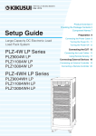
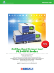
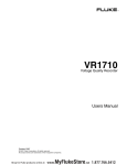
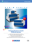
PART NO. Z1-005-160, IB022734 Feb. 2015 Operation Manual Electronic Load Booster PLZ2004WB PLZ2004WHB Checking the Package Contents When you receive the product, check that all accessories are included and that the product and accessories have not been damaged during transportation. If any of the accessories are damaged or missing, contact Kikusui distributor/agent. Accessories (PLZ2004WB) The power cord that is provided varies depending on the destination for the product at the factory-shipment. or Rated voltage: 125 Vac PLUG: NEMA5-15 [85-AA-0003] Power cord (1 pc.) The PLZ2004WB/PLZ2004WHB Load Booster is used to increase the input current to the PLZ1004W/PLZ1004WH Electronic Load. One PLZ1004W/PLZ1004WH is made the master unit, and load boosters connected in parallel operate as slave units. Number of load boosters 1 2 3 4 Maximum current/ Maximum power PLZ2004WB PLZ2004WHB 600 A / 3 000 W 150 A / 3 000 W 1 000 A / 5 000 W 1 400 A / 7 000 W 1 800 A / 9 000 W or Rated voltage: 250 Vac Rated voltage: 250 Vac PLUG: CEE7/7 PLUG: GB1002 [85-AA-0005] [85-10-0790] [Q1-500-096] If necessary, attach to the product. [A8-900-153] [Q1-900-020] Heavy object warning label (1 pc.) Load input terminal cover (2 pcs.) [with auxiliary band] 250 A / 5 000 W 350 A / 7 000 W 450 A / 9 000 W [M1-100-027] [M5-101-009] [M4-100-009] [Z1-005-160] Operation manual (1 copy) Set of screws for the load input terminal (2 sets) About the Operation Manuals This manual contains an overview of the PLZ2004WB/PLZ2004WHB electronic load booster and information about connecting, maintenance, and using it. For information on how to perform parallel operation, see the PLZ-4W/PLZ-4WH Series Electronic Load User's Manual. These operation manuals are intended for users of electronic loads and their instructors. Explanations are given under the presumption that the reader has knowledge of electronics and electronic loads. Every effort has been made to ensure the accuracy of this manual. However, if you have any questions or find any errors or omissions, please contact your Kikusui agent or distributor. If you find any misplaced or missing pages in the manuals, they will be replaced. If the manual gets lost or soiled, a new copy can be provided for a fee. In either case, please contact your Kikusui agent or distributor, and provide the "Kikusui Part No." given on the cover. After you have finished reading this manual, store it so that you can use it for reference at any time.。 Accessories (PLZ2004WHB) The power cord that is provided varies depending on the destination for the product at the factory-shipment. or or Rated voltage: 125 Vac Rated voltage: 250 Vac Rated voltage: 250 Vac PLUG: NEMA5-15 PLUG: CEE7/7 PLUG: GB1002 [85-AA-0004] [85-AA-0005] [85-10-0790] Power cord (1 pc.) If necessary, attach to the product. [Q1-500-085] [P2-000-228] Load input terminal cover (1 pc.) Lock plate (2 pcs.) [A8-900-153] Heavy object warning label (1 pc.) [M1-100-012] Features [M5-101-007] [M4-100-007] [Z1-005-160] Operation manual (1 copy) • Up to four load boosters can be connected in parallel. Set of screws for the load input terminal (2 sets) • The combination of PLZ2004WBs and a PLZ1004W master unit can create an electronic load of up to 9 kW and 1 800 A. The combination of PLZ2004WHBs and a PLZ1004WH master unit can create an electronic load of up to 9 kW and 450 A. The master unit displays the total current and total wattage. The units connected in parallel can be used as a single electronic load. • The connection of the control cables is easy. The control cable used to connect between the master unit and the load booster and between each load booster is one flat cable each. • There is no power switch. The AC input power is turned ON/OFF by the master unit. KIKUSUI ELECTRONICS CORP. 1-1-3, Higashiyamata, Tsuzuki-ku, Yokohama, 224-0023, Japan TEL: +81-45-593-0200 Fax: +81-45-593-7571 Website http://www.kikusui.co.jp/en The newest version of the operation manual can be downloaded from Download service of Kikusui website. PLZ2004WB/PLZ2004WHB1 Safety Precautions Safety Symbols For the safe use and safe maintenance of this product, the following symbols are used throughout this manual and on the product. Note the meaning of each of the symbols to ensure safe use of the product. (Not all symbols may be used.) or Indicates that a high voltage (over 1000 V) is used here. Touching the part causes a possibly fatal electric shock. If physical contact is required by your work, start work only after you make sure that no voltage is output here. DANGER WARNING CAUTION Indicates an imminently hazardous situation which, if ignored, will result in death or serious injury. The following safety precautions must be observed to avoid fire hazards, electric shock, accidents, and other failures. Keep them in mind and make sure to observe them. Using the product in a manner that is not specified in this manual may impair the protection functions provided by the product. • This product must be used only by qualified personnel Users who understand the contents of this operation manual. ation Oper Manual • If unqualified personnel is to use the product, be sure the product is handled under the supervision of qualified personnel (those who have electrical knowledge). This is to prevent the possibility of personal injury. Purpose Indicates a potentially hazardous situation which, if ignored, could result in death or serious injury. Indicates a potentially hazardous situation which, if ignored, may result in damage to the product and other property. Shows that the act indicated is prohibited. use the product for purposes other than the product s intended use. • This product is not designed or manufactured for general home or consumer use. Input power Line Voltage • Use the product within the rated input power voltage range. • For applying power, use the power cord provided. (see page 7 ). Indicates a general danger, warning, or caution. • This product is designed as an equipment of IEC Overvoltage Category II (energy-consuming equipment supplied from the fixed installation). When this symbol is marked on the product, see the relevant sections in this manual. Protective conductor terminal. • Never Cover • Some Grounding • This Operation • If parts inside the product may cause physical hazards. Do not remove the external cover. Chassis (frame) terminal. On (supply) Off (supply) G N L In position of a bi-stable push control Out position of a bi-stable push control ck? Che product is IEC Safety Class I equipment (equipment with a protective conductor terminal). To prevent electric shock, be sure to connect the protective conductor terminal of the product to electrical ground (safety ground). a malfunction or abnormality is detected on the product, stop using it immediately, and remove the power plug from the outlet or turn off the circuit breaker of switchboard. Make sure the product is not used until it is completely repaired. • Do not disassemble or modify the product. If you need to modify the product, contact your Kikusui distributor/agent. Maintenance• To prevent the possibility of electric shock, remove and the power plug from the outlet or turn off the Inspection circuit breaker of switchboard before carrying out maintenance or inspection. • Check periodically that there are no tears or breaks in the power cord. • If the panel needs cleaning, gently wipe it using a soft cloth with water-diluted neutral detergent. Do not use volatile chemicals such as benzene or thinner. • To maintain the performance and safe operation of the product, it is recommended that periodic maintenance, inspection, cleaning, and calibration be performed. Adjustments• Kikusui service engineers will perform internal service and Repairs on the product. If the product needs adjustment or repairs, contact your Kikusui distributor/agent. 2PLZ2004WB/PLZ2004WHB Precautions to Be Taken When Moving the Product Precautions Concerning Installation Location Be sure to observe the following precautions when installing the product. • Do not use the product in a flammable atmosphere. To prevent the possibility of explosion or fire, do not use the product near alcohol, thinner, or other combustible materials, or in an atmosphere containing such vapors. • Avoid locations where the product is exposed to high temperature or direct sunlight. Do not install the product near a heater or in areas subject to drastic temperature changes. For this product's operating and storage temperatures, see this specifications. • Avoid high humidity. Do not install the product in high-humidity locations--near a boiler, humidifier, or water supply. For this product's operating and storage humidity, see this specifications. Condensation may occur even within the operating humidity range. In such cases, do not use the product until the condensation dries up completely. • Be sure to use it indoors. Note the following points when moving or transporting the product to the installation location. • Turn off the power switch. Moving the product while the power is turned on can cause electric shock or damage to it. • Have two or more people move the unit. The unit weighs over 20 kg. Have two or more people move the unit. Use extra precaution at inclines and steps. • Remove all wiring. Moving the product with the wires connected can cause wires to break or injuries due to the product falling over. • When transporting the product, be sure to use the original packing materials. Otherwise, damage may result from vibrations or from the product falling during transportation. • Be sure to include this manual. This product is designed for safe indoor use. • Do not install the product in a corrosive atmosphere. Do not install the product in a corrosive atmosphere or in environments containing sulfuric acid mist, etc. This may cause corrosion of various conductors and bad contacts of terminals inside the power supply leading to malfunction and failure, or in the worst case, a fire. • Do not install the product in a dusty location. Notation Used in the Guide • In this manual, the PLZ-4W Series Electronic Load is sometimes referred to as the PLZ-4W Series or "booster." In this manual, the PLZ-4WH Series Electronic Load is sometimes referred to as the PLZ-4WH Series or "booster." • In this manual, the PLZ2004W Electronic Load is sometimes referred to as the PLZ2004W. In this manual, the PLZ2004WH Electronic Load is sometimes referred to as the PLZ2004WH. Accumulation of dust can lead to electric shock or fire. • Do not use the product where ventilation is poor. Secure adequate space around the product so that air can circulate around it. Allow at least 20 cm of space between the inlet and vent holes and any walls or obstructions. • Do not place objects on the product. Placing objects on top of the product can cause failures (especially heavy objects). • The following markings are used in the explanations in the text. WARNING •Indicates a potentially hazardous situation which, if ignored, could result in death or serious injury. • Do not install the product on an inclined surface or location subject to vibrations. CAUTION The product may fall and break or cause personal injury. • Do not use the product in a location where strong magnetic or electric fields are nearby or a location where large amount of distortion and noise is present on the input power supply waveform. The product may malfunction. •Indicates a potentially hazardous situation which, if ignored, may result in damage to the product and other property. > Indicates menu settings that you select. The menu item to the left of the > symbol is a higher level menu. • Do not stack more than two units on top of each other. The units (load booster and master unit) can be stacked, but do not stack more than two units on top of each other for safety reasons. If you are using multiple load boosters, it is recommended that they be mounted on a rack. Do not stack more than two units. I MON OUT I MON OUT TR I G OUT POWER REMOTE ELECTRONIC LOAD PLZ2004WHB POWER ELECTRONIC LOAD ELECTRONIC LOAD PL Z2004WHB TR I G OUT POWER PLZ2004WHB POWER PLZ2004WB/PLZ2004WHB3 Front Panel and Rear Panel ÐÌÚ²°°´× 1. POWER lamp ² Æòïîô ðáîåì Illuminates when the power switch of the master unit is on when the load booster is connected in parallel with the master unit. It indicates that AC input power is being supplied. 2. Air intake (louver) ELECTRONIC LOAD PL Z2004WB 2000W x-xxxV 0 - xxxA POWER 3. J1 and J2 connectors (only on the PLZ2004WB) ± Òåáò ðáîåì ³ ¶ Connectors used to connect the optional flat cable to enable parallel operation. The upper connector is the J1 connector, and the lower connector is the J2 connector. DC INPUT J1 2000W 1.5 -150V 0 - 400A J2 Inlet port used to exhaust the internal heat using a fan. WARNING TO AVOID ELECTRIC SHOCK, THE POWER CORD PROTECTIVE GROUNDING CONDUCTOR MUST BE CONNECTED TO GROUND. DO NOT REMOVE COVERS, REFER SERVICING TO QUALIFIED PERSONNEL. ឬ֖ ̜᩻ඨɁȲɔǾоӌໃɽ˂ʓɁÇÎÄ፷ɥ ᆬȾ٥ȪȹȧΈႊȢȳȨȗǿ టᛏֿɁɵʚ˂ɂፏߦȾɝ۶ȪȹɂȗȤɑȮɦǿ AC INPUT 100-240V 47-63Hz 200VA MAX · 4. PARALLEL connector (only on the PLZ2004WHB) ¸ Connectors used to connect the optional flat cable to enable parallel operation. The upper connector is the IN connector, and the lower connector is the OUT connector. ¹ 5. Remote sensing terminal (only on the PLZ2004WHB) ÐÌÚ²°°´×È ² Æòïîô ðáîåì The remote sensing terminal is not used. 6. DC INPUT (Load input terminal) Input connector used to connect to the equipment under test. 7. AC INPUT connector ELECTRONIC LOAD PL Z2004WHB AC power input connector. 2000W 5-650V 0-100A POWER ± Òåáò ðáîåì ´ µ DC INPUT ¶ 8. Serial number 9. Air outlet 2000W 5-650V 0-100A PARALLEL Air outlet used to exhaust the internal heat using a fan. IN OUT AC INPUT 100-240V 50-60Hz 200VA MAX · WARNING ⼊๔ DO NOT REMOVE COVERS. N O OPER ATOR SER V I CE A B L E PAR TS INSIDE. REFER SERVICING TO QUA L IFIED SERVICE PERSONNEL. UNPLUG THE MAINS SUPPLY CORD BEFORE HANDLING THE CORD OR LOAD WIRES. ᧄຠ䈱䉦䊋䊷䈲䇮⛘ኻ䈮ข䉍ᄖ䈚䈩䈲䈇䈔䉁䈞䉖䇯 ౝㇱ䈱ὐᬌ䈲ᒰ␠䈏䉄䈢䉰䊷䊎䉴䊙䊮䈮ᆔ⸤䈚䈩䈒䈣䈘䈇䇯 ਥ㔚Ḯ䉮䊷䊄䈶⽶⩄✢䈱ข䉍ᛒ䈇䈲䇮ᔅ䈝ਥ㔚Ḯ䊒䊤䉫䉕ᛮ䈇䈩䈎䉌ⴕ䈦䈩䈒䈣䈘䈇䇯 WEIGHT APPROX 24kg ¹ ¸ 4PLZ2004WB/PLZ2004WHB Parallel Connection Use a signal wire to connect the load booster to the master unit. Use a load wire to connect the load booster to the EUT. You can connect up to four boosters. you are using PLZ2004WBs, connect the J2 4 Ifconnector of the first booster to the J1 connector of the second booster. If you are using PLZ2004WHBs, connect the PARALLEL OUT connector of the first booster to the PARALLEL IN connector of the second booster. Continue connecting all the remaining boosters in the same manner. Separate the load cable from the flat cable as much as possible to prevent unstable operation. + – Master unit DC INPUT J1 1000W 1.5 -150V 0 - 200A J2 This completes the procedure for connecting the signal wires. Flat cable PC02-PLZ-4W (Option) Load wire + – Load booster 1 DC INPUT J1 2000W 1.5 -150V 0 - 400A J2 + – Equipment under test Flat cable PC01-PLZ-4W (Option) Load wiring The cautions and things that you need to consider when you are wiring the loads are the same as when you are wiring the loads of the PLZ1004W/PLZ1004WH. To ensure operational stability, see "Methods for Ensuring Stable Operation" in chapter 1, "Installation and Preparation" of the PLZ1004W/PLZ1004WH User's Manual. WARNING + Load booster 2 – •Improper use of load wires may lead to fire. Use load wires whose capacity is adequate for the PLZ-4W/PLZ-4WH's rated output current. DC INPUT J1 2000W 1.5 -150V 0 400A J2 - Example: Parallel connection of two load boosters •Possible electric shock. Use load wires whose rated voltage meets or exceeds the PLZ-4W/PLZ-4WH's isolation voltage. For details of isolation voltage, see "General specifications" of this manual. Connecting the Signal Cables [84-49-0071] A protective socket is attached to the J1 connector ( P L Z 2 0 0 4 W B ) o r PA R A L L E L c o n n e c t o r (PLZ2004WHB) when the PLZ2004WB/PLZ2004WHB is in the factory default state. Keep the protective socket in a safe place so that you can attach it to the connector when the connector is not in use. If the protective socket is damaged or lost, contact your Kikusui agent or distributor. Use the optional flat cable for the signal wire. It comes in two lengths. Model Length Explanation PC01-PLZ-4W 300 mm (11.81") For connecting boosters to each other PC02-PLZ-4W 550 mm (21.65") For connecting the master unit to a booster CAUTION Use a load wire with sufficient diameter for the current as well as non-flammable or flame-resistant cover. If the wiring that you use for the load has a high resistance, the voltage will drop significantly when current flows, and the voltage at the load input terminals may fall below the minimum operating voltage. Using the following table as a reference, select wiring whose nominal cross-sectional area is as thick as possible. A wire's temperature is determined by the resistive loss based on the current, the ambient temperature, and the wire's external thermal resistance. The following table shows the current capacity of heatresistant vinyl wires that have a maximum allowable temperature of 60 ºC when one of the wires is separated and stretched out horizontally in air in an ambient temperature of 30 ºC. The current must be reduced under certain conditions, such as when vinyl wires that have a low heat resistance are used, when the ambient temperature is 30 ºC or greater, or when wires are bundled together and little heat is radiated. CAUTION Nominal Cross- AWG (Reference Cross- Allowable Current1 Sectional Area Sectional Area) [A] (Ta = 30 ºC) To avoid damaging the product, observe the following precautions. [mm2] •Do not connect the cables to the wrong connectors. •Do not operate the PLZ-4W or PLZ4WH alone with the flat cable 2 3.5 5.5 8 14 22 30 38 50 60 80 100 125 150 200 250 325 connected. •Do not mix the PLZ2004WB and PLZ2004WHB units together in parallel operation. that the master unit's POWER switch is turned 1 Check off ( ○ ). heck that the booster power cords are not 2 Cconnected. you are using PLZ2004WBs, connect the J2 3 Ifconnector of the master unit to the J1 connector of the first booster. If you are using PLZ2004WHBs, connect the PARALLEL OUT connector of the master unit to the PARALLEL IN connector of the first booster. 1. [mm2] 14 12 10 8 6 4 2 1 1/0 2/0 3/0 4/0 - (2.08) (3.31) (5.26) (8.37) (13.3) (21.15) (33.62) (42.41) (53.49) (67.43) (85.01) (107.2) - 27 37 49 61 88 115 139 162 190 217 257 298 344 395 469 556 650 KikusuiRecommended Current [A] 10 20 30 50 80 100 200 300 - Excerpts from Japanese laws related to electrical equipment. PLZ2004WB/PLZ2004WHB5 Connecting the Load Wires Consider the current that you will be using, and use wires that are thick as possible. Also, wire them as short as possible. Use load wires that have the same length and cross-sectional area. each of the booster's load input terminals, wrap 6 For the included auxiliary band around the space between the rear panel and the bolt. The auxiliary band prevents the load input terminal cover from slipping. Wrap the belt tightly to fill in the space between the panel and the bolt. The load input terminal of the master unit (PLZ1004W/PLZ1004WH) is not designed to handle as large a current as the load input terminal of the booster. Separate the load wires that are connected to the EUT into those that are connected to the master unit and those that are connected to the boosters. Load input terminals Use wires that are as thick as possible, and wire them as short as possible. Use load wires that have the same length and cross-sectional area. Wrap the auxiliary band around the space between the rear panel and the bolt. Wrap the belt tightly to fill in the space between the panel and the bolt. Auxiliary band the load input terminal covers around the 7 Wrap booster's load input terminals. Master unit Equipment under test Load input terminals Load input terminal cover Booster 1 Load input terminals Booster 2 Example: Connection of two boosters WARNING Wrap the load input cover over the auxiliary band and the load input terminal. Wrap the load input terminal cover so that there is as little space here as possible. the load wires of the master unit and the 8 Connect boosters to the EUT. 9 Check the polarity of the connections. Possible electric shock. •Do not touch the load input terminal while the power is on. •Be sure to use the load input terminal cover. This completes the procedure for connecting the load wires. CAUTION ■ •To avoid damaging the product, observe the following precautions. Be sure to use the load input terminals on the rear panel on the master unit. Do not connect other equipment to the load input terminal on the front panel. The methods for connecting load wires to a booster's load input terminal and for using the load input terminal covers and lock plates are the same as the methods for the PLZ1004WH. For details, see the PLZ1004WH user's manual. •There is a danger of overcharge. Attach crimping terminal to the wire and use the set of screws that came with the package for connection. ■ that the POWER switch of master unit is off ( 1 Check ). Connecting load wires to the PLZ2004WB 1 heck that the booster power cords are not 2 Cconnected. 3 Make sure that the output of the EUT is off. load wires to the load input terminal on the 4 Connect master unit's rear panel as shown in the PLZ1004W Check that the POWER switch of master unit is off ( user's manual. ). the load wires to the load input terminals on 5 Connect the booster using the included load input terminal screw set. Bolt (M12 × 25) Spring washer (M12) Be sure to use the included screw set. Connecting load wires to the PLZ2004WHB heck that the booster power cords are not 2 Cconnected. 3 Make sure that the output of the EUT is off. load wires to the load input terminal on the 4 Connect master unit's rear panel as shown in the PLZ1004WH user's manual. load wires to the load input terminal on the 5 Connect booster as shown in the PLZ1004WH user's manual. the load wires of the master unit and the 6 Connect boosters to the EUT. 7 Check the polarity of the connections. This completes the procedure for connecting the load wires. Crimping terminal Nut (M12) 6PLZ2004WB/PLZ2004WHB Connecting the Power Cord This product falls under IEC Overvoltage Category II (energyconsuming equipment supplied from the fixed installation). WARNING Possible electric shock. •This product is IEC Safety Class I equipment (equipment with a protective conductor terminal). Be sure to earth ground the product to prevent electric shock. •Connect the protective conductor terminal to earth ground. Use the supplied power cord to connect to an AC power line. If the supplied power cord cannot be used because the rated voltage or the plug shape is incompatible, have a qualified engineer replace it with an appropriate power cord that is 3 m or less in length. If obtaining an appropriate power cord is difficult, consult your Kikusui agent or distributor. A power cord with a plug can be used to disconnect the product from the AC line in an emergency. Connect the plug to an easily accessible power outlet so that the plug can be removed from the outlet at any time. Be sure to provide adequate clearance around the power outlet. Do not use the supplied power cord for other devices. The load booster does not have a power switch. The AC input power is turned on/off in sync with the master unit. that the AC power supply is within the input 1 Check power supply range of the product. The voltage that can be applied is any of the nominal power supply voltages in the range of 100 Vac to 240 Vac. The frequency is 50 Hz or 60 Hz. the power cord to the AC INPUT connector 2 Connect on the rear panel. the power cord plug to an outlet with a 3 Connect ground terminal. Setting the Master Unit After you finish making the connections, set the number of boosters on the master unit. If the master unit's response speed has been set to 1/1, its response speed is changed to 1/2 to ensure operational stability. You can use the menu settings to return the response speed to 1/1. 1 Turn on ( ) the power to the master unit. On the master unit, from the menu, select "2. Configuration" > "1.Master/Slave" > "Operation" > "MASTER." "Booster" to the number of booster units that 2 Set have been connected. 3 Turn off ( ) the power to the master unit. The menu settings are applied. This completes the settings that are necessary to use boosters. Performing Parallel Operation After you finish configuring the settings on the master unit, you can perform parallel operation. During parallel operation, the slew rate and response speed settings on the master unit are used. If large voltage drops occur because of increased wiring inductance or if oscillations occur due to instability of the product caused by current phase lag, reduce the response speed to ensure stable operation. Turning the Power On and Off ■ Turning the power on Turn the master unit's POWER switch on. This will also turn the boosters on. Set the operation mode and configure the settings on the master unit, and turn the load on. ■ Turning the power off Turn the master unit's POWER switch off. This will also turn the boosters off. Ending Parallel Operation To end parallel operation and return to independent operation, turn the master unit off, and then remove the flat cables. To return the master unit to independent operation, from the menu, select "2. Configuration" > "1.Master/Slave" > "Booster" > "-," and then restart the unit. CAUTION To avoid damaging the product, observe the following precautions. Do not operate the PLZ-4W or PLZ-4WH alone with the flat cable connected. PLZ2004WB/PLZ2004WHB7 Cleaning the Dust Filter A dust filter is installed on the inside of the louver on the front panel. Periodically clean the filter to prevent clogging. ■ Cleaning the PLZ2004WHB's dust filter 1 Remove the lower louver from the panel. While lifting the bottom of the removal mark with your finger tips, slide the entire louver to the right. Then, pull it toward you. CAUTION •Clogged dust filters hinder the cooling of the inside of the instrument and can cause a malfunction and shortening of the service life. •When the Booster is in operation, air is sucked through the dust filter to cool the load booster. If moister is included in the dust filter, the temperature or humidity inside the Booster increases and may cause a malfunction. ■ Cleaning the PLZ2004WB's dust filter the louver from the panel by placing a finger 1 Remove on the 2nd level of the louver and pulling down the 1st level while pulling it toward you. If the louver does not come off easily, pressing down the top level of the louver will ease the work. 2nd level 1st level Louver ② ② ELECTRONIC LOAD PL Z2004WHB 2000W 5-650V 0-100A POWER Removal mark ① While lifting the bottom of the removal mark with your finger tips (①), slide the entire louver to the right (②). all the remaining louvers in the same manner 2 Remove as was shown in step 1. the dust filter from the inside of the louver 3 Remove and clean it. There is a hook on the louver tab. Be sure not to get the dust filter caught in the hook when removing the dust filter from the louver. Remove the dust on the dust filter such as by using a vacuum cleaner. If the filter is extremely dirty, clean it using a waterdiluted neutral detergent and dry it completely. Dust filter Hook the dust filter from the inside of the louver 2 Remove and clean it. Remove the dust on the dust filter such as by using a vacuum cleaner. If the filter is extremely dirty, clean it using a waterdiluted neutral detergent and dry it completely. Dust filter Tab Tab Louver Hook Guide the dust filter along the guide and attach it to 4 Align the louver. Be sure to attach it firmly until the tab hooks of the louver completely passes through the dust filter. 5 Attach the upper louver first. Louver 3 Attach the dust filter to the louver. Firmly attach the dust filter so that the louver's tabs protrude out of the top of the dust filter. the louver to the panel by pulling up on the 4 Attach louver while holding the 2nd level of the louver with your hand until the pin is fixed in place. Align the tab on the inner side of the louver to the panel groove and slide the louver to the left to attach it. You can easily attach the louver by aligning the long tabs (five locations) with the grooves. Tab (long) Tab (short) Upper louver Slide the louver to the left to lock the louver in place. Groove for attaching the louver Pin Pass the long tabs on the back side of the louver through the grooves on the panel indicated by circles. all the remaining louvers in the same manner 6 Attach as was shown in step 5. 8PLZ2004WB/PLZ2004WHB Specifications Calibration The booster is shipped from the factory after carrying out a strict calibration. However, to maintain the performance, periodic calibration is recommended. Calibrate the master unit and the boosters as a single electronic load in the same manner as when you calibrate the master unit alone. For details, see "Calibration" in the PLZ1004W/PLZ1004WH User's Manual. For calibration, use shunt resistors and a regulated DC power supply that match the product's current capacity. Rack mount bracket Electrical Specifications Unless specified otherwise, the specifications are for the following settings and conditions. • Warm-up period: 30 minutes (with current flowing) • Ambient temperature: 23 ºC 5 ºC • TYP: These are typical values that are representative of situations where the PLZ2004WB/PLZ2004WHB operates in an environment with an ambient temperature of 23 ºC. These values do not guarantee the performance of the PLZ2004WB/PLZ2004WHB. • % of set denotes % of the input voltage or input current setting. • % of f.s denotes % of the rated input voltage, rated input current or rated input power. The following brackets are available as options. PLZ2004WB PLZ2004WHB Inch-rack EIA standard KRB3-TOS KRB4 Milli rack JIS standard KRB150-TOS KRB200 For details, contact Kikusui distributor/agent. PLZ2004WB • % of rdng denotes % of the input voltage or input current reading. ■ PLZ2004WB Operating voltage 1.5 Vdc to 150 Vdc1 Current 400 A Power 2 000 W Current setting accuracy2 (1.2 % of set + 1.1 % of f.s)3 1. 132 (5.20) 2. 3. 37.5 (1.48) 57 (2.24) KRB3-TOS 465 ( 1 479 ( 8.31) 18.86 ) Rating (PLZ2004WB) ■ Minimum voltage at which the current starts flowing to the PLZ2004WB is approx. 0.3 V. The PLZ2004WB detects no signal at an input voltage less than or equal to approx. 0.3 V and an input current less than or equal to approx. 1 % of the range rating. If the input voltage is gradually increased from 0 V, no current will flow until 0.3 V is exceeded. Once a current greater than or equal to 1 % of the range rating starts flowing, the current can flow at voltages less than equal to 0.3 V. Condition in which the booster is connected to the master unit. M range applies to the full scale of H range. Rating (PLZ2004WHB) PLZ2004WB 149 (5.87) 1. 24.5 (0.965) 460 ( 1 479 ( 8.11) 18.86 ) 100 (3.94) KRB150-TOS Operating voltage Current Power Input resistance when the load is off 2. PLZ2004WHB PLZ2004WHB Operating range Setting range Resolution1 Ripple1 102 37.5 (4.02) (1.475) 177 (6.97) 1. 2. 1. 2. 199 (7.83) 50 50 50 (1.97)(1.97)(1.97) When one PLZ2004WHB is connected. Condition in which the booster is connected to the master unit. PLZ2004WHB CC mode1 CR mode CV mode CP mode KRB200 24.5 (0.96) H range M range L range 0 A to 100 A 0 A to 10 A 0 A to 1 A 0 A to 105 A 0 A to 10.5 A 0 A to 1.05 A 10 mA 1 mA 0.1 mA PLZ1004WH specification x (total power capacity/1 kW) (TYP) • Accuracy of setting PLZ2004WHB 457.5 478.9 (18.01) (18.8 5) Minimum voltage at which the current starts flowing to the PLZ2004WHB is approx. 0.5 V. The PLZ2004WHB detects no signal at an input voltage less than or equal to approx. 0.5 V and an input current less than or equal to approx. 1 % of the range rating. If the input voltage is gradually increased from 0 V, no current will flow until 0.5 V is exceeded. Once a current greater than or equal to 1 % of the range rating starts flowing, the current can flow at voltages less than equal to 0.5 V. Condition in which the booster is connected to the master unit. • Constant current (CC) mode KRB4 457.5 (1 478.9 8.01) (18.8 5) PLZ2004WHB 5 Vdc to 650 Vdc1 100 A 2 000 W 2.21 MΩ2 (1.2 % of set + 1.1 % of f.s2) (1.2 % of set + 1.1 % of f.s2)(TYP) (0.2 % of set + 0.2 % of f.s)(TYP) (5 % of f.s2)(TYP), at 23℃ 5℃ Condition in which the booster is connected to the master unit. The full scale of the range. However, for the M range, it is the full scale of the H range. • Measurements Unit: mm (inch) PLZ2004WHB Accuracy of voltmeter Accuracy of ammeter Wattmeter 1. (0.1 % of rdng + 0.1 % of f.s)(TYP) (1.2 % of rdng + 1.1 % of f.s1)(TYP) Displays the product of the voltmeter reading and ammeter reading. The full scale of the range. However, for the M range, it is the full scale of the H range. PLZ2004WB/PLZ2004WHB9 ■ Dimensions Protection function Protection functions other than those listed below operate on the PLZ1004W/ PLZ1004WH. For details, see the PLZ-4W/PLZ-4WH user's manual. PLZ2004WB/PLZ2004WHB Overheat protection (OHP) Turns off the load when the heat sink temperature reaches 95 ºC Reverse connection Protection by fuse protection (REV) General Specifications PLZ2004WB PLZ2004WHB 0 ºC to 40 ºC (32 ºF to 104 ºF) 20 %rh to 85 %rh (no condensation) -25 ºC to 70 ºC (-13 ºF to 158 ºF) Input frequency range Less than or equal to 90 %rh (no condensation) 100 Vac to 240 Vac (90 Vac to 250 Vac) single phase, continuous 47 Hz to 63 Hz Power consumption Inrush current Protective conductor current 200 VAmax 35 A --- Insulation resistance Withstand voltage Primary - input connector, Primary - chassis, Input connector chassis Primary - input connector, Primary - chassis, Dimensions Weight Accessories Power cord Load input terminal cover Screw set for th load input Heavy object warning label Operation manual Electromagnetic compatibility (EMC)3 Safety 4 1. 2. 3. 4. 120 A1 600 µA (100 Vac at 50 Hz; TYP) 500 Vdc, 1 000 Vdc, 30 MΩ or more 30 MΩ or more (ambient humidity of (ambient humidity of 70 %rh or less) 70 %rh or less) See outline drawing. Approx. 24 kg (52.91 lb) 1 pc. (Cable length of 2.4 m) 2 sets (cover and 1 pc. (cover and two auxiliary band) lock plates) 2 sets (bolts, nuts, and spring washers) MAX600 (23.62) 550 (21.65) PLZ2004WB Unit: mm (inch) MAX590 (23.23) 550 (21.65) 430 (16.93) No abnormalities at 1 500 Vac for 1 minute PLZ2004WHB Unit: mm (inch) 1 pc. 1 pc. Conforms to the requirements of the following directive and standard. EMC Directive 2004/108/EC EN 61326-1 EN 61000-3-2 EN 61000-3-3 Conforms to the requirements of the following directive and standard. Low Voltage Directive 2006/95/EC3 EN 61010-1 Class I Pollution degree 2 Approximately 70 A when 100 Vac is applied If the input voltage or input frequency is different, the following equation can be used to calculate the value. Protective conductor current = MAX440 (17.32) 429.5 (16.91) 128 (5.04) MAX150 (5.91) Environment Operating temperature range Operating humidity range Storage temperature range Storage humidity range Input line voltage range 173 (6.81) MAX190 (7.48) ■ Input voltage [V] 100 [V] × Input frequency [Hz] 50 [Hz] Trademarks Microsoft and Windows are either registered trademarks or trademarks of Microsoft Corporation in the United States and/or other countries. × 500 [µA] Only on models that have CE marking on the panel. Not applicable to custom order models. This instrument is a Class I equipment. Be sure to ground the protective conductor terminal of the instrument. The safety of the instrument is not guaranteed unless the instrument is grounded properly Inquiry about Product When making an inquiry about the product, please provide us with the following information. Model (indicated at the top section on the front panel) Serial number (indicated at the bottom section on the rear panel) Copyrights Reproducing or reprinting this operation manual or any part of it without the permission of the copyright holder is strictly prohibited. Product specifications and manual contents are subject to change without notice. © 2010 Kikusui Electronics Corp. 10PLZ2004WB/PLZ2004WHB