1
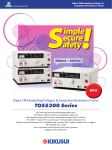
Hipot (Withstanding Voltage) &
Insulation Resistance Tester
S !
imple
ecure
afety
200mA or more!*
Max rated output: 500VA
Short-circuit current:
* When the output voltage is 1.0kV or greater
Hipot (Withstanding Voltage) & Insulation Resistance Tester
TOS5300 Series
The PWM amp system provides highly-stable output
5kV/100mA (500VA) AC Hipot (withstanding voltage) test
6kV/maximum output 50W DC Hipot (withstanding voltage) tester (TOS5301)
25V-1000V (7 steps), 500V or greater, up to 5.00GΩ Insulation Resistance test
High-precision measurement ±1.5% of reading (with voltmeter 500V or higher, Ammeter 1mA or higher)
Rise time/Fall time control
Key lock function and Protection cover for key operation
Equipped with USB interface
Highly stable
Newly developed, high-efficiency
PWM switching amplifier !
Providing a stable output of high
voltage without being affected by
AC line variation. Ensure the user
to perform highly reliable testing
with confidence, even in regions
with large voltage variations. (Input
voltage fluctuation rate: ±0.3%)
Reducing
the tact time
Increasing the productivity!
Capable of setting
the test time from 0.1s
S !
Supporting the
World-wide
input voltage
Usable globally !
Usable in any country without changing the
input power supply.
imple
ecure
afety
A new standard for
Hipot (Withstanding voltage) &
Insulation resistance testing
Applied to World-Wide
input voltage
Selectable output frequency !
200mA or more!*
500VA
Weighs Approx. 15 kg
40% lighter than conventional models
*Compared to TOS5300 and TOS8870A
* When the output voltage is 1.0kV or greater
H i p o t ( W i t h s t a n d - V o l t a g e ) & I n s u l a t i o n R e s i s t a n c e Te s t e r
TOS5300Series
3 model
Features
and
Functions
2
Prevents from an excessive stress applied to the
EUT or for standard tests.
▲ Rise time control waveform
(example)
▲ Fall time control waveform
(example)
Pursuing usability
and safety
All new design of the control
panel and output terminals!
Eliminates the projected components of output
terminals, and equips with a new type of the LOW
terminal. Pursuing the improvement of safety
and a convenience in production line, such as
providing the protection cover for the front panel.
Lightweight &
Compact design
Increasing your work efficiency!
Max rated output:
Equipped with a Rise time/
Fall time control function
▲ Output voltage wave form
The instrument not rely on the input power
environment. Supplying the stable test voltage
with 50/60 Hz frequencies.
Short-circuit current:
Rise/Fall Time
control function of
the applied voltage
▲ Output terminal
Left : HIGH (red)
Right : LOW
(black, with lock function)
▲ View with the protection cover
removed from front panel
The "TOS5300 Series" is a series of test instruments used in Hipot (withstanding
voltage) tests and insulation resistance tests, two of the four tests regarded
as necessary for ensuring the safety of electrical products. With an output
of 5 kV/100 mA (AC) and 6 kV/10 mA (DC), the series can be used in Hipot
(withstanding voltage) & insulation resistance testing of electronic equipment
and electronic parts, based on the requirements of IEC, EN, UL, VDE, JIS, and
other international safety standards and the Electrical Appliance and Material
Safety Law. Also, the test voltage stability is improved with the adoption of a
newly developed switching amplifier. Since the output voltage can be kept
constant even when the AC line voltage or frequency changes, consistent
testing can be performed, even when the power supply environment is in an
unstable region. The TOS5300 is also equipped with a number of features that
are capable of meeting a variety of test needs. It is a new low-cost standard
model that provides thorough operability, reliability and safety.
Applied test / Model
AC Hipot (Withstanding voltage) test (ACW)
DC Hipot (Withstanding voltage) test (DCW)
Insulation Resistance test (IR)
TOS5300
TOS5301
TOS5302
4
4
4
4
4
● ACW: 5 kV/100 mA; DCW: 6 kV/50W ● IR: 25-1000V (7 steps)/500V or greater, up to 5.00 GΩ ● High-precision measurement ± 1.5% of reading (Voltage: 500V or
greater ; Current: 1 mA or more) ● Rise time / Fall time control function ● Discharge function ● World-wide input voltage ● AUTO function ● USB interface ●
Panel memory function (3 sets) ● Key lock and Protection cover for panel operation
Basic performance ensure the reliable testing
The achievement of AC Hipot (Withstanding voltage) testing with a constant stable output!
[ Input voltage variation : ± 0.3%]
The output waveform is
essential factor in Hipot
(Withstanding voltage) testing!
A conventional Hipot (Withstanding voltage) tester
boosts and outputs the AC line's input voltage
through the use of a slide transformer. With this
slide transformer system, input voltage fluctuations
will affect the output, preventing tests from being
performed properly. At times, the application of
distortion voltage applied to the EUT may cause a
failure of new product (accelerating a deterioration
of components). Since the TOS5300 Series equips
with a high-efficient PWM amplifier that can output
a stable high-voltage without being affected by the
variation of AC power line, users can perform "safe",
"stable", and highly "reliable" tests with confidence,
even in regions with large voltage variations.
▲ AC output waveform of the TOS5300 Series
▲ AC output waveform of the slide
transformer system
Realizing high-precision measurement with
high-resolution and high-speed judgement
Supporting the World-wide
input voltage
Equipped with a high-accuracy, high-resolution of True RMS
measurement circuit, including a Voltmeter with ±1.5% of reading
(500V or greater) / minimum resolution of 1V, and an Ammeter with
±1.5% of reading (1 mA or more) / minimum resolution of 1µA. In
addition, it is also equipped with an Auto range function. The Lower
limit judgment accuracy achieves a level of performance equivalent
to the Upper limit judgment accuracy that enables to detect for such
a poor contact or disconnections of test leads. Moreover, it realizes
the fast judgment by the test time of 0.1 second, while reliable testing
can be performed, thanks to high-precision, high-resolution, highspeed measurement and the judgment functions.
Usable globally !
This is
different,
too!
Usable in any country, without changing
the input power supply.
Selectable output frequency !
The instrument not rely on the input power environment.
Supplying the stable test voltage with 50/60 Hz frequencies.
Reducing the tact time
Reduction of the tact time leads to improve the productivity.
However, it has been an issue that reducing the tact time may cause
to worsen the measurement accuracy when the test time is faster
than the measuring response speed. The TOS5300 series has been
achieved to set the test time from 0.1s.
(Model TOS5301)
6kV/50WDC Hipot (Withstanding voltage) test
Capable to perform DC Hipot (Withstanding voltage) test up to 6 kV.
(Model TOS5301) Equipped with a stable DC/DC converter with a
low-ripple and the load variation of 3% or less.
Insulation resistance test for 25V to 1000V*
Capable of precision
measurement from 0.00mA
▲ AC Hipot (Withstanding voltage) test settings display (example)
The TOS5302 is equipped with an insulation resistance tester. The test
voltages can be set from 25V, 50V, 100V, 125V, 250V, 500V and 1000V.
And for setting at 500V and above, it can perform the insulation
resistance test up to 5.00 GΩ.
*At 500V and above, measurements up to 5.00 GΩ are possible.
3
Functions and Safety that focus in the production site
Protection cover prevents physical operation error in the production site
Prevents a physical operation
error by installing the protection
cover on the control keys.
In many cases, workers on electronic
equipment production lines and inspection
lines are not technical experts. Therefore, it
is possible that the operators may change
setting conditions and make operation
errors. In order to prevent from such cases,
the TOS5300 is equipped with a key lock
function and a protection cover to disable a
physical key operation from the front panel.
▲ View with the protection cover removed
Storing the protection cover for the key operation to the base of unit. ▶
During the periods of operation with the protection cover removed, such as
when the test conditions are frequently changed and tests are performed
repeatedly, the protection cover can be stored at the base.
New design of output terminal improves safety and functionality
Eliminates the projected components from the
front panel. The new design of LOW terminal.
In consideration of safety for the operator and the environment, the
output terminal of HIGH-side has been placed in the most distant
location from the control area. The free rotation machanisim protects
from twisting (or breaking) of the cable. Also, with having the lock
function for the LOW terminal on the main unit, the metal plate is no
longer attached to the test lead of LOW-side, and it makes to resist
damage to the test lead. Because of elimination of these projected
components, the TOS5300 can avoid from unexpected accidents
such as when the unit travels to other location. And also when the
test lead is snagged on something, or unexpected stress is applied
on the test lead, the High (High-voltage) test lead is designed to
disconnect easily, but the Low (ground) test lead is designed to resist
disconnection.
In order to prevent the insertion error, the color coding of the cable
are classified to HIGH (red) and LOW (black) , and the plug shape of
terminal are also different design.
▲ Flat surface design of the HIGH terminal with free rotation mechanism,
and the LOW terminal with lock function
P O
I
N T
It could be a cause of defect if the cable are incorrectly wired for the
HIGH (High-voltage) side and LOW (Low-voltage) side. In order to
prevent the insertion error, the protection plate is attached to the
Low-voltage (Black) test lead.
Monitoring the output voltage and protection when applying an overvoltage
by the operation error
LIMIT VOLTAGE function
Monitoring output voltage function
Prevents the user from setting a test voltage that exceeds the preset voltage.
If the output voltage exceeds the setting voltage of (± 350V), it turns
off the output and the system switches to PROTECTION mode.
In order to handle kilo's of high voltage when the Hipot (Withstand
voltage) and insulation tests are conducted, there are number of safety
measures are required to take place. Having with these functions
improve, the operational safety and the protection for the EUT.
▲ LIMIT VOLTAGE setting (example)
4
Functions and Safety that focus in the production site
Rise time / Fall time control function
Rise time control function
The Rise time control function enables you
to increases the test voltage gradually to
reach the setting voltage while the AC Hipot
(Withstanding voltage) test is conducted.
The voltage rise time can be set from 0.1s to
10.0s at a resolution of 0.1s.
Fall time control function
The Fall time control function enables you
to decrease the test voltage gradually when
the PASS judgment is made at the AC Hipot
(Withstanding voltage) test. The voltage fall
time is fixed at 0.1 s. (OFF is also selectable).
▲ Rise time control waveform (example)
P O
I
▲ Fall time control waveform (example)
N T
The rise time control function is to prevent the EUT (test object) from being exposed
to stress that exceeds the required amount. The Hipot (Withstanding voltage) test is
conducted to verify the safety performance of the EUT and which test voltage for Hipot
(Withstanding voltage) test is applied approximately five to ten times greater than the
voltage that handles by the EUT. If a high voltage is applied rapidly with no rise time, the
transitional large voltage (current) will be occurred, and it may cause a damage to the EUT.
If, as a result of the test, the EUT is suffered of the insulation (dielectric) breakdown, the
failure of defect can easily be identified without any problem. However, when breakage is
occurred partially, it becomes hard to identify the problem.
In other words there are cases in which "at a glance, a Hipot (Withstanding voltage)
test appears to have been successfully passed, however, the fact is found that the
insulation performance has degraded." In such cases there is a potential risk of danger
that the insulation failure will occur after the EUT has been released into the market as
a commercial product. The result of testing performed to confirm safety may cause the
loss of product's safety. For this reason, safety standards stipulate the procedure of Hipot
(Withstanding voltage) test, and the test voltage must be gradually increased to the
specified voltage when the test is performed. The rise time control function adopted in
the in the TOS5300 Series can set the voltage rise time from 0.1s to 10.0s (at a resolution
of 0.1 s) and also it is capable to set the
50% (fixed) of the applied test voltage.
In addition, the fall time control function
enables to decrease the test voltage
gradually after the completion of a PASS
judgement. The voltage fall time is fixed
at 0.1s (OFF is also selectable).
Examples of Safety Standards (Routine Tests)
●
IEC60950/J60950
- Information processing equipment
The test voltage applied to the insulation part should
be increased gradually from zero to the specified
voltage, then hold at the specified voltage for 60
seconds.
●
IEC60335/J0335 - Home appliances
The initial test voltage should be applied less than half
of the specified voltage, then gradually increase to the
specified voltage.
●
IEC60065/J0065 - Audio/video
The initial test voltage should be applied less than half
of the specified voltage, then rapidly increase to the
specified voltage and hold for 1 minute.
●
IEC61010/JIS C 1010
-Measurement equipments
Avoids any detectable transient phenomenon, the test
voltage should be increased gradually to the specified
voltage within 5 seconds, then hold at the specified
voltage for 5 seconds.
▲ Start voltage can be set at 50% of the test voltage.
Q & A
Q.What is a Hipot (Withstanding voltage) test?
Q.What is PASS / FAIL criteria ?
Q.How is the test conducted?
A. Withstanding test also called a dielectric
strength test or Hipot test, a withstanding
voltage test is intended to verify whether
an electrical product or part has sufficient
dielectric strength with respect to the voltage
being handled.
A. I t i s c o n s i d e re d a s " El e c t r i c a l
breakdown" when the current exceeds
the limit value flowing through the
insulated section during a test. If "the
Electrical breakdown" does not occur,
the insulator is determined to have
sufficient insulating strength.
A. Apply the voltage with much higher
stress than it would normally be
applied to the insulated section for
the specified time period. While
testing, it evaluates to verify whether
any insulation breakdown has
occurred on the insulator.
5
Functions and Safety that focus in the production site
Interlock feature
Upper limits / Lower limits setting function
The product is equipped with an interlock function that operates
together with external devices to interrupt output. To ensure the safe
operation of tester, the interlock function activates when the SIGNAL
I/O connector pins number 1 and 13 are opened, and when they are
short-circuited, the interlock function is released.
It automatically detects connector lead breaks and disconnections of
wiring by measuring extremely small amounts of current that flows
when voltage is applied to the EUT.
▲ Example setting display of Upper limit, Lower limit, and Test time
P O
I
N T
Normally, even with a good-quality EUT, a certain degree of leakage
current flows. If the current value is set at slightly smaller than the
specific range of the EUT, it is useful in detecting breaks of the test
lead and faulty connections, which enables tests to be performed
with even higher reliability. You can perform testing effectively if you
set the lower limit value with LOWER ON during Hipot (Withstanding
voltage) test, and the upper limit value with UPPER ON during
insulation resistance test.
Calibration due notice and Warning function
To assure the traceability of periodic calibration of the product, this
function gives a notice of calibration due managed by the builtin real-time clock. Even if the due data has elapsed, it is possible to
avoid the oversight of operator with limiting the operation with a
display of warning message.
▲ The picture shown above indicates the caution sign of " HI VOLTAGE DANGER " with a
chain surrounding the test site.
Discharge feature (Model TOS5301 / TOS5302)
▲ Example setting display of Calibration due
Equipped with a forced discharge function that forcibly discharge the
electricity which has been charged in the EUT after the completion of
DC Hipot (Withstanding voltage) test or insulation resistance test.
Q & A
6
Q.What is an insulation resistance test?
Q.What is the procedure of testing?
A. An insulation resistance test is to measure
the resistance value of insulator and verify
that whether the insulator has a sufficient
per formance. I t is similar to the Hipot
(Withstanding voltage) test that confirms the
function or performance of an insulator, and it
should be the required conditions to prevent
the accidents from an electrical shock and fire.
A. In many cases, after moisture is
absorbed (or is not absorbed in some
cases), 500 volts or other specified
value of DC voltage is applied, and
the resistance value is measured from
the current flowing.
Q.What is the difference between
an insulation resistance test and
a Hipot test?
A. The Hipot (Withstanding voltage) test
detects a faulty insulation whether
insulation break down occurs. I n
contrast, the insulation resistance test
detects faulty insulation by measuring
the resistance value.
Functions and Safety that focus in the production site
Easy setting of test conditions with
panel memory feature!
To set the test conditions such as test voltage,
judgment value and test duration, simply press
a key and turn the knob on the front panel.
The test conditions can be saved in the panel
memory (3 sets).
◀ Panel memory setting key
(Model TOS5302)
AUTO TEST feature for consecutive testing
The TOS5302 can perform an AC Hipot (Withstanding voltage) test
and an insulation resistance test consecutively.
Either of the following can be conducted :
Insulation resistance test → AC Hipot (Withstanding voltage) test, or
AC Hipot (Withstanding voltage) test → Insulation resistance test.
▲ Insulation resistance test → AC withstand-voltage test
▲ AC withstand-voltage test → Insulation resistance test
REMOTE connector & USB interface
Equipped with the REMOTE connector
and USB interface on the front panel
are exclusive use for the options. Easy
connection with the PC.
SIGNAL I/O Connector
The rear panel is equipped with SIGNAL I/O that provides functions
such as start and stop operation and signal output.
PIN No Signal name I/O TOS5300
1
INTERLOCK+
I
2
PM0
I
3
PM1
I
TOS5301
TOS5302
When + terminal and - terminal are opened, output is interrupted
and the system shifts to the Protection status.
Open: Terminal-to-terminal resistance is 1.2 kΩ or more
Short: Terminal-to-terminal resistance is 1.2 kΩ or less
Panel memory selection signal PM0 PM1 Called Panel Memory Number
When input strobe signal starts H
H Memory 1
up latch selection signal call
L
H Memory 2
panel memory
H
L Memory 3
*Memory selection prioritizes
from TEST SEL, AUTO SEL
L
L Enables TEST SEL and AUTO SEL selection
4
NC
ー
ー
5
NC
ー
ー
6
NC
ー
ー
7
NC
ー
ー
8
NC
ー
ー
9
STB
I
Panel memory's strobe signal input terminal
10
TEST SEL
I
NA
ACW/DCW
selection signal
L: ACW
H: DCW
Single/Independent
test's selection signal/
AUTO Test's sequence
selection signal
Selection of single test
with AUTO SEL
L: ACW ; H: DCW
Selection of AUTO test
with AUTO SEL
L:ACW → IR
H:IR → ACW
11
AUTO SEL
I
NA
NA
Selection of AUTO
test/single test
L: Single test
H: AUTO test
12
COM
13
INTERLOCK-
I
When + terminal and - terminal are opened, output is interrupted
and the system shifts to the Protection status.
Open: Terminal-to-terminal resistance is 1.2 kΩ or more
Short: Terminal-to-terminal resistance is 1.2 kΩ or less
14
HV.ON
O
ON during test and while voltage remains
between output terminals
15
TEST
O ON during test (except when voltage is rising or falling)
16
PASS
O
ON for at least 0.2 sec. when PASS has been determined (PASS HOLD
time) Continuously ON when PASS HOLD time is set for HOLD
17
U-FAIL
O
Continuously ON when value over acceptable maximum is detected,
and UPPER FAIL is determined
18
L-FAIL
O
Continuously ON when value under acceptable minimum is
detected, and LOWER FAIL is determined
19
READY
O ON during standby (READY status)
20
PROTECTION O ON while protection function is activated (PROTECTION ON)
21
START
I
Start signal input terminal
22
STOP
I
Stop signal input terminal
23
ENABLE
I
Start signal's ENABLE signal input terminal:
Shifts to the Protection status when the ENABLE signal changes
ー Circuit's common terminal
ON during test, while
voltage remains between
output terminals, and
during automatic test
(AUTO TEST)
24
+24V
ー +24V internal power supply output terminal: Maximum output current 100 mA
25
COM
ー Circuit's common terminal
◀ Rear panel
7
■ Specifications -Withstanding voltage tester
Unless specified otherwise, the specifications are for the following settings and conditions.
• The warm-up time is 30 minutes.
• TYP:These are typical values. These values do not guarantee the performance of the product.
• rdng: Indicates the readout value.
• set: Indicates a setting.
• f.s: Indicates full scale.
TOS5300
TOS5301
Output range
Accuracy
±(2 % of set + 20 V) when no load is connected
Setting range
0.00 kV to 5.50 kV
Resolution
10 V steps
Max. rated output *1
AC output
section
500 VA (5 kV/100 mA)
Max. rated voltage
5 kV
Max. rated current
100 mA (when the output voltage is 0.5 kV or greater)
Transformer rating
500 VA
Output voltage waveform *2
Sine
Distortion
If the output voltage is 0.5 kV or more: 3 % or less (when no load or a pure resistive load is connected).
Accuracy
±0.5 % (excluding during voltage rise time)
Frequency
50 Hz or 60 Hz
Voltage regulation
10 % or less (when changing from maximum rated load to no load)
Input voltage variation
±0.3 % (5 kV when no load is connected; power supply voltage: 90 V to 250 V)
Short-circuit current
200 mA or more (when the output voltage is 1.0 kV or greater)
Output method
PWM switching
Output range
0.05 kV to 6.00 kV
±(2 % of set + 20 V)
When no load is connected
Accuracy
Setting range
0.00 kV to 6.20 kV
Resolution
10 V STEP
Max. rated output *1
50 W(5 kV / 10 mA)
Max. rated voltage
DC output
section
TOS5302
0.05 kV to 5.00 kV
6 kV
Max. rated current
10 mA
ー
5 kV when no
Ripple (TYP) load is connected
ー
50 Vp-p
Max. rated load
100 Vp-p
3% or less(When changing from maximum
rated load to no load))
Voltage regulation
Short-circuit current (TYP)
40 mA (when generation 6 kV output)
Discharge feature
Forced discharge after test completion
(discharge resistance: 125 kΩ)
Start Voltage
The voltage at the start of withstanding voltage tests can be set to 50% of the test voltage.
Limit Voltage
The test voltage upper limit can be set . AC: 0.00 kV to 5.50 kV, DC: 0.00 kV to 6.20 kV
If output voltage exceeds the specified value + 350 V or is lower than the specified value - 350 V,
output is turned off, and protective features are activated.
Output voltage monitor feature
Scale
Analog
6 kV AC/DC f.s
Accuracy
± 5 % f.s
Indication
Average value response/rms scale
Measurement
range
Voltmeter
Digital
0.000 kV to 6.500 kV AC/DC
□ . □□□ kV
Display
Accuracy
V < 500 V: ±(1.5 % of rdng + 20 V); V ≥ 500 V: ±1.5 % of rdng
Response
True rms (response time: 50 ms)
Hold feature
Measurement
range
After a test is finished, the measured voltage is retained until the PASS or FAIL judgment is cleared.
AC: 0.00 mA to 110 mA
AC: 0.00 mA to 110 mA
DC: 0.00 mA to 11 mA
AC: 0.00 mA to 110 mA
i = measured current
Ammeter
Digital
Display
Accuracy *3
Response
Hold feature
8
i < 1 mA
1 mA ≤ i < 10 mA
10 mA ≤ i < 100 mA
100 mA ≤ i
□□□ μA
□ . □□□ mA
□□ . □□ mA
□□□ . □ mA
1.00 mA ≤ i: ±(1.5 % of rdng); i < 1.00 mA: ±(1.5 % of rdng + 30 μA)
True rms (response time: 50 ms)
After a test is finished, the measured voltage is retained until the PASS judgment is cleared.
■ Specifications -Withstanding voltage tester
TOS5300
TOS5301
Judgment
TOS5302
Judgment method
Display
Buzzer
SIGNAL I/O
UPPER
FAIL
If a current that is greater than or equal to the upper limit is
detected, the output is turned off, and an UPPER the output is
FAIL LED lights
turned off, and an UPPER FAIL judgment occurs. During the voltage OVER is displayed
rise time (Rise Time) of DC withstanding voltage tests, an UPPER FAIL
on the screen
judgment also occurs if there is a problem with the voltage rise ratio.
ON
Generates a
U-FAIL signal
LOWER
FAIL
If a current that is less than or equal to the lower limit is detected,
the output is turned off, and a LOWER FAIL judgment occurs.
FAIL LED lights
This judgment is not performed during voltage rise time (Rise UNDER is displayed
Time) of all tests and during the voltage fall time (Fall Time) of AC
on the screen
withstanding voltage tests.
ON
Generates a
L-FAIL signal
If the specified time elapses without any problems, the output is
turned off, and a PASS judgment occurs.
ON
Generates a
PASS signal
Judgment method and
judgment operation
PASS
Judgment
feature
PASS LED lights
・If PASS HOLD is enabled, the PASS signal is generated continuously until the TOS5300 Series receives a STOP signal.
・The UPPER FAIL and LOWER FAIL signals are generated continuously until the TOS5300 Series receives a STOP signal.
・The FAIL and PASS buzzer volume levels can be changed.
・For PASS judgments, the length of time that the buzzer sounds for is fixed to 0.2 seconds.
Even if PASS HOLD is enabled, the buzzer turns off after 0.2 seconds.
Upper limit setting
AC: 0.01 mA to 110 mA
AC: 0.01 mA to 110 mA
DC: 0.01 mA to 11 mA
AC: 0.01 mA to 110 mA
Lower limit setting
AC: 0.01 mA to 110 mA / OFF
AC: 0.01 mA to 110 mA / OFF
DC: 0.01 mA to 11 mA / OFF
AC: 0.01 mA to 110 mA / OFF
Judgment accuracy *3
1.00 mA ≤ i: ±(1.5 % of set), i < 1.00 mA: ±(1.5 % of set + 30 μA)
Current detection method
Calculates the current’s true rms value and compares this value with the reference value
Calibration
Calibrated with the rms of a sine wave using a pure resistive load
Voltage rise time
0.1 s to 10.0 s
Resolution
Time
0.1 s
Voltage fall time
0.1 s / OFF (only enabled when a PASS judgment occurs)
Test time
0.1 s to 999 s, can be turned off (TIMER OFF)
Resolution
0.1 s to 99.9 s: 0.1 s. 100 s to 999 s: 1 s.
Accuracy
±(100 ppm + 20 ms) excluding Fall Time
*1. Regarding the output time limits:
Taking size, weight, and cost into consideration, the heat dissipation capability of the voltage generator that is used for withstanding voltage
tests has been designed to be one half that of the rated output. Use the TOS5300 Series within the following limits. If you use the product in a
manner that exceeds these limits, the output section may overheat, and the internal protection circuits may be activated. If this happens, stop
testing, and wait until the TOS5300 Series returns to its normal temperature.
Ambient temperature Upper limit
AC
t ≤ 40 °C
DC
Pause time
Output time
50 mA < i ≤ 110 mA
Greater than or equal to the output time
30 min. max.
i ≤ 50 mA
Not necessary
Continuous output possible
5 mA < i ≤ 11 mA
Greater than or equal to the output time
1 min. max.
i ≤ 5 mA
Greater than or equal to the wait time (WAIT TIME)
Continuous output possible
(Output time = voltage rise time + test time + voltage fall time)
*2. Regarding the test voltage waveform:
Waveform distortions may occur if an DUT whose capacitance is dependent on voltage (for example, an DUT that consists of ceramic
capacitors) is connected as the load. However, if the test voltage is 1.5 kV, the effect of a capacitance of 1000 pF or less can be ignored.Because
the product’s high-voltage power supply uses the PWM switching method, if the test voltage is 500 V or less, the switching and spike noise
proportions are large. The lower the test voltage, the greater the waveform is distorted.
*3. Regarding ammeter and judgment accuracy:
During AC withstanding voltage tests, current also flows in the stray capacitance of items such as the measurement leads and jigs. This current
that flows in the stray capacitances is added to the current that flows in the DUT, and the sum of these currents is measured.Especially if you
want to perform judgments with high sensitivity and accuracy, it is necessary to consider methods to limit the current that flows in these stray
capacitances, such as by adding upper and lower limits.
Output voltage
1 kV
2 kV
3 kV
4 kV
5 kV
When using 350 mm long test leads
that are suspended in air (TYP)
2 μA
4 μA
6 μA
8 μA
10 μA
When using the accessory,
high test lead TL31-TOS (TYP)
16 μA
32 μA
48 μA
64 μA
80 μA
9
■ Specifications -Insulation resistance test section
TOS5302
Output voltage
25 V, 50 V, 100 V, 125 V, 250 V, 500 V, 1000 VDC (negative)
Accuracy
-0 %, +5 %
Max. rated load
1 W (-1000 V DC / 1 mA)
Max. rated current
Output
section
Ripple
1 mA
1000 V when no
load is connected
2 Vp-p or less
Max. rated load
10 Vp-p or less
Voltage regulation
1 % or less (when changing from maximum rated load to no load)
Short-circuit current
12 mA or less
Discharge feature
Forced discharge after test completion (discharge resistance: approx. 25 kΩ)
Limit voltage
The test voltage upper limit can be set : 25 V, 50 V, 100 V, 125 V, 250 V, 500 V, 1000 V
Output voltage monitor feature
If output voltage exceeds “10 % of set + 10 V” or is lower than “-(10 % of set + 10 V),” output is turned off, and protective features are activated.
6 kV AC/DC f.s
Scale
Analog
Accuracy
± 5 % f.s
Indication
Average value response/rms scale
Measurement
range
Voltmeter
Digital
0 V to -1200 V
Display
Measured voltage
V < 100 V
100 V ≤ V < 1000 V
1000 V ≤ V
Display
□□ V
□□□ V
□□□□ V
±(1 % of rdng + 1 V)
Accuracy
Measurement
range /
measurement
Resistance accuracy
*4 *5
meter
25 V
0.03 MΩ ≤ R ≤ 25 MΩ / ±(2 % of rdng + 2 digits)
25 MΩ < R ≤ 125 MΩ / ±5 % of rdng
125 MΩ < R ≤ 250 MΩ / ±10 % of rdng
50 V
0.05 MΩ ≤ R ≤ 50 MΩ / ±(2 % of rdng + 2 digits)
50 MΩ < R ≤ 250 MΩ / ±5 % of rdng
250 MΩ < R ≤ 500 MΩ / ±10 % of rdng
100 V
0.100 MΩ ≤ R ≤ 100 MΩ / ±2 % of rdng
100 MΩ < R ≤ 500 MΩ / ±5 % of rdng
500 MΩ < R ≤ 1 GΩ / ±10 % of rdng
125 V
0.125 MΩ ≤ R ≤ 125 MΩ / ±2 % of rdng
125 MΩ < R ≤ 625 MΩ / ±5 % of rdng
625 MΩ < R ≤ 1.25 GΩ / ±10 % of rdng
250 V
0.250 MΩ ≤ R ≤ 250 MΩ / ±2 % of rdng
250 MΩ < R ≤ 1.25 GΩ / ±5 % of rdng
1.25 GΩ < R ≤ 2.5 GΩ / ±10 % of rdng
500 V
0.50 MΩ ≤ R ≤ 500 MΩ / ±2 % of rdng
500 MΩ < R ≤ 2.5 GΩ / ±5 % of rdng
2.5 GΩ < R ≤ 5 GΩ / ±10 % of rdng
1000 V
1 MΩ ≤ R < 1 GΩ / ±2 % of rdng
1 GΩ ≤ R ≤ 5 GΩ / ±5 % of rdng
Display *5
25 kΩ ≤ R < 1.00 MΩ
1.00 MΩ ≤ R < 10.0 MΩ
10.0 MΩ ≤ R < 100 MΩ
100.0 MΩ ≤ R < 1.00 GΩ
1.00 GΩ ≤ R ≤ 9.99 GΩ
□□□ kΩ
□ . □□ MΩ
□□ . □ MΩ
□□□ MΩ
□ . □□ GΩ
Hold feature
After a test is finished, the measured resistance is retained until the PASS judgment is cleared.
Current detection response speed
Can be switched between three levels: Fast, Mid, Slow
Judgment
UPPER FAIL
LOWER FAIL
Judgment method and
judgment operation
Judgment
feature
PASS
Judgment method
If a resistance that is greater than or equal to the upper limit is detected, the
output is turned off, and an UPPER FAIL judgment occurs. This judgment is
not performed during voltage rise time (Rise Time).
If a resistance that is less than or equal to the lower limit is detected or if a
problem occurs during the voltage rise time (Rise Time), the output is turned
off, and a LOWER FAIL judgment occurs.
Display
FAIL LED lights;
OVER is displayed
on the screen
FAIL LED lights;
UNDER is displayed
on the screen
If the specified time elapses without any problems, the output is turned off,
and a PASS judgment occurs.
PASS LED lights
Upper limit setting range
• If PASS HOLD is enabled, the PASS signal is generated continuously until the TOS5300 Series receives a STOP signal.
• The UPPER FAIL and LOWER FAIL signals are generated continuously until the TOS5300 Series receives a STOP signal.
• The FAIL and PASS buzzer volume levels can be changed.
• For PASS judgments, the length of time that the buzzer sounds for is fixed to 0.2 seconds.
Even if PASS HOLD is enabled, the buzzer turns off after 0.2 seconds.
0.03 MΩ to 5.00 GΩ
Lower limit setting range
0.03 MΩ to 5.00 GΩ
Measurement accuracy + 2 digits
Humidity: 20 %rh to 70 %rh (no condensation). No interference caused by wobbly test leads or other problems.
Judgment accuracy
For judgments of 200 nA or less, a test time of at least 1.0 seconds is necessary.
(the same for UPPER and LOWER)
If the current detection response speed is set to Mid, a test time of at least 0.3 seconds is necessary.
If the current detection response speed is set to Slow, a test time of at least 0.5 seconds is necessary.
Time
Voltage rise time
10 ms(TYP)
Test Time
0.1 s to 999 s, can be turned off (TIMER OFF)
Resolution
Accuracy
0.1 s to 99.9 s: 0.1 s. 100 s to 999 s:1 s.
±(100 ppm + 20 ms)
*4. Humidity: 20 %rh to 70 %rh (no condensation). No bends in the test leads.
10
*5. R = measured insulation resistance
Buzzer
SIGNAL I/O
ON
Generates
a U-FAIL signal
ON
Generates
a L-FAIL signal
ON
Generates
a PASS signal
■ Specifications - Other features / Interfaces
TOS5300
Double action feature
TOS5301
TOS5302
Tests can only be started by pressing and releasing STOP and then pressing START within 0.5 seconds of releasing the STOP switch.
Length of time to maintain a PASS judgment result
You can set the length of time to maintain a PASS judgment: 50 ms, 100 ms, 200 ms, 1 s, 2 s,5 s, or HOLD.
Momentary feature
Tests are only executed while the START switch is held down.
Fail mode feature
This feature enables you to prevent remotely transmitted stop signals from clearing FAIL judgments and PROTECTION modes.
Timer feature
This feature finishes tests when the specified time elapses.
Output voltage monitor feature
If output voltage exceeds “setting + 350 V” or is lower than “setting - 350 V,”
the TOS5300 Series switches to PROTECTION mode, output is turned off, and testing finishes.
Memory
Up to three sets of test conditions can be saved to memory.
Key lock
Locks panel key operations (settings and changes).
Under any of the following conditions, the TOS5300 Series switches to the PROTECTION state, immediately turns output off,
and stops testing. A message is displayed on the screen.
Protective features
Interlock Protection
An interlock signal has been detected.
Power Supply Protection
An error was detected in the power supply.
Volt Error Protection
While monitoring the output voltage, a voltage outside of the rated limits was detected.
AC or DC withstanding voltage tests: ±350 V Insulation resistance test: ±(10 % of set + 10 V)
Over Load Protection
During a withstanding voltage test, a value that is greater than or equal to the output limit power was specified.
AC withstanding voltage test: 550 VA. DC withstanding voltage test: 55 VA.
Over Heat Protection
Over Rating Protection
The internal temperature of the TOS5300 Series became too high.
During a withstanding voltage test, the output current was generated for a length of time that exceeds the regulated time.
Calibration Protection
Remote Protection
The specified calibration period has elapsed.
A connection to or disconnection from the front-panel REMOTE connector was detected.
SIGNAL I/O Protection
USB Protection
The rear-panel SIGNAL I/O connector’s ENABLE signal has changed.
The USB connector has been disconnected while the TOS5300 Series was being controlled through the USB interface.
System clock
Set in the following format: year/month/day hour/minutes/seconds.
Calibration date
Set when the TOS5300 Series is calibrated.
Calibration period setting
Notification of when the calibration
period elapses
Sets the period before the next calibration is necessary.
Sets the operation that is performed when the specified calibration period elapses.
When the TOS5300 Series turns on, it can display a notification or switch to the protection mode and disable testing.
USB
Interfaces
REMOTE
USB Specification 2.0
Front-panel 9-pin MINI DIN connector. By connecting an optional device to this connector, you can control the starting and stopping of tests remotely.
SIGNAL I/O
Rear-panel D-sub 25-pin connector
■ Specifications - General
TOS5300
Display
Backup battery life
Spec guaranteed
range
Operating
range
Storage range
Power
supply
TOS5302
3 years (at 25 °C or 77 °F)
Installation location
Environment
TOS5301
VFD: 256 × 64 dots + 4 status indicators
Indoors, at a height of up to 2000 m
Temperature
5 °C to 35 °C (41 °F to 95 °F)
Humidity
20 %rh to 80 %rh (no condensation)
Temperature
0 °C to 40 °C (32 °F to 104 °F)
Humidity
20 %rh to 80 %rh (no condensation)
Temperature
-20 °C to 70 °C (-4 °F to 158 °F)
Humidity
90 %rh or less (no condensation)
Nominal voltage range
(allowable voltage range)
100 VAC to 240 VAC (90 VAC to 250 VAC)
When no load is connected (READY)
Power
consumptio When rated load isconnected
100 VA or less
Allowable frequency range
47 Hz to 63 Hz
800 VA max.
Insulation resistance (between AC LINE and the chassis)
30 MΩ or more (500 VDC)
Withstanding voltage (between AC LINE and the chassis)
1390 VAC, 2 seconds, 20 mA or less
Earth continuity
25 AAC, 0.1 Ω or less
Safety *6
Complies with the requirements of the following directive and standard. Low Voltage Directive 2006/95/EC, EN 61010-1 Class I Pollution degree 2
Electromagnetic compatibility (EMC) *6 *7
Complies with the requirements of the following directive and standard. EMC Directive 2004/108/EC, EN 61326-1, EN 61000-3-2, EN 61000-3-3
Applicable under the following conditions The maximum length of all cabling and wiring connected to the TOS5300
Series must be less than 3 m. The high test lead TL31-TOS is being used. Electrical discharges are not occurring outside the DUT.
Dimensions
Weight
Accessories
■ Outline drawing
Unit: mm (inch)
Approx. 14 kg (30.9 lb.)
See “Outline drawing.”
Approx. 15 kg (33.1 lb.)
Approx. 14 kg (30.9 lb.)
Power cord : 1pc. / High test lead (TL31-TOS) : 1set (1 red wire and 1 black wire, each with alligator clips); 1.5 m /
D-sub 25-pin plug : 1set ; assembly type / High-voltage warning sticker : 1pc. / User’s manual : 1pc. / CD-R : 1pc. *8
*6. Does not apply to specially ordered or modified TOS5300 Series testers.
*7. Limited to products that have the CE mark on their panels.
*8. Contains the User’s Manual, the Communication Interface Manual,
the KI-VISA library, and the Safety evaluation test.
11
Ordering information
Product Name
Model
Remarks
TOS5302
Hipot (Withstanding voltage) test: AC 5 kV/100 mA
Insulation Resistance test: 25V - 1000V
AC/DC Hipot (Withstanding voltage) tester (ACW/DCW)
TOS5301
Hipot (Withstanding voltage) test: AC 5 kV/100 mA, DC 6 kV/50 W
AC Hipot (Withstanding voltage) tester (ACW)
TOS5300
Hipot (Withstanding voltage) test: AC 5 kV/100 mA
AC Hipot (Withstanding voltage) &
Insulation Resistance tester (ACW/IR)
Options
Test Lead
Remote Control Box
■TL31-TOS(Max.AC5kV/1.5m)
*Standardly attached to main unit in TOS5300 Series.
■RC01-TOS*(For single-handed operation/1.5 m)
■RC02-TOS*(For two-handed operation/1.5 m)
Warning Light Unit
■PL02-TOS(for DC24V)
■TL32-TOS(Max.AC5kV/3m)
TL31-T0S
TL32-T0S
RC01-T0S
RC02-T0S
Test Probe
■HP01A-TOS*(Max.AC4kV・DC5kV/1.8m)
■HP02A-TOS*(Max.AC4kV・DC5kV/3.5m)
DIN Cable
■DD-5P/9P
■KRA4-TOS(inch rack for EIA standards) ■KRA200-TOS(millimeter rack for JIS standards)
conversion adapter (DIN - MIni DIN)
*The remote control conversion cable [DD-5P/9P] is
required when used with TOS5300 Series.
TOS Series
Rack Mount Adapter
KRA4-T0S
Electrical safety testers developed under the quality brand of KIKUSUI !!
Withstanding Voltage & Insulation Tester
Insulation Tester
TOS9200 Series
TOS7200
Earth Continuity Tester
Leakage Current Tester
TOS6210 / 6200
TOS3200
For details of
the each products,
please refer to
the catalog ‘‘Electrical
Safety Testers’’.
●Distributor/Representative
1-877-876-2807 www.kikusuiamerica.com
2975 Bowers Avenue, Suite 307, Santa Clara, CA 95051
Phone : 408-980-9433 Facsimile : 408-980-9409
www.kikusui.cn
Room 216,Building 4, No.641,Tianshan Road, Shanghai City, China
Phone : 021-5887-9067 Facsimile : 021-5887-9069
■ All products contained in this catalogue are equipment and devices that are premised on use under the supervision of qualifi ed
personnel, and are not designed or produced for home-use or use by general consumers. ■ Specifi cations, design and so forth are
subject to change without prior notice to improve the quality. ■ Product names and prices are subject to change and production may be
discontinued when necessary. ■ Product names, company names and brand names contained in this catalogue represent the respective
registered trade name or trade mark. ■ Colors, textures and so forth of photographs shown in this catalogue may differ from actual
products due to a limited fi delity in printing. ■ Although every effort has been made to provide the information as accurate as possible
for this catalogue, certain details have unavoidably been omitted due to limitations in space. ■ If you fi nd any misprints or errors in this
catalogue, it would be appreciated if you would inform us. ■ Please contact our distributors to confirm specifications, price, accessories
or anything that may be unclear when placing an order or concluding a purchasing agreement.
Issue:Sep.2012 2012092KPRIEC31A


![AC5kV・DC6kV耐電圧・絶縁抵抗試験器[TOS9200シリーズ]](http://vs1.manualzilla.com/store/data/006653480_2-5da8d60b01118d8984306d04f8a5e0b9-150x150.png)