1
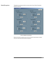
FuturePlus Systems Corporation
FS4405 PCI Express State
Analysis Preprocessor
User Manual
For use with Tektronix Logic Analyzers
Revision – 1.4
Copyright 2007 FuturePlus Systems Corporation
FuturePlus is a registered trademark of FuturePlus Systems Corporation
How to reach us .................................................................................................... 4
Product Warranty ................................................................................................. 5
Limitation of Warranty............................................................................................... 5
Exclusive Remedies ................................................................................................................5
Assistance ..................................................................................................................... 5
Introduction .......................................................................................................... 6
How to Use This Manual............................................................................................. 6
Definitions .................................................................................................................... 6
Analyzing the PCI Express Bus ........................................................................... 7
Accessories Supplied.................................................................................................... 7
Minimum Equipment Required ................................................................................. 7
Probing System Overview..................................................................................... 8
Front Panel................................................................................................................. 10
FS4405 Probing Cables ............................................................................................. 11
Interposer Probing FS1034/5/7 .............................................................................................12
Flying Lead Probing (FS1036 cable assembly) ....................................................................13
ExpressCard Probing (FS1033 Interposer assembly) ..........................................................14
Installing your Software for the First Time ............................................................ 15
Connecting the Tektronix logic analyzer to the FS4405 ........................................ 16
Loading system files................................................................................................... 17
Offline Analysis.......................................................................................................... 18
Probe Manager Application ..................................................................................... 19
Probe Configuration..............................................................................................................22
Packet Recognizers ...............................................................................................................24
Filtering.................................................................................................................................29
Log File.................................................................................................................................31
State Analysis...................................................................................................... 32
The PCI Express Protocol Disassembler Software................................................. 32
Labels (PCIe) ............................................................................................................. 33
Additional Bits (PCIe) ............................................................................................... 34
Labels (10b)................................................................................................................ 36
Triggering................................................................................................................... 37
Acquiring Data........................................................................................................... 38
10b Mode .................................................................................................................... 40
Debug .......................................................................................................................... 40
Finding the first Idle Characters in 10-bit Mode:..................................................................41
The Disassembler Display ......................................................................................... 42
Transaction Viewer ............................................................................................ 43
2
General Information .......................................................................................... 45
Characteristics ........................................................................................................... 45
Standards Supported .............................................................................................................45
Power Requirements .............................................................................................................45
Logic Analyzer Required ......................................................................................................45
Number of Probes Used ........................................................................................................45
Logic Analyzer State Clock Frequency ................................................................................45
Environmental Temperature .................................................................................................45
Altitude .................................................................................................................................45
Humidity ...............................................................................................................................45
Testing and Troubleshooting ................................................................................................45
Servicing ...............................................................................................................................45
Signal Connections .................................................................................................... 46
LAI Bit Definitions for a Single Direction x1, x2, x4 Link PCIe mode ...............................46
LAI Bit Definitions For a Single Direction x8 Link PCIe mode .........................................47
The clock is on B1 bit 16. .....................................................................................................47
LAI Bit Definitions for a Single Direction x2, x4 Link 10b mode ......................................48
LAI Bit Definitions For a Single Direction x8 Link 10b mode ...........................................49
3
How to reach us
For Technical Support:
FuturePlus Systems Corporation
36 Olde English Road
Bedford NH 03110
TEL: 603-471-2734
FAX: 603-471-2738
On the web http://www.futureplus.com
For Sales and Marketing Support:
FuturePlus Systems Corporation
TEL: 719-278-3540
FAX: 719-278-9586
On the web http://www.futureplus.com
FuturePlus Systems has technical sales representatives in several major
countries. For an up to date listing please see
http://www.futureplus.com/contact.html.
4
Product Warranty
This FuturePlus Systems product has a warranty against defects in material and
workmanship for a period of 1 year from the date of shipment. During the warranty
period, FuturePlus Systems will, at its option, either replace or repair products proven to
be defective. For warranty service or repair, this product must be returned to the factory.
Due to the complex nature of the FS4405 and the wide variety of customer target
implementations, the FS4405 has a 30 day acceptance period by the customer
from the date of receipt. If the customer does not contact FuturePlus Systems within
30 days of the receipt of the product it will be said that the product has been accepted
by the customer. If the customer is not satisfied with the FS4405 they may return the
FS4405 within 30 days for a refund.
For products returned to FuturePlus Systems for warranty service, the Buyer shall
prepay shipping charges to FuturePlus Systems and FuturePlus Systems shall pay
shipping charges to return the product to the Buyer. However, the Buyer shall pay all
shipping charges, duties, and taxes for products returned to FuturePlus Systems from
another country.
FuturePlus Systems warrants that its software and hardware designated by FuturePlus
Systems for use with an instrument will execute its programming instructions when
properly installed on that instrument. FuturePlus Systems does not warrant that the
operation of the hardware or software will be uninterrupted or error-free.
Limitation of
Warranty
The foregoing warranty shall not apply to defects resulting from improper or inadequate
maintenance by the Buyer, Buyer-supplied software or interfacing, unauthorized
modification or misuse, operation outside of the environmental specifications for the
product, or improper site preparation or maintenance. NO OTHER WARRANTY IS
EXPRESSED OR IMPLIED. FUTUREPLUS SYSTEMS SPECIFICALLY DISCLAIMS
THE IMPLIED WARRANTIES OF MERCHANTABILITY AND FITNESS FOR A
PARTICULAR PURPOSE.
Exclusive Remedies
THE REMEDIES PROVIDED HEREIN ARE BUYER’S SOLE AND EXCLUSIVE
REMEDIES. FUTUREPLUS SYSTEMS SHALL NOT BE LIABLE FOR ANY DIRECT,
INDIRECT, SPECIAL, INCIDENTAL, OR CONSEQUENTIAL DAMAGES, WHETHER
BASED ON CONTRACT, TORT, OR ANY OTHER LEGAL THEORY.
Assistance
Product maintenance agreements and other customer assistance agreements are
available for FuturePlus Systems products. For assistance, contact Technical Support.
5
Introduction
How to Use This
Manual
Definitions
This manual is organized to help you quickly find the information you need.
•
Analyzing the PCI Express Bus chapter introduces you to the FS4405 and lists
the minimum equipment required and accessories supplied for PCI Express bus
analysis.
•
The State Analysis chapter explains how to configure the FS4405 to perform state
analysis on your PCI Express bus.
•
The Transaction Viewer chapter is a brief overview of this application software that
integrates with the FS4405 Protocol Decoder.
•
The General Information chapter provides information on the operating
characteristics, and cable header pinout for the FS4405 probe.
The following terms are used to describe aspects of the PCI Express bus:
•
Channel - One differential signal (2 wires).
•
PCIe Lane - A pair of differential signals running in opposite directions (4 wires).
•
PCIe Link - A bidirectional interface made with two sets of unidirectional signals. A
Link consists of 1, 2, 4, or 8 lanes.
•
Link - One direction of a PCIe link. The FS4405 handles 1 or 2 links at a time,
independently. This supports probing of both directions of a PCIe link, or probing of
a pair of unrelated one-direction links. Links may be merged when displayed on the
logic analyzer.
•
Lane - One direction of a PCIe lane.
6
Analyzing the PCI Express Bus
This chapter introduces you to the FS4405 preprocessor and lists the minimum
equipment required for PCI Express Bus analysis.
The FS4405 is a High Speed, Flexible Serial bus State Analysis preprocessor. It is
designed to handle two directions of a link, or a single direction from each of two
unrelated links, using two link-processors (A and B), at lane widths of 1, 2, 4 or 8. The
preprocessor can connect to the PCI Express target by a number of different means,
including full and half-size midbus probes, x4 slot, x1 slot, x8 slot and ExpressCard
interposers, or flying leads. The preprocessor itself is controlled by the Probe Manager
software, which runs under Windows and communicates with the probe via a USB
cable.
The FS4405 “snoops” a PCI Express link without significantly degrading its signal
integrity. The high speed serial signal is deserialized and processed for packet
identification by the FS4405 before being sent to the logic analyzer connections.
Additionally, the preprocessor provides trigger, filtering, and packet recognition
functions. The disassembler software running on the logic analyzer provides information
regarding the transactions within the captured traffic, and the Transaction Viewer
provides a system level view of these transactions.
Accessories
Supplied
Minimum Equipment
Required
The FS4405 product consists of the following accessories:
•
The FS4405 preprocessor, power supply and cable, Protocol Disassembler,
FS1160, Tek Transaction Viewer, and Probe Manager applications on CD. A USB
cable is provided for connecting the FS4405 probe to the Windows based machine
that the Probe Manager is loaded on.
“WARNING – If the unit is not used as specified by the manufacturer, the
overall safety will be impaired.”
“WARNING – Only use power supply provided with the unit which is
manufactured by Lambda, P/N DT70PW050P.”
•
This User Manual and the Tek TV Manual on CD and Quick Start sheet.
The minimum equipment required for analysis of a PCI Express Bus consists of the
following equipment:
•
Tektronix TLA7AAx or TLA 7NAx analysis frame with the TLA7AA1/TLA7NA1
modules or better
•
An FS4405 probing cable
•
A PCI Express target bus. It is STRONGLY recommended that the user review and
apply the probing guidelines described in the FuturePlus Systems application note
“Logic Analyzer Probing Design Guide for the FS440x” when planning for use of the
probe on any target system.
7
Probing System Overview
The architecture of the FS4405 PCI Express preprocessor and the design of the
PCI Express link to be probed should both be thoroughly understood before
attempting to use the probe.
The following is a general outline of the steps to be taken when probing a new
link. Read the following pages for more specific information.
The FS4405 probe requires the understanding and correct set-up of 4 different
systems before a trace should be taken.
1. Probe Manager software. This software is identified as Probe Manager.exe and
is on the CD that comes with the FS4410. Additionally, there is a folder within
this CD that contains all the necessary USB drivers that your Windows system
requires. When Windows searches for the USB drivers to load during the first
connection of the FS4410, Windows MUST be directed to load the drivers
from this CD in the system or the proper USB drivers will not load. In some
cases it may necessary to temporarily disconnect the Windows system from the
local network to insure that Windows does not automatically default to getting
the drivers from the Internet. If the correct USB drivers are not loaded the user
will see a Windows error (“Unable to load DLL”) as soon as the “Run” button is
used.
NOTE: The Microsoft .NET Framework must be on the system for the Probe
Manager application to load properly.
2. FS4405 probe. This preprocessor requires its own DC power supply which is
provided. Additionally, this probe is completely initialized, set-up and controlled
by the Probe Manager software that resides on a Windows based system
(either stand alone PC or TLA7xxx logic analyzer). All communication to the
FS4405 probe is by means of the USB port on the PC (or logic analyzer).
Improper or incomplete installation of either the correct USB driver or the Probe
Manager software will prevent operation of the FS4405.
3. Tektronix Logic Analyzer. The files for the TLA7xxx analyzer (FS1160) are on a
CD. TLA Disassembler files Install these files as required and follow the
instructions for logic analyzer module (card) interconnections and logic analyzer
connections to the FS4405 probe.
4. PCI-Express target platform. There are a number of different probing options,
including mid-bus probe, interposer, flying lead, etc. There are also a wide
variety of PCI-E link implementations besides widths of x1, x2, x4, x8, etc. There
are protocol attributes such as lane inversion, data scrambling, lane reversal,
and spread spectrum that need to be defined in the Probe Manager in order for
the probe to capture data properly.
8
It is strongly recommended that the user methodically proceed in the following
manner when setting up the probe. There is more detail on each step in this
manual.
1. Load the Probe Manager software and (FS1160) on the PC and/or logic
analyzer. Leave the CD in the system for access to the USB drivers.
2. Configure (merge) the logic analyzer cards as required, and run the Tektronix
Logic analyzer’s internal diagnostics on the cards. If the analyzer passes then
make the appropriate target probe connections to the FS4405 probe.
3. Connect the appropriate probing cable(s) to the target system, power up the
probe. This may result in a Windows dialog searching for the “FTDI FTD2XX”
USB drivers; direct it to the Probe Manager CD. Check the Windows Device
Manager to make sure that it loaded properly.
4. Open up the Probe Manager application and select the appropriate settings for
the probe cable being used and the PCI-Express link. Check that the expected
Pad assignments for the probed link show green. For the first capture turn off all
the filters.
5. If the FS4405 probe LEDs are all Green and the first trace file captured on the
logic analyzer has no error messages then it is a good indication that all initial
settings are correct.
6. A link showing Signal LED green and Data LED orange constantly, needs
settings for link width, lane reverse or lane inversion adjusted in the Probe
Config window.
7. A link showing Signal LED orange or red may have a problem with the
reference clock connection, or need settings for Internal/External reference
clock adjusted in the Probe Config window. More information on link signal
status can be seen in the Log File window.
9
Front Panel
The connections and features of the FS4405 probe include:
•
DC input for provided external AC to DC power supply (please note that the use
of any other power supply voids the warranty on the FS4405), On/Off switch
and USB connections to the Windows PC/TLA7xxx where the Probe Manager
software will be loaded.
•
Link Probe cable connection for any 1 of the different probing cables and
Reference Clock probe cable connections.
•
Logic Analyzer probe 90 pin pod connections. A1 – A4 are connections for 1
Link Processor, and B1 – B4 are for the other Link Processor.
•
Reference Clock Probe Cable is permanently attached to the FS4405.
•
LED indication of probe power on and Link status. For each link there is a pair
of LEDs which have the following states:
Link A or B
Signal LED
color
Green
Link OK
Link A or B
Data LED
color
Green
Dark
Loss of Signal
Dark
Orange
Data Invalid (8b10b error)
Orange
Red
Receiver Fault
Red
Meaning
Meaning
Data clocking Into Analyzer
No Data clocking into
Analyzer
Any Error: 8b10b, Align,
Framing, Idle
Processor Clock Error
10
FS4405 Probing
Cables
The FS4405 PCI Express probe can be configured with a wide variety of different
probing cables dependent on what the user requires:
FS1031
Full size midbus footprint probe cable for x1, x2, x4
FS1032
½ size midbus footprint probe cable for x1, x2, x4, x8
FS1033
ExpressCard Interposer probe cable with reference clock buffer
FS1034
x1 slot Interposer probe cable
FS1035
x4 slot Interposer probe cable
FS1036
Flying lead probing cable for x1, x2, x4, x8
FS1037
x8 slot interposer cable (requires 2 FS4405 probes)
FS1038
Full size midbus footprint probe cable for x8 (requires 2 FS4405 probes)
FS1039
Full size midbus footprint probe cable for x8 (requires 2 FS4405 probes)
Cables FS1038 and FS1039 can also support x1, x2, x4 probing.
Cables FS1038 and FS1039 differ in their pinouts, the FS1039 better supports the
routing of all lanes on the same surface layer.
The “PCI Express Probing Design Guide for the FS440X” provides specific information
on the successful application of midbus probing and also details general requirements
for the Reference Clock signal and other aspects of the link to be probed. The FS4405
manual assumes that the user is familiar with this information and has applied it.
The cable should be attached to the FS4405 and carefully secured with the 2 captive
fasteners on the cable. The probing end should be attached to the target either by
screwing into the retention module (midbus probe) or inserting the Interposer into the
slot being probed. Use of the flying lead probe requires careful installation and
mechanical support of special axial leaded “RF-resistors”.
Note that use of the external Reference Clock is required when:
•
Spread Spectrum modulated clocking is occurring.
•
The target transmitter frequency is not within 100 ppm of nominal (even though
the PCIe standard allows 300 ppm deviation from nominal)
•
When the probe is operated in 10b mode (10-bit undecoded mode).
•
Only Reference Clock A is supported. Both links being probed must use the
same external Reference Clock.
11
Interposer Probing
FS1034/5/7
Due to the source terminated nature of the Reference Clock used in PCIe it is difficult to
acquire a quality signal at a mid-point of the Reference Clock trace, which is where the
Interposer probe sees it. In order to provide a high quality signal at the Interposer
probing point these probes (FS1034/5/7) incorporate a PCIe Reference Clock buffer
chip which serves to terminate this signal and then re-transmit it to both the target board
and to a 3 pin connector (JR1) on the Interposer that can be used to connect the Ref.
Clk cable from the FS4405 probe.
The Reference Clock Buffer chip can be operated in two modes: By-Pass or PLL.
FuturePlus recommends that the Interposer probe be used in By-Pass (BP) mode. If
used as a PLL it could create dynamic tracking error between the PLL used on the
system board and the PLL function on the interposer during SSC operation. It is
possible to use the PLL function to reduce jitter in the Reference Clock. This would
require moving the JR2 jumper from connecting the center and right hand pins to
connection the left hand and center pins. Additional control of the PLL mode can be
provided by changing the bandwidth of the PLL from Low to High by moving the jumper
at JR3. This BW function is only active when the device is in PLL mode.
The proper recommended shunt location is shown by a dashed line below:
12
Flying Lead Probing
(FS1036 cable
assembly)
The FS1036 flying lead cable assembly allows the FS4400 probe to connect to
components on the target board by means of directly soldering a flex pcb to a
component or feature on the target pcb, then connecting the header on the flying lead
cable to the other end of the flex pcb.
A few general guidelines about the use of the flying lead cable
1. There is an instruction booklet with the FS1036 cable that provides detail on
how to solder the flex pcb to your board. Refer to this document.
2. Polarity matters. Makes sure you know how the + and – sides of the signal are
connected. Adjustment to polarity can be made in the Probe manager.
The FS1036 flying lead cable has 8 pairs of channel connectors which are labeled A-G
for up to 4 channels of a link and B-H which can be used for another link.
Make the appropriate cable and channel selections in the Probe manager before taking
any probe measurements.
13
ExpressCard Probing
(FS1033 Interposer
assembly)
The FS1033 is a cable assembly that includes a slot interposer for an ExpressCard/34
slot. The interposer is made to be of sufficient length to use without having to remove
the covers on a target platform. As specified by the PCMCIA organization the
ExpressCard link works as either an x1 PCI Express module or as a USB2.0 module.
The FS1033 is a passive interposer of all signals except for the REF CLK, which is rebuffered appropriately and sent to both the ExpressCard module connector and to a
Reference Clock header for use with the FS4405 probe.
To provide additional functionality, probing pads are provided on the slot interposer for
all the ExpressCard signals besides PET/Rp/n (both directions of the x1 lane width
links). These points are clearly labeled in the silkscreen as shown below.
Probing USB with the FS1033
This can be done by using the FuturePlus Systems FS4120 USB2.0 probe and
using custom pigtail cables soldered to the pads at R17 and R18. Please contact
FuturePlus Systems for these cables.
In many cases the ExpressCard module is not “hot-pluggable”, the FS1033 will have to
be interposed between the target and the module before powering up the system. The
REFCLK signal is provided at JR1 for use with the FS4405 probe’s cable. The x1 PCI
Express signals are cabled to a standard FS4405 probe connector. Make sure all these
connections are made before powering on the system or the probe.
14
Installing your
Software for the First
Time
The following outlines the software installation procedure when using the probe for the
first time. Please do not attach the probe to the analyzer or computer that will be
controlling the probe until told to do so.
1. Place the software CD that came with the product into the logic analyzer or
computer that you will be installing the software on. In the case of a machine
that does not have a CD drive, the machine will either have to be put on a
network and the files loaded remotely or the CD files can be transferred from a
USB drive.
2. Navigate to the installation CD using Windows explorer and click on the
following files. Follow the instructions on the screen to install.*
•
FS1160.exe PCIe Protocol Decoder
•
FPSystems Disassembler.exe – This may already be installed if your
system has a previously installed FuturePlus product.
•
FS1150.exe (Transaction Viewer)
•
FS44xx Probe Manager.exe
3. Once all the above files have been installed, connect the FS4405 to the
analyzer/computer via the USB port. Power on the FS4405 probe.
4. The found new hardware wizard should appear the first time the probe is
attached and powered up. Select “no, not this time” when it asks if the
computer can go to Windows update to search for the software. Then select
next.
5. On the next screen select the Advanced option (not the Recommended) to
select from a specific list or location. select Next.
6. Select the CD-ROM drive to load the driver from; you do not have to select a
specific directory. Select next.
7. There may be a warning that comes up about Windows XP compatibility, ignore
this warning and continue with installation.
8. Click Finish to complete the installation.
Once all the previous steps have completed all necessary software as well as USB
drivers will be installed. This procedure only needs to be done on initial install. You
may now go to the desktop and click on the Probe manager icon to start the probe
manager.
*If you are installing on a PC to only control the FS4405 probe then you can omit the
installation of the FS1160.exe, FS1150.exe and FPSystems Disassembler Application,
but you must follow the rest of the steps.
For instructions on loading system files please refer to the section on loading system
files later in this manual.
15
Connecting the
Tektronix logic
analyzer to the
FS4405
The FS4405 is designed to enable the user to connect the FS4405 to the widest
possible range of Tektronix logic analyzer modules (cards). The FuturePlus Systems
FS1055 cable is designed to attach to the 90 pin connectors on the FS4405 and to the
TLA7A/N connector on the other end. Each FS1055 connects 2 FS4405 90 pin pods (17
channels each) to 1 TLA card input (34 channels)
Connect the logic analysis cards to the FS4405. The table below explains how to
connect TLA7AA4 card to the FS4405.
FS4405
Comment
C0:C3
A1
A2
Clock
D0:1, A0:1
A3
A4
D2:3, A2:3
B1
B2
E0:3
B3
B4
Logic Analyzer
Based on the probing needs install the appropriate modules into the Tektronix logic
analyzer and remove any adapter cables that may be attached to the module cables.
When probing 2 directions of x1, x2, x4 links, or a single direction of an x8 link, the
FS4405 drives 8 pods of signals (4 FS1055 cables) to the logic analyzer. When probing
a single direction of a x1, x2 or x4 link, the FS4405 drives 4 pods of signals (2 FS1055
cables) to the logic analyzer.
It is important before you load a system file you initiate a self test on all your
modules installed in your logic analyzer to insure all modules are working
properly.
16
Loading system files
You can access the system files by clicking on the FS1160 folder that was placed on the
desktop. When you click on the folder it should open up to display all the system files to
choose from. If you put your mouse cursor on the name of the file a description will
appear telling you what the setup consists of, once you choose the system file that is
appropriate for your configuration the TLA operating system should execute.
The analyzers supported by the FS4405 system files are for theTLA7xxx cards
PE160-1 – x1 2 way 10b analysis. Requires 1 FS1055 cable and 34 logic analysis
channels
PE160-2 – x2 and x4 2 way 10b analysis. Requires 4 FS1055 cables and 136 logic
analysis channels.
PE160_3/4 – x8, 1 way 10b analysis. Requires 3 FS1055 cables and 102 logic analysis
channels. 1 system file is used for each direction on the x8 link.
PE160_5 – x1, x2, x4 2 way PCI Express analysis. Requires 4 FS1055 cables and 136
logic analysis channels.
PE160_6/7 – x8, 1 way PCI Express analysis. Requires 3 FS1055 cables and 102 logic
analysis channels. 1 system file is used for each direction on the x8 link.
When probing 2 directions of a x8 PCIe link the TLA67xx cards do not have to be
merged.
17
Offline Analysis
Data that is saved as a *.tla file, can be imported into the TLA7xxx environment for
analysis. You can do offline analysis on a PC if you have the TLA7xxx operating system
installed on the PC, if you need this software please contact Tektronix.
Offline analysis allows a user to be able to analyze a trace offline at a PC so it frees up
the analyzer for another person to use the analyzer to capture data.
In order to view decoded data offline, after installing the TLA7xxx environment on a PC,
you must install the FuturePlus software. Please follow the installation instructions for
“Setting up TLA7xxx analyzer”. Once the FuturePlus software has been installed and
licensed follow these steps to import the data and view it.
From the desktop, double click on the Tektronix TLA icon. When the application comes
up there will be a series of questions, answer the first question asking which startup
option to use, select Continue Offline. On the analyzer type question, select Cancel.
When the application comes all the way up you should have a blank screen with a menu
bar and tool bar at the top.
Open the .tla file using the File, Load System menu selection and browse to the desired
.tla file.
After the data has been imported you must load the TLA disassembler before you will
see any decoding. To load the disassembler select Tools from the menu bar, when the
drop down menu appears select FPSSystems decoder, then choose the name of the
protocol for your particular product when the disassembler window appears. You need
to choose a disassembler and a data source for each direction. The figure below is a
general picture.
18
Probe Manager
Application
The Probe Manager software can be found as the FS44xx Probe Mgr.exe file on the CD
provided in the Documentation package. Insert the CD into the computer that will be
used to control the FS4405 probe. This computer must have a USB connection. Using
Windows File Manager, select the FS44xx Probe Mgr.exe file and double-click it, which
initiates the installation software on the computer and places an icon on the desktop.
Follow the directions that follow including agreeing to the license terms, once the
software installation is complete click on finish. To start the program manager simply
double click its desktop icon.
The Probe Manager application detects all FS44xx probes that are connected to the
USB bus and allows the user to select which probe will be controlled by the current
instance of the Probe Manager application from the initial screen as seen below.
19
The initial screen is followed by the Protocol Selection screen, in which the user selects
the protocol the FS4405 probe will be associated with.
Once the protocol has been selected, the application displays the Main dialog as seen
below:
The user configures and controls the probe from the main form. The form is composed
of a menu bar, a tool bar and a status message bar. The menu bar provides options
that allow the user to configure and run the probe. The tool bar provides options to
configure the probe and the status bar displays the probes current status and/or any
errors that may have been encountered. Error messages displayed in the status bar are
also logged in the Log Form if logging is enabled.
The menu bar contains the following options:
File
•
Open Config File – Displays a open file dialog in which the user may
navigate to and open the file contains a previous
session’s saved probed settings.
20
•
Save As - Displays a save file dialog in which the user may specify
where a probe settings system file may be saved.
•
Exit – Shut down the application.
•
Modify Title String – Allows the user to specify the title string that
appears in all sub-dialog’s title bar. This is helpful when running
multiple probes.
Edit
Run/Stop
• Run Probe Mgr – Running the probe with the current settings. This is an
alternative to clicking the tool bar Run button.
•
Stop Probe Mgr - Stop the probe. This is an alternative to clicking the
tool bar Stop button
Upgrade
• Upgrade – Upgrade one of four protocol specific FPAG configurations.
Help
•
About – Display version numbers for the Probe Manager application
and FPGA configuration.
The application displays up to five sub-dialogs in a modeless manner. The sub-dialogs
are used to configure the FS4405 probe.
The five sub-dialogs are:
•
•
•
•
Probe Configuration – Covers the type of probe cable used and basic aspects of
the link being probed.
Packet Recognizers – Set up the 3 Packet Recognizers provided per Link,
which may be used to specify packet header based
triggering parameters.
Filters – Allows the user to specify the types of packets to be filtered
Log Entries – Run time probe status.
21
Probe Configuration
The Probe Configuration dialog provides the user with ability to configure the probe and
monitor signal activity on each channel.
-Probe Config X1 X2 X4 Dialog
Probe Config X8 Dialog
22
The functions provided on these forms include:
•
Selection of the Probing Cable type, Link width, and pad arrangement (referring
to the arrangement of lanes on the mid-bus probe pads; see the “PCI Express
Probing Design Guide for the FS440X” for more specific information).
•
The Pad Assignment graphic shows the assignment of logical lanes as a result
of user selections, and also represents the physical layout of mid-bus pads.
The FS4405 processes channels from the left column in link-processor A and
from the right column in link-processor B.
•
Next or Previous buttons scroll through the various types of currently supported
pad assignments (see the “PCI Express Probing Design Guide for the FS440X”
for details of supported pad assignments).
•
Lane Inversion can be selected on an individual channel basis by clicking the
INV button associated with each lane.
•
While the probe is stopped, signal activity indicators are provided on each
channel. Signal presence is indicated by an up-down arrow symbol and a lack
of signal presence is indicated by a flat horizontal line symbol.
•
Selection of Lane Reversal on each link.
•
Selection of Data Descrambling on each link.
•
Reference Clocking choices are to use the FS4405 Internal reference on both
links (these links must have 100 PPM frequency accuracy) or use External
Reference Clock signal(s) from the target platform, via the FS4405 external Ref.
Clock cable. For PCIe, the expected frequency is 100 MHz. If necessary, PCIe
probing with a 125 MHz reference clock is supported by the FS4405, contact
FuturePlus Systems for details.
•
Selection of external reference clock source for link B: same as A (common
clock, uses the Reference Clock A probe input), or different (distinct clock, uses
Reference Clock B probe input).
•
Selection of Spread Spectrum clock processing mode. Activate only when
spread spectrum modulation is in use (requires external reference clock).
•
Selection of Active-State Power Management (ASPM) mode. Activate when
the target link state is repeatedly switching between normal operational (L0) and
shallow power saving (L0s) states. Activating this control allows the probe
hardware to decode traffic starting early in the Fast Training process, usually
within the first few FTS Ordered Sets transmitted when the link returns to L0
state. Activating this control comes with a small price in that LOS status for the
active lanes is not available while the probe is running. There are two
consequences of running in ASPM mode:
•
o
Signal loss is reported on LEDs and in the Log File as other types of
errors (that result from signal loss).
o
LOS status bits can not be used for triggering the logic analyzer, and
are not useful in the listing, because they are forced to 0 (only while
running and only on active lanes).
Selection of Toggle mode. When activated, the probe output signals to the logic
analyzer pods and the link status LEDs are toggled.
23
Packet Recognizers
This dialog form provides the ability to setup the three 24-byte Pattern Recognizers
provided on each link.
Pattern and Mask X1,X2,X4 Dialog
Because the pattern recognizers look at the first 24 bytes of each packet (or ordered
set), they are also referred to as packet recognizers.
24
Pattern and Mask X8 Dialog
The Packet Recognizer dialog allows a user to specify the packet recognizer pattern.
The x1, x2 and x4 Packet Recognizer dialog allows the user to enter up to 6 patterns (3
on link A and 3 on link B). In x8 mode, the user can enter up to 3 patterns. In x8 mode,
packets are detected if they start on lane 0 or lane 4.
The pattern is entered via a sub-dialog that is displayed after the user has clicked one of
the six Edit buttons. There are three sub-dialog forms, one for Ordered Sets, one for
DLLP packets, and one for TLP packets as shown below.
25
DLLP Pattern and Mask Dialog
26
TLP Pattern and Mask Dialog
Ordered Set Pattern and Mask Dialog
27
The DLLP, TLP and Ordered Set sub-dialog screens are designed such that the
minimum numbers of fields are specified to form a valid packet. Fields displaying X’s
will be masked out. All reserved fields will be masked into the pattern.
Every field is validated as the user is entering the hex values. The user may enter any
combination of X’s and hex digits into each field. Each field may be edited in binary
form by right clicking the mouse key, at which point the contents of the field are
displayed in binary format in a separate window. When the user applies the binary
values (by clicking the Accept button), the binary value is converted to a hex
representation and displayed in the pattern dialog. Field Hex digits that are partially
masked will be displayed with a “$” character.
Binary Editor Dialog
The packet recognition setups are created via sub-dialogs that are displayed whenever
the user selects a packet type (via the radio buttons for each link pattern) and clicks the
Edit button.
The pattern is edited if the user clicks the Apply button on the packet-specific subdialogue form. If edited, the packet type string is displayed in a light blue color.
Once edited, the pattern may be cleared by clicking the Clear button. This will inactivate
the recognizer.
Pattern Recognizers are used to trigger the logic analyzer whenever a specific packet or
ordered set pattern is encountered. Each Pattern recognizer outputs a PAT_REC flag
to the logic analyzer that pulses high during the 1st state of each packet.
Pattern recognizers may also be used as filters.
The Pattern Recognizer examines the first 24 bytes of each packet. Recognizers are
setup by the Probe Manager with a match pattern and a separate mask pattern, giving
the user control over the comparison, bit by bit.
The probe must be stopped before editing patterns.
You must always restart the probe by pressing the green run button on the main window
so the new values will be written to the probe hardware.
28
Filtering
The Filter dialogue page provides the user with a comprehensive suite of predefined
filter functions to apply to either Link.
Filter types include all TLP and DLLP packets, Ordered Sets, Traffic Class, Virtual
channel, and special signal states.
Additionally, filters are provided to Pass or Drop packets that have been recognized by
the three packet recognizers.
Filters X1,X2,X4 Dialog
Filtering is done in real time by the FS4405 hardware.
Filtering out unwanted traffic such as Logical Idles can extend the storage capabilities of
the logic analyzer. Filtering out irrelevant bus traffic can help users focus on specific
packets of interest.
To filter out any particular traffic type, click on the appropriate box so a √ appears and
click apply. You must restart the probe by pressing the green run button so the new
values will be written to the probe hardware.
Use Link A and Link B buttons to switch to the other link’s filter.
Filtering can also be done using any combination of packet header bits, via the Pattern
Recognizers. The “PR Drop” filters drop the recognized packets. The “PR Pass” filters
over-ride all other filters, and force recognized packet to be clocked into the analyzer.
29
Filters X8 Dialog
Filtering is done in real time by the FS4405 hardware.
Filtering out unwanted traffic such as Logical Idles can extend the storage capabilities of
the logic analyzer. Filtering out irrelevant bus traffic can help users focus on specific
packets of interest.
To filter out any particular traffic type, click on the appropriate box so a √ appears and
click apply. You must restart the probe by pressing the green run button so the new
values will be written to the probe hardware.
Filtering can also be done using any combination of packet header bits, via the Pattern
Recognizers. The “PR Drop” filters drop the recognized packets. The “PR Pass” filters
over-ride all other filters, and force recognized packet to be clocked into the analyzer.
30
Log File
The status of the probe, and the link under test, can be seen in this tab page.
Log File Dialog
Once started, logging continues even if the probe is stopped and started, or if the log
window is closed and re-opened.
Once a probe has been stopped, the log entries can be written to a file of the user’s
choice by clicking the Write Log File button.
31
State Analysis
The PCI Express
Protocol
Disassembler
Software
This chapter explains how to use the FS4405 to perform state analysis. The system file
sets up the format specification menu of the logic analyzer for compatibility with the
output of the FS4405. Load the appropriate system file located in the FS1160 shortcut
located on the desktop.
To load the disassembler select Tools from the menu bar, when the drop down menu
appears select FPSystems Disassembler. Load the PCI Express Protocol
Disassembler software (FS4405) by selecting the correct protocol (PCIe) and data
source for each direction, and press the decode button. If you are analyzing 2 different
protocols simply choose the data source and direction and the correct protocol for the
data source.
32
Labels (PCIe)
Besides de-serializing the data stream for the logic analyzer, the FS4405 generates a
number of identification and control bits that are used by the Protocol Decoder and
logic analyzer. These are also available to the user and can be used as described
Pre-defined Label
No.
of
Bits
VAB
DS
(Default Store Flag)
1
PSS
(Packet Sample State)
2
Definition/Usage
Collection of all flags for Inverse
Assembler usage.
1= Store this state 0 = Discard
This signal must be used for default
store qualification.
PSS[1] = Start of Packet flag
PSS[0] = End of Packet flag
Logic
Analyzer
Pod
Logic
Analyzer
Pod
x1, x2, x4
mode
x8 mode
A4[16]
(CLK)
B4[10]
(CLK)
A4[5:4]
B4[3:2]
NA
B4[4]
A4[0:3],
A3[16:15]
B4[1:0],
B3[16:13]
A4[13]
A4[11:9]
B4[8]
B4[7:5]
A3[6:0],A2[
16:14]
A2[16:7]
A2[13:4]
A2[6:0],
A1[16:14]
A2[3:0],A1[
15:10]
A1[13:4]
A1[9:0]
A1[3:0],
B4[16:11]
10=start, 01=end, 11= start & end
00=inside packet, ordered set or idle.
Unjust
1
Event_Code
6
Error
Pat_Rec_3
Pat_Rec_2
Pat_Rec_1
(Pattern Recognizers)
Lane0
1
3
10
Lane1
10
Lane2
10
Lane3
10
Use PSS[1] = 1 in conjunction with
Event_Code to detect each occurrence.
X8 only: When set, indicates a packet
beginning at lane 4 rather than lane 0.
Describes what type of packet, ordered
set, signal event or error event. Code is
held for duration of packet or ordered
set, except that probe-generated signal
and error events can over-write any state
except the start state. When start and
end coincide, the event code for the
starting packet is displayed. See next
page for a list of event code values.
1= This state includes an error
1= Packet recognized (pulsed for one
clock cycle). These are to be used for
logic analyzer triggering only. Do not
qualify with DS.
Logical Lane 0 Data
(spread data in x1 or x2 lane mode)
Bit 9 is Invalid flag, Bit 8 is Control flag
Logical Lane 1 Data
(spread data in x1 or x2 lane mode)
Bit 9 is Invalid flag, Bit 8 is Control flag
Logical Lane 2 Data
(spread data in x1 or x2 lane mode)
Bit 9 is Invalid flag, Bit 8 is Control flag
Logical Lane 3 Data
(spread data in x1 or x2 lane mode)
Bit 9 is Invalid flag, Bit 8 is Control flag
below.
33
Lane 4
10
Lane 5
10
Lane 6
10
Lane 7
10
Additional Bits
(PCIe)
Logical Lane 4 Data
(x8 mode only)
Bit 9 is Invalid flag, Bit 8 is Control
flag
Logical Lane 5 Data
(x8 mode only)
Bit 9 is Invalid flag, Bit 8 is Control
flag
Logical Lane 6 Data
(x8 mode only)
Bit 9 is Invalid flag, Bit 8 is Control
flag
Logical Lane 7 Data
(x8 mode only)
Bit 9 is Invalid flag, Bit 8 is Control
flag
NA
B3[11:2]
NA
B3[1:0],
B2[16:9]
NA
B2[8:0],
B1[15]
NA
B1[14:5]
The FS4405 generates a number of identification and control bits that are used by the
Protocol Decoder and logic analyzer. There are a few that don’t have pre-defined
labels, (other than being in the VAB label used by the Inverse Assembler).
These are also available to the user and can be used as described below.
Functional Name
No. of
Bits
Definition/Usage
ALIGNED
1
1 = multi-lane link is aligned
0 = lane deskew has failed
DATA PRESENT
[3,2,1,0]
4
LOS
[3,2,1,0]
4
Any LOS
1
(Exists in x1 x2 x4 mode only.)
1 = Lane data is present.
0 = Lane data is not present due to effects
of spreading x1 or x2 data across 4 lanes.
Lane-by Lane LOS bits.
(Provided in x1 x2 x4 mode only.)
1 = Loss of Signal in Lane
0 = Signal Detected or Lane not used
Composite LOS bit (all active lanes)
(Provided in x8 mode only.)
Logic
Analyzer
Pod
In x1 x2 x4
mode
Logic
Analyzer
Pod
In x8 mode
A4[14]
B4[9]
A3[14:11]
NA
A3[10:7]
NA
NA
B3[12]
34
Event Code label definitions (PCIe mode):
Event
Unknown (loss of frame synch)
Electrical Idle Signal Event
Beacon Signal Event
Link Alive Signal Event
Signal Logical Idle
Signal Compliance Pattern
Ordered Set TS1
Ordered Set TS2
Ordered Set Skip
Ordered Set FTS
Ordered Set Electrical Idle
TLP Memory Read
MRd
TLP Memory Read Locked
MRdLk
TLP Memory Write
MWr
TLP IO Read Request
IORd
TLP IO Write Request
IOWr
TLP Config Read Type 0
CfgRd0
TLP Config Write Type 0
CfgWr0
TLP Config Read Type 1
CfgRd1
TLP Config Write Type 1
CfgWr1
TLP Message
Msg
TLP Message with Data
MsgD
TLP Completion
Cpl
TLP Completion with Data
CplD
TLP Completion for Locked
CplLk
TLP Completion Locked Data
CplDLk
DLLP Ack
DLLP Nak
DLLP PM-Enter-L1
DLLP PM-Enter-L23
DLLP PM-Active-State-Req
DLLP PM-Request-Ack
DLLP Vendor-specific
DLLP InitFC1-P
DLLP InitFC1-NP
DLLP InitFC1-CPL
DLLP InitFC2-P
DLLP InitFC2-NP
DLLP InitFC2-CPL
DLLP UpdateFC-P
DLLP UpdateFC-NP
DLLP UpdateFC-Cpl
Error Unexpected K
Error Packet Ends Bad
Link Down Signal Event
Error Logical Idle
Error Invalid Symbol Decode
Error Unexpected LOS
Error Framing
Error Alignment (X8 mode only)
Error Control Column (X8 mode only)
Error TSID (X8 mode only)
Error TLP Decode (X8 mode only)
Error DLLP Decode (X8 mode only)
Event code
0x00
0x01
0x02
0x03
0x04
0x0C
0x05
0x06
0x07
0x08
0x09
0x10
0x11
0x12
0x13
0x14
0x15
0x16
0x17
0x18
0x19
0x1A
0x1B
0x1C
0x1D
0x1E
0x20
0x21
0x22
0x23
0x24
0x25
0x26
0x27
0x28
0x29
0x2A
0x2B
0x2C
0x2D
0x2E
0x2F
0x30
0x31
0x33
0x34
0x35
0x36
0x37
0x38
0x39
0x3A
0x3D
0x3E
35
Labels (10b)
Pre-defined Label
Align Flag
Any Invalid Error Flag
Besides de-serializing the data stream for the logic analyzer, the FS4405 in 10b Mode
generates a number of status bits that are available to the user and can be used for
triggering and analysis as described below.
No.
of
Bits
1
1
Definition/Usage
Logic
Analyzer
Pod
Logic
Analyzer
Pod
Logic
Analyzer
Pod
10-bit,
x1 mode
10-bit,
x2, x4
mode
10-bit,
x8 mode
(use B
pods for
other
link)
(use B
pods for
other
link)
NA
A1[0]
A4[4]
A4[3]
LOS [3,2,1,0]
4
Any LOS
1
Lane 0 Disparity Error
Lane 0 Invalid Decode Error
Lane0
Lane 1 Disparity Error
Lane 1 Invalid Decode Error
Lane1
1
1
10
1
1
10
1= Alignment of multi-lane link detected
1= This state includes an 8b10b code error
(either disparity error or decode error in any
active lane)
1= Corresponding lane Loss of Signal
0= Signal detect on lane
(x2 x4 mode only)
1= Loss of Signal detected in any active lane
0= Signal detected in all active lanes
1= Lane 0 data has incorrect 8b10b disparity
1= Lane 0 data is not a valid 8b10b code
Physical Lane 0 Data, 10-bit encoded
1= Lane 1 data has incorrect 8b10b disparity
1= Lane 1 data is not a valid 8b10b code
Physical Lane 1 Data, 10-bit encoded
Lane 2 Disparity Error
Lane 2 Invalid Decode Error
Lane2
1
1
10
1= Lane 2 data has incorrect 8b10b disparity
1= Lane 2 data is not a valid 8b10b code
Physical Lane 2 Data, 10-bit encoded
NA
NA
NA
Lane 3 Disparity Error
Lane 3 Invalid Decode Error
Lane3
1
1
10
1= Lane 3 data has incorrect 8b10b disparity
1= Lane 3 data is not a valid 8b10b code
Physical Lane 3 Data, 10-bit encoded
Lane 4 Disparity Error
Lane 4 Invalid Decode Error
Lane4
1
1
10
Lane 5 Disparity Error
Lane 5 Invalid Decode Error
Lane5
1
1
10
Lane 6 Disparity Error
Lane 6 Invalid Decode Error
Lane6
1
1
10
Lane 7 Disparity Error
Lane 7 Invalid Decode Error
Lane7
1
1
10
1= Lane 4 data has incorrect 8b10b disparity
1= Lane 4 data is not a valid 8b10b code
Physical Lane 4 Data, 10-bit encoded
(x8 mode only)
1= Lane 5 data has incorrect 8b10b disparity
1= Lane 5 data is not a valid 8b10b code
Physical Lane 5 Data, 10-bit encoded
(x8 mode only)
1= Lane 6 data has incorrect 8b10b disparity
1= Lane 6 data is not a valid 8b10b code
Physical Lane 6 Data, 10-bit encoded
(x8 mode only)
1= Lane 7 data has incorrect 8b10b disparity
1= Lane 7 data is not a valid 8b10b code
Physical Lane 7 Data, 10-bit encoded
(x8 mode only)
A2[15]
A2[14]
NA
A4[2:0]
A3[16]
NA
A1[15]
A3[15]
A2[13]
A1[14]
A1[13]
A1[12:3]
NA
NA
NA
A2[12]
A2[11]
A2[10:1]
A2[0]
A1[15]
A1[14:5]
NA
NA
NA
A3[14]
A3[13]
A3[12:3]
A3[2]
A3[1]
A3[0]
A2[16:8]
A2[7]
A2[6]
A2[5:0]
A1[15:12]
A1[11]
A1[10]
A1[9:0]
NA
NA
NA
NA
NA
NA
NA
NA
NA
NA
NA
NA
NA
NA
NA
NA
NA
NA
NA
NA
NA
NA
NA
NA
A1[4]
A1[3]
A1[2:0]
B4[16:10]
B4[9]
B4[8]
B4[7:0]
B3[16:15]
B3[14]
B3[13]
B3[12:3]
B3[2]
B3[1]
B3[0]
B2[16:8]
B2[7]
B2[6]
B2[5:0]
B1[15:12]
B1[11]
B1[10]
B1[9:0]
36
Triggering
The system files provide some logic analyzer based trigger set-ups that utilize the pre
defined symbols described earlier.
Remember to always use STORAGE for default storage, and use default storage to fill
memory. If you are analyzing only 1 direction you should change the group name
STORAGE to either A_DS or B_DS depending on which direction you are
analyzing, if you do not make this change the state listing may not show any valid
data. STORAGE is an OR of A_DS and B_DS, if one side is not being used the DS
bit may be held high which will fill the analyzer with invalid information.
The 6-bit probe-generated Event Code field makes it easy to trigger on particular packet
types. When triggering on Event Code always qualify it with:
•
DS =1 (Already included in pre-defined Event Code symbol definitions)
•
PSS[1] =1 (The start of packet flag).
The probe-generated Packet Recognizer flags (Pat_Rec_3,2,1) make it easy to trigger
on packets based on header or data bit patterns in the first 24 bytes of each packet.
These flags are always valid, pulse once at the start of each recognized packet, and do
not need any other bits to qualify them.
37
First, insure that the FS4405 probe is attached to its external power supply and powered
on, which would be indicated by a green Power On LED. Open up the Probe Manager
software and insure the appropriate selections are made and applied, finally make sure
that the probe is connected via the appropriate cable(s) to the target system.
Acquiring
Data
Once connected, with the link active, open up the Probe Config window and select cable
type, lane width, and reference clock options. Verify that lane activity indicators show
activity at the correct lanes. Run the probe and observe the LEDs.
If a link’s Signal LED is green but its Data LED is orange then there may be a need to
select different options for lane width, lane reverse or lane inversion in the Probe Config
window.
The FS4405 probe should show a green Signal LED of any Link being probed, as well
as a green or dark data LED.
Configure the analyzer trigger menu to acquire PCI Express data. Select RUN and, as
soon as there is activity on the bus, the logic analyzer will begin to acquire data. The
analyzer will continue to acquire data and will display the data when the analyzer
memory is full; the trigger specification is TRUE or when you select STOP.
Link status is communicated by a pair of LEDs as follows:
Signal LED State
Dark
Red
Orange
Green
Meaning
LOS (no signal on an active lane)
RX Fault: Lost Lock on Ref Clock, Lost
Synch on Data, FIFO over run or under run.
See Log for more information.
Invalid Symbol or Disparity Error
OK
Data LED State
Red
Orange
Green
Dark
Meaning
FPGA Lost lock on clock(s).
Probe needs to stop and run again.
Any Error: Invalid Symbol or Disparity Error,
Align, Framing, Idle.
OK, Data clocking into analyzer.
No Data (due to filtering or not running)
All transient events such as a single bit error, or a packet clocked into the analyzer, are
stretched to short visible pulses on the LEDs.
Observing Link Start-up:
When using Internal Reference clock, the probe can be run at any time, before or after
the target has powered up or link become active.
When using External Reference clock(s), the probe requires the target reference clock
to be active before the probe is run.
In all cases, links may be re-started, and target systems may be re-booted, while the
probe is running. This makes probing link initialization convenient.
Observing PCIe Link Activity in ASPM :
PCI-Express Active State Power Management (ASPM) protocol, allows links to
transition back and forth between active (L0) and low power states (L0s, L1, L2 etc).
38
The probe will follow links that go up and down:
•
When a link is constantly transitioning back and forth between active and low
power states, the Signal LEDs and the log file will report errors that can be
ignored.
•
The probe can follow Fast Training. If a link is transitioning between active (L0)
and shallow power saving (L0s), the probe will achieve very low N_FTS when
operated in ASPM mode, selected by clicking the “ASPM” checkbox on the
Config window before running the probe. This mode allows the probe to start
capturing data early during the Fast Training ordered sets.
Finding Stable PCIe Link Activity:
When a link is expected to perform initialization, set the analyzer to trigger on:
•
“Event Code = TS2 training set”
This assures the link is up and running because a PCIe device issues TS2 ordered sets
only after it has received valid TS1 ordered sets from the other direction.
Finding Link Startup During Fast Training:
When a link is expected to perform fast training, set the analyzer to trigger on:
•
“Event Code = FTS Ordered Set”
Finding the Start of Signal Activity:
Set the analyzer to trigger on:
•
“Event Code = Link Alive”
Another method is to trigger based on signal detection status (LOS = loss of signal).
Note this method can only be used when the probe is not setup for ASPM mode:
•
“Event Code = Beacon” (signal detected on lane 0)
•
LOS[0] goes low (for 1-lane operation)
•
LOS[1:0] goes low (all lanes signal detected in 2-lane operation)
•
LOS[3:0] goes low (all lanes signal detected in 4-lane operation)
•
ANYLOS goes low (all lanes signal detected in 8-lane operation)
Note: Some links startup cleanly (within 300 nS of de-assertion of LOS flag), but others
do not. The probe itself can not achieve lock quickly until it receives a stable signal and
a stable reference clock. Signal detection does not imply a valid serial data signal.
Signal detection (LOS status) is delayed relative to link data capture.
39
The FS4405 requires an external reference clock connection when used in 10b mode.
10b Mode
Debug
The LEDs operate as described previously.
Note: When using the FS4405 in 10-bit Mode, the user must select a Logic Analyzer
System file based on the lane width of the link being probed. The user must also select
the correct lane width in the Probe Config window.
The probe hardware does real-time, lane-based 8b10b error checking, lane deskew and
lane deskew checking. There are no filters or pattern recognizers provided in 10b
mode. Packets and ordered sets are detectable using the analyzer trigger capabilities,
looking for the values listed below. There is no disassembler; however there are predefined symbols that make packet boundaries visible in the state listing.
The following are some useful 10b symbol definitions for PCI-Express. All but the TSID
values are available pre-loaded in the lane data symbol tables for convenient setup of
triggers. Trigger on COM to find any ordered set. Trigger on FTS, SKP or IDL to find
specific ordered sets. Trigger on SDP to find DLLP packets. Trigger on STP to find
TLP packets. Remember there are usually two different possible codes representing
each character in 10-bit Mode.
COM
FTS
SKP
SDP
IDL
PAD
STP
END
EDB
TSID1
TSID2
K28.5
K28.1
K28.0
K28.2
K28.3
K23.7
K27.7
K29.7
K30.7
D10.2
D5.2
Value follows negative disparity
Value follows positive disparity
COM+
FTS+
SKP+
SDP+
IDL+
PAD+
STP+
END+
EDB+
TSID1
TSID2
COMFTSSKPSDPIDLPADSTPENDEDBTSID1
TSID2
0101_111100
1001_111100
0010_111100
1010_111100
1100_111100
0001_010111
0001_011011
0001_011101
0001_011110
1010_101010
1010_100101
17C
27C
0BC
2BC
33C
057
05B
05D
05E
2AA
2A5
1010_000011
0110_000011
1101_000011
0101_000011
0011_000011
1110_101000
1110_100100
1110_100010
1110_100001
1010_101010
1010_100101
283
183
343
143
0C3
3A8
3A4
3A2
3A1
2AA
2A5
Verify Setup in 10-bit Mode:
To verify correct lane reverse settings, make sure the SDP, STP characters appear on
the leftmost lane and the END characters appear on the rightmost lane.
To verify lane width settings, verify Data LED is green (checks for valid data on all lanes,
and the successful de-skew of active lanes). Observe a DLLP packet in the listing and
verify it consists of 8 consecutive bytes from SDP through END.
To verify correct lane inversion settings, check that the TSID (last 10 states of every
TS1 or TS2 ordered set) during training is hex 2AA or 2A5 and not 155 or 15A.
40
Finding Stable PCIe Link Activity in 10-bit Mode:
When a link is expected to perform initialization, set the analyzer to trigger on:
•
“Lane0 = TSID2 (2A5), 10 times Consecutively”
This detects TS2 ordered sets during link initialization. This assures the link is up and
running because a PCIe device issues TS2 ordered sets only after it has received valid
TS1 ordered sets from the other direction.
Finding Link Startup During Fast Training in 10-bit Mode:
When a link is expected to perform fast training, set the analyzer to trigger on:
•
“Lane0 = FTS+ or FTS-“
Finding the start of Signal Activity in 10-bit Mode:
Set the analyzer to trigger on signal detection status (LOS = loss of signal). Note this
method can only be used when the probe is not setup for ASPM mode:
•
ANYLOS goes low (all lanes signal detected)
Note: Some links startup cleanly (within 300 nS of de-assertion of LOS flag), but others
do not. The probe itself can not achieve lock quickly until it receives a stable signal and
a stable reference clock. Signal detection does not imply a valid serial data signal.
Signal detection (LOS status) is delayed relative to link data capture.
Finding the first Idle Characters in 10-bit Mode:
With scrambling assumed to be occurring, the first 2 idle data words following TS1/TS2
training sets will be either, (depending on disparity):
• 2CD followed by 161
• 10D followed by 15E
Note: Idle data might not immediately follow TS1/TS2, there may be Skip Ordered Sets
or DLLPs
41
The
Disassembler
Display
Captured data is as shown in the following figure. The below figure displays the
protocol decode.
The FS4405 Disassembler (FS1160) will perform the following functions:
♦
♦
Decode all PCI Express command and cycle types
Color code the transaction type. The colors used by the software are as follows:
o Ordered Sets: Orange
o TLP Packets: Green.
o DLLP: Purple
o Error: Red
o Signal (Probe generated packets): Yellow
o Unknowns: White
42
Transaction Viewer
The FS4405 Protocol Decoder is fully integrated with the FuturePlus Systems
Transaction Viewer application.
This following figure is an example Transaction Viewer.
43
The Transaction Viewer is a powerful tool that allows the user to view data captured with
the FS4405 in a graphical environment that presents the information by Transaction as
opposed to State.
The Transaction Viewer itself is a separate application that needs to be downloaded
from the FuturePlus Systems website: www.futureplus.com. The user manual for the
Transaction Viewer is also separate and can be found either on the FuturePlus Systems
Documentation CD or the FuturePlus Systems website.
The screen listed above displays the same set of transactions that are contained in the
previous sections’ IA trace protocol decode screen
As you can see, the level of detail has been brought up to the transactional level with
the effect of allowing the new tool to show a much greater range of decoded trace
states.
44
General Information
This chapter provides additional reference information including the
characteristics and signal connections for the FS4405 probe.
Characteristics
Standards Supported
The following operating characteristics are not specifications, but are typical
operating characteristics for the FS4405 probe.
If the product is used in a manner not specified by manufacturer,
then the protection provided by the equipment may become
impaired.
PCI Express Base Specification, Revision 1.0a and 1.1
Weight & Dimensions
17” x 10” x 1”, 4.5 lbs
Power Requirements
100-240VAC, 2 amps into AC/DC supply. 5V at 8 amps to FS44xx
Logic Analyzer Required
Tektronix TLA7AA3/4 or TLA7NA3/4 modules installed in a TLA71x or
TLA70xx frame.
Number of Probes Used
The State Adapter Probe interface uses 4 FS1105 cables of 90 pin type.
Logic Analyzer State
Clock Frequency
125MHz for x1 PCI Express Protocol Analysis or 250MHz for x2, x4 or x8.
250 MHz for x1 x2 x4 or x8 PCI Express 10b analysis.
Environmental
Temperature
Non operating: -40 to +75 degrees C (-40 to +167 degrees F)
Operating: 20 to 30 degrees C ( 68 – 86 degrees F)
Altitude
Operating: 1000m (3000 ft)
Non operating: 15,3000m (50,000 ft)
Humidity
Testing and
Troubleshooting
Servicing
Up to 80% relative humidity. Avoid sudden, extreme temperature changes
which would cause condensation on the FS4405 module.
There are no automatic performance tests or adjustments for the FS4405
module. If a failure is suspected in the FS4405 module contact the factory or
your FuturePlus Systems authorized distributor.
The repair strategy for the FS4405 is module replacement. However, if parts
of the FS4405 module are damaged or lost contact the factory for a list of
replacement parts.
45
Signal Connections
The FS4405 contains 8 90 pin Samtec pod connections
The following is the pinout configuration of the connectors, (repeat for 2nd link-direction –
“B” pods)
LAI Bit Definitions for a Single Direction x1, x2, x4 Link PCIe mode
(4 Pods, 1 machine)
Field
Default Store Flag
8b/10b Mode
Aligned
Data Error
In reset
Packet Recognizer
Spare
Packet Sample
State
Event Code
Bits
1
1
1
1
1
3
3
2
6
Data Present
[3,2,1,0]
4
LOS
[3,2,1,0]
Lane 0 Symbol
Invalid
Lane 0 Control Flag
4
Lane 0 8b Data
8
1
1
Lane 1 Symbol
Invalid
Lane 1 Control Flag
1
Lane 1 8b Data
8
Lane 2 Symbol
Invalid
Lane 2 Control Flag
1
Lane 2 8b Data
8
1
1
Lane 3 Symbol
Invalid
Lane 3 Control Flag
1
Lane 3 8b Data
8
1
Definition
1= Store this state 0 = Discard
0= Data is 8 bit decoded 1 = Data is 10 bit encoded
1= Multi-lane link is word-aligned (bonded)
1= This state includes an error
1= This state affected by SYSRST
1= Packet recognized (pulsed for one clock cycle during packet)
presently unused
10=start, 01=end, 11=start & end 00=inside packet, ordered
set or Idle
Describes what type of packet, ordered set, signal event or error
event. Code is held for duration of packet or ordered set, except
that signal and error events can over-write any state except the
start state. When start and end coincide, the event code for the
starting packet is displayed.
1= Corresponding lane data byte is present. 0= Data not
present. “Not present” is due to lane spreading of x1 and x2 to
4 lane format.
1= Corresponding lane Loss of Signal 0= Signal detect
Logically named, reflects lane reverse status.
0= Valid 8b decode 1= Incorrect disparity or code violation.
10b Mode: Becomes 10b encoded data bit 9
1=K character (control) 0= D character (data)
10b Mode: Becomes 10b encoded data bit 8
Decoded 8b value
10b Mode: Becomes 10b encoded data bits 0-7
0= Valid 8b decode 1= Incorrect disparity or code violation.
10b Mode: Becomes 10b encoded data bit 9
1=K character (control) 0= D character (data)
10b Mode: Becomes 10b encoded data bit 8
Decoded 8b value
10b Mode: Becomes 10b encoded data bits 0-7
0= Valid 8b decode 1= Incorrect disparity or code violation.
10b Mode: Becomes 10b encoded data bit 9
1=K character (control) 0= D character (data)
10b Mode: Becomes 10b encoded data bit 8
Decoded 8b value
10b Mode: Becomes 10b encoded data bits 0-7
0= Valid 8b decode 1= Incorrect disparity or code violation.
10b Mode: Becomes 10b encoded data bit 9
1=K character (control) 0= D character (data)
10b Mode: Becomes 10b encoded data bit 8
Decoded 8b value
10b Mode: Becomes 10b encoded data bits 0-7
Pod
A4
(B4)
Bits
16
15
14
13
12
11:9
8:6
5:4
3:0
A3
(B3)
16:15
14:11
10:7
6
5
A2
(B2)
4:0
16:14
13
12
11:4
3
2
A1
(B1)
1:0
15:10
9
8
7:0
The clock is on A1 bit 16.
STORAGE is on B1 bit 16.
46
LAI Bit Definitions For a Single Direction x8 Link PCIe mode
Field
Bits
Definition
Lane 0 Sym Invalid
Lane 0 Control Flag
Lane 0 8b Data
Lane 1 Sym Invalid
Lane 1 Control Flag
Lane 1 8b Data
1
1
8
1
1
8
(Pod A4 is unused)
(Pod A3 is unused)
0= Valid 8b decode 1= Incorrect disparity or code violation.
1=K character (control) 0= D character (data)
Decoded 8b value
0= Valid 8b decode 1= Incorrect disparity or code violation.
1=K character (control) 0= D character (data)
Decoded 8b value
Lane 2 Sym Invalid
Lane 2 Control Flag
Lane 2 8b Data
Lane 3 Sym Invalid
Lane 3 Control Flag
Lane 3 8b Data
1
1
8
1
1
8
0= Valid 8b decode 1= Incorrect disparity or code violation.
1=K character (control) 0= D character (data)
Decoded 8b value
0= Valid 8b decode 1= Incorrect disparity or code violation.
1=K character (control) 0= D character (data)
Decoded 8b value
STORAGE
Aligned
Data Error
Packet Recognizer
Unjust
Packet Sample
State
1
1
1
3
1
2
Event Code
6
1= Store this state 0 = Discard
1= Multi-lane link is word-aligned (bonded)
1= This state includes an error
1= Packet recognized (pulsed for one clock cycle during packet)
1=TLP or DLLP Packet starts in Lane 4
PSS[1] = SOP (start of packet or ordered set)
PSS[0] = EOP (end of packet or ordered set)
10=start, 01=end, 11=start & end
00=inside packet, inside ordered set or Idle
Describes what type of packet, ordered set, signal event or
error event. Code is held for duration of packet or ordered set,
except that signal and error events can over-write any state
except the start state. When start and end coincide, the event
code for the starting packet is displayed.
1= Any active lane has Loss of Signal
0= All active lanes have Signal detect
0= Valid 8b decode 1= Incorrect disparity or code violation.
1=K character (control) 0= D character (data)
Decoded 8b value
0= Valid 8b decode 1= Incorrect disparity or code violation.
1=K character (control) 0= D character (data)
Decoded 8b value
0= Valid 8b decode 1= Incorrect disparity or code violation.
1=K character (control) 0= D character (data)
Decoded 8b value
Pod
A4
A3
A2
A1
B4
Any LOS
1
Lane 4 Sym Invalid
Lane 4 Control Flag
Lane 4 8b Data
Lane 5 Sym Invalid
Lane 5 Control Flag
Lane 5 8b Data
Lane 6 Sym Invalid
Lane 6 Control Flag
Lane 6 8b Data
1
1
8
1
1
8
1
1
8
1
1
8
5
0= Valid 8b decode 1= Incorrect disparity or code violation.
1=K character (control) 0= D character (data)
Decoded 8b value
Unused bits
16
15
14:7
6
5
4:0
16:14
13
12
11:4
3
2
1:0
16:11
10
9
8
7:5
4
3:2
1:0
B3
16:13
12
B2
B1
Lane 7 Sym Invalid
Lane 7 Control Flag
Lane 7 8b Data
Spare
Bits
11
10
9:2
1
0
16:9
8
7
6:0
15
14
13
12:5
4:0
The clock is on B1 bit 16.
47
LAI Bit Definitions for a Single Direction x2, x4 Link 10b mode
(4 Pods, 1 machine)
Field
Unused
Align Flag
Any Invalid Error Flag
ANY LOS
1
Lane 0 Disparity Error
Lane 0 Invalid Decode Error
Lane 0 10B Data
Lane 1 Disparity Error
Lane 1Invalid Decode Error
Lane 1 10B Data
1
1
10
1
1
10
Definition
Set to 0
1 = Alignment of multi-lane link detected
1 = This state includes a 10B code error (disparity or
decode) in any active lane.
1 = Corresponding lane Loss of Signal.
0 = Signal detect.
1 = Any Lane Loss of Signal
0= Signal detect on all active lanes
1 = Lane data is the wrong 10B disparity
1 = Lane data is an invalid 10B decode
Encoded 10b value
1 = Lane data is the wrong 10B disparity
1 = Lane data is an invalid 10B decode
Encoded 10b value
Lane 2 Disparity Error
Lane 2 Invalid Decode Error
Lane 2 10B Data
1
1
10
1 = Lane data is the wrong 10B disparity
1 = Lane data is an invalid 10B decode
Encoded 10b value
Lane 3 Disparity Error
Lane 3 Invalid Decode Error
Lane 3 10B Data
1
1
10
1 = Lane data is the wrong 10B disparity
1 = Lane data is an invalid 10B decode
Encoded 10b value
LOS[3,2,1,0]
Bits
12
1
1
4
Pod
A4
B4
A3
B3
A2
B2
A1
B1
Bits
16:5
4
3
2:0
16
15
14
13
12:3
2
1
0
16:8
7
6
5:0
15:12
11
10
9:0
The clock is on A1 bit 16.
LAI Bit Definitions For a Single Direction X1 Link 10 b
(1 Pod, 1 machine) (repeat for 2nd link-direction)
Field
ANY LOS
Lane 0 Disparity Error
Lane 0 Invalid Decode
Error
Lane0
Unused
Any Invalid Error Flag
Bits
1
1
1
10
2
1
Definition
1 = Any Lane Loss of Signal
0= Signal detect on all active lanes
1 = Lane data is the wrong 10B disparity
1 = Lane data is an invalid 10B decode
Encoded 10b value
Set to 0
1 = This state includes a 10B code error
(disparity or decode) in any active lane.
The clock is on A1 bit 16.
Pod
A1
B1
Bits
15
14
13
12:3
2:1
0
48
LAI Bit Definitions For a Single Direction x8 Link 10b mode
(6 Pods, 1 machine)
Field
Unused
Align Flag
Any Invalid Error Flag
Bits
1
1
1
Any LOS
1
Definition
Set = 0
1 = Alignment of multi-lane link detected
1 = This state includes a 10B code error (disparity or
decode) in any active lane.
1 = Any Lane Loss of Signal 0= Signal detect
Lane 0 Disparity Error
Lane 0 Invalid Decode Error
Lane 0 10B Data
Lane 1 Disparity Error
Lane 1 Invalid Decode Error
Lane 1 10B Data
Lane 2 Disparity Error
Lane 2 Invalid Decode Error
Lane 2 10B Data
1
1
10
1
1
10
1
1
10
1 = Lane data is the wrong 10B disparity
1 = Lane data is an invalid 10B decode
Encoded 10b value
1 = Lane data is the wrong 10B disparity
1 = Lane data is an invalid 10B decode
Encoded 10b value
1 = Lane data is the wrong 10B disparity
1 = Lane data is an invalid 10B decode
Encoded 10b value
Lane 3 Disparity Error
Lane 3 Invalid Decode Error
Lane 3 10B Data
1
1
10
1 = Lane data is the wrong 10B disparity
1 = Lane data is an invalid 10B decode
Encoded 10b value
Lane 4 Disparity Error
Lane 4 Invalid Decode Error
Lane 4 10B Data
Lane 5 Disparity Error
Lane 5Invalid Decode Error
Lane 5 10B Data
1
1
10
1
1
10
1 = Lane data is the wrong 10B disparity
1 = Lane data is an invalid 10B decode
Encoded 10b value
1 = Lane data is the wrong 10B disparity
1 = Lane data is an invalid 10B decode
Encoded 10b value
Lane 6 Disparity Error
Lane 6 Invalid Decode Error
Lane 6 10B Data
1
1
10
1 = Lane data is the wrong 10B disparity
1 = Lane data is an invalid 10B decode
Encoded 10b value
Lane 7 Disparity Error
Lane 7 Invalid Decode Error
Lane 7 10B Data
1
1
10
1 = Lane data is the wrong 10B disparity
1 = Lane data is an invalid 10B decode
Encoded 10b value
Pod
A2
Bits
16
15
14
13
A1
B4
B3
B2
B1
12
11
10:1
0
15
14:5
4
3
2:0
16:10
9
8
7:0
16:15
14
13
12:3
2
1
0
16:8
7
6
5:0
15:12
11
10
9:0
The clock is on A1 bit 16.
49