1
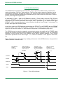
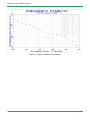
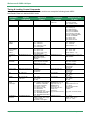
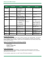
iReference+® PSRO-100 Spec
rd
Revised : 23 November 2010
Water-Proofed High-Performance GPS portable Rubidium Reference Source
PSRO-100
Smart GPS/SRO Reference Source
SmarTiming+ 1ns-Resolution Disciplining Technology Inside
®
APPLICATIONS
Kaiserin-Augusta-Allee 8 10553 Berlin Germany
3+49-30-398981-28 5+49-30-398981-39
9 [email protected] www.denk-stein.com
Military Reference/Test Source | Time/Frequency Source
©SpectraTime
Specifications are subject to change without prior notice
iReference+® PSRO-100 Spec
KEY FEATURES
GPS disciplined Rb clock
: Auto-adaptive SmarTiming+ loop time
constant, running at 1ns resolution
Power supply voltage
: DC 11.8V to 36V (standard)
Standard AC input 85- 264VAC / 47-63Hz
Reference Frequency
: Integrated GPS-locked Rubidium clock
Phase time resolution and noise
:
Output Frequency
:10MHz and 1PPS
2ps rms
Integrated smart auto calibration
Internal Bit Alarm
RS232 standard interface
: 9600 b/s
Software application
: Windows 98, XP
GPS antenna types
: Patch
External PPS synchronization input along with NMEA messages synchronization
Battery Operation Automony
Waterproof case
: up to 10 hours
:
IP 65 in accordance with DIN 40050
High temperature in accordance with MIL-STD-810 C, method 501.1
Low temperature in accordance with MIL-STD-810 C, method 502.1
Change of temperature in accordance with MIL-STD-810 C, method 503.1
©SpectraTime
Page 2 of 16
iReference+® PSRO-100 Spec
SPECIFICATIONS
ELECTRICAL
Spec
PSRO-100
Reference module
RFOUT Frequency
PPSOUT
Standard
Functionality
Short Term Stability
1s
10s
100s
Phase Noise (dBc/Hz)
(RFOUT: 10 MHz)
1Hz
10Hz
100Hz
1kHz
10kHz
Aging
(Measured after 3 months of continuous operation)
Frequency Retrace
Off/On
Options
10MHz
1PPS
See SmarTiming+ section below
(ordering code: S)
1E-11
3E-11
3E-12
1E-11
1E-12
3E-12
(ordering code: S)
-80
-75
-100
-95
-125
-145
-145
< 5E-11 / month
(typical: 3E-11 / month)
< 5E-11
24 hr / 1 hr
(In stable temperature, gravity, pressure and
magnetic field conditions)
RFOUT Levels
Spurious f0
Output
Impedance
Harmonics
100kHz (DDSOUT Off)
GPS Antenna Connector
Sine wave 0.5 Vrms ( 10% / 50
20%
50
< -25dBc
< -80dBc
)
SMA
SMARTIMING+® FUNCTIONALITY
Spec
PSRO-100
Standard
1PPS
CMOS 0-5V (+- 20 mA sink/source)
User settable, 0 to 1s in 133ns/step
< 50 ns
No GPS PPSRef noise, ± 1°C temp fluctuations
PPSOUT
Output level
Pulse width (PW) or duty cycle
PPSOUT to PPSREF Sync Error
In Sync mode
PPSOUT to PPSREF (DE)
Programmable delay (In Track mode)
PPSOUT Holdover Time Stability
Smart Loop Time Constant
Phase/Frequency
User settable
0 to 1 s in 133 ns steps
Within ± 2°C 1 ns/24 hr
Auto-adaptive 1000 to 100,000 sec
User settable Sync/Track mode **
Selected by RS232 interface
** Sync: phase/time alignment; Track: frequency alignment
GPS ANTENNA
Spec
Antenna Types
Cable Length
©SpectraTime
GPSReference
Standard
Option
Patch antenna kit
Roof antella kit (ordering
5 m / 16.4’
code RA).
Page 3 of 16
iReference+® PSRO-100 Spec
POWER
Spec
PSRO-100
Standard
Power Supply
DC 11.8V to 36V
Power Input Fluctuation
Power Consumption @25°C
10% of nominal supply voltage
< 25W after warm-up
Connector Type
Battery power autonomy at 25°C
MSxxx
> 10 hours
ENVIRONMENT
Spec
Operating Temperature ( at continuous
operation without external power supply and
at very low temperature , battery power
autonomy may decreased down to 2 hours
only TBC)
Change of temperature
Storage
Ingress protect
PSRO-100
Standard
-20°C to 50°C in accordance with MIL-STD-810C method
501.1 and 502.1
in accordance with MIL-810C, method 503.1
-25 to 60°C
IP 65 in accordance with DIN 40050
PHYSICAL
Spec
PSRO-100
Standard
Option
250x300x320 mm
9.84x11.81x12.6 in.
8.5 kg / 18.74 lbs
Size
Weight
SYSTEM SUPPLY
Type
1x
1x
1x
1x
1x
1x
1x
1x
PSRO-100
PSRO-100 box
GPS antenna
Cable Ac Power supply
Cable Dc Power supply
Cables SUB-D male/female for PC serial COM
Cables SUB-D / MIL for PC serial COM for NMEA timing messages IN/OUT
Operating manual & specifications on CD-ROM
Optional: Stable32 “Time & Frequency” software application (ordering code: ST32) on CDROM
SOFTWARE UPGRADES
PSRO-100
Download the latest software upgrades at www.spectratime.com
ORDERING INSTRUCTIONS
PSRO-100 / XX / YY / …..
Type
©SpectraTime
Option 1
Option 2
Page 4 of 16
iReference+® PSRO-100 Spec
SYSTEM DESCRIPTION
The GPSReference integrates a smart Rubidium atomic clock and a GPS receiver. It has 3 basic
modes of operation: Free Run, Track and Sync. The Free Run mode is when the Rubidium clock is
not locked to a reference, and thus free running. The Track mode is when the reference is used to
perform frequency alignment applications, whereas the Sync mode is when the reference is used to
perform phase alignment applications.
As illustrated in Figure 1, when the GPSReference works in Track mode it uses the PPS_GPS as a
reference (PPSREF) to align the frequency of the Rubidium clock. The frequency alignment is
computed by an internal phase-time error signal that is generated by an internal PPS signal
(PPSINT), which measures the signal at 1ns resolution through its SmarTiming+™ technology. The
PPSINT then aligns the PPSREF phase.
In the Sync mode, the GPSReference phase aligns the PPSOUT to the PPSREF with the PPSINT
reference signal, which uses SmarTiming+™ algorithm to 1) compare the PPSOUT and PPSREF
signals at 1ns resolution within a +/-500ns dynamic range and 2) auto-adaptively align them.
The GPSReference has also the capability to dynamically analyze the stability of the PPSREF signal
through the excellent mid-term frequency stability of the Rubidium technology. Thus, the 1PPS-GPS
reference can be directly fed to the Rubidium clock without specific analysis of the internal
optimization parameters of the GPS engine - i.e., number of satellites in view, signal to noise ratio,
etc.
Figure 2 illustrates the typical frequency stability performance of the GPSReference, using its built-in
10MHz Rubidium reference clock.
Normal initial
situation
In free-run
After track set-up,
PPSINT is aligned
within 133ns to
PPSREF
After delay ~10
PPSINT is perfectly
aligned to PPSREF
TIM
<133ns
After sync set-up,
PPSOUT is
aligned to PPSINT
TIM = 0
~0
PPSREF
PPSINT
pw
PPSOUT
/Track
/Sync
Figure 1 - Track & Sync Modes
©SpectraTime
Page 5 of 16
iReference+® PSRO-100 Spec
Figure 2 - Frequency Stability Performance
©SpectraTime
Page 6 of 16
iReference+® PSRO-100 Spec
MECANICAL DESCRIPTION
220X280X350mm Aluminium Box
©SpectraTime
Page 7 of 16
iReference+® PSRO-100 Spec
RS-232 CONTROL & MONITORING COMMANDS
Frequency Adjustments & Rb Loop Monitoring Functions
The working and monitoring parameters of the Frequency Reference module are accessible for read
and write operations through the serial RS-232 port (9600 bits/sec., no parity, 1 start bit, 8 data bits, 1
stop bit).
There are 2 basics commands as follows: M and Cxxxx
M<CR><LF>: monitors the basic internal signals of the atomic clock.
The returned answer is:
HH GG FF EE DD CC BB AA <CR> <LF>
Of which each returned byte is an ASCII coded hexadecimal value, separated by a <Space>
character. All parameters are coded at full scale.
HH:
GG:
FF:
EE:
DD:
CC:
BB:
AA:
Read-back of the user provided frequency adjustment voltage on pin 2 (0 to 5V)
reserved
peak voltage of Rb-signal (0 to 5V)
DC-Voltage of the photocell (5V to 0V)
varactor control voltage (0 to 5V)
Rb-lamp heating current (Imax to 0)
Rb-cell heating current (Imax to 0)
reserved
Cxxxx<CR><LF>:
output frequency correction through the synthesizer, by steps of 5.12 10-13 ,
where xxxx is a signed 16 bits word in hexa coded ASCII. This value is automatically stored in a
EEPROM as last frequency correction which is applied after RESET or power-ON operation.
In Track mode this correction is not in use. The function FCsddddd does the same, but the data
format is different.
There is a command to set the SYNTH output frequency:
Txxxxxxxx<CR><LF>: Where xxxxxxxx is an unsigned 32 bits in hexa coded ASCII stored in
EEPROM. The frequency is changed after a reset Frequency
©SpectraTime
xxxxxxxx
60MHz
232
Page 8 of 16
iReference+® PSRO-100 Spec
Timing & Locking Control Commands
Using the same data interface, the Reference module can accept the following basic ASCII
commands: Data is in decimal ASCII code.
Command
name
Syntax
command
Data field
(if any)
Response
syntax
Identification
ID<CR><LF>
-
TNTSRO-aaa/rr/s.ss
<CR><LF>
Serial number
Status
SN<CR><LF>
ST<CR><LF>
-
xxxxxx<CR><LF>
s<CR><LF>
Set Tracking
PPSINT PSSREF
TRx<CR><LF>
x<CR><LF>
Set
Synchronisation
PPSOUT –
PPSINT
SYx<CR><LF>
Set PPSOUT
delay
DEddddddd<CR><LF>
Set PPSOUT
Pulse Width
PWddddddd<CR><LF>
Time of day
TD<CR><LF>
x=0 : Track never
x=1 : Track now
x=2 : Track ever
x=3 : Track now + ever
x=9 : Interrogation
X=0 : Synch. never
x=1 : Synch. now
x=2 : Synch. ever
x=3 : Synch. now + ever
x=9 : Interrogation
ddddddd=delay by 133ns
step. Max 7499999
DE0000000 :synch to
PPSREF
ddddddd=pulse Width by
133ns step. Max 7499999
PW0000000: no pulse
-
Set time of day
TDhh:mm:ss<CR><LF>
Date
DT <CR><LF>
Set date
DT yyyy-mm-dd
<CR><LF>
Beat every
second
on serial port.
BTx<CR><LF>
Set frequency
adjustment
©SpectraTime
FCsddddd<CR><LF>
hh:Hours
mm:Minutes
ss:seconds
aaa: 100
rr: revision number
s.ss: software version
xxxxxx : 6 digits serial nbr
s:Status
s=0 :warming up
s=1 :tracking set-up
s=2 :track to PPSREF
s=3 :synch to PPSREF
s=4 :Free Run. Track OFF
s=5 :FR. PPSREF unstable
s=6 :FR. No PPSREF
s=7 :factory used
s=8 :factory used
s=9 :fault or Rb OOL
x:Tracking commands status
x=0 : Track OFF
x=1 : Track ON
(when Status 9 -> 4
x<CR><LF>
x:Sync. commands status
x=0 : Synch. OFF
x=1 : Synch. ON
(When Status 1 -> 2)
ddddddd<CR><LF>
ddddddd=delay by 133ns step.
Max 7499999
ddddddd<CR><LF>
ddddddd=Pulse Width by 133ns
step. Max 7499999
0000000: no pulse
hh:hours
mm:minutes
ss:seconds
hh:hours
mm:minutes
ss:seconds
yyyy : year
mm : month
dd : day
yyyy : year
mm : month
dd : day
ddddddd : delay in 133ns
step
sppp:phase error in ns
s: +/- signe
hh:hours mm:minutes
ss:secondes
s: status
hh:mm:ss<CR><LF>
hh:mm:ss<CR><LF>
yyyy-mm-dd
yyyy : year
mm : month
dd : day
x=0 : Stop beat
x=1 : Effective Time interval
PPSOUT vs PPSREF
x=2 : Phase comparator
x=3 : Both x=1 & x=2
x=4 : Beat Time of day
x=5 : Beat status
x=6 : Beat <CR><LF>
x=7 : Beat Date, Time, Status
x=A : Beat NMEA $PTNTA,
x=B : Beat NMEA $PTNTS,B,
s=+/- signe
ddddd = limited within range
: +32767/-32768
FC+99999 : interrogation
Response data
(if any)
yyyy-mm-dd
ddddddd<CR><LF> or
sppp<CR><LF> or
ddddddd sppp
<CR><LF> or
hh:mm:ss<CR><LF>
s<CR><LF>
<CR><LF>
yyyy-mm-dd hh:mm:ss s
sddddd<CR><LF>
yyyy:year, mm:month,dd:day
s: +/- signe
ddddd : frequ. Adj. in
5.12 x 10⁻¹³ step
Page 9 of 16
iReference+® PSRO-100 Spec
Command
name
Syntax
command
Set frequency
save. Integral
part, when Status
= 2, 3
FSx<CR><LF>
Set Tracking
Window
TWddd<CR><LF>
Set no Alarm
Window
AWddd<CR><LF>
Set tracking
phase loop time
constant
TCdddddd<CR><LF>
Set module
customization
MCsxx [cc…c]
<CR><LF>
Set phase
comparator
Offset
COsddd<CR><LF>
VS<CR><LF>
View PPSRef
Sigma
VT<CR><LF>
View Time
constant
Raw phase adjust RAsddd<CR><LF>
Reset micro
controller
Data field
(if any)
x=0 : never save
x=1 : save every 24 hours
x=2 : save right now
x=3 : save actual freq. now
x=9 : interrogation
ddd = Half Tracking Window
by 133ns step.
From 1 to 255
ddd = 999 : interrogation
ddd = Half no Alarm Window
by 133ns step.
From 1 to 255
ddd = 999 : interrogation
dddddd = Time constant in
seconds (001000 to 999999)
TC000000 : change to auto.
(<)TC001000 : no change
s = L : Load parameter
s = S : Store parameter ccc..c
s = B : Load start behaviour
s = A : Activate msg at start
s = C : Cancel msg at start
s = H : Load Help
s = T : Load Data Type
xx = 00..FF: msg number,
ccc…c : new welcome
message, up to 24 characters
s :+/- signe
ddd : limited with range
+ 127 / - 128
CO+999 : interrogation
Response
syntax
x<CR><LF>
x=0 : never save
x=1 : save every 24 hours
ddd<CR><LF>
ddd : Half Tracking Window
by 133ns step.
ddd<CR><LF>
ddd : Half no Alarm Window
by 133ns step.
Dddddd<CR><LF>
dddddd : time constant in
seconds
cc..c<CR><LF>
or
ccc..c : response to MCLxx
or to MCHxx.
d<CR><LF> or
xy<CR><LF>
d : 0, 1 response to MCBdd
or xy : Data Type, response
to MCTxx, x=0 RAM, x=1
eeprom, x=2 Flash, y=0 Byte,
y=1 sByte, y=2 Word, y=3
sWoord, … y=8 string ASCII,
y=9 strng binary
s :+/- signe
ddd : offset in approx
1 ns steps
sddd<CR><LF>
ddd.d<CR><LF>
dddddd<CR><LF>
s :+/- signe
ddd : limited with range
+ 127 / - 128
Response data
(if any)
sddd <CR><LF>
RESET<CR><LF>
ddd.d : Sigma of PPSRef in
ns. In tracking, Status 2, 3.
dddddd : Loop time constant
now in use, in ns.
s :+/- signe
ddd : raw phase just asked in
133 ns steps
(Identification & welcome
message, GPS binary)
Standard GPS Antenna
A GPS patch antenna with 5 meters (16.4’) of cable is included in the normal package. This antenna
can be installed close to a window. If installed in a region susceptible to lightning, a surge arrestor
must be installed. For the installation, please refer to our GPSReference user manual, section "Safe
GPS Antenna installation".
Optional Rooftop GPS Antenna (Ordering code RA)
This kit contains the following items:
- a roof antenna
- a cable of 15 meter (49’)
- a cable of 5 meter (16.4’)
- a lightning arrestor
Custom GPS Antenna
The customer can install another antenna. In such case, the antenna connector of the device
supplies 5V/30 mA for the amplifier. Please note that the device is CE tested only for an antenna
cable less than 30 meters (98’).
For the installation, please refer to our AN "Custom GPS Antenna Installation".
©SpectraTime
Page 10 of 16
iReference+® PSRO-100 Spec
NMEA system description (For synchronization NMEA input & NMEA messages
output)
RS232 speed specification: 9600 bits/sec., no parity, 8 data bits, 1 stop bit.
RS232 voltage specification
Buffer type: MAX 3311
State
Space state (0)
Mark state (1)
Transmitting
+ 4 Volt
- 4 Volt
Receiving
+ 2.4.. + 20 Volt
+ .8.. - 20 Volt
NMEA message $GPRMC
$GPRMC,hhnnss.00,a,llmm.mmmm,a,yymm.mmmm,a,,,ddmmyy,,,E*CS<CR><LF>
hhnnss.00: hour,minute,second UTC
a:
status of the clock A=ok, V= warning
llmm.mmmm: latitude in degree, minute or absent
a:
N=north S=south
yymm.mmmm: longitude in degree, minute or absent
a:
E=east W=west
Ddmmyy
day, month, year
E:
always E
CS:
check in hexa, xor of the characters between $ and *
©SpectraTime
Page 11 of 16
iReference+® PSRO-100 Spec
Electrical Bloc diagram
System I/O Interfaces
©SpectraTime
Page 12 of 16
iReference+® PSRO-100 Spec
System I/O Interfaces
TOP PLATE
N°
Type
IEC PLUG
BNC
SUB-D9-F
MIL-6P-M
SWITCH
SWITCH
SWITCH
FUSE
N°
Type
MIL-4P-F
BNC
BNC
SMA
MIL-6P-M
J5
J6
J7
J8
S1
S2
S3
F2
Definition
AC Input
1-PPS Input
Serial communication RS232
NMEA Input
On/Off switch DC
PPS or GPS Sync selection switch
On/Off switch AC
AC protection
I/O
I
I
I/O
I
-
SIDE PLATE
J1
J2
J3
J4
J9
H1
H2
H3
F1
Green/Yellow LED
Red/Green LED
Green/Yellow LED
FUSE
Definition
DC Power 10-36V
1PPS Output
10MHz Output
GPS Antenna connection
NMEA Output
Power indicator
Ready
Track
DC 10-36V protection
I/O
I
O
O
I
O
-
CONNECTORS PINOUT
N°
J1
J1
Type
MIL-4P-F
MIL-4P-F
Pin
A,B
C,D
Signal
GND
DC Power 10-36V
J7
J7
J7
SUB-D9-F
SUB-D9-F
SUB-D9-F
2
3
5
TXD
RXD
GND
J8
J8
MIL-6P-M
MIL-6P-M
A
D
(NMEA input) GND
(NMEA input) RXD
J9
J9
MIL-6P-M
MIL-6P-M
A
C
(NMEA output) GND
(NMEA output) TXD
©SpectraTime
Page 13 of 16
iReference+® PSRO-100 Spec
CABLE PINOUT
N°
J10, 20
J10, 20
Cable
Standard
Standard
Length
Type
3m
BNC
BNC
Pin
Center
Blind.
Signal
Fréquence output
GND
J30
J30
J30
Standard
Standard
Standard
3m
MIL-6P-F
MIL-6P-F
MIL-6P-F
A
C
D
GND
(NMEA output) TXD
(NMEA input) RXD
J40
J40
J40
Standard
Standard
Standard
3m
SUB-D9-F
SUB-D9-F
SUB-D9-F
2
3
5
(NMEA output) TXD
(NMEA input) RXD
GND
J50
J50
TSM
TSM
3m
SUB-D9-M
SUB-D9-M
2
5
(NMEA input, output) RXD,TXD
GND
J60
J60
Standard
Standard
3m
MIL-4P-M
MIL-4P-M
A,B
C,D
GND
DC Power 10-36V
( white )
( brown )
Cables Schematic
©SpectraTime
Page 14 of 16
iReference+® PSRO-100 Spec
# Connect
Fonction
Type 1
J1
J2
J3
J4
J5
J6
J7
J8
J9
Power supply 10.8 to 36V
PPS out
10 Mhz out
Antenna
Power Supply 230VAC
PPS in
Monitoring
Sync NMEA Intput
Sync NMEA Output
4 pin fem
BNC
BNC
SMA
2P+T
BNC
D-SUB 9P fem
6 pins male
6 pin male
H1
Power
H2
Ready
H3
Track
D
LED
Green: when ext. power applied + battery loaded
Flashing green : charging
yellow : clock ON running on battery
flashing : when battery too low
LED
Red: during warm-up or Rb failure
Green: Rb OK
LED
Green: when tracked
Flashing green : during tracking phase
Yellow: when no reference
Type 2
Fabricant
DMS 3102A14S-2S
??
??
24_SMA-50-2-14/111_N
FN284-6-06
??
DTS 9 SZ
DMS 3102A14S-6P
DMS 3102A14S-6P
DKK
??
??
Huber&Suhner
SCHURTER
??
Deltron
DKK
DKK
MARL
LED green if OK
MARL
MARL
# Switch
S1
S2
Accessories
(if room
available)
(in Box cover)
©SpectraTime
Operational/Storage (CLK OFF)
GPS / 1PPS IN
interrupteur 2 positions
interrupteur 2 positions
NKK
NKK
24V power cable (3m with mating
connector on PSRO only)
220V Standard Swiss plug cable
harness for slave clock
synchronization (3m) of TSM
Patch antenna with 6m cable
Page 15 of 16
iReference+® PSRO-100 Spec
Base in standard operation conditions
Alternative Operation Conditions (cover closed or opened)
©SpectraTime
Page 16 of 16