1
Y-1954002
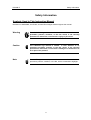
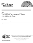
PR 4000B-F
2 Channel Power Supply and
Readout for Flow and Pressure
Instruction Manual
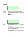
PR4000B
SETPOINT
REMOTE
CONTRAST
POWER
MKS Instruments
Deutschland GmbH
ESC
ON
ENTER
OFF
Edition 02/2008
Copyright © 2008 by MKS Instruments Deutschland GmbH
All rights reserved. No part of this work may be reproduced or transmitted in any form or by any means, electronic
or mechanical, including photocopying and recording, or by any information storage or retrieval system, except as
may be expressly permitted in writing by MKS Instruments.
Printed in the Federal Republic of Germany
PR400B-F
Table of Contents
Table of Contents
Safety Information ...............................................................................................................................9
Symbols Used in This Instruction Manual.....................................................................................9
Safety Procedures and Precautions ...........................................................................................10
Chapter 1: General Information........................................................................................................11
1.1
General Description ......................................................................................................11
1.2
Customer Support.........................................................................................................12
1.3
Intended Use.................................................................................................................12
Chapter 2: Installation ......................................................................................................................13
2.1.
Unpacking .....................................................................................................................13
2.2.
Unpacking Checklist .....................................................................................................13
2.3.
Cables...........................................................................................................................14
Interconnection Cables from MKS................................................................................14
Generic Shielded Cable Description.............................................................................15
2.4
Installation, Mounting....................................................................................................16
Rack Mounting or Table Top? ......................................................................................16
Dimensions ...................................................................................................................17
Line Power and Fuses ..................................................................................................18
2.5
Switching on the unit.....................................................................................................18
Chapter 3: Overview.........................................................................................................................19
3.1
Front Panel ...................................................................................................................19
3.2
Rear Panel ....................................................................................................................20
Connections ..................................................................................................................20
3.3
Connectors....................................................................................................................21
Channel 1 / Channel 2 ..................................................................................................21
EXTERN .......................................................................................................................21
ACCESS .......................................................................................................................22
RELAY ..........................................................................................................................22
RS232 ...........................................................................................................................23
RS485 ...........................................................................................................................23
Chapter 4: Operation.........................................................................................................................25
4.1
Structure of the Menu ...................................................................................................25
4.2
Editor.............................................................................................................................26
Switching on Edit mode ................................................................................................26
Switching off Edit mode ................................................................................................26
Decimal point ................................................................................................................26
iii
Table of Contents
4.3
PDR900
Setup............................................................................................................................ 27
Entering Setup ............................................................................................................. 27
Configuration of display 1 and display 2 ...................................................................... 28
Configuration of display 3 and display 4 ...................................................................... 28
Setpoint ........................................................................................................................ 29
Range........................................................................................................................... 29
Gain and Offset............................................................................................................ 30
Range Turndown Offset............................................................................................... 30
Input Signal Range and Output Signal Range............................................................. 31
Signalmode .................................................................................................................. 32
Linearization................................................................................................................. 34
Trip Limits..................................................................................................................... 35
Limit-Mode: .................................................................................................................. 35
Temporary Criteria ....................................................................................................... 36
Interface RS232 ........................................................................................................... 37
Interface RS485 ........................................................................................................... 37
Exit Setup..................................................................................................................... 38
4.4.
Control.......................................................................................................................... 39
Display for measurement values and setpoints........................................................... 39
Status Displays ............................................................................................................ 40
Control Display............................................................................................................. 40
Note.............................................................................................................................. 41
4.5.
Operation with pressure transducers........................................................................... 41
Operation with Baratron Type 120............................................................................... 42
Range Turndown ......................................................................................................... 42
Example for a type 120, 1 mbar full scale.................................................................... 42
4.6.
Operation with mass flow controllers (MFC)................................................................ 43
Control Modes with Mass Flow Controllers: ................................................................ 43
4.7.
Operation with flow meters .......................................................................................... 44
4.8.
Operation with pressure controllers ............................................................................. 44
4.9.
Limit switches and relays ............................................................................................. 45
SLEEP.......................................................................................................................... 45
LIMIT ............................................................................................................................ 45
BAND ........................................................................................................................... 45
MLIMIT ......................................................................................................................... 45
MBAND ........................................................................................................................ 45
4.10.
Relay Settings .............................................................................................................. 46
Chapter 5: Interface.......................................................................................................................... 47
5.1.
General ........................................................................................................................ 47
5.2.
Command syntax ......................................................................................................... 47
iv
PR400B-F
Table of Contents
5.3.
Reply syntax .................................................................................................................48
5.4.
Error reply syntax..........................................................................................................48
5.5 Commands ............................................................................................................................49
Sample Command ........................................................................................................49
Display Text (DT) ..........................................................................................................49
Request Key (KY) .........................................................................................................49
Dialog (DG) ...................................................................................................................50
ID String (ID) .................................................................................................................50
Remote Mode (RT) .......................................................................................................50
Access Channel (AC) ...................................................................................................50
Actual Value (AV)..........................................................................................................51
Setpoint (SP).................................................................................................................51
External Input (EX)........................................................................................................51
Status (ST)....................................................................................................................51
Valves (VL) ...................................................................................................................52
Relays (RL) ...................................................................................................................52
Displays (DP) ................................................................................................................52
Display 4 (DP4).............................................................................................................52
Range (RG)...................................................................................................................53
Gain (GN)......................................................................................................................53
Offset (OF) ....................................................................................................................53
RTD Offset (RO) ...........................................................................................................53
Autozero (AZ)................................................................................................................54
Input Range (IN) ...........................................................................................................54
Output Range (OT) .......................................................................................................54
External Input Range (EI) .............................................................................................54
External Output Range (EO).........................................................................................54
Signal Mode (SM) .........................................................................................................55
Scale (SC).....................................................................................................................55
Linearization (LN, LS) ...................................................................................................55
Limit Mode (LM) ............................................................................................................55
Dead Band (DB) ...........................................................................................................56
Upper Limit (UL) ...........................................................................................................56
Lower Limit (LL) ............................................................................................................56
Formula Relay (FR) ......................................................................................................56
Formula Temporary (FT) ..............................................................................................57
Parity (PY).....................................................................................................................57
Baudrate (BD) ...............................................................................................................57
Address (AD) ................................................................................................................57
Interface Mode (IM) ......................................................................................................57
v
Table of Contents
PDR900
Resolution (RS)............................................................................................................ 58
Reset Status (RE) ........................................................................................................ 58
Default (DF) ................................................................................................................. 58
Unlock (#0)................................................................................................................... 58
Lock (#1) ...................................................................................................................... 58
Tweak Control ($0, $1, ?$) .......................................................................................... 58
Appendix A: Specifications.............................................................................................................. 59
Appendix B: Error Messages........................................................................................................... 61
Appendix C: Default – Configuration ............................................................................................... 63
Appendix D: Dialog Reference ........................................................................................................ 65
MKS Worldwide Calibration & Service Centers ............................................................................... 67
vi
PR400B-F
Table of Contents
List of Figures
Figure 1: Rack angles assembly ......................................................................................................16
Figure 2: Rubber feet assmbly .........................................................................................................16
Figure 3: Dimensions .......................................................................................................................17
Figure 4: Front Panel........................................................................................................................19
Figure 5: Rear Panel ........................................................................................................................20
Figure 6: Structure of the menu .......................................................................................................25
List of Tables
Table 1: Standard Interconnecting Cables.......................................................................................15
Table 2: Fuse Information ................................................................................................................18
vii
Table of Contents
PDR900
This page left blank.
viii
PR400B-F
Safety Information
Safety Information
Symbols Used in This Instruction Manual
Definitions of WARNING, CAUTION, and NOTE messages used throughout the manual.
Warning
The WARNING sign denotes a hazard. It calls attention to a
procedure, practice, condition, or the like, which, if not correctly
performed or adhered to, could result in injury to personnel.
Caution
The CAUTION sign denotes a hazard. It calls attention to an
operating procedure, practice, or the like, which, if not correctly
performed or adhered to, could result in damage to or destruction of
all or part of the product.
Note
The NOTE sign denotes important information. It calls attention to a
procedure, practice, condition, or the like, which is essential to highlight.
9
Safety Information
PR400B-F
Safety Procedures and Precautions
The following general safety precautions must be observed during all phases of operation of
this instrument. Failure to comply with these precautions or with specific warnings elsewhere in
this manual violates safety standards of intended use of the instrument and may impair the
protection provided by the equipment. MKS Instruments assumes no liability for the customer’s
failure to comply with these requirements.
DO NOT SUBSTITUTE PARTS OR MODIFY INSTRUMENT
Do not install substitute parts or perform any unauthorized modification to the instrument. Return
the instrument to an MKS Calibration and Service Center for service and repair to ensure that all
safety features are maintained.
SERVICE BY QUALIFIED PERSONNEL ONLY
Operating personnel must not remove instrument covers. Component replacement and internal
adjustments must be made by qualified service personnel only.
GROUND THE PRODUCT AND USE PROPER ELECTRICAL FITTINGS
Dangerous voltages are contained within this instrument. All electrical fittings and cables must be
of the type specified, and in good condition. All electrical fittings must be properly connected and
grounded.
This product is grounded through the grounding conductor of the power cord. To avoid electrical
shock, plug the power cord into a properly wired receptacle before connecting it to the product
input or output terminals. A protective ground connection by way of the grounding conductor in the
power cord is essential for safe operation.
DANGER ARISING FROM LOSS OF GROUND
Upon loss of the protective-ground connection, all accessible conductive parts (including knobs
and controls that may appear to be insulating) can render an electrical shock.
USE THE PROPER POWER CORD
Use only a power cord that is in good condition and which meets the input power requirements
specified in the manual.
Use only a detachable cord set with conductors that have a cross-sectional area equal to or
greater than 0.75 mm2. The power cable should be approved by a qualified agency such as VDE,
Semko, or SEV.
10
PR400B-F
Chapter 1: General Information
Chapter 1: General Information
1.1
General Description
The control unit PR4000B is designed for the use with mass flow controllers (MFC), mass flow
meters (MFM), pressure transducers and in-line-pressure controllers, e.g. type 640 from MKS
Instruments. Compatibility is just restricted in case of disagreement of electrical specifications.
The PR4000B is available as single or dual channel power supply, readout and control unit. This
instruction manual however describes only the dual channel version PR4000B-F (single channel
version: PR4000B-S). Two or more units PR4000B can be combined thus performing multichannel
control units.
Further features:
•
Display with four or five digits, selectable
•
2 trip limits and 2 relays, can be combined and configured in a wide variety of functions and
combinations
•
linearization possible for both channels
•
Interface either RS232 (standard) or RS485 (optional)
•
2 different power supplies: ±15 V / 1,5 A or 24 V / 1 A
•
two line display, configurable, allows simultanous readout of both channels or one channel
actual value plus setpoint
•
physical values displayed with engineering units
•
non volatile memory for easy restart after power loss or switching off power
For more details and specifications refer to Appendix A, Specifications
11
Chapter 1: General Information
1.2
PR400B-F
Customer Support
Standard maintenance and repair services are available at all of our regional MKS Calibration and
Service Centers, listed on the last page. In addition, MKS accepts the instruments of other
manufacturers for recalibration using the Primary and Transfer Standard calibration equipment
located at all of our regional service centers. Should any difficulties arise in the use of your
PR4000B-F, or to obtain information about companion products MKS offers, contact any
authorized MKS Calibration and Service Center. If it is necessary to return the instrument to MKS,
your service center can inform you about the need for an ERA Number (Equipment Return
Authorization Number) or a form for declaration of decontamination or any other regulations before
shipping. The ERA Number expedites handling and ensures proper servicing of your instrument.
Please refer to the last page of this manual for a list of MKS Calibration and Service Centers.
Warning
1.3
All returns to MKS Instruments must be free of harmful, corrosive,
radioactive, or toxic materials.
Intended Use
The PR4000B is a power supply and readout unit for operation of MKS mass flow meters, mass
flow controllers, pressure transducers and in-line pressure controllers. Combination with units of
other manufacturers may be possible given operating specifications that match MKS hardware
requirements. However, MKS Instruments does not guarantee any warranty for these system
configurations, and will not be liable for any consequential or incidental damages occurring through
these combinations.
12
PR400B-F
Chapter 2: Installation
Chapter 2: Installation
2.1. Unpacking
MKS has carefully packed the Type PR4000B unit so that it will reach you in perfect operating
order. Upon receiving the unit, however, you should check for defects, cracks, broken connectors,
etc., to be certain that damage has not occurred during shipment.
Note
Do not discard any packing materials until you have completed your
inspection and are sure the unit arrived safely.
If you find any damage, notify your carrier and MKS immediately. Please refer to the last page of
this manual for a list of MKS calibration and service centers.
Caution
Only qualified individuals should perform the installation and any
user adjustments. They must comply with all the necessary ESD
and handling precautions while installing and adjusting the
instrument. Proper handling is essential when working with all
highly sensitive precision electronic instruments.
2.2. Unpacking Checklist
Standard Equipment:
•
PR4000B-F power supply & readout unit
•
4 rubber feet for tabletop use
•
Power cable
•
Mating connector kit
•
Instruction manual (this book)
Optional:
•
Connection cable(s), e.g. for transducers, controllers etc.
13
Chapter 2: Installation
PR400B-F
2.3. Cables
The unit complies with the European standards
•
EN50011:1991:
Interference Emmisions
(Group 1, Class B)
•
EN50082-2:1995:
Immunity from Noise
ESD according to IEC801-2:1991
EMF according to ENV50140:1993 resp. 50204:1995
Burst according to IEC801-4:1988
Line Noise according to ENV50141:1993
•
EN61010-1:1993:
Device Safety
and thus it is labelled with the CE-mark. To fullfill the above listed guidelines it is mandatory to use
the approbriate interconnection cables.
Note
An overall metal braided shielded cable, properly grounded at both ends,
is required to meet CE specifications.
We recommend to use the cables offered by MKS Instruments.
Cables which are in compliance with the CE guidelines are marked with
an „E“ or „S“ (example: CB259E-... or CB259S-...).
Interconnection Cables from MKS
The following table lists the standard cables provided by MKS Instruments. They are all in
compliance with the CE guidelines. If the cable needed for your particular instruments is not listed
there then please contact your MKS center.
The cable length is 3 meters (standard length), 5 m or 10 m (optional).
For cable length greater than 10 m please contact your MKS center.
(continued on next page)
14
PR400B-F
Chapter 2: Installation
Cables for combination with the PR4000
For pressure transducers or in-line pressure controllers
type or series
MKS-Cable Type
120
CBE 120-96-3M
121
CBE 112-14-3M
622, 623, 624, 625, 223, 122A
CBE 112-2-3M
621, 626, 627, 628, 127, 128,722A (with 15-pin type D connector)
CBE 259-5-3M
722 (9-pin type D connector)
CBE 700-1-3M
722 (terminal block)
CBE 700-99-3M
For mass flow meters (MFM) or mass flow controllers (MFC)
mit 15-pin type D connector:
179, 1179,2179,1479, 1259, 2259, 258, 358, 1359, 558, 1559, M100
CBE 259-5-3M
mit 9-pin type D connector:
CBE147-12-3M
1179, 2179, 1479, M200, M330
Table 1: Standard Interconnecting Cables
Note
Flow controllers with 9-pin connector do not have the „Valve Close“ input
(remotely closing of the control valve).
Generic Shielded Cable Description
MKS offers a full line of cables for all MKS equipment. Should you choose to manufacture your
own cables, follow the guidelines listed below:
1.
The cable must have a braided shield, covering all wires. Neither aluminum foil nor spiral
shielding will be as effective; using either may nullify regulatory compliance.
2.
The connectors must have a metal case which has direct contact to the cable’s shield on the
whole circumference of the cable. The inductance of a flying lead or wire from the shield to the
connector will seriously degrade the shield’s effectiveness. The shield should be grounded to
the connector before its internal wires exit.
3.
With very few exceptions, the connector(s) must make good contact to the device’s case
(ground). “Good contact” is about 0.01 ohms; and the ground should surround all wires.
Contact to ground at just one point may not suffice.
4.
For shielded cables with flying leads at one end; it is important at such end, to ground the
shield before the wires exit. Make this ground with absolute minimum length. After picking up
the braid’s ground, keep wires and braid flat against the case. With very few exceptions,
grounded metal covers are not required over terminal strips. If one is required, it will be stated
in the Declaration of Conformity or in the instruction manual.
15
Chapter 2: Installation
5.
PR400B-F
In selecting the appropriate type and wire size for cables, consider:
a.
The voltage ratings;
b.
The cumulative I2R heating of all the conductors (keep them safely cool);
c.
The IR drop of the conductors, so that adequate power or signal voltage gets to the
device;
d.
The capacitance and inductance of cables which are handling fast signals, (such as data
lines or stepper motor drive cables); and
e.
That some cables may need internal shielding from specific wires to others; please see
the instruction manual for details regarding this matter.
2.4
Installation, Mounting
The PR4000B-F is designed for use in dry and warm environment with sufficient ventilation. The
device must be installed in such a way that air can circulate free. Do not cover the openings at the
instrument’s housing. If there are heat loss generating devices located next to the unit make sure
that no excessive heat is transferred to the unit.
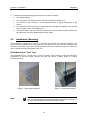
Rack Mounting or Table Top?
The PR4000B fits to a 19“ half rack or on top of a table. Three screws on each side allow dis-/
assembling of the rack angles. Rubber feet give the device a stable stand on a table.
(Screws are TX10)
Figure 1: Rack angles assembly
Note
Figure 2: Rubber feet assmbly
Position the unit with proper clearance to allow air cooling, so that the
unit can operate within the specified temperature as listed in appendix A.
Do not cover the openings at the instrument’s housing.
16
PR400B-F
Chapter 2: Installation
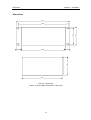
Dimensions
241
203,3
18,85
86
18,85
185
Figure 3: Dimensions
(above: Front and Rear Panel; below: Side View)
17
88
76,2
226
Chapter 2: Installation
PR400B-F
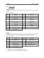
Line Power and Fuses
Line cord plug, the holder for the line fuse and the fuses of the power supply output are located at
the rear panel (see figure 4).
Refer to the following table in case that the line fuses must be changed or replaced
Fuse
Type
Line
1,25 A Slow Blow
Process Power F1, F2
Wickmann (Little Fuse), No.372 / TR5, 1.6Amp
Table 2: Fuse Information
Use only fuses as specified in table 2. Before replacing any fuse the failure that caused the blow
must be identified and eliminated. Do not open the housing! In any case of trouble switch the unit
off and disconnect the line power cable from the PR4000B. Do not perform any internal repair but
contact MKS for service.
To replace the line fuse lift the fuse holder using a srewdriver with small blade. There is a spare
fuse placed in the holder. The power output fuses F1 and F2 are being replaced by pulling them off
the rear panel (tightly grabbing with two fingers).
Caution
Separate the instrument completely from mains before replacing
any fuse!
Make sure the fuse type applies to the specifications given in this
manual.
Protective Grounding
Connect the power cord PR4000B only to a properly grounded outlet.
2.5
Switching on the unit
After all connections to the peripheral instruments, e.g. pressure transducer, mass flow controller
etc. are properly done the unit can be switched on. Refer to the instructions for the peripheral units
for proper installation, connection, set up and warm up.
The elements on the front and rear panel and their functions are explained in the following chapter.
18
PR400B-F
Chapter 3: Overview
Chapter 3: Overview
3.1
Front Panel
LED for set-point
Display
LED for remote
operation
PR4000B
SETPOINT
REMOTE
CONTRAST
POWER
Power switch
Escape key
ESC
ON
ENTER
OFF
Enter key
Arrow keys for
dialog selection
Screw for
contrast
On/off switch
for set-point
Figure 4: Front Panel
Display:
Two lines. Each line 16 characters. Simultaneous readout for both channels
possible.
POWER
Button switch toggles between standby and operation. For total breakup from
mains use switch on the rear side. The LED above indicates the device in
operation.
ENTER
Accepts and stores entered data.
ESC (Escape)
Switches stepwis back finally to display #1 mode.
Arrow buttons
Navigation in the menues
ON , OFF
Switches the setpoint output. Note: Channel valve switch (channel preselection)
must be activated for setpoint output.
SETPOINT
LED, lit when setpoint output active.
REMOTE
LED, lit when unit is operated through serial interface.
CONTRAST
Allows adjustment of display contrast.
19
Chapter 3: Overview
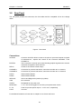
3.2
PR400B-F
Rear Panel
The rear panel provides all connectors, the fuse holder and the receptable for the line voltage
cable.
MAIN PWR
RS232
ACCESS
CHANNEL2
RS485
EXTERN
CHANNEL1
RS485
I
O
F1
RELAY
SERVICE
FUSE
USB
F2
LINE IN
Figure 5: Rear Panel
Connections
ACCESS
Connector ACCESS. Direct access to the pins for inputs and outputs of signals
of measurement , setpoint and controls of the connectors CHANNEL 1 and
CHANNEL 2.
EXTERN
This connection is used to input external analog setpoint signals and to monitor
measurement signals of both channels.
RELAY
Access to the contacts of both relays.
CHANNEL 1
Connection for pressure transducer, mass flow controller etc. to channel 1
CHANNEL 2
Connection for pressure transducer, mass flow controller etc. to channel 2
RS232
Serial Interface RS232
RS485
Serial Interface RS485
SERVICE
Service and Diagnostics (used only by MKS)
USB
No connection
LINE IN
Receptable for line power cord
MAIN PWR
I = On; unit can be toggled on and off by front panel button switch
F1, F2
Fuses for process power output ± 15 V or 24 V, respectively
FUSE
Line fuse
For detailed informations to fuses refer to chapter 2 Line Power and Fuses.
20
PR400B-F
3.3
Chapter 3: Overview
Connectors
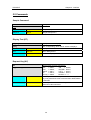
Channel 1 / Channel 2
These connectors serve to connect pressure transducers, flow meters, flow or pressure controllers
to the unit.
15-pin., Sub-D, Socket
Pin
Function
Pin
Function
1
reserved
9
reserved
2
Signal Input
10
reserved
3
Flow controllers: Valve Close
11
Signal ground
Baratron type 120: Range Turndown
for pin 2 and pin 8
4
Valve Override
12
same as pin 11
5
± 15 V Ground
13
reserved
6
- 15 V
14
reserved
7
+ 15 V
15
Chassis ground
8
Setpoint output
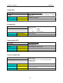
EXTERN
This connector is preferable used to monitor the flow or pressure signal of the device connected to
the respective channel and / or to feed an external setpoint voltage into the instrument.
9-pin., Sub-D, Socket
Pin
Function
Pin
Function
1
External setpoint to CH 1
6
Signal input CH 1*
2
External setpoint to CH 2
7
Signal input CH 2*
3
Signal output CH 1
8
Signal ground for pin 6**
4
Signal output CH 2
9
Signal ground for pin 7**
5
± 15 V Ground
*)
Identical to Pin 2 of the corresponding channel connector
**)
Identical to pin 11&12 of the corresponding channel connector
21
Chapter 3: Overview
PR400B-F
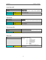
ACCESS
This connector provides access to different utility signals on the channel connectors, without the
need of making a split cable. The access is a direct one, that means there is no electronic circuitry
between and it may also be used for troubleshooting or override the control valve of a mass flow
controller or in-line pressure controller.
9-pin. Sub-D, Socket
Pin
Function
Pin
Function
1
Channel 1, Pin 1
6
Channel 2, Pin 1
2
Channel 1, Pin 4
7
Channel 2, Pin 4
3
Channel 1, Pin 9
8
Channel 2, Pin 9
4
reserved
9
reserved
5
± 15 V Ground
RELAY
15-pin:; Sub-D, Socket
Pin
Function
Pin
Function
1
Relay 1, Normally closed
9
Relay 1, Common
2
Relay 1, Normally open
10
Relay 2, Normally closed
3
Relay 2, Common
11
Relay 2, Normally open
4
reserved
12
reserved
5
reserved
13
reserved
6
reserved
14
reserved
7
reserved
15
reserved
8
+15 V Ground
22
PR400B-F
Chapter 3: Overview
RS232
9-pin., Sub-D, Pin
Pin
Function
Pin
Function
1
No connection
6
No connection
2
RXD
7
No connection
3
TXD
8
No connection
4
No connection
9
No connection
5
GND
RS485
15-pin., Sub-D
Pin
Function
Pin
Function
1
Shield
9
Send Data T (B)
2
Send Data T (A)
10
No connection
3
No connection
11
Receive Data R (B)
4
Receive Data R (A)
12
No connection
5
No connection
13
No connection
6
No connection
14
U2 = +15 V/24 V (optional)
7
GND 2
15
U1 = +5 V (optional)
8
GND 2
23
Chapter 3: Overview
PR400B-F
This page left blank.
24
PR400B-F
Chapter 4: Operation
Chapter 4: Operation
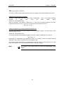
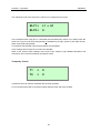
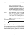
After switching on the power the following information is displayed for 2-3 seconds:
PR4000
2CHANNELS
V 2.02
Oct30,07
(here: Version 01.29 ; Oct. 11, 1999)
Then the unit switches automatically to display 1, which may be used for routine operation. This
section describes how to configurate the different displays and how to set the parameters for
operation and control.
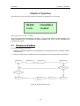
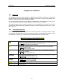
4.1
Structure of the Menu
The menu is divided in two levels:
1. Displays for standard operation. These displays show measurement values, setpoints, trip limit
information etc.
2. Setup. Here the system configuration and the displays are set and parameters can be edited.
Display1
Display2
Display3
Display(n)
Operation Level
ENTER?
EXIT?
Param.(n)
Param.3
Param.2
Setup-Level
Figure 6: Structure of the menu
25
Param.1
Chapter 4: Operation
PR400B-F
It is recommended to deactivate the entry into the setup (see figure 4) after all parameters have
been edited. This allows quick switching through the 1 to 4 operational displays in a circular mode
without stepping through all setup dialogs.
By pressing the escape key (ESC) one time it is easily possible to switch the unit back to the
display #1 from any position in any level.
4.2
Editor
The PR4000B-F is operated and configured by dialogs (two-line LCD) or digital I/O
(RS232/RS485). The dialogs are organized in a simple table hierarchy. All the dialogs can be
accessed and displayed easily: you can change from one dialog to another using the up/down
arrow keys or return to the main dialog at any time by pressing the ESC key. The dialog table is
divided in two parts, an operation and a setup part.
Switching on Edit mode
Edit mode can be switched on or off in the dialogs. You can enter numeric values in Edit mode,
alter variables, etc. There are two ways of switching on Edit mode:
1. With the ENTER key
2. With the left/right arrow keys
or
3. When you switch on Edit mode, the cursor appears as a flashing underscore below the first or
last alphanumeric character. You can move the cursor within a line using the left/right arrow
keys or change the preset values with the up/down arrow keys.
If '9' is displayed and you press the up/down arrow keys again to scroll the number, the display
automatically creates two digits ('10'); the same applies analogously in the opposite direction.
If, when you exit Edit mode by pressing the ENTER key, the value you have set is outside the valid
range, the highest or lowest permitted value is stored instead.
Switching off Edit mode
You can switch off Edit mode again by pressing the ENTER key. The entered values are not stored
until you press the ENTER key.
You can also exit Edit mode with the ESC key. In this case, however, the values are not stored.
Decimal point
You can mark the decimal point in this dialog with the left/right arrow keys and shift it with the
up/down keys. The up arrow shifts the cursor to the left, while the down arrow shifts it to the right.
The new decimal point setting takes effect in all the dialogs in which measured values or values
directly referred to them are displayed. It does not affect device parameters, such as Gain.
26
PR400B-F
4.3
Chapter 4: Operation
Setup
It is recommended to check all parameters for correct settings before starting operation. Detailed
information for operation of the different kind of transducers, controllers etc. are given later in this
chapter. For understanding these instructions it is necessary to have studied the setup
informations before.
After switching on the power or pressing the escape key (ESC) you will see the first display
configured for operation (typically display #1). By consecutively pressing the down arrow key you
will come to the operation / setup level junction.
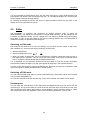
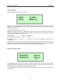
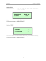
Entering Setup
SETUP
RESET
Enter the setup submenu by pressing the right arrow key. A cursor appears under the word
SETUP. Confirm by pressing the enter key (ENTER). Or simply press two times the enter key!
For deactivating the setup level refer to Exit Setup later in this chapter.
If you mark the word RESET with the cursor and confirm with RESET then all parameters are set
to their default values.
Remember that you leave with they ESC key without changing anything in the particular window.
Note
Access to the setup submenu can be locked and unlocked by applying
respective commands via the serial interface communication port. The
commands are described in section 5.5.
Note
By using the default settings you can ease the setup procedure. Refer to
Exit Setup (last window of the setup level) of how select either pressure
or flow setup.
Once entered the setup submenu use the down/up arrow keys to step successively to the different
windows.
27
Chapter 4: Operation
PR400B-F
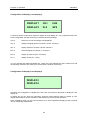
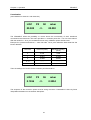
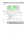
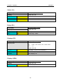
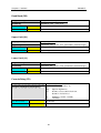
Configuration of display 1 and display 2
DISPLAY1
CH1
CH2
DISPLAY2
FL2
SP2
In this first window of the setup submenu display #1 and display #2 of the operational level are
being configurated. Use the arrow keys to select and set the settings:
CH1,2
select one or both channel(s) to be displayed
VA1,2
display the signal output of channel 1 and/or channel 2
SP1,2
display setpoint of channel 1 and/or channel 2
EX1,2
external setpoint for channel 1 / channel 2
PR1,2
display as pressure (PR = Pressure)
FL1,2
display as flow (FL = Flow)
You can activate and deactivate display #2: Place the cursor between the word DISPLAY2 and
the following character, then make your choice with the up/down arrow keys.
Configuration of display 3 and display 4
DISPLAY3
DISPLAY4
Activation and configuration of display #3 is done the same way as described for display #1 and
display #2.
In display #4 you can write any information using the serial interface (refer to chapter 5). The
display itself however can be activated or deactivated only via front panel operation.
After completing setup you may have therefore up to three operational displays whose contents
can be individually configurated.
28
PR400B-F
Chapter 4: Operation
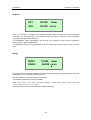
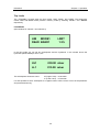
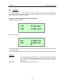
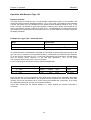
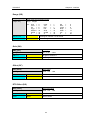
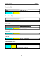
Setpoint
SP1
05.000
mbar
SP2
20.000 sccm
Here you can enter the setpoint for massflowcontrollers (MFC) as well as for in-line pressure
controllers, e.g. MKS type 640. The example shows an MFC on channel 2 and a pressure
controller being operated by channel 1.
The PR4000B-F takes automatically into account any corrections which may be necessary
because of zero offset compensation.
The adjustable range and the engineering units are determined by the choosen range as shown
next:
Range
RNG1
10.000
mbar
RNG2
50.000 sccm
Place the cursor by using the left/right arrow keys under the parameter to be edited. Edit range and
engineering unit by using the up/down arrow key.
Also the position of the decimal point can be edited.
The following engineering units are available:
mbar – bar – mTorr – Torr – kTorr – Pa – kPa – mH2O – cmH2O – PSI – N/m2 – sccm – slm – scm
– scfh – scfm – mA – V - % - C – μbar.
All ranges may be set in a format between 99999 und 00000.
29
Chapter 4: Operation
PR400B-F
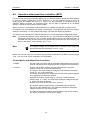
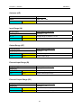
Gain and Offset
(extra windows for channel 1 and channel 2)
GAIN1
01.0000
OFFS1
- 00043 mV
GAIN is a factor which adapts the range and the measurement signal for correct readout. A typical
application is to use the gain factor as the gas correction factor with thermal mass flow meters or
mass flow controllers.
Available range setting: 0.001 – 2.000.
Example for a MFC at channel 1, calibrated for 200 sccm full scale of nitrogen. The process gas
used is carbon dioxide CO2. The gas correction table in the user manual of the mass flow controller
indicates a gas correction factor of 0.70 .
Range setting:
RNG1
200.00 sccm
Gas correction factor setting:
GAIN
00.7000
This finally results in a range of
PR4000B-F.
0 – 140 sccm CO2, which is displayed correctly by the
OFFS is the zero offset value of the respective input signal. Typically the zero offset is corrected by
the auto zero cycle (refer to section Control) and the resulting value is shown here. It also possible
to enter the respective value here which may be necessary in exceptional cases.
Range Turndown Offset
RTDOFFS1
-005 mV
RTDOFFS2
000 mV
The PR4000B-F allows the user to switch a Baratron 120 series in the range turndown mode
automatically. This is described in detail in the section Control. The auto zero mode determines the
zero offset value of both ranges to achieve highest accuracy.
It is of course also possible to enter the offset values for both ranges manually as described in the
menu before.
30
PR400B-F
Chapter 4: Operation
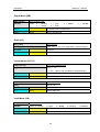
Input Signal Range and Output Signal Range
(extra windows for channel 1 and channel 2)
IN1
10V
EI1
5V
OUT1 5V
EO1
5V
Each signal input and output can be set for a range between 1 V and 10 V in steps of 1 V. This
allows the use of MFC’s with 10 V full scale flow and/or 10 V setpoint signal or pressure
transducers with for example 5 Volt full scale.
Select with the left/right arrow keys the respective parameter and make the setting using the
up/down arrow keys.
IN1
Signal full scale of the transducer or controller connected to channel 1
(Pin 2, connector CHANNEL 1)
OUT1
Setpoint signal full scale for the MFC or pressure controller connected to
channel 1 (Pin 8, connector CHANNEL 1)
EI1
External setpoint input for channel 1 (Pin 1, connector EXTERN)
EO1
Monitor signal output of channel 1 (Pin 3, connector EXTERN)
Respectively for channel 2 :
IN2
Signal full scale of the transducer or controller connected to channel 2
(Pin 2, connector CHANNEL 2)
OUT2
Setpoint signal full scale for the MFC or pressure controller connected to
channel 2 (Pin 8, connector CHANNEL 2)
EI2
External setpoint input for channel 2 (Pin 2, connector EXTERN)
EO2
Monitor signal output of channel 2 (Pin 4, connector EXTERN)
Confirm all settings with the ENTER key bevor you leave the window.
31
Chapter 4: Operation
PR400B-F
Signalmode
(extra window for channel 1 and channel 2)
SIGMODE1
SCL1
INDEP
10.000 mbar
SIGMODE:
For controllers the parameter SIGMODE determines the source of the setpoint which shall be
applied the the respective channel. For meters this parameter determines to which value the
setpoint output is set.
INDEP
(Independent) Setpoint is set either by the front panel settings or
by remote host computer. Manual setpoint adjust can be done
either in the setup submenu or in a window in the operational level
(if the window is configured for displaying setpoint).
OFF
Setpoint output voltage is set to a fixed voltage of about – 0,5 V .
This ensures that the integrator of a controller connected to this
channel does not wind up thus opening the control valve
unintendendly. The digital output connector CHANNEL1 or
CHANNEL2, pin 4 is held to LOW. This activates the input Valve
Close of MFC’s, forcing the control valve to be closed.
METER
Setpoint output voltage is set to zero volts. Valve override line via
pin 4 of the respective channel connector is set to HIGH.
RTD
Range-Turndown (RTD) allows operation of a Baratron type 120.
The digital output pin 4 of connector CHANNEL1 or CHANNEL2 is
set to LOW when the signal of the type 120 is falls below 1 V. This
enables the PR4000B-F to display also the lower pressure
decades in full reolution.
Refer to section CONTROL detailed instructions.
SLAVE
The setpoint of a slave channel is derived from the other channel’s
signal. This allows the control of gas mixing systems with a fixed
flow ratio.
EXTRN (external setpoint)
The channel’s setpoint is derived by an external analog voltage
source, connected to connector EXTERN.
32
PR400B-F
Chapter 4: Operation
SCL (only SLAVE or EXTRN ) :
The value of SCL (Scaler) determines the ratio of the setpoint which will be applied to the slave.
Example for two mass flow controllers:
Channel 1: MFC 500 sccm full scale, Mode Independent.
Channel
2:
MFC
200
sccm
full
Scaler SCL set to 080.00 sccm.
This is the master channel!
scale,
Mode
Slave.
When the master’s flow readout ranges from 0 –500 sccm the setpoint applied to the slave
ranges proportionally from 0 – 80 sccm ! The gas mixing ratio therefore is set to:
500 : 80 = 6,25 : 1
Example as before but for external setpoint mode EXTRN:
Channel 1: MFC 500 sccm full scale, Mode EXTRN (this makes channel 1 to be the „slave“ of the
external setpoint source!
Scaler SCL set to 350.00 sccm.
This means that the external setpoint applied to channel 1 will be scaled down by a factor of
350 : 500 = 0,7.
Depending on configuration and operational mode it is possible to have the setpoint input(s)
displayed. This however is possible only in the INDEP mode.
For optimum control performance it is advised not to set the scaler to values below 20 % off the
MFC. It is possible but you should instead use MFC’s with lower ranges.
Note
The setting of the scaler does not affect the independence mode
INDEP !
33
Chapter 4: Operation
PR400B-F
Linearization
(extra window for channel 1 and channel 2)
LIN1
P0
00.000
S0
<>
mbar
00.000
The PR4000B-F offers the possibility to correct known the non-linearity of each transducer
connected to the instrument. This menu provides 11 correction points P0 – P10 for each channel.
With the values S0 – S 10 you can determine how many calibration points shall be used.
Example for a pressure transducer, 1 mbar full scale. The 6 point calibration data sheet lists the
known deviation:
Cal. Point
Pressure (mbar)
Baratron Reading
(mbar)
0
0,000
0,000
1
0,1051
0,1048
2
0,1996
0,2004
3....5
........
.........
6
1,0137
1,0121
Then the settings for P and S for the correction point #2 would be:
LIN1
0.1996
P2
S6
<>
mbar
0.2004
The sequence of the correction points must be strong monotone. Linearization is done by linear
interpolation between two consecutive data points.
34
PR400B-F
Chapter 4: Operation
Trip Limits
The PR4000B-F provides three trip limit modes: LIMIT, BAND and SLEEP. The supervision
modes LIMIT and BAND further provide a memory mode by selecting MLIMIT and MBAND
respectively.
Limit-Mode:
(extra window for channel 1 and channel 2)
LIM
MODE1
LIMIT
DEAD BAND1
1.5%
In the limit mode you can set two switchpoints and the hysteresis. In the window shown the
hysteresis (DEAD BAND) is set to 1,5%.
UL1
030.00 mbar
LL1
015.00 mbar
The switchpoints shown are set to:
UL (Upper Limit) = 30,00 mbar
LL (Lower Limit) = 15,00 mbar
It is also possible to set a switchpoint to a negative value: Set the cursor in front of the parameter
and press the down key.
35
Chapter 4: Operation
PR400B-F
The switching mode of the relay RLY1 and RLY2 is configured in this menu:
RLY1 =
L1 v U1
RLY2 =
0
In the example shown relay RLY1 is activated (and simultaneously shown is it‘s status) when the
lower limit 1 (here 15,00 mbar) was passed or (indicated by the logic symbol V) the upper limit U1
(here 30,00 mbar) was passed.
To both limits the selected value for the hysteres must be added.
In the example shown relay RLY2 is set to an idle state.
Refer to the section Relay Settings at the end of this chapter to get detailed description and
instructions of the numerous settings and logical criteria.
Temporary Criteria
T1
=
0
T2
=
0
Transient events can also be combined with the relay operation.
For more instructions refer to the section Relay Settings at the end of this chapter.
36
PR400B-F
Chapter 4: Operation
Interface RS232
Selectable baud rates:
110 – 1200 – 2400 – 4800 – 9600 – 19200 – 38400 –57600 –
76800 – 115000 Baud
BAUDRATE
9600 Bd
PARITY
Parities:
ODD
Odd – Even – None
For more instructions refer to chapter 5 INTERFACE.
Interface RS485
ADRESS
--
IFACEMODE
--
In this menu the adress and interface mode are selected (Only for units with RS485 interface)
For more instructions refer to chapter 5 INTERFACE.
37
Chapter 4: Operation
PR400B-F
Exit Setup
RESET
DEFAULT F
RESOL16
♦
EXIT
RESET
All error messages will be reset.
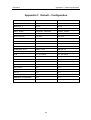
DEFAULT F
Setup menu will completely set to standard settings for MFC’s and MFM
DEFAULT P
Setup menu will completely set to standard settings for Baratron pressure
transducers.
In appendix B you will find a complete table showing the default settings for both
flow and pressure.
RESOL16
activated (indicated by a diamond shaped sign):
4,5 digit display format,
recommended for pressure measurement with Baratron pressure
transducers.
De-activated (no diamond sign):
3,5 digit display format,
preferable for flow measuremnt and control with thermal flow
devices.
EXIT
Note
Leaves the setup submenu. To enter again the setup section you must select
SETUP again.
Resolution and conversion rate are dependent of the display format.
Refer to Appendix A, Specifications.
38
PR400B-F
Chapter 4: Operation
4.4. Control
For routine operation, e.g. flow readout and setpoint settings, after the setup has been finished
there will be 1 to three windows, depending on the configuration choosen, plus two displays for
control parameters and status information.
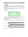
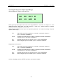
Display for measurement values and setpoints
Example for setting of display 1:
CH1
05.160 mbar
CH2
17.690 sccm
FL2
17.690 sccm
SP2
20.000 sccm
Example for display 2:
The windows above show the format which would come up when following the examples described
in the section Setup.
To ease operation the setpoints SP1 or SP2 can be set here. It is not necessary to enter the setup.
Messages:
OVERFLW
The measurement signal exceeds +11 V. As an example this would be the
case when an absolute pressure transducer with a low full scale range,
e.g. 1 mbar, is connected to this channel and it’s port is open to
atmosphere.
UNDRFLW
The measurement signal exceeds -11 V.
39
Chapter 4: Operation
PR400B-F
Status Displays
RLY1
RTD1
RLY2
RTD2
OK
RLY1, RLY2
A diamond sign indicates if the respective relay is activated.
RTD1, RTD2
A diamond sign indicates if the range turndown function is activated.
OK, EXXX
Error message appears here. Refer to appendix B for a list of error codes
and their interpretation.
Example 1:
OK: no error detected
Example 2:
E002: Error! Can not perform autozeroing
Control Display
AZ1, AZ2
AZ1
VLV1
R1
AZ2
VLV2♦
R2
Zero adjustment (AutoZero) of channel 1 or channel 2 respectively.
To initiate the autozero cycle first indicate the respective channel with the
left/ right arrow key and then press the ENTER key. It is recommended to
check that the readout will be set to zero ( 0 ± 1 Digit). Repeat the autozero
cycle if necessary.
For correct zeroing please read the respective instructions for the
transducers, meters or controllers in use, e.g. thermal stabilization, proper
evacuating of absolute pressure transducers etc.
The PR4000B-F stores the detected offset of the transducer, meter or
controller in use and corrects automatically the reading by this value. In
case of MFC’s or pressure controller the setpoint which is sent out will also
be corrected automatically.
40
PR400B-F
Chapter 4: Operation
During the autozero cycle the display shows ACTIVE followed by a short
report DONE if the procedure was completed successfully.
If the zero offset signal of the meter exceeds ±250 mV the PR4000F will
not perform the autozero process and display FAIL. If this is the case you
should carefully check if all requirements for a correct zeroing are fullfilled
and, if necessary, do a coarse zero adjustment at the meter or transducer.
The zero offset value is displayed in the setup menu in the window OFFS .
When zeroing the type 120 the zero offset values in both ranges are
determined and compensated (provided that the range turndown function
is activated). For more information refer to section Operation with Baratron
Type 120 later in this chapter.
VLV1, VLV2
Applies only to MFC’s and pressure controllers. VLV1, VLV2 are so called
valve switches, that means that a setpoint voltage will only be applied to a
pre-selected channel. Mark the respective channel with the left/right arrow
keys until the cursor appears at the right side of VLVX. Then use either the
up or the down key to generate a diamond sign and confirm with the
ENTER key.
Any channel marked with a diamond can be switched on with the ON key.
This allows to switch on or off channels individually or all channels
simultaneously (Refer also to Note in section 4.6).
R1, R2
In this menu you can switch on or off the indicated relay, e.g. for test
purposes.
Diamond sign activated: relay is activated (switched on)
Diamond sign not activated:
relay is de-activated (switched off)
Note
The setpoint voltage will be applied only to channels which have been
pre-selected with the valve switch VLV1 or VLV2.
4.5. Operation with pressure transducers
If just pressure transducers Baratron series are used it is recommended to simplify the setup
settings by using the default configuration for pressure DEFAULT P : All pressure readouts are set
to mbar, all analog inputs and outputs are set to 10 V. See the table in appendix C for all default
settings. Make sure anyway that the data of your pressure transducer confirm with the defaults,
otherwise change the setup settings where needed.
With setup settings completed and zeroing done, in most cases no more is necessary to be done.
You can immediately start measuring pressure using display 1, configurated for PR1 and PR2.
41
Chapter 4: Operation
PR400B-F
Operation with Baratron Type 120
Range Turndown
This type pressure transducer has a recommended measurement range of five decades, that
means the lowest pressure displayed should be 1E-5 of full scale. The readout of the PR4000F
however will dispIay only four decades thus the lowest pressure displayed would be 1E-4 of full
scale. The type 120 provides a digital input (Range Turndown) which allows, when pulled to low
signal, to increase the output voltage by a factor of ten. The PR4000B-F can support this function
thus enabling the measurement in the range below 10% of the transducer’s full scale range with
full display resolution.
Example for a type 120, 1 mbar full scale
Range
Signal Output
0 ..... 1 mbar,
Range Turndown not active
0 ..... 0,1 mbar, Range Turndown active
0 ..... 10 V; 1 mV equals 1·10-4 mbar
0 ..... 10 V; 1 mV equals 1·10-5 mbar
As explained before the PR4000B-F will display the complete pressure measurement range of the
type 120, with no restriction of the specified resolution, provided the RTD mode has been selected.
To do this the unit will switch at 10 % of full scale automatically the range down. Simultaneously
also the display format switches, so the last digit represents
1E-5 of full scale.
The hysteresis at the switch point is 0,5% of full scale.
For the example given above this means (hysteresis disregarded):
Pressure
Readout
0 ..... 0,1 mbar
0,00000 ..... 0,09999
mbar
active
0,1 ..... 1
0,1000 ..... 1, 0000
mbar
Not active
mbar
RTD
When the autozero cycle is triggered the zero offset of both ranges will be separately determined
and corrected. The zero offset value in any range should not exceed 50 mV. If this is the case, then
carefully check if all requirements for a correct zeroing are fullfilled and, if necessary, do a coarse
zero adjustment directly at the type 120 pressure transducer.
Check after zeroing that the readout displays 0 ± 1Digit. Repeat the autozero procedure if
necessary.
42
PR400B-F
Chapter 4: Operation
4.6. Operation with mass flow controllers (MFC)
For the use with mass flow controllers (MFC) only, it is recommended to simplify the setup settings
by using the default configuration for flow DEFAULT F : All flow readouts are set to sccm, all
analog inputs and outputs are set to 5 V. Most (if not all) parameters to be edited are set to
standard values but should be checked anyway. See the table in appendix C for all default
settings. Change the setup settings where needed.
Always check the correct setting of parameter GAIN to consider the right gas correction factor!
As readouts one will preferably use display 1 and display 2 for displaying both flow and setpoint.
Example: use display 1 for flow readout and display 2 to enter and display the setpoints.
The setpoints can be entered in either the setup menu or in the respectively configurated display.
Note: To activate the setpoint output press the ON key. The activation is indicated by the LED
SETPOINT. Press the key OFF to switch off the setpoint output. If no LED SETPOINT is
activated then none of both channels was pre-selected, that means the valve switch is off.
Refer to the section Control Display, VLV1, VLV2.
Note
The setpoint voltage will be applied only to channels which have been
pre-selected with the valve switch VLV1 or VLV2.
Beside the thermal mass flow controllers also pressure based MFC’s by MKS Instruments type
1150, 1151 and 1152 can be combined to the PR4000B-F.
Control Modes with Mass Flow Controllers:
a. INDEP
Use this mode if the MFC shall be operated independently from the other
channel and setpoints are entered manually through the front panel keys.
b. EXTRN
In this mode the MFC shall be operated independently too but the
setpoint comes from an external signal source.
The range of the external setpoint voltage must be defined in the setup
section for EI1 or EI2 respectively.
The setting of the scaler SCL determines the ratio of the external setpoint
to be applied to the respective channel.
Example for an MFC, control range 0 - 100 sccm, external setpoint
voltage range 0 – 5 VDC. At 5 VDC external setpoint voltage a flow rate
of 40 sccm shall be generated.
Therefore you must set the scaler SCL: 40 sccm !
The external setpoint signal however could be derived from the flow
signal of an other PR4000 sein. This allows for example to configurate
several channels to a gas mixing system.
The value of the external voltage can be displayed: Use the EX mode in
the display configuration (ref. to section Setup).
43
Chapter 4: Operation
c. SLAVE
PR400B-F
If one channel is configurated as a slave then the other channel of the
unit becomes automatically the master of this slave. The slave’s setpoint
is derived from the actual signal of the master. This enables
configurations of gas mixing systems with fixed ratio, e.g. for supplying
gas burners, deposition purposes etc.
An example is given in the SETUP section.
Combinations of these modes are possible.
4.7. Operation with flow meters
For the use with mass flow meters it is recommended to simplify the setup settings by using the
default configuration for flow DEFAULT F : All flow readouts will be set to sccm, all analog inputs
and outputs set to 5 V . Most (if not all) parameters to be edited are set to standard values but
should be checked anyway. See the table in appendix C for all default settings. Change the setup
settings where needed.
Always check the correct setting of parameter GAIN to consider the right gas correction factor!
Because flow meters do not require setpoint signals one could use only display 1 for both flow
readouts FL1 and FL2.
4.8. Operation with pressure controllers
This operation mode mainly affects in line pressure controllers from von MKS Instruments, e.g. the
types 640, 641 or 649. In general the above given instructions for mass flow controllers apply also
here. In some cases the pressure controllers are configured for different voltage input/output
signals, therefore check carefully the conformity of both the controller and the PR4000B-F.
Note
The setpoint voltage will be applied only to channels which have been
pre-selected with the valve switch VLV1 or VLV2.
44
PR400B-F
Chapter 4: Operation
4.9. Limit switches and relays
The two relays on the hardware may be assigned flexible to the channels and different signal
sources. The logic of the limit switches is configurable and also is the hysterisis (i.e. dead band). A
switch delay is not available.
The PR4000B-F provides 5 modes of trip limit operation:
SLEEP
In this mode the trip limits are not active.
LIMIT
In LIMIT mode the signal L is triggered if the actual input is below LL and the signal U is triggered if
the actual input is above UL.
BAND
In BAND mode the signal L is triggered if actual input is below set point minus LL.
And the signal U is triggered if actual input is above set point plus UL.
MLIMIT
Same as Limit mode but including memory capability. The memory can be reset with RESET.
MBAND
Same as Band mode but including memory capability. The memory can be reset with RESET.
45
Chapter 4: Operation
PR400B-F
4.10. Relay Settings
Configuration of relay control is done in the aforementioned menu Limit-Mode in the setup section.
By the use of logical formulas almost each combination of different criteria for activating (or deactivating) the relays can be realized. This allows flexible adoption of both relays to many
demands.
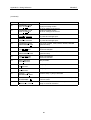
The PR4000B-F supports the following criteria, numbers indicate the respective channel:
R1 / R2
-> Menu parameter for manual relay control (RLY) is switched on.
L1 / L2
-> Signal is below the lower limit value
U1 / U2
-> Signal is above the higher limit value
E1 / E2
-> External digital Input (relay connector) is active
V1 / V2
-> Valve switch (sequential setpoint switch) of the channel is on
D1 / D2
-> RTD line in the range turn down mode is active
T1 - T4
-> Results of 4 temporary formulas to increase the flexiblity of combinations
0 e.g. 1
-> constant values for manual input of criterias
These criteria are combined by logical formulas, e.g. AND, OR etc. oprations. An AND operation
for example means that criteria A and B must be fullfilled to switch the relay.
The PR4000B-F supports the following operations, the symbols in parenthesis show the characters
as they appear on the display:
AND
(^)
Criteria A and B must be fullfilled
OR
(v)
Criteria A or Criteria B or both must be fullfilled
ESCLUSIVE OR
(#)
either Criteria A or Criteria B must be fullfilled (but not both)
NOT
(¬ )
Criteria must not be fullfilled (Negation).
Here are two examples for the use of logic formulas for the relay status:
L1 v ¬ U2
=
L1 OR NOT U2
R1 ^ L1 ^ E1
=
R1 AND L1 AND E1
The PR4000B-F applies these formulas to the relays RLY1 and RLY2. Use the cursor which allows
the following settings dependent from his position (RLY = R1):
Position under " = "
-> Selection of numbers of criteria
Position before or after criteria
-> Choice of operation
Position under a criteria
-> Choice of criteria or of a constant value
Examples:
RLY1 = L1 v ¬ U2
Relay 1 is activated when the signal is below lower limit of channel 1
or high limit of channel 2 is not exceeded
RLY2 = R1 ^ L1 ^ E1
Relay 2 is active when R1 and E1 are activated and signal is below lower
limit of channel 1
46
PR400B-F
Chapter 5: Interface
Chapter 5: Interface
5.1. General
The PR4000B-F offers two serial interfaces, a RS232 and a RS485. The RS232 is a connection
between two devices (Host and PR4000). The RS485 connects the host to up to 30 PR4000, what
makes an address code for each command necessary.
The synchronization between host and PR4000 is maintained by a strict command / reply cycle.
You may only send the next command, if there was a reply received completely.
The parser brings an error on wrong commands, but not on ambiguous commands. In this case it
processes the closest idea of the information received. Terminate command only with <CR>, never
with <CR><LF>.
5.2. Command syntax
The command syntax is defined as follows, were tokens in brackets are optional and token divided
by a separator are alternatives. There are no blanks between command elements needed. Yellow
characters are constant, gray characters represent placeholders for command values.
[@aa][?|!]<cmdc|cmd>[p1[,p2[,p3]]]<CR>
@aa
address with two digit address flag @. This element is only used with the RS485
interface. Delete this element when using the RS 232 port.
E.g. @12 identifies device with address 12.
?
request prefix causes the device to return the actual value of the parameter
identified by cmdc or cmd.
E.g.?DG asks for the actual dialog
!
default prefix causes the device to set the value of the parameter identified by
cmdc or cmd to default.
E.g.!OF1 sets for the offset to zero.
cmd cmdc
command or cahnnel specific command, identifies device parameter or function.
cmdc is with channel specification 1 or 2.
E.g.OF1,0.012 sets for the offset to 0.012.
p1 p2 p3
parameter for the function or command.
E.g.OF1,0.012 0.012. is parameter p1
<CR>
command terminator "carriage return" (13).
,
token separator
47
Chapter 5: Interface
PR400B-F
5.3. Reply syntax
The reply syntax is defined as follows, were token in brackets are optional. There are no blanks
between command elements needed. Yellow characters are constant, gray characters represent
placeholders for command values.
[r1[,r2[,r3]]]<CR>
r1 r2 r3
reply values of command.
<CR>
reply terminator "carriage return" (13).
,
value separator
5.4. Error reply syntax
#Ennn<CR>
nnn
error codes:
#
error escape flag
#E010 syntax error
#E020 FAIL of a command execution, e.g. OF command
<CR>
terminator "carriage return" (13).
48
PR400B-F
Chapter 5: Interface
5.5 Commands
Sample Command
description
command
reply
sample 1
reply 1
sample description 1
sample 2
reply 2
sample description 2
Display Text (DT)
DT[,text]
displays text in the display 4
[text]
text: 32 byte string, which will be written to display 4.
DT,HELLO
display text "HELLO"
?DT
"HELLO"
!DT
return dislayed text
blanks out display
Request Key (KY)
KY
request most recently pressed key
key[,number]
OFF
ESC
RIGHT
UP
No Key
=
=
=
=
=
00007,
00009,
00011,
00013,
00255
ON
= 00008,
ENTER = 00010,
LEFT = 00012,
DOWN = 00014,
Number: 0 ... n
KY
00013
return key code which was pressed most recently. If no
key was pressed since last command then 00225,00000
is returned
?KY
00014,00001
return key code and number of keys, which were not
polled since last command
49
Chapter 5: Interface
PR400B-F
Dialog (DG)
DG[,dialog]
set display to a specific dialog
[dialog]
dialog: dialog index. See also Appendix D Dialog
Reference
DG,2
set display do dialog #2
?DG
00004
return actually displayed dialog
ID String (ID)
retrieve ID string
format: vv
= version
rr
= release
sssss = serial number
ID
PR42vvrrsssss
ID
PR42012900000
returns ID string
?ID
PR42012900000
returns ID string
Remote Mode (RT)
RT[,enable]
set to remote operation
[enable]
enable: OFF, ON
RT,ON
switch PR4000 to remote mode
?RT
ON
RT,OFF
ask for remote mode
switch PR4000 to local mode
Access Channel (AC)
ACc[,setpoint[,vlv]]
access channel
setpoint, actvalue: -5% .. 110% of FS (formatted in
selected range)
vlv: OFF, ON
actvalue[,vlv]
AC1,100.00
-010.00
set setpoint of channel 1 and retrieve actual value
AC2,100.00,ON
099.99
set setpoint of channel 2, enable channel valve and
retrieve actual value.
?AC1
099.99,ON
retrieve actual value
50
PR400B-F
Chapter 5: Interface
Actual Value (AV)
AVc[,setpoint]
get actual value
actvalue
setpoint, actvalue: -5% .. 110% of FS
selected range)
AV1
099.99
retrieve actual value
AV1,50.0
099.99
retrieve actual value and set setpoint
(formated in
Setpoint (SP)
SPc[,setpoint]
set setpoint
[setpoint]
setpoint: -5% .. 110% of FS (formated in selected range)
SP1,50.0
set setpoint
?SP1
050.00
retrieve setpoint
External Input (EX)
EXc
access of EXTERN channels
extinput
extinput: -5% .. 110% of FS (formated in selected range)
EX1
000.00
retrieve external input
Status (ST)
ST
request of hex status word
hexsts
hexsts bits:
ST
00128
retrieve status
51
0
1
2
3
4
5
6
7
=
=
=
=
=
=
=
=
comerr;
underrange AIN0;
overrange AIN0;
underrange AIN1;
overrange AIN1;
relay0;
relay1;
parameter changed by user
Chapter 5: Interface
PR400B-F
Valves (VL)
VLc[,enable]
set channel specific valve status
[enable]
enable: OFF, ON
VL1,ON
set valve of channel 1
VL0, OFF
disable valve of both channels
?VL1
ON
retrieve vavle status of channel 1
Relays (RL)
RLc[,enable]
set manual setting of relay
[enable]
enable: OFF, ON
RL1,ON
set relay 1
?RL1
ON
retrieve relay 1 status
Displays (DP)
DPd,(line,tag,chn|enable)
setup configurable displays
(tag,chn)| OFF
line:
1, 2
tag:
0=SP, 1=VA, 2=CH, 3=FL, 4=PR, 5=EX
chn = 1, 2
enable: OFF, ON
DP1,1,3,1
?DP1,1
DP2,OFF
sets display 1, line 1 to FL of channel 1
3,1
retrieve setting of display 1
switch display 2 off
Display 4 (DP4)
DP4[,enable]
setup configurable display 4
[enable]
enable: OFF, ON
DP4,ON
switch display 4 on
52
PR400B-F
Chapter 5: Interface
Range (RG)
RGc[,range,unit]
setup range and engineering units
[range,unit]
range : 5 digits
unit:
ubar
mTor
Pa
cH2O
SCCM
SCFH
V
RG1,5.0,12
?RG1
5.0000,00012
=
=
=
=
=
=
=
0
mbar
=
1
bar
3
Torr
=
4
KTor
6
kPa
=
7
mH2O
9
PSI
=
10
N/qm
12
SLM
=
13
SCM
15
SCFM =
16
mA
18
%
=
19
C
set range of channel 1 to 50 SCCM
retrieve range and unit
Gain (GN)
GNc[,gain]
setup gain
[gain]
gain: 0,001 .. 2.000
GN1,1.3
set gain of channel 1
?GN1
01.300
retrieve gain
Offset (OF)
OFc[,offset]
setup offset
[offset]
offset: -250 .. +250
OF1,30
set offset of channel 1
?OF1
00030
retrieve offset
RTD Offset (RO)
ROc[,offset]
setup RTD offset
[offset]
offset: -250 .. +250
RO1,3
set offset of channel 1
?RO1
00003
retrieve offset
53
=
=
=
=
=
=
=
2
5
8
11
14
17
20
Chapter 5: Interface
PR400B-F
Autozero (AZ)
AZc
trigger autozero
offset
offset: -250 .. +250
AZ1
00003
perform autozero function of channel 1.
Input Range (IN)
INc[,phyrange]
setup of physical input range
[phyrange]
phyrange: 1 .. 10
IN1,10
set input range of channel 1 to 10 V
?IN1
00010
retrieve input range
Output Range (OT)
OTc[,phyrange]
setup of physical output range
[phyrange]
phyrange: 1 .. 10
OT1,10
set output range of channel 1 to 10 V
?OT1
00010
retrieve output range
External Input Range (EI)
EIc[,phyrange]
setup of physical input range
[phyrange]
phyrange: 1 .. 10
EI1,10
set external input range to 10 V
?EI1
00010
retrieve external input range
External Output Range (EO)
OTc[,phyrange]
setup of physical output range
[phyrange]
phyrange: 1 .. 10
OT1,10
set external output range to 10 V
?OT1
00010
retrieve external output range
54
PR400B-F
Chapter 5: Interface
Signal Mode (SM)
SMc[,smode]
setup of signal mode
[smode]
smode:
0 = METER,
4 = SLAVE,
SM1,2
?SM1
1 = OFF,
5 = RTD,
2 = INDEP,
3 = EXTRN,
set signal mode to independent
00002
retrieve signal mode
Scale (SC)
SCc[,scale]
setup of scale
[scale]
scale: -5% .. 110% of FS (formatted in selected range)
SC1,30.0
set scale
?SC1
30.000
retrieve scale
Linearization (LN, LS)
LNc[,point,x,y]
setup of linearization table
[x,y]
point: 0 .. 10
x, y: -5% .. 100% of FS (formatted in selected range)
LN1,2,2.1,2.2
?LN1,2
set point of lin. table
02.000, 02.000
retrieve point in lin. table
LSc[,size]
setup of table size
[size]
size: 0 ..10
LS1,2
set table size
?LS1
00002
retrieve table size
Limit Mode (LM)
LMc[,lmode]
setup limit mode
[lmode]
lmode: 0 = SLEEP,
LM1,1
?LM1
1 = LIMIT,
2 = BAND,
set limit mode
00001
retrieve limit mode
55
3 = MLIMIT,
4 = MBAND
Chapter 5: Interface
PR400B-F
Dead Band (DB)
DBc[,deadband]
setup of dead band(HY is an alias )
[deadband]
deadband: 0.0% .. 9.9% of FS
DB1,1.2
set dead band
?DB1
01.200
retrieve dead band
Upper Limit (UL)
ULc[,upperlimit]
setup of upper limit
[upperlimit]
upper limit: -5% .. 110% of FS (formatted in selected range)
UL1,80.0
set upper limit
?UL1
80.000
retrieve upper limit
Lower Limit (LL)
LLc[,lowerlimit]
setup of lower limit
[lowerlimit]
lower limit: -5% .. 110% of FS (formatted in selected range)
LL1,20.0
set lower limit
?LL1
20.000
retrieve lower limit
Formula Relay (FR)
FRr[,[neg]src [op[neg]src] [op[neg]src]]
setup of relay source
[[neg]src [op[neg]src] [op[neg]src]]
r:
Number of formula (1, 2).
neg:
Sign for negation is !
src:
R1,R2,L1,L2,U1,U2,E1,E2,V1,V2,
D1,D2,T1,T2,T3,T4,1,0
op:
Operator (+ is OR, * is AND,
x is XOR)
FR1,!R1+!T4+D1
?FR1
set formula
!R1+!T4+ D1
retrieve actual formula
56
PR400B-F
Chapter 5: Interface
Formula Temporary (FT)
FTt[,[neg]src [op[neg]src] [op[neg]src]])
setup of temporary formula
[[neg]src [op[neg]src] [op[neg]src]]
t: Number of formula (1, 4)
The rest is the same except that the four sources
T1,T2,T3,T4 are not available.
FT1,!R1+!T4+D1
set formula
?FT1
!R1+!T4+ D1
retrieve actual formula
Parity (PY)
PY[,parity]
setup of parity
[parity]
parity: 0=NONE, 1=EVEN, 2=ODD
PY,2
set parity
?PY
00002
retrieve parity
Baudrate (BD)
BD[,baudrate]
setup of baudrate
[baudrate]
baudrate: 0 = 110,
5 = 19k2,
BD,4
?BD
1 = 1200,
6 = 38k4,
2 = 2400,
7 = 57k6,
3 = 4800,
8 = 76k8,
set baudrate
00004
retrieve baudrate
Address (AD)
AD[,address]
setup of address
[address]
address: 0 .. 31
AD,4
set address
?AD
00004
retrieve address
Interface Mode (IM)
[ifacemode]
setup of interfacemode
this command is not used at the moment
IM,4
set interface mode
IM[,ifacemode]
?IM
00004
retriev interface mode
57
4 = 9600,
9 = 110k
Chapter 5: Interface
PR400B-F
Resolution (RS)
RS[,enable]
setup of 16 bit resolution
[enable]
enable: OFF, ON
RS,ON
set resolution to 16 bit
?RS
ON
retrieve resolution
Reset Status (RE)
RE
reset status
RE
reset status
Default (DF)
DF,dmode
reset to default values (Pres|Flow)
dmode: P=pressure, F=flow
DF,P
set pressure default
Unlock (#0)
#0
unlock setup
Lock (#1)
#1
lock setup, access possible
Tweak Control ($0, $1, ?$)
$0
switch off Tweak Control, e.g. for pressure controller type 640
$1
switch on Tweak Control
?$
test Tweak Control status
?$
0
correct for pressure controller 640
58
PR400B-F
Appendix A: Specifications
Appendix A: Specifications
Number of channels
2 inputs for flow or pressure signals
2 inputs for external setpoints
2 outputs for setpoints
2 outputs for signal monitoring
Accuracy
0,01% ± 1 Digit
Temperature coefficient
Input:
Output:
0,1 mV / K (Ra < 1 Ω
0,075 mV / K
Display format and resolution
Two line LCD, 16 places per line , configurable:
4-digits: 0000 – 9999 (12 bit resolution)
5-digits: 00000 - 99999 (16 bit resolution)
Conversion rate Mode:
EXTERN
Rate:
5 Hz at
20 Hz at
not EXTERN
16 bit
12 bit
20 Hz
Signal input range (all)
±11 V, to be scaled in steps of 1 V
Signal output range (all)
±11 V, to be scaled in steps of 1 V
Relays
2 Relays, SPDT; 220 VDC, 125 VAC,2 A;
can be combined with any channel
Interface
Standard: RS232
Option:
RS485
Power output
Standard: ±15 V; 1,5 A
Option:
24 V; 1 A
Input power
85 - 265 V; 47 - 63 Hz
Operation temperature
15 – 40 °C
CE, RoHS
yes
Housing
½ x 19” Rack Mounting or top on table use
Weight:
2,4 kg
59
Appendix A: Specifications
PR400B-F
This page left blank.
60
PR400B-F
Appendix B: Error Messages
Appendix B: Error Messages
Code
Problem
E 001
Communication Error
E 002
ADC Overflow or Underflow
E 003
Range Error, Setpoint < 0 or out of Range
W 001
Offset > 250 mV
61
Appendix B: Error Messages
PR400B-F
This page left blank.
62
PR400B-F
Appendix C: Default-Configuration
Appendix C: Default – Configuration
Parameter
Default Flow
Default Pressure
DISPLAY1, 2
FL1, SP1; FL2, SP2
PR1, PR2; off
DISPLAY3, 4
off, off
off, off
SP1, SP2
100%, 100%
0%, 0%
RNG1, RNG2
100SCCM, 100SCCM
10mbar, 10mbar
GAIN1, OFFS1
1.0, 0mV
1.0, 0mV
GAIN2, OFFS2
1.0, 0mV
1.0, 0mV
RTDOFFS1, RTDOFFS2
0mV
0mV
IN1, OUT1, EI1, EO1
5V, 5V
10V, 10V
IN2, OUT2, EI2, EO2
5V, 5V
10V, 10V
SIGMODE1, SCL1
INDEP, 100%
METER, 0%
SIGMODE2, SCL2
INDEP, 100%
METER, 0%
LIN1
1:1; zero points
1:1; zero points
LIN2
1:1; zero points
1:1; zero points
LIM MODE1, DEAD BAND1
SLEEP, 0.0%
SLEEP, 0.0%
UL1, LL1
20%, 80%
20%, 80%
LIM MODE2, DEAD BAND2
SLEEP, 0.0%
SLEEP, 0.0%
UL2, LL2
20%, 80%
20%, 80%
RLY1, RLY2
0, 0
0, 0
T1, T2
0, 0
0, 0
T3, T4
0, 0
0, 0
BAUDRATE, PARITY
9600, ODD
9600, ODD
ADDRESS, IFACEMODE
0, 0
0, 0
RESOL16
no
yes
63
Appendix C: Default-Configuration
PR400B-F
This page left blank.
64
PR400B-F
Appendix D: Dialog Reference
Appendix D: Dialog Reference
Index
Dialog
Comment
0
tgc $display
tgc $display
configurable display 0
1
tgc $display
tgc $display
configurable display 1
2
tgc $display
tgc $display
3
XXXXXXXXXXXXXXXX
XXXXXXXXXXXXXXXX
user display
4
RLY1b RTD1b err
RLY2b RTD2b cmd
status display for relays, RTD, system errors and
display recent interface command, ack. with ENTER
5
AZ1 VLV1b R1b
AZ2 VLV2b R2b
autozero trigger and switches for valves and relays.
6
SETUP
RESET
V01.28 19991001
enter setup mode, reset status
version and generation date (__DATE__)
7
DISPLAY1 tgc tgc
DISPLAY2 tgc tgc
setup of display 1, 2; if both tags are off the display is
not visible (DISPLAY2 may be switched off)
8
DISPLAY3 tgc tgc
DISPLAY4 b
setup of display 3, 4;
(DISPLAY3&4 may be switched off)
9
SP1 sd.dddd unit
SP2 sd.dddd unit
setpoint setup
10
RNG1 d.dddd unit
RNG2 d.dddd unit
range setup (last digit may be suppressed for 3.5 digit
display)
11
GAIN1 sddd.dddd
OFFS1 sddddd mV
gain (7 digits), offset chn1.
(0.001 < gain < 2.000); (-250mV < offset < 250mV)
12
GAIN2 sddd.dddd
OFFS2 sddddd mV
gain (7 digits), offset chn1.
(0.001 < gain < 2.000); (-250mV < offset < 250mV)
13
RTDOFFS1 sddd mV
RTDOFFS2 sddd mV
RTD offset
14
IN1 er OUT1 er
EI1 er EO1 er
full scale I/O ranges chn1.
15
IN2 er OUT2 er
EI2 er EO2 er
full scale I/O ranges chn2.
configurable display 2
to be continued on next page
65
Appendix D: Dialog Reference
PR400B-F
(continued)
Index
Dialog
Comment
16
SIGMODE1 smode
SC1 sd.dddd unit
17
SIGMODE2 smode
SC2 sd.dddd unit
signal processing modes
SC is for scaling of the source
18
LIN1 pt ln unit
sd.dddd<>sd.dddd
linearization table chn1:
11 points and a length spec.
19
LIN2 pt ln unit
sd.dddd<>sd.dddd
linearization table chn1:
11 points and a length spec.
20
LIM MODE1 lmode
DEAD BAND 1 d.d%
limit mode: SLEEP, LIMIT, BAND, MLIMIT, MBAND
hysterisis setup
21
UL1 sd.dddd unit
LL1 sd.dddd unit
upper limit definition
lower limit definition
22
LIM MODE2 lmode
DEAD BAND 2 d.d%
limit mode: SLEEP, LIMIT, BAND, MLIMIT, MBAND
hysterisis setup
23
UL2 sd.dddd unit
LL2 sd.dddd unit
upper limit definition
lower limit definition
24
RLY1=$formula
RLY2=$formula
relay formulas
25
T1=$formula
T2=$formula
temporary formulas
26
T3=$formula
T4=$formula
temporary formulas
27
PARITY
prty
BAUDRATE baud
interface setup 1: parity & baudrate
28
ADDRESS
aa
IFACEMODE dd
interface setup 2: adress and interface mode; if (aa>0)
then bus mode
29
RESET DEFAULT d
RESOL16 b EXIT
reset to default, reset status, exit setup,
setup of 12/16 Bit resolution
signal processing modes
SC is for scaling of the source
66
PR400B-F
MKS Worldwide Calibration & Service Centers
MKS Worldwide Calibration & Service Centers
UNITED STATES
GERMANY/BENELUX
MKS Instruments, Inc.
Corporate Service Center
90 Industrial Way
Wilmington, MA 01887-4610
Tel (978) 284-4000
Fax (978) 284-4303
MKS Instruments,
Deutschland GmbH
Schatzbogen 43
D-81829 München
Tel 49-89-420008-0
Fax 49-89-42-41-06
Email: [email protected]
MKS Instruments, Inc.
HPS Division,
Vacuum Components,
Valves & Gauging
5330 Sterling Drive
Boulder, CO 80301
Tel (303) 449-9861
Fax (303) 449-2003
ITALY
G. Gambetti Kenologia Srl.
Via A. Volta No. 2
20082 Binasco (MI), Italy
Tel 39-2-90093082
Fax 39-2-905.2778
JAPAN
CANADA
MKS Japan, Inc.
Harmonize Building
5-17-13, Narita-Higashi
Suginami-Ku, Tokyo 166, Japan
Tel 81-3-3398-8219
Fax 81-3-3398-8984
MKS Instruments, Canada Ltd.
30 Concourse Gate
Nepean, Ontario, Canada K2E 7V7
(613) 723-3386
Tel (800) 267-3551 (CAN only)
Fax (613) 723-9160
KOREA
FRANCE
MKS Korea Co., Ltd.
1st Floor DK Plaza-I
375-1 Geumgok-dong
Bundang-gu,Seongnam Kyonggi-do
Korea 463-805
Tel 82-31-717-9244
Fax 82-31-714-9244
MKS Instruments, France s.a.
43, Rue du Commandant Rolland
B.P. 41
F-93352 Le Bourget, Cedex,
France
Tel 33(1)48.35.39.39
Telex 233817 F
Fax
33(1)48.35.32.52
UNITED KINGDOM
MKS Instruments, U.K. Ltd.
1 Anchorage Court
Caspian Road
Altrincham, Cheshire
WA14 5HH, England
Tel 44-161-929-5500
Fax 44-161-929-5511
DENMARK
MKS Denmark ApS
Ndr. Strandvej 119G
DK-3150 Hellebæk
Tel 45-44 92 92 99
Fax 45-44 92 94 99
Email: [email protected]
SINGAPUR
TAIWAN
MKS Instruments, Inc.
BLK 4010 Techplace I
#01-08/09 Ang Mo Kio Avenue 10
Singapore 569623
Tel (65) 6451 1062
Fax (65) 6451 0172
MKS Instruments, Taiwan
10F, No.93, Shoei-Yuan Street
Hsinchu City 300
Taiwan, R.O.C.
Tel 886-3-575 3040
Fax 886-3-575 3048
67