1
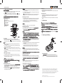
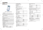
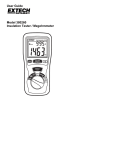
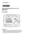
Ⅲ.Product Features
GDM-452
1.
2.
3.
4.
5.
6.
7.
30 ranges for function selection;
Over-range display: "1";
Display count: 19999;
Fast-acting fuse protection for current ranges: 200mA and 10A;
Full-range overload protection;
Auto power off;
Temperature range:
Operating: 0℃~ 40℃(32℉ ~ 104℉);
Storage: -10℃~ 50℃(14℉ ~ 122℉);
8. Altitude: ≤ 2,000m;
9. Low Battery Indication: “ ” displays;
10. Dimensions: 186×91×39mm;
11. Weight: About 300g (not including test leads).
AC Current
Ⅳ.Technical Specifications
b digits
True RMS v
Resistance
DC Voltage
Ⅰ.Introduction
The GDM-452 is a 20000-count handheld digital multimeter
with remarkably stable and reliable operation. It is mainly
supported with a dual integral A/D converter based on CMOS technology
and also offers overload protection for all ranges. This model can
measure DC&AC voltage, DC&AC current, resistance, capacitance,
diode, transistor, frequency and continuity.
RMS
AC RMS
Ⅱ.Safety Information
The GDM-452 is designed and manufactured in compliance with:
IEC61010-1, CATⅠ1000V, CATⅡ600V and CATⅢ300V overvoltage
standards.
Warnings
Use the meter as specified in the manual , otherwise the protection
offered by the multimeter may be impaired.
● Do not use the multimeter with back cover opened, it may cause
electric shock.
● Set to a proper range for your measurement.
● Check the test leads for any damaged insulation or broken wires.
● Insert red and black test leads into proper input terminals and ensure
good contact between them.
● Do not input signal beyond the rated values of the multimeter,
otherwise it may cause electric shock or damage to the multimeter.
● Prohibit switching the range during the voltage or current
measurement, for it may cause damage to the multimeter.
● Please use replacement parts with the same model or similar electrical
specifications.
● To avoid electric shock, Do not apply any voltage above 1000V
between COM and grounding.
● Please take caution when working voltage goes above 60VDC or
30VAC RMS.
● To ensure the accuracy, please replace the batteries as soon as appears.
● Shut off the power timely after the measurements complete. Take out
the batteries if not used for a long time.
● Do not use the multimeter in places exposed to high temperature, high
moisture. The performance of the multimeter may be compromised if
moisture-affected.
● To prevent damage to the multimeter or personal injury, do not alter
internal wiring randomly.
● Clean the multimeter casing with slightly damped soft cloth and mild
agent. Do not use any abrasives and corrosives.
International Electrical Symbols
Low Battery Indication
Double Insulated
Conforms to European Union Standards
AC Voltage
About 3V (for 200Ω range);
Note: please short-circuit the test leads when using 200 Ω range to
measure, and subtract this shorted value from all subsequent measured
values so as to obtain accurate reading.
Capacitance
AC RMS
Frequency
Effective average value
DC Current
Diode and Continuity
Display approximate value
of forward voltage drop for
diode
If resistance≤30Ω, the
buzzer sounds; Display
approximate kΩ value.
P/N:82DM-45200M01
Ⅴ.Making Measurements
(1) Power on the Multimeter and inspect 9V battery. Replace the battery
if “
” displays. If not, proceed into next step.
(2) Pay attention to rated voltage or current value next to “
” near
input terminals, any input that go beyond the rating may damage the
Multimeter.
1. Set to the maximum range and reduce it gradually if the measured
current is unknown.
2. If "1" displays on LCD, it indicates over-range, please select a higher
range for your measurement.
3. “
” indicates the maximum input current. mA input is protected by
200mA/250V fuse; 10A/250V fuse is used to protect 10A range.
Measuring AC Current
LCD display
POWER button
CANCEL AUTO POWER OFF button
AC+DC button
HOLD button
1. Insert black test lead into COM jack and insert red one into mA jack if
measured current is not more than 200mA. insert red test lead into
10A jack if measured current is between 200mA and 10A.
2. Place function switch at A~ range and connect testing leads to
measurement loop in series.
Data Hold
1. Press HOLD button to realize such function;
2. Whether the test leads are disconnected or not will not influence Data
Hold function.
Auto Power Off
1. The Multimeter is designed with automatic power-off circuit to power
off after instrument operates for about 15 minutes and enter into
sleeping status;
2. Press POWER button twice to wake up the Multimeter from the sleep
mode.
Ⅵ.Maintenance
This kind of Multimeter belongs
1. Please refer to “Notice” for DC current measurement.
Input jack
1000VDC or 750Vrms AC.
Measuring Resistance
1. Insert black test lead into COM jack and insert
2. Place function switch
leads to
“current ranges”
removing test leads
Ⅶ.Replacing the Battery
DC Current
1. Insert test leads into input jacks(Red to V and black to COM).
2. Set the function switch to V
range; Connect test leads to the wire
under test in parallel, and the positive polarity of the test end will indicate.
Notice
1. Set to the maximum range and reduce it gradually if the measured
voltage is unknown.
2. If "1" displays on LCD, it indicates over-range, please select a higher
range for your measurement.
3. “
” indicates not to input voltage higher than 1000V, which may
cause damage to the Multimeter or personal injury although the reading
may be obtained.
4. Extreme care should be taken to avoid electric shock when measuring
high voltage.
Measuring Capacitance
1. Insert the tested capacitor directly into capacitance jacks(without need
of test leads).
2. The floating reading exists every time you switch to another
capacitance range and reset to zero before connecting to a tested
capacitor, which however will have no impact on the accuracy.
1. Discharge the tested capacitor before measurement, although the
capacitance ranges are protected internally, it may also cause damage
to the multimeter.
Measuring AC Voltage
1. Insert black test lead into COM jack and insert red one into V jack;
2. Place function switch at V~ range scope and then connect test leads
to measurement wires in parallel.
may cause damage to internal wires
Measuring DC Current
1. Insert black test lead into COM jack and insert
not more than 200mA. Insert the red test lead into
10A jack if measured current is between 200mA and 10A.
2. Place function switch at A
range and then connect testing leads
to measurement loop in series. It will dispaly current and polarity of
red test lead at the same time.
Ⅷ.Accessories
Measuring Frequency
1. Insert red test leads into HZ jack and insert black one into COM jack;
2. Place function switch at kHZ range and connect test leads to frequency
Test Leads
1 pc
The accuracy cannot be ensured if input signal voltage is higher than
30Vrms, and please take extreme care.
Testing Diodes and Continuity
Insert black test lead
test leads
Connect test leads
This manual contains proprietary information, which is protected by copyright. All
rights are reserved. No part of this manual may be photocopied, reproduced or
translated to another language without prior written consent of Good Will company.
The information in this manual was correct at the time of printing. However, Good Will
continues to improve products and reserves the rights to change specification,
equipment, and maintenance procedures at any time without notice.
Good Will Instrument Co., Ltd.
No. 7-1, Jhongsing Rd., Tucheng Dist., New Taipei City 236, Taiwan