1
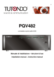
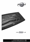
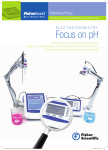
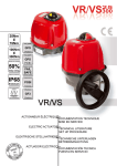
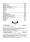
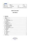
RGBW
bar
User’s and operator’s manual for art. 0901
Manuale d’uso e dell’operatore per art. 0901
INDEX / INDICE
Safety informations:
Precauzioni di sicurezza: .........................................................
pag. 3
Introduction:
Introduzione: .........................................................................
pag. 4
Technical features:
Caratteristiche tecniche: ..........................................................
pag. 5
Main power connection:
Collegamento fonte di alimentazione: ....................................
pag. 6
DMX signal connection:
Collegamento segnale DMX: ...................................................
pag. 6
Control panel FUNCTIONS:
FUNZIONI del pannello di controllo: ........................................
pag. 7
EXAMPLE connection DMX controller-spot:
Esempio di collegamento centralina DMX-fari: ......................
pag. 7
DMX Listing:
Lista dei valori DMX: ................................................................
pag. 8
Built in programs:
Lista giochi: .................................................................................. pag. 9
Technical drawings - part list:
Disegni tecnici - lista delle parti: ................................................. pag. 10
Warranty:
Garanzia: .....................................................................................
pag. 14
CE standards:
Dichiarazione CEi: ......................................................................
pag. 15
bar
rel.1/05.09
2
eng
!
WARNING
SAFETY INFORMATION (service personnel)
Read all cautions and warnings prior to operate this equipment.
Instruction to prevent injury or damage due to electric shock, fire, mechanical hazards,
DANGEROUS MATTERS.
•PROTECTION AGAINST DANGEROUS MATTERS
At the end of its working life, the product must not be disposed of as urban waste. It must be taken to a special local
authority differentiate waste collection centre or to a dealer providing this service. The wrong disposal must be cause
of environment and people damages in the presence of possible dangerous matters. There are provided for sanctions
to a unauthorized disposal of these products.
•PROTECTION AGAINTS FIRE
1) Maintain minimum distance of 0.3 meter from walls or any other type flammable surfaces.
2) Maintain minimum distance of 1.0 meter to lighted objects .
3) Replace fuses (if present) only with the specified type and rating.
4) Do not install the spot close to heat sources. Do not lay the connection cable on the spot when it is warm.
5) Fixture designed to be installed on normally flammable surfaces.
•PROTECTION AGAINST ELECTRIC SHOCK
1) This equipment must be earthed.
2) Class I equipment. The power supply cord includes a protective earthing conductor as part of the cord.
3) Disconnect power before servicing (service personnel).
•PROTECTION AGAINST MECHANICAL HAZARDS
1) Use secondary safety chain when fixing this equipment.
2) Equipment surface may reach temperature up to 40°C.
3) The protection screens and the lenses must be replaced with genuine parts only
if they are visibly damaged and their effectiveness has been
reduced, for example, by cracks or deep scratches.
1m
F
ita
!
IMPORTANTE
INFORMAZIONI DI SICUREZZA (personale di servizio)
Leggere attentamente tutti gli avvertimenti prima di compiere qualunque operazione su questo
apparecchio. istruzioni per prevenire lesioni o danni dovuti al fuoco, alle scosse elettriche,
ai rischi meccanici ED A SOSTANZE PERICOLOSE.
•PROTEZIONE CONTRO SOSTANZE PERICOLOSE
Questo prodotto a fine vita è oggetto di raccolta separata, non gettare nei comuni cassonetti di rifiuti urbani, né
tantomeno nell’ambiente. Può essere consegnato presso gli appositi centri di raccolta differenziata predisposti dalle
amministrazioni comunali, oppure presso i rivenditori che forniscono questo servizio. Lo smaltimento errato può causare danni alle persone e all’ambiente per la possibile presenza di sostanze pericolose. Sono previste sanzioni in caso
di smaltimento abusivo dei suddetti prodotti.
•PROTEZIONE CONTRO IL FUOCO
1) Mantenere la distanza minima di 0.3 metri da pareti ed altre superfici infiammabili.
2) Mantenere la distanza minima di 1.0 metri dagli oggetti illuminati.
3) Sostituire i fusibili (se presenti) solo con altri dello stesso tipo e valore.
4) Non installare il faro vicino fonti di calore. Non appoggiare il cavo di connessione sul faro quando questo è caldo.
5) Questo apparecchio è adatto per il montaggio su superfici normalmente infiammabili.
•PROTEZIONE CONTRO SCOSSE ELETTRICHE
1) Questo apparecchio necessita di messa a terra.
2) Apparecchio di Classe I. Il conduttore di protezione deve far parte del cavo di alimentazione.
3) Disconnettere l’alimentazione prima di aprire l’apparecchio (personale di servizio).
•PROTEZIONE CONTRO RISCHI MECCANICI
1) Usare la catena di sicurezza supplementare quando installate il faro.
2) La temperatura dell’apparecchio può raggiungere 40°C.
3) Gli schermi di protezione e le lenti devono essere sostituiti sempre con ricambi originali
se sono visibilmente danneggiati e se la loro efficacia è stata ridotta, per esempio, da fessure o incisioni profonde.
3
1m
F
rel.1/05.09
eng
INTRODUCTION
Thanking for using ArchiBar250.
ArchiBar250 is an RGBW flood projector, which has been created for indoor static architectural purpose. It’s small and compact
size to reduce visual obstruction but without reducing performance. 16 powerful 5W leds total with 4 separate groups (each group
can work separately) to create numberless scenes and color games.
The ArchiBar250 comes in the following versions:
•Art. 0901 RGBW ArchiBar250 (rgbw)
•Art. 09011 W+A ArchiBar250 (white+amber)
To make the most of its possibilites and for a correct functioning of this unit in the years to come, we suggest you to read carefully
this manual before connecting or putting the spot into use. By doing so you will gain experience with its commands and connections
and you will be easily able to use it.
Your reference
Always remeber to give the serial number and to specify the model any time you address the seller for information or assistance.
Basic Kit
• Projector
• User’s manual
• Studio Due warranty
example
!
WARNING
Check that the spot has not been damaged during transport. If it has been damaged or it does not work, address
the seller. Whether the spot has been shipped to you directly, please contact the shipping company.
Only the consignee (person or company) can claim for these damages.
ita
INTRODUZIONE
Vi ringraziamo per l’ utilizzo dell’ArchiBar250.
ArchiBar250 è un proiettore LED RGBW progettato per installazioni architetturali per uso interno. E’ piccolo, compatto e discreto
nelle applicazioni ma senza pregiudicare le sue performance.
Un totale di 16 potenti RGBW leds da 5W, suddivisi in 4 gruppi che possono operare separatamente, permettono di creare numerose scene e giochi di colore.
ArchiBar250 viene prodotto nelle seguenti versioni:
•Art. 0901 RGBW ArchiBar250 (rgbw)
Per ottenere il meglio delle prestazioni ed un corretto funzionamento negli anni di questa unità, Vi consigliamo di leggere attentamente questo manuale prima di collegarla e metterla in uso. In questo modo acquisirete familiarità con i suoi comandi e collegamenti
affinché possiate utilizzarla facilmente.
VOSTRA REFERENZA
Citate il numero del modello e di serie ogni volta che Vi rivolgete al vostro rivenditore per informazioni o assistenza.
CONFEZIONE BASE
• Proiettore
• Manuale d’uso
• Garanzia Studio Due
esempio
!
IMPORTANTE
Controllate che l’apparecchio non abbia subito alcun danno durante il trasporto.
Se avesse subito dei danni o se non dovesse funzionare, rivolgetevi al vostro rivenditore.
Se l’apparecchio vi è stato spedito direttamente, rivolgetevi subito alla ditta di trasporto.
Solo il destinatario (la persona o ditta ricevente l’apparecchio) può reclamare per questo tipo di danni.
rel.1/05.09
4
Technical features / CARATTERISTICHE TECNICHE
LED / LED: (5W powerful Luxeon Rebel leds)
16 rgbw subdivided in 4 groups, each one of them can work separately. High efficient lenses allow a progressive and gradual coloring of the entire light beam, which can therefore continuously reach endless shades and color saturation. Rainbow effect.
16 gruppi di rgbw leds suddivisi in 4 gruppi ogniuno. Ogni gruppo da 4 può lavorare separatamente.
Le lenti ad alta efficienza che garantiscono una colorazione progressiva e graduale dell’intero fascio di luce, consentendo così un’infinità di colori e una completa saturazione della luce. Effetto rainbow.
OPTIC / OTTICA
Medium beam at 25°. Ottica media 25°.
On request, wide beam 40° lenses. A richiesta, ottica larga 40°
CONTROL INPUT / segNALE di controllo
Standard interface RS-485, opto-coupled input, protocol: USITT DMX 512; 21 - 16 - 9 or 4 channels mode.
Interfaccia standard RS-485, ingresso opto-isolato, protocollo: USITT DMX 512; modo 21 - 16 - 9 o 4 canali.
Setup & Configuration / CONFIGURAZIONE
16 bit led dimming for precise color mixing. Built-in programs for fixture can allow the fixture to work singularly or synchronize with other fixtures, also without DMX control, the user can obtain the required scenery by choosing the proper stored programs (see the preset page).
Miscelazione colore precisa a 16 bit. Programmi residenti per poter utilizzare l’apparecchio singolarmente o sincronizzato con altri apparecchi anche tramite centralina di controllo (vedere la pagina dei giochi).
Possibilità di realizzare vari giochi di luce scegliendo il programma residente appropriato.
DMX DATA CABLING
Outdoor type cable with rubber seals 2 conductor twisted pair plus a shield (24AWG or larger) suitable for EIA 485 (RS485) standard.
To avoid signal transmission problem, a cable for high-speed data transmission is necessary.
A 100-Ohm terminator resistor fitted between the two “data” lines (pin 2 and 3 of the 3 pins connector) at the end of cable.
The use of normal microphone or audio cable is suggested for cable connection that is shorter than 100 meter.
For cable connection longer than 150-200m, the use of a signal amplifier is suggested.
IP RATE / gardo di protezione
Fixture for indoor use only. Apparecchio per utilizzo all’interno.
STROBE / BLACKOUT/DIMMER
Blackout and strobe effect with linear speed (min. 0,5 flash/sec. max. 25 flash/sec.) + dimmer: 0÷100%
Oscuramento con effetto strobo a frequenza regolabile (min. 0,5 flash/sec. max 25 flash/sec.) + funzione dimmer: 0÷100%
AUTO MODE / MODO AUTOMATICO
With Master/Slave functions / con funzione Master/Slave
TILT:
Up to 110° of head rotation. Fino a 110° di rotazione della testa.
MAINS POWER SUPPLY / ALIMENTAZIONE: (Electronic switching power supply / alimentatore elettronico universale)
• Rated voltage / Tensione di rete
: 100-240 V~ / 50-60 Hz
• Rated wattage / Assorbimento : 300 VA
• Rated current / Corrente : 1,5A @ 230V~
• Fuse/ Fusibile : 3,15AT
WEIGHT / peso : 8,7 Kg.
DIMENSIONS / DIMENSIONI: (WxDxH) 1005x180X255 (max)
Safety
The safety specifications listed are valid only if Archibar is used in the proper way.
Maximum ambient temperature 35°.
Maximum exterior temperature 90°.
Thermal switch to cut off power supply.
Compliance
Archibar is designed to comply with the following standard.
CE Marking
EN60598-1 Ed. VI (CEI34-23Ed. II)
EN60598-2-17 (CEI34-38II Ed. II)
EN61000-3-2/95
EN61000-3-3/95
EN55015/93
EN50082-1/92
and therefore according to essential requirement of Directives:
LV 73/23 and 93/68 EEC
EMC89/336 and 93/68 EEC
5
rel.1/05.09
CONNECTION TO THE MAIN POWER / CONNESSIONE ALLA RETE ELETTRICA
eng
This equipment must be earthed.
Class I equipment. The power supply cord includes a protective earthing conductor as part of the cord.
ita
Questo apparecchio necessita di messa a terra.
Apparecchio di Classe I. Il conduttore di protezione deve far parte del cavo di alimentazione.
!
!
WARNING
HIGH VOLTAGE!
Always disconnect the mains supply before
access to the connection area.
IMPORTANTE
ALTA TENSIONE!
Scollegare sempre l’alimentazione prima di
aprire il vano dei collegamenti
FUSE - 3,15 A T
5mm
20mm
main in
Power input
L=LIVE (brown)
N=NEUTRAL (blue)
I =EARTH (green/yellow)
Rated voltage / Tensione di rete:
100-240 V~ / 50-60 Hz
DMX CONNECTION / CONNESSIONE DMX
eng
DMX terminal line
The wrong connection of the terminal line or its non-connection are probably the most frequent reasons for the defective functioning of the DMX
line. The terminator is a terminal resistor fitted at the end of the cable furthest from the transmitter.
The terminal resistor should have the same value as the impedance of the connection cable.
We suggest to use a terminal with a 100 ohm resistor.
It is recommanded that all DMX 512 systems have the terminal resistor fitted in the DMX output of the last fixture.
ita
TERMINALE LINEA DMX
L’incorretto o il mancato collegamento del terminale di linea è probabilmente la più comune causa del difettoso funzionamento della linea DMX.
Il terminale di linea DMX consiste in una resistenza posta alla fine della linea.
La resistenza terminale dovrebbe avere idealmente lo stesso valore dell’impedenza del cavo di collegamento.
Noi consigliamo di usare come terminale una resistenza da 100 ohm.
E’ raccomandato per tutti i sistemi DMX 512 inserire il teminale di linea nel connettore uscita DMX dell’ultimo apparecchio collegato.
3
2
2
3
3
4
1
1
4
4
DMX Output
rel.1/05.09
6
Control panel
On the control panel you can find, besides the display, the led and the buttons to use to set the spot.
Sulla base dell’apparechio troverete il pannello dei comandi per il Setup composto da 4 tasti, un display e un led di controllo.
DMX LED
• “DMX” led -------------------flashing / lampeggiante: DMX input present / presenza del segnale DMX
off / spento:
no DMX input / segnale DMX assente
BUTTONS
• “ENTER”, “ESC”, “UP”, “DOWN” buttons. Through this button is possible to set-up anc control the fixture:
ADDRESS
-->
Enter DMX Start Address
MODE
-->
DMX, SLAVE, PR-1, ... PRn
--> Set the working mode
PRESET SPEED -->
-400% ...... +400%
--> Change the speed of internal presets when the fixture work in
auto mode(MASTER)
DISP FLIP
-->
ON, OFF
--> Enable LCD characters rotation
DISP BRGT
-->
0 ... 7
--> LCD backlight brightness
DISP LSHD
-->
ON, OFF
--> Auto shutdown LCD backlight after 30 seconds
FORMAT
-->
OK?
--> Restore to factory settings
SELF TEST
-->
ON, OFF
--> Run Auto test sequence
CHANNELS
-->
21, 16, 9, 4
--> See Channels mode reference table
EXAMPLE OF CONNECTION DMX CONTROLLER-SPOT / ESEMPIO DI COLLEGAMENTO CENTRALINA - FARI
Example 1/ Esempio 1
Last spot/
Ultimo spot
DMX controller/Centralina DMX
Termination resistor/
Terminale di linea
Example 2 / Esempio 2
DMX 1 out
DMX 2 out
Last spot/
Ultimo spot
DMX controller/Centralina DMX
line 1 / linea 1
Termination resistor/
Terminale di linea
Last spot/
Ultimo spot
line 2 / linea 2
Termination resistor/
Terminale di linea
Example 3 / Esempio 3
DMX controller/Centralina DMX
Connection controller-spot to
1 DMX 512 output over 150 mt. long
Collegamento centralina-spot ad una sola
linea di uscita DMX 512 lunga oltre 150 mt.
LINE > 150 mt. (with microphonic or audio cable)
LINEA > 150 mt. (con cavo microfonico o audio)
7
SIGNAL AMPLIFIER
AMPLIFICATORE
DI SEGNALE
Last spot/
Ultimo spot
Termination resistor/
Terminale di linea
rel.1/05.09
DMX LISTING / LISTA CANALI DMX
The fixture can work in 21 channels, 16 channels, 9 channels or 4 channels mode. See below the channels mode.
L’apparecchio può funzionare in modalità 21 canali, 16 canali, 9 canali o 4 canali. Vedere di seguito le modalità.
21 Channels Mode
CH1
CH2
CH3
CH4
CH5
CH6
CH7
CH8
CH9
CH10
CH11
CH12
CH13
CH14
CH15
CH16
CH17
CH18
CH19
CH20
CH21
-
-
-
-
-
-
-
-
-
-
-
-
-
-
-
-
-
-
-
-
-
GROUP 1 - RED
GROUP 1 - GREEN
GROUP 1 - BLUE
GROUP 1 - WHITE
GROUP 2 - RED
GROUP 2 - GREEN
GROUP 2 - BLUE
GROUP 2 - WHITE
GROUP 3 - RED
GROUP 3 - GREEN
GROUP 3 - BLUE
GROUP 3 - WHITE
GROUP 4 - RED
GROUP 4 - GREEN
GROUP 4 - BLUE
GROUP 4 - WHITE
GLOBAL DIMMER
Strobe
Led Fade Time
Rainbow
Balanced Fix White
NORMAL
DMX controller/
Centralina DMX
-
-
-
-
-
-
-
-
-
-
-
-
-
-
-
-
GROUP 1 - RED
GROUP 1 - GREEN
GROUP 1 - BLUE
GROUP 1 - WHITE
GROUP 2 - RED
GROUP 2 - GREEN
GROUP 2 - BLUE
GROUP 2 - WHITE
GROUP 3 - RED
GROUP 3 - GREEN
GROUP 3 - BLUE
GROUP 3 - WHITE
GROUP 4 - RED
GROUP 4 - GREEN
GROUP 4 - BLUE
GROUP 4 - WHITE
9 Channels Mode
CH1
CH2
CH3
CH4
CH5
CH6
CH7
CH8
CH9
-
-
-
-
-
-
-
-
-
ALL GROUPS - RED
ALL GROUPS - GREEN
ALL GROUPS - BLUE
ALL GROUPS - WHITE
GLOBAL DIMMER
Strobe
Led Fade Time
Rainbow
Balanced Fix White
4 Channels Mode
CH1
CH2
CH3
CH4
rel.1/05.09
-
-
-
-
ALL GROUPS - RED
ALL GROUPS - GREEN
ALL GROUPS - BLUE
ALL GROUPS - WHITE
spot 2
spot 3
spot 4
channel 001
channel 022
channel 043
channel 064
MASTER/SLAVE fixtures connection
DMX controller/
Centralina DMX
16 Channels Mode
CH1
CH2
CH3
CH4
CH5
CH6
CH7
CH8
CH9
CH10
CH11
CH12
CH13
CH14
CH15
CH16
spot 1
set
MASTER fixture
set
SLAVE fixture
set
SLAVE fixture
set
SLAVE fixture
fixture 1
fixture 2
fixture 3
fixture 4
NORMAL
DMX controller/
Centralina DMX
spot 1
spot 2
spot 3
spot 4
channel 001
channel 017
33
channel 049
spot 1
spot 2
spot 3
spot 4
channel 001
channel 010
channel 019
channel 028
NORMAL
DMX controller/
Centralina DMX
NORMAL
DMX controller/
Centralina DMX
spot 1
spot 2
spot 3
spot 4
channel 001
channel 005
channel 009
channel 013
8
BUILT IN PROGRAMS / LISTA DEI GIOCHI
Here below the list of 29 preset of the fixture.
Qui di seguito la lista dei 29 giochi presenti nell’apparecchio.
Preset 1
Preset 2
Preset 3
Preset 4
Preset 5
Preset 6
Preset 7
Preset 8
Preset 9
Preset 10
Preset 11
Preset 12
Preset 13
Preset 14
Preset 15
Preset 16
Fixed RED
Fixed GREEN
Fixed BLUE
Fixed WHITE
Fixed RED + WHITE
Fixed GREEN + WHITE
Fixed BLUE + WHITE
Fixed RED + GREEN
Fixed RED + GREEN + WHITE
Fixed GREEN + BLUE
Fixed GREEN + BLUE + WHITE
Fixed RED + BLUE
Fixed RED + BLUE + WHITE
Fixed ALL COLORS (100%)
Preset 17
Preset 18
Preset 19
Preset 20
Preset 21
Preset 22
Preset 23
Preset 24
Preset 25
Preset 26
Preset 27
Preset 28
Preset 29
ALL GROUPS RED(255) ALL GROUPS GREEN(255)
ALL GROUPS BLUE(255) ALL GROUPS WHITE(255)
ALL GROUPS RED(255) + GREEN(255)
ALL GROUPS GREEN(255) + BLUE(255)
ALL GR. GREEN(255) + BLUE(255) + WHITE(255)
ALL GROUPS ALL COLORS(255) --> 2 S WAIT
--> 2 S WAIT
--> 2 S WAIT
--> 2 S WAIT
--> 2 S WAIT
--> 2 S WAIT
--> 2 S WAIT
--> 2S WAIT
ALL GROUPS RED(255) ALL GROUPS GREEN(255)
ALL GROUPS BLUE(255) ALL GROUPS WHITE(255)
ALL GROUPS RED(255) + GREEN(255)
ALL GROUPS GREEN(255) + BLUE(255)
ALL GR. GREEN+ BLUE + WHITE ALL GROUPS ALL COLORS(255) --> 2.8S FADE + 0.2S WAIT
--> 2.8S FADE + 0.2S WAIT
--> 2.8S FADE + 0.2S WAIT
--> 2.8S FADE + 0.2S WAIT
--> 2.8S FADE + 0.2S WAIT
--> 2.8S FADE + 0.2S WAIT
--> 2.8S FADE + 0.2S WAIT
--> 2.8S FADE + 0.2S WAIT
RED SHIFT
RED SHIFT
GREEN SHIFT GREEN SHIFT BLUE SHIFT
BLUE SHIFT
WHITE SHIFT
WHITE SHIFT
COLOR CHANGE SHIFT
COLOR CHANGE SHIFT
RAINBOW SLOW
RAINBOW MID
RAINBOW FAST
--> 2 S WAIT
--> 2.8 S FADE + 0.2 S WAIT
--> 2 S WAIT
--> 2.8 S FADE + 0.2 S WAIT
--> 2 S WAIT
--> 2.8 S FADE + 0.2 S WAIT
--> 2 S WAIT
--> 2.8 S FADE + 0.2 S WAIT
--> 2 S WAIT
--> 2.8 S FADE + 0.2 S WAIT
STUDIODUE s.r.l.
str. Poggino, 100 - 01100 VITERBO ITALY - tel. +39 0761 352520 - fax +39 0761 352653
http://www.studiodue.com E-Mail: [email protected] - [email protected]
9
rel.1/05.09
rel.1/05.09
10
28
27
25
8
5
32
31
1
10
11
23
3
4
20
7
17
26
22
17
19
21
7
30
6
29
24
2
20
13
14
9
11
12
15
16
ARCHIBAR 250 EXPLODED VIEW / VISTA ESPLOSA ARCHIBAR 250
11
rel.1/05.09
ARCHIBAR 250 EXPLODED VIEW / VISTA ESPLOSA ARCHIBAR 250
40
41
43
31
39
44
45
46
42
47
48
49
50
51
52
rel.1/05.09
12
48
ARCHIBAR 250 PART LIST / LISTA DELLE PARTI ARCHIBAR 250
SP
DESCRIPTION AB250
1
FIXING BRACKET (dmx side)
2
FIXING BRACKET (power-fuse side)
3
FIXING BRACKET HUB
4
KNOB
5
RIGHT TILT SUPPORT FIXING BRACKET
6
LEFT TILT SUPPORT FIXING BRACKET
7
BASE PLATE RUBBER TIP
8
ALUMINIUM EXTRUSION BASE
9
LEXAN FIXTURE COVER
10
ALUMINIUM LATERAL COVER
11
SILICONE GASKET
12
ALUMINIUM LATERAL COVER (connection cables)
13
COMPLETE EXTRUSION BAR 50
14
COMPLETE ASSEMBLY BAR 50 INTERNAL KIT
15
DMX IN/OUT CONNECTION CABLES
16
MAIN IN CONNECTION CABLE
17
PIPE JOINT
19
PIPE
20
LOWER FAN COVER PLATE
21
LOWER ELECTRONICS COVER PLATE
22
PIPE JOINT SUPPORT PLATE
23
DMX CONNECTORS BOARD
24
FUSE HOLDER
25
COMPLETE DISPLAY BOARD
26
DMX BOARD
27
MAIN BOARD SUPPORT PLATE
28
MAIN BOARD
29
MAIN FILTER
30
POWER CONNECTOR
31
FAN
32
LOWER BASE COVER PLATE
39
16 QUAD LENSES FIXING PLATE
40
SCREW
41
QUAD LENS
42
SPACER
43
RGBW (X4) LED BOARD
44
LED BOARD SUPPORT PLATE
45
SUPPORT PLATE (MID)
46
SUPPORT PLATE (LOWER)
47
LEFT FAN SUPPORT PLATE
48
FAN
49
ALUMINIUM HEAT SINK
50
DMX BOARD
51
PLATE
52
RIGHT FAN SUPPORT PLATE
CODE
13
rel.1/05.09
WARRANTY / GARANZIA
Warranty CARD
Company name: ................................................................................................................................
Mr./Mrs./Miss: ..................................................................................................................................
Address: ............................................................................................................................................
Tel. or E-mail : ..................................................................................................................................
Dealer: .............................................................................................
rel.1/05.09
14
Dichiarazione
Declaration
La ditta:
The firm:
di conformità
of conformity
Doc. 0901 REV 1 - 05/09
RGBW ARCHIBAR 250
05/09
STUDIO DUE s.r.l.
Strada Poggino, 100
01100 VITERBO
ITALY
dichiara sotto la propria responsabilità che il prodotto:
declare under our sole responsability that the product:
RGBW ARCHIBAR 250
codice 0901
è conforme alle norme:
is in conformity with the standard:
EN 60598-1 Ed. VII (CEI 34-23 Ed. II)
EN 60598-2-17 Ed. II (CEI 34-38 Ed. II )
CEI EN 61000-4-2
CEI EN 61000-4-4
CEI EN 61000-4-5
CEI EN 61000-4-6
CEI EN 61000-4-3
CEI EN 55013
CEI EN 55014-1
CEI EN 55013-1
CEI EN 55015
CEI EN 61000-3-2
CEI EN 61000-3-3
CEI EN 60065
CEI EN 55022
CEI EN 55011
CEI EN 61000-4-11
CEI EN 55103-1
CEI EN 55103-2
e quindi ai requisiti essenziali delle Direttive:
and therefore according to essential requirement of Directives:
LV 73/23 AND 93/68 EEC
EMC 89/336 AND 93/68 EEC
Data di apposizione
Date of
marking
VITERBO,
:
:
09
FRANCO BERTINI
21/05/09
General Manager
15
rel.1/05.09
Head Office: STUDIO DUE s.r.l. (I)
Str. Poggino, 100 - 01100 Viterbo (Italy)
tel. +39.0761.352520
fax +39.0761.352653
[email protected]
STUDIO DUE (UK)
3 Encon Court Owl Close
Moulton Park Industrial Estate
Northampton England UK - NN3 6 HZ
tel. +44.1933.650.820
[email protected]
STUDIO DUE Far East LTD (HK)
Unit 8, 4/F, Harbour Centre Tower II,
8 Hok Cheung Street,
Hunghom, Kowloon Hong Kong.
tel. +852.29542141 fax +852.23302515
[email protected]
STUDIO DUE lighting technology (PRC)
Shen Zhen LTD (China)
www.studiodue.com
for technical info
[email protected]
Studio Due - ©
The features on this brochure are not binding: they can be changed without notice.
Le caratteristiche riportate su questo catalogo non sono impegnative: possono essere soggette a variazioni senza preavviso.