1
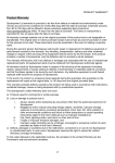
This page is intentionally left blank
INDEX
Technical features
page 3
DMX signal and audio connection
page 4
Ex. Connection spots/controller
page 4
1 - Description of commands
page 6
2 - Fast Operation on the Control 5
page 7
How to select a program.
How to select a scene
How to program the spots functions
How to play a program
3 - Basic Operations
page 9
Programs
Spot functions (single, all , none, spot groups)
4 - Making the scenes
page 10
Insert a new step
Edit a step
Global time and step time
Wait time and fade time
5 - Programming the fixtures into the scenes
page 13
How to modify the value of the spot functions
Axis inversion
6 - Shapes
page 14
Shape starting point
How to insert a Shape
How to run a Shape
7 - Additional programming functions
page 15
Delete a step
Copy a step
Copy a program
Delete a program
8 - Running the Programs
page 17
Auto mode
Manual mode
Music mode
Black Out mode
9 - Configuration menu
page 18
DMX in and MIDI
USB light
Beep
How to make a new patch
How to make a custom fixture
Lock function
10 - Errors messages
page 22
11 - Test function
page 24
1
TECHNICAL FEATURES
- Full 512 DMX Channels
- Store up to 4000 Scenes
- The scenes can be stored in 100 different programs
- Up to 40 fixtures can be controlled and five groups of fixtures are available
- 32 DMX channels for each fixture
- Each parameter has 8/16 bit resolution
- 16 faders for manual control
- The controller can be synchronized with an external device by MIDI IN, DMX IN or MUSIC IN
- An Incremental cloche is available for precision moving head positioning, with associated two
buttons to invert each axis (x – inversion, y – inversion)
- Internal preset are available to create several automatic shapes in very short time
- Each internal preset can be edited and stored in user memory
- Direct access to main functions by individually buttons
- Advanced functions are available by three buttons with dynamical menus
- For every scene are available two timers(WAIT TIME and FADE TIME) to create the fades from
a scene to the next one
- An immediate numeric keyboards is used to fast recall programs, steps or assign a numeric value
to a parameter (Ex. If you have a 16 BIT parameter on a slider, you can assign a precision 16 BIT
value by the numeric keyboard)
- Flash buttons can be used in a dimmer patch or to assign a specific function to the parameter
- Firmware upload via DMX line
- USB connector for DJ work light
- Power failure memory
- Power input DC 12.24V, 500Ma MIN.
- Power supply included
- Rack mount – 4 Rack spaces
- Dimensions: 530x220x100 (WxDxH)
- Weight: 3.5 Kg
- 120 and 230V operation available
2
DMX signal connection
EXAMPLE of connection DMX controller-spot
3
4
1 - Description of commands
BUTTONS:
0/9
= Numerical buttons for values setting.
PROG
= Select a program.
STEP/. = On the introduction of several numerical parameter, allow to insert the decimal dot.
ESC
= To exit.
ENTER = To confirm.
X/Y INV = To invert axis x/y on the joystick referring to the selected spots.
SHAPES = to enable or disable the preset shapes on selected spots..
MENU/F1, F2, F3 = keys for dynamic menus. Press button MENU/F1 from main screen, to enter in the
configuration menus of the controller.
AUTO
= to select the automatic scrolling of the scenes
MAN
= to select the manual scrolling of the scenes.
MUSIC = to select the scrolling of the scenes on music time.
-,+
= to set the manual mode of the scene, to change the general parameters into the menus.
COPY STEP
= to copy a scene..
DEL STEP
= to delete a scene.
COPY PROG
= to copy a program.
DEL PROG
= to cancel a program.
INS STEP
= to insert a scene in the program or to edit a scene..
SPOT 1-20/21-40 = to select the spots from 1 to 20 or from 21 to 40..
1-20
= To enable the buttons SPOT from 1 to 20.
21-40
= To enable the buttons SPOT from 21 to 40.
NONE
= to disable all spots.
ALL
= to select all the spots.
SINGLE = To change the selection of the spots.
IN SINGLE OFF mode: buttons SPOT1-20/21-40 selects and deselects the corresponding spot
at every pressing, so it is possible to select more items.
In SINGLE ON mode, the selection of one spot allows the deselection of the previous selected,
so it is possible to select one item at time.
SPOT GROUPS 1-5
= to recall five groups of spots
CH PAGE
= to change alternatively the pages of DMX Channels (1–16 or 17–32)
FLASH 1-16/17-32
= to set DMX channel at 100%, when the controller is in Dimmer mode, to enable the
channel for introducing data by keypad.
5
2 - FAST OPERATION ON THE CONTROL 5
To operate the Control 5 immediately, follow the instructions indicated in the sections:
- Patch
- Basic Programming
- Play
To learn all the other functions of the Control 5 controller, it is necessary to read the whole manual carefully.
PATCH:
-
-
In the controller there is a default patch, if the default patch satisfies the requirements of the operator
it is possible to proceed to assign to each spot the right DMX address. If it is necessary modify the
patch, go to the paragraph CONFIGURATION MENU, make a new Patch and come back to this
point.:
In order to assign the right DMX address to each spot, select the spot on the controller and read on
the display the starting DMX value:
BASIC PROGRAMMING:
1) How to select a program:
- The first time you switch on the controller the display will show:
Press SPOT or
PROGRAM to start
- Press PROG button to select one program.
- On the display, the following menu will be shown:
Digit the required program number and press OK (F1) or ENTER. To cancel the last digit number press F2.
To decrease the value press – to increase press +.
To leave the function press EXIT (F3) or ESC.
If you select the program number 1, the display will show:
2) How to make a new scene:
-
Before start making a new scene, be sure to have selected the MANUAL function.
To make a new scene, press INS STEP. Being the program empty, the following menu will be shown
on the display
You can set up the new program on Global Time or Step Time. Press EXIT (F3) or ESC to go back to the
options without any change.
a) In Global Time all scenes will have same life-time but a different time of fading can be assigned to each
single scene.
6
The fading time can be lower or equal than the global time of the scenes. In case it is lower, at the end the
scene, the spots remain in stand-by until the end of the global time and the change of the new scene.
b) Step Time, every scene has its own fading time and its own stand-by time, freely arranged.
At the end of fading (after the evolution of the parameters), the scene remains in stand-by for all the
remaining time up to the change of the scene.
Both in Global Time or in Step Time, you can enter the values moving the two sliders WAIT TIME and FADE
TIME.
- Once you have moved the slider, you can also set the right value through the buttons 0-9.
Once fixed the times of the scenes, you are ready to start programming, the display will show:
(in this case it has been selected a global time of 1 sec.)
3) How to start programming the spots functions:
-
Select through the spot buttons, the fixture/s you want to program.
Every time you select a spot, and you start to move a slider, on the display will be shown the function
pertinent to that slider and the DMX value.
- The DMX value can be assigned or through the slider or by the 0-9 buttons.
- Once you have programmed all the fixtures for the first scene press ENTER button to save the
scene.
- Use the INS STEP button to input a new scene in the current program, or to edit again the current
scene.
If the current program is t empty, digit this button and the controller will show the following menu:
At this point you can decide to add a new scene at the end of the current program (ADD), or to input the new
scene at the same position of the current scene(INS), moving the others scenes forward, or to edit the
current scene.
- Once you have finished to program all the scenes, you are ready, to run your program.
- Play
- Use the buttons AUTO, MAN and MUSIC to select the three different ways of scrolling the
scenes (sequentially, manually or on music time)
- Operating on the SPEED slider you can increase or decrease (+ or – 400%) the speed already
stored in each scenes.
7
3 – BASIC OPERATIONS
PROGRAMS:
- Press PROG button to select a program..
- The following menu will be shown:
- Using the 0-9 buttons, digit the required program number and press OK (F1) or ENTER. To cancel the last
digit number press F2. To decrease the value press – to increase press +, to leave the function press EXIT
(F3) or ESC.
- 100 programs are available, all numbered from 1 to 100. If 0 or a number bigger than 100 is
settled the error message ‘WARNING! OUT OF RANGE’ will be shown, and if you forget to
digit the number before pressing OK (F1) or ENTER the display shows the error message
WARNING. MISSING VALUE.
SPOTS:
- Control Five can drive up to 40 spots, numbered from 1 to 40.
- There are different ways to select the spots:
1) SINGLE button
- When LED is off (function SINGLE disconnected) pressing SPOT 1-20/21-40 allows the
selection and deselection of the corresponding spot. In this way it is possible to select more than
one spot togheter.
- Pressing two buttons SPOT 1-20/21-40, at the same time, all the fixtures included between them
will be selected. Ex: pressing SPOT 1 and SPOT 8 (at the same time) you can select fixtures
1,2,3,4,5,6,7,8 in one shot.
- When LED is on (function SINGLE working) pressing SPOT 1-20/21-40 allows the selection of
the corresponding spot and the deselection of the previous one. In this way the spot can be only
selected one-by-one.
The button SPOT 1-20/21-40 allows to select alternatively all the spots 1-20 and 21-40.
2) ALL button
- The ALL button will selects all spots.
3) NONE button
- The NONE button will deselects all spots
4) SPOT GROUPS buttons
- The SPOT GROUP buttons (1-5 ) will recall five groups of spots.
To memorize a group of spots, operate as following:
- Select the required spots through the SPOT 1-20/21-40 buttons and then press one of the 5 buttons
SPOT GROUPS 1-5,
- press the above button for more than 1 second,
- When all the LEDs of the buttons SPOT start to flash, leave the button SPOT GROUPS.
- w the group of spots is memorized on that button and, pressing it, the user will call those spots
anytime.
8
4 - MAKING THE SCENES
When a program is empty, the display will show:
To make a new scene, press INS STEP. Being the program empty the follow menu will be visualized:
You can set up the new program on Global Time or Step Time. Press EXIT (F3) or ESC to back without any
change.
In Global Time all scenes have same life-time but a different time of fading can be assigned to the scene, in
this time the parameters change up to the needed value.
The fading time can be lower or equal than the global time of the scenes. In case it is lower, at the end the
scene remains in stand-by until the end of the global time up to the change of the scene..
In Step Time, every scene has its own fading time and its own stand-by time, freely arranged.
At the end of fading (after the evolution of the parameters), the scene remain in stand-by for all the wait time
up to the change of the scene.
a) Pressing GLTM (F1) the menu will show:
The program is setted in Global Time, default time is 1.0 sec for global time and fading time.
Global time can be settled from 0.1 to 120.0 sec through the slider WAIT TIME, meanwhile the fading can be
settled from CUT (0), up to the same value of the Global time using the slider FADE TIME.
(Once moved one of the two slider you can enter the right time using the 0-9 buttons).
- Press SAVE (F1) to save the new scene, press EXIT (F3) or ESC to leave the function.
b) Pressing STTM (F2) the controller will show:
The program is setted in STEP TIME with time default of 1.0 sec for both waiting and fading time
Both times can be settled from CUT (0) up to 120.0 sec. Waiting time can be settled through the slider WAIT
TIME meanwhile fading through the slider FADE TIME.
Setting CUT both for waiting and fading time, the controller takes a minimum time of 0.1 sec
(Once moved one of the two slider you can enter the right time using the 0-9 buttons).
- Press SAVE (F1) to save the scene, press EXIT (F3) or ESC to leave the function.
After the first scene, the controller will show:
If you desire to program the spots in the first step, please read carefully the paragraph n. 4.
If on ather hand you prefer to add more steps in the program number 1, repeat the same operations reported
in the current page.
9
At this point, for instance the display will show:
(it means that you will have made 9 scenes totally, and you are in the number 9 of the program number 1).
To change the current scene you can use -,+ buttons (in manual mode) or use STEP/.. button if you want to
jump some steps.
- Pressing the STEP/. Key and then the 4 button, the display will show for instance:
- To confirm press OK (F1), to leave the function press EXIT (F3) or ESC.
If you input the number 0 or a number greater than the number of the scenes in memory the controller will
shows: ‘WARNING Out of Range’.
Pressing OK or ENTER without input the number of the scene the error message ‘WARNING Missing Value’
will be shown.
-
Pressing the INS STEP button you can input a new scene in the current program, or you can edit the
current scene, the display will show:
At this point you can decide to add a new scene at the end of the current program, or input the new scene at
the same position of the current scene, moving the others scenes forward, or to edit the current scene.
1) Pressing ADD (F1) the new step will be added at the end of existing steps and the controller will show one
of these menus:
if current program is in Global Time:
If current program is in Step Time:
In Global Time the field g.g holds the global time value of the current program, the fields w.w and f.f hold the
stand-by time and the fading time respectively, and without any change these ones will be copied in the new
scene.
To add the new scene to the program press SAVE (F1), to leave the function press EXIT (F3) or ESC.
2) Pressing INS (F2) from menu Insert/Edit Step the function is similar, except that the new scene will be
inserted in the actual position shifting all the remaining steps of one position.
3) If you whish to modify one of the existing step, from the menu insert/Edit Step press EDIT (F3) and the
controller will show:
You can choose to re-set the current program in Global Time, or Step Time or you can edit time using the
current mode. To leave the function press ESC.
10
a) Pressing GLTM (F1) the controller will show:
In Global Time:
In step time:
In the first situation you can see the current value of global time and fading time, meanwhile in the second
situation you can see the default time of 1.0 sec.
To save the scene press SAVE (F1), to leave the function press EXIT (F3) or ESC.
b) Pressing From menu Edit Step STTM (F2) you will see one of these menus:
In Step Time:
If the current program is in Global time you have to re-set it in Step Time:
In the first situation you will see the current values of waiting and fading time, in the second situation you will
see the default time of 1.0 sec.
To save the scene press SAVE (F1) to leave the function press EXIT (F3) or ESC.
From menu Edit Step press NEXT (F3) the controller will show:
In Global Time:
In Step Time:
In Global Time the field hold the value of global time in the current program, and the fields w.w and f.f hold
waiting and fading time of the current scene respectively.
To save the scene press SAVE (F1) to leave the function press EXIT (F3) or ESC.
All the time global stand-by and fading can be settled by slider WAIT TIME and FADE TIME or using the
keypad. The function is the same of the one for the input of the value of channels.
For ex. You can modify the fading time of one scene using the slider FADE TIME, then you can digit a
numeric value and the controller will show:
The value you have input is 12, at the end of the input press OK (F1) or ENTER.
To cancel the last number press Å (F2). To leave the function press EXIT (F3) or ESC.
Use key STEP/. button to input decimal point.
Press ENTER to save the current scene. The message Step Saved will confirm the rescue.
11
5 - Programming the fixtures into the scenes:
The controller can drive a maximum of 40 fixtures, each one up to 32 DMX channels.
HOW TO CHANGE DMX VALUE TO EACH PARAMETERS:
Once you have selected a spot/spots or group of spots (as reported page 7), proceed in the following way:
- To modify the numeric value of each DMX channels use the sliders CHANNELS 1..16/17..32.
- Use the button CH PAGE to select the page of the channels that you want to attend.
- Pressing this key the sliders will attend alternatively on channel 1..16 and 17..32, in order to kw in
which page you are, the channel 1 or 17 will be shown on the display.
- The value of each channel can be changed operating on the slider or inserting a new value
using the 0-9 buttons..
After modifying the value of the channel using the relative slider, the display of the controller will show for
instance:
- In this example you are programming the spot 1 (that is a Shark 159, with DMX address 001) and you have
moved the Color channel for which you have assigned a value of 50.
- When moving the slider of one parameter, you can also set the right value through the 0-9 buttons, in this
case the display will show:
- Press OK (F1) or ENTER.
- To cancel the last number press Å (F2). To esc press EXIT (F3) or ESC.. In case you digit a
number higher than 255 the error message WARNING OUT OF RANGE will be shown, and if
you forget to put the value of the channel before pressing OK (F1) or ENTER the error message
WARNING. MISSING VALUE will be shown.
- To modify the PAN/TILT position you can use the joystick or the sliders CHANNEL 1..16/17..32 referred
to the pan and tilt parameters.
AXIS INVERSION:
You can change the movements of the two axis of the joystick with the X INVERTION and Y INVERTION
buttons...
- Pressing this button all the four available combinations for X and Y will be selected sequentially.
For instance, if you select the spot number 1 and it is a Shark 150W assigned at DMX 001 channel. and Pan
and tilt are both at middle coarse, with a DMX value of 32768 ( for spots with resolution at 16 bit), the display
will show:
In this case, the pan parameter is inverted meanwhile the tilt is direct, showed by mark – after P and by mark
+ after T .
The possible settings are:
1) P+32768 ---T+32768
2) P-32768 ---T+32768
3) P+32768 ---T-32768
4) P-32768 ---T-32768
These settings are valid for all the selected items (spot7spots or group of spots), if not items are selected the
message WARNING not active spots will appears.
12
6 - SHAPES
The controller allows to assign to Pan and Tilt parameter 4 moving shapes already stored in the Control 5.
It is also possible to fix a different Shape starting point for each single fixture. (only one starting point can be
memorize for each fixture and it will be the same for any scenes)
How to memorize the starting point:
When the display is on the Menu window, press F2 (CNFG), on the display will appear:
Press F3 (NEXT), on the display will appear:
Press F2 (SHPS), on the display will appear:
Select the desired spot/spots and fix the Pan/Tilt position using the Joystick.
Repeat the same operation for the remaining spot/spots. (for each spot can be assigned a different Shape
start position, but only one)
When all the positions are programmed press F1 (OK), on the display, for 1 second, will appear:
The Shape starting position are now saved and can be recalled in each scene.
-
How to assign to a spot, one of the 4 prestored Shapes, meanwhile you are programming a scene:
1) Using the 1-20/21/40 buttons, select the spot/spots on which you want to apply the on board
Shapes.
2) Press the key SHAPES to apply the shapes on the selected items. To unable them, press again
SHAPES.
For ex. When you apply a shapes on item n° 1, the display will show:
(sh after Sp01 means that a shape has been selected for that fixture in that step)
Using the slider Channels 1..16/17..32 referred to Pan and Tilt parameter (in this case for the Shark 150, 5 –
6 – 7 – 8) you will be able to change the Shape functions as follow:
-
Pan Coarse – (channel number 5 in our case) > Shape
This parameter, is divided into 4 equal parts 0-63, 64-127, 128-191, 192-255, allows to select one of
the 4 on board shapes.
-
Pan Fine – (channel number 6 in our case) > Shape Speed
This parameter modifies the speed performance of the selected shape.
-
Tilt Coarse – (channel number 7 in our case) > X-Size
This parameter modifies the amplitude of the excursion referred to the Pan movement.
-
Tilt Fine – (channel number 8 in our case) > Y-Size
This parameter modifies the amplitude of the excursion referred to the Tilt movement.
13
If you wish to add the Shapes to other spots, select other spot/spots and repeat the same operations.
In case you deal the key SHAPES when not items are selected the message WARNING NOT ACTIVE
SPOTS will appears, and if the spots can not work with the shapes, having not the parameter pan and tilt
16BIT, the display points out the message WARNING. NOT SHAPE MODE.
All shape data and scene parameters are saved on memory.
7 – ADDITIONAL PROGRAMMING FUNCTIONS
DEL STEP function:
Press DEL STEP to cancel the current scene moving all the next scenes down.
The controller will show the request:
Press YES (F1) or ENTER to cancel the scene, press NO (F3) or ESC to leave the function without
canceling the scene.
COPY STEP function:
To copy a scene press COPY STEP.
The following menu will appear:
You have 3 options:
a) You can decide to copy from another scene in the current one
b) You can decide to copy the current scene in another one.
c) You can decide to copy the Shapes starting position
a) Pressing FROM (F1), the following menu will appear:
The controller requests to digit the number of the original program from which you want to copy the scene.
Digit the number and press OK(F1) or ENTER.
At this point the following menu will appear:
The controller requests the number of the original scene that you want to copy.
Digit the number of the scene and press OK (F1) or ENTER.
NOTE: if the original program hold only one scene the menu From Step can not be visualized and the
controller will pass directly to the next operation.
If the program is empty the original scene will be the only scene of the program and the function will end,
otherwise the controller will show the following menu:
14
-
Press ADD to add the original scene at the end of the program.
Press INS to input the original scene to the place of the current scene moving forward the others
scene.
- Press COPY to replace the current scene with the original one.
Press ESC to leave the function.
b) Press TO (F2) from menu Copy Step to open the following menu:
The controller requests the number of the destination program in which you want to copy the current scene.
Digit the number and press Ok (F1) or ENTER.
NOTE: if the program is empty the message ‘WARNING! Empty Program’ will appears and the menu To
prog can not be visualized. At this point if the desired program is empty the current scene will replace the
only scene of the program and the function will end. Otherwise the controller will show the following menu:
-
Press ADD (F1) to add the current scene at the end of the desired program.
Press INS (F2) to input the scene before the scene you have previously digit, moving the next
scenes.
- Press COPY (F3) to replace the scene previously chosen with the current one.
Press ESC to leave the function.
d) Press FRSH (F3) to copy the Shapes starting position in the current step.
DEL STEP function:
To cancel all the scenes of the current program press DEL PROG.
The controller will request a confirmation:
Press YES (F1) or Enter to cancel all the steps of the current program, press NO (F3) or ESC to leave the
function without canceling the program.
COPY PROG function
To copy a program press COPY PROG
The following menu will be shown:
You can to decide to copy from another program in the current one or to copy the current program in another
one. Press EXIT (F3) or ESC to leave the function.
a) Pressing FROM (F1) the following menu will be shown:
The controller requests the number of the original program from which you want to copy all the scenes.
Digit the number of the program and press OK (F1) or ENTER.
NOTE: it is not possible for a program to copy itself so if you digit the number of the current program the
message ‘WARNING! Same Program’ will be shown.
15
At this point, if the current program is empty, the original program will be copied in the current program and
the function will end, otherwise the following menu will appears:
-
Press JOIN (F1) to add the original program at the end of the current program.
Press INS (F2) to input the new program in the position of the current scene, moving forward all the
others scene.
Press COPY (F3) to replace the current program with the original one.
Press ESC to leave the function.
b) Pressing TO (F2) form the menu COPY PROGRAM the following menu will be shown:
The controller requests the number of the destination program in which you want to copy all the scenes of
the current program.
Digit the number of the program and press OK (F1) or ENTER.
NOTE: in case the program is empty the error message ‘WARNING! Empty Program’ will be shown
NOTE: it is not possible for a program to copy itself so if you digit the number of the current program the
message ‘WARNING! Same Program’ will be shown.
At this point, if the destination program is empty, the current program will be copied in the destination one
and the function will end. Otherwise the following menu will appears:
-
Press JOIN (F1) to add the current program at the end of the destination program.
Press INS (F2) to input it in the position of the scene previously chosen, moving forward all the
others scenes.
Press COPY (F3) to replace the desired program with the current one. Press ESC to leave the
function.
If the destination program holds more than one scenes, pressing INS (F2) the following menu will be shown:
You have to digit the number of the scene of the destination program before which you have to input the
current program.
After every operation on scenes and programs Control Five shows the number of the available scenes.
Switching on the controller you can visualize this information.
8 - RUNNING THE PROGRAMS
Use the keys AUTO, MAN and MUSIC to select the three different ways to run a program (sequentially,
manual and musical).
- Using the AUTO mode (sequential model), each scene can have an individual time or a global time (the
same for all the scenes in the program) according to the program made.
- Using the MAN mode, you can change the scenes manually.
16
- Using the MUSIC mode, the scenes can work in auto mode following a musical signal presents on the jack
input in the rear of the controller.
When in the music mode, pressing the +/- buttons you can modify the electrical level of the music signal.
MANUAL/AUTO Function:
While the controller works in auto or musical mode, it is possible to modify manually the parameters of one or
more fixtures.
- To use this function select the spots you want mode manually.
- You can now change manually all the parameters to the chosen spots.
- During this operation the spots not selected will continue to run in auto mode.
- To leave the function deselect all the spots with the NONE button.
NOTE: the controller memorize two different pages of the selected spots, depending to the manual or
automatic functioning.
Pressing AUTO or MUSIC the spots selected, the ones of the first page, will be deselected and they can be
selected again pressing MAN. In this way you can avoid that passing in automatic mode the selected spots
will not consider the manual commands and will not follow the sequence of the scenes of the program..
During the automatic function the spots selected by manual mode will found the second page, and backing
to the manual mode, these spots will be substituted with the spots of the first page.
BLACK-OUT Function:
Meanwhile running a program in AUTO, MANUAL or MUSIC mode, it is possible to insert the black out
function on all the fixtures just pressing the F3 key, located below the display; all the leds will start to blink
untill you press again the F3 key and leave the black out function.
9 – CONFIGURURATION MENU
Press the ESC button to enter in the configuration of the CONTROL FIVE, the display will show the
following menu:
- Press MODE (F3) to input the Dimmer function to the sliders CHANNELS 1..16/17..32.
a) In Editor mode the sliders will work in increasing way, so that if you raise one slider the value of the
parameter will increase, meanwhile turning down it will decrease.
The position of the slider and the value of the corresponding parameter can be equal or not:
- when not equal, the red led is on.
- When they are equal the green led is on.
b) In Dimmer mode the sliders assign the value of the corresponding parameters. This function can be used
only when the controller is a dimmer box, in fact you can not edit a scene in dimmer mode without loosing
the original value of the parameters, taking the ones of the sliders. In dimmer mode the slider MASTER
modifies the intensity of the channels and the FLASH 1..16/17..32 button set the corresponding parameter at
100%.
UTILITY functions:
Pressing the UTIL (F1) button allows to enter the utility menus:
a) Pressing DMXI (F1) is possible to assign a starting DMX IN channel to be used to drive the controller
from another DMX-512 console, the following menu will appear:
17
Digit the number of the channel you desire and press OK (F1) or ENTER.
The controller can be driven through four DMX channels:
1 – mode
2 – program
3 – scene (high part)
4 – scene (low part)
- Channel 1 (MODE), from 0 to 127 set the controller in manual mode, as per MAN button. From 128 to 255
set the controller in automatic mode, as per AUTO button.
- Channel 2 to change the program, as per PROG button.
- Channel 3 and 4 to change the scene, as per STEP/.. button.
Example 1:
1 – mode
2 – program
3 – scene (high part)
4 – scene ( low part)
=0
=10
=1
=12
The user intends to call the scene 268 (1*256+12) for program 10.
Example 2:
1 – mode
2 – program
3 – scene (high part)
4 – scene ( low part)
=255
=1
=0
=0
The user intend to call the program 1 in automatic mode.
b) Press MIDI button (F2) to enter the channel midi to be used to drive the Control 5 from any midi device,
the display will show:
Digit the number of the Midi channel and press OK (F1) or ENTER. To cancel the last digit number press Å
(F2). To increase the value press + to decrease press -. To leave function press EXIT (F3) or ESC.
In case you digit 0 or a number bigger than 16 the error message ‘WARNING! Out of Range! Will appear.
Pressing OK (F1) or ENTER without input the number of the channel the message ‘WARNING! Missing
Value’ will appear.
This function allows to synchronize two or more controllers so to increase the number of the DMX channels,
and also it allows to control the controller by a sequencer midi or a PC program:
How to select a program on the Midi device
<PROGRAM CHANGE>
<program number>: program (0..99)
To select a scene:
<NOTE ON>
<key>
: scene (high part)
<velocity>
: scene (low part)
18
c) Pressing the NEXT (F3) button allows to pass to the second menu, the display will show:
a) Press LGHT (F1) button to set the brightness of the lamp connected to USB socket.
Digit the value of brightness and press OK (F1) or ENTER.
The setting-out is saved on not volatile memory.
b) Press BEEP (F2) button to able or disable the buzzer inside the controller.
The display will shown:
- To disable the buzzer press OFF (F1).
- To enable the buzzer press ON (F2).
To leave the function press EXIT (F3) or ESC.
HOW TO MAKE A PATCH:
When on the following main menu:
Press the CNFG (F2) button to enter the configuration menus:
a) Pressing PTCH (F1) to set the patch, the display will show:
Press EXIT (F3) or ESC to leave the function.
To set a new patch read the following the instructions:
1)
2)
3)
4)
Using the SPOT keys, select the spot/spots or a group of spots to assign to a model
Select the model by +/- buttons (a library of spot models is available)
Repeat the same operation for other spots to assign to a different model
Press OK (F1) or ENTER
Setting a new patch implies the formatting of the memory, so the controller will show the following request:
Press YES (F1) button or ENTER to confirm the setting of the patch and the formatting of the memory, press
NO (F3) or ESC button to leave the function without any change.
19
If you press YES (F1) button the controller will show the following request:
Pressing YES (F1) button you delete all the memory and the controller will show:
Pressing NO (F3) button you will create a new patch without clean your work (programs and steps so far
made) and the controller will show the main menu page
In case the number of the DMX channels of the new patch is bigger than 512 the error message ‘WARNING!
No DMX512 Space!
b) The CSTM (F2) button from Configuration menu allows to create 8 custom models.
This function is useful in case you don’t find the desired model in the memory of the controller
The following menu can be visualized:
-
To increase the number of the custom model to edit press + , to decrease press -.
When decided the number of the custom you want to edit, Press EDIT (F1) or ENTER , to leave the
function press EXIT (F3) or ESC.
The display will show:
In this default case, the model has 32 parameters and the first one is the Dimmer
- To modify the total number of the parameters press CN-1 (F2) or CN+1 (F3).
- To change the function to the Ch01 use the -/+ buttons
- To edit the second channel press the FLASH button2 and use the -/+ buttons to assign the desired
function.
- Repeat the same operation for each one of the total channels.
- When finished, press OK (F1) or ENTER to confirm the operation, press ESC to leave the
function.
After pressing OK or ENTER the controller may ask you a confirmation:
Press YES (F1) to confirm the settled of the custom model, press NO (F3) or ESC to leave the function
without any change.
At this point the controller check if there are some parameters repeated or if the PAN/TILT Coarse-Fine are
in the right position. If there are some errors the following message will appears:
‘WARNING! REPEATED PARAMS’ (with parameters repeated)
‘WARNING! Not FN after CR’ (pan/tilt coarse is not followed by pan/tilt fine)
‘WARNING! Not CR before FN’ (pan/tilt fine is not anticipate by pan/tilt coarse)
20
NOTE: It is not possible to edit a custom model already settled in the patch, because any change will cause
malfunction with the programs already memorized , when the user press EDIT (F1) or ENTER a check will
be done to verify if the selected model is already settled in the patch.
If yes, the error message ‘WARNING! Model On Patch’ will be shown
Without errors the custom model is settled and the function ends.
LOCK function:
When on the following main menu:
Press CNFG and the display will show:
Press NEXT (F3) and the following menu will appear:
Pressing the LOCK (F1) button it will enable and disable the protection of the memory.
The controller has a protection in order to avoid any kind of input by not-authorized users.
The following message will be shown:
To modify the protection digit the code number 2-6-4-5
Pressing ESC to leave the function.
10 – ERROR MESSAGES
The controller shows an error message when the user press a wrong button, after an incorrect operation or
after a functional defect.
List of Error Messages:
The controller is out of memory, there is not space to save other scenes.
The function can be activated in manual mode only. For example: STEP/ button.
21
When the user try to change scenes or programs with locked memory.
The function can not be activated because the current program is empty. For example: COPY PROG-TO
button.
The function can not be activated because the programs are empty: for example: COPY PROG button.
When the user try to copy a program on itself.
A value out of range. For example: Program 101
The user digit OK (F1) or ENTER without input a value
Pressing SHAPES button not spots can work with the selected shape.
The function can not be activated because the spots have not been selected. For example: X/Y INV button.
When the user try to select a patch in which the total of the parameters of the spots is bigger that 512.
The controller has found inconsistency on data of memory, caused by problems of power supply.
22
When the user try to edit a custom model that is already settled in the patch. This operation is not allowed
because every changes will cause problems at the programs already created.
The user is trying to realize a custom model in which the parameter is repeated several times.
When the user try to realize a custom model in which the parameter Pan/Tilt Coarse is not followed by
Pan/Tilt fine.
When the user try to realize a custom model in which the parameter Pan/Tilt Fine is not came first Pan/Tilt
coarse.
11 - TEST FUNCTIONS
Control Five has some functions that are not available during the utilization. These functions, needed for the
test of the system, can be recalled starting when switch on the controller pressing one button or a couple of
button between the ones listed here below:
0+F3 general starting
Input this function when the controller starts for the first time, with the not-volatile memory still empty. The
following operations will be done:
1) memory test
2) memory formatting
3) A/D converters test
4) Keypad test
When the controller starts for the first time a check on the memory not-volatile has be done, so it is not
necessary to press 0+F3 buttons.
If the memory is not formatted the following message is shown:
Press YES (F1) or ENTER to enter the operation above-mentioned, press No (F3) or ESC to start the
controller without the formatting of the memory.
In this last case the user could find errors on the functioning.
0+F1 formatting memory
Cancel all the scenes
23
1: converters A/D test
To decrease the channel press – to increase press +. Moving the referring parameters the value will
not Press ESC to exit from the procedure.
2: keypad test.
Press any buttons to visualize the corresponding hexadecimal code. Press ESC to exit form the
procedure.
3: memory test.
To test the not-volatile memory. At the end, without any errors, the procedure ends automatically, otherwise
the message ERROR will be shown, after the visualization of the memory address that has created the
error.
4: To see the numbers of the ignitions.
Press any button to exit from the procedure.
5: To see the initial, the version and the date of the last service.
Press any button to exit from the procedure.
6 To see the content of the not-volatile memory.
To decrease the address press -, to increase press +.
Pressing 1,2,3 e 4 the buttons +/- can be changed (to increase or decrease) as follow:
1:8
2:128
3:2048
4:32768
Press ESC to exit form the procedure
______________________________________________________________________________________
NOTE:
________________________________________________________________________
________________________________________________________________________
________________________________________________________________________
________________________________________________________________________
________________________________________________________________________
________________________________________________________________________
________________________________________________________________________
rel. 0107
StudioDue s.r.l.
Str. Poggino,100 – 01100 Viterbo (Italy) Tel. +39.0761.352520 Fax +39.0761.352653
24
Head Office: STUDIO DUE s.r.l. (I)
Str. Poggino, 100 - 01100 Viterbo (Italy)
tel. +39.0761.352520
fax +39.0761.352653
[email protected]
STUDIO DUE (UK)
3 Encon Court Owl Close
Moulton Park Industrial Estate
Northampton England UK - NN3 6 HZ
tel. +44.1933.650.820
[email protected]
STUDIO DUE Far East LTD (HK)
Unit 8, 4/F, Harbour Centre Tower II,
8 Hok Cheung Street,
Hunghom, Kowloon Hong Kong.
tel. +852.29542141 fax +852.23302515
[email protected]
STUDIO DUE lighting technology (PRC)
Shen Zhen LTD (China)
www.studiodue.com
for technical info
[email protected]
Studio Due - ©
The features on this brochure are not binding: they can be changed without notice.
Le caratteristiche riportate su questo catalogo non sono impegnative: possono essere soggette a variazioni senza preavviso.