1
Author
Øystein Krag
Approved
Roar Jakobsen
Company
Page
4tech AS
1(16)
Document no.
Revision
15-CMC09006
Title
B
Date
2009.03.17
File
MiniCom Guardian User Manual
c
MiniComGuardian_UserManual_VersionB.do
MiniCom Guardian
User Manual
1 Contents
1
2
3
4
5
6
7
8
Contents ........................................................................................................................................................................... 1
Revision History ................................................................................................................................................................ 2
What does my Guardian do? ............................................................................................................................................ 2
Installation......................................................................................................................................................................... 2
4.1
Preparations .................................................................................................................................................................. 2
4.1.1
Get a SIM card ....................................................................................................................................................... 2
4.1.2
Prepare power supply ............................................................................................................................................. 2
4.1.3
Plan location for sensor and MiniCom .................................................................................................................... 2
4.1.4
Determine alarm limits ............................................................................................................................................ 2
4.2
Physical installation ....................................................................................................................................................... 3
4.3
Enter PIN code .............................................................................................................................................................. 3
4.4
Set date and time .......................................................................................................................................................... 3
4.5
Configure id and alarm limits ......................................................................................................................................... 4
4.6
Subscribe for notifications ............................................................................................................................................. 4
Getting information............................................................................................................................................................ 5
5.1
Checking status information (INFO)............................................................................................................................... 5
5.1.1
Sending SMS ......................................................................................................................................................... 5
5.1.2
Pressing button for 5 seconds ................................................................................................................................ 5
5.2
Getting current configuration (config) ............................................................................................................................. 5
5.3
Analysing detailed status (STATUS).............................................................................................................................. 5
5.4
Alarm behaviour and notifications .................................................................................................................................. 5
5.4.1
Value limit exceeded .............................................................................................................................................. 5
5.4.2
Power and battery alarms ....................................................................................................................................... 5
5.4.3
Battery change reminder (CHANGEBATT) ............................................................................................................. 6
5.4.4
Battery test ............................................................................................................................................................. 6
5.4.5
System alarms ....................................................................................................................................................... 6
Command interface........................................................................................................................................................... 6
6.1
General format .............................................................................................................................................................. 6
6.1.1
Behaviour ............................................................................................................................................................... 6
6.1.2
Syntax .................................................................................................................................................................... 6
6.1.3
Types ..................................................................................................................................................................... 7
6.1.4
Acknowledge .......................................................................................................................................................... 7
6.2
Configuration commands ............................................................................................................................................... 8
6.2.1
Overview ................................................................................................................................................................ 8
6.2.2
All commands......................................................................................................................................................... 9
6.2.3
STATUS ............................................................................................................................................................... 12
6.2.4
CONFIG ............................................................................................................................................................... 13
6.2.5
INFO .................................................................................................................................................................... 14
Events and alarms .......................................................................................................................................................... 15
Technical specifications .................................................................................................................................................. 16
Made in Norway
Copyright 2009 4tech AS
All rights reserved 4tech AS
www.4tech.no
Title
Revision
MiniCom Guardian – User Manual
A
Page
2(16)
2 Revision History
Date
Version
2009.02.18 A
Signature
ØK
Description
Initial version.
3 What does my Guardian do?
Congratulations with you MiniCom Guardian. Once the Guardian is installed with a SIM card, a Guardian sensor, and a power
supply, you will be able to:
•
Monitor external power supply
•
Monitor environment temperature
•
Monitor relative humidity
•
Easily get current status on SMS
•
Perform all configuration using SMS
•
Get alarm notifications on SMS with status when monitored values cross given limits
E.g. “Temperature is too high”
•
Get notification when an alarm is reset
E.g. “Main power OK.”
•
Register up to 4 notification recipients
The backup battery and GSM module makes sure you will always get the relevant notifications from the Guardian, and the
system does not rely upon any other infrastructure than the GSM network.
4 Installation
Before you begin, you must make sure you have a valid SIM card to use with the MiniCom Guardian. You must also make sure
the GSM coverage is good enough (at least two points of coverage on your mobile phone, using the same operator). If the
coverage is not good enough, it is possible to connect an external antenna and to try different locations in order to retrive the
best signal.
NOTE: We recommend getting a SIM card with a special “alarm” or “data only” subscription. These subscriptions are cheeper
and no not support speech. This way, the SIM card is less likely to be a subject for unauthorised use.
Please make sure that you connect the power supply to the power you want to be monitored. If a UPS is involved, you should
make sure the power is connected to the same source as the UPS, so you get an early warning if the main power fails before
the UPS runs out of battery.
Plan the location where you want the sensor and MiniCom to be installed, and make sure you have the correct cable lengths. If
longer sensor cables are required, you can use a regular patch cable with RJ45 connectors (maximum 20 meters).
Consult with the recommendations for the preferable temperature and humidity ranges in the environment to be monitored.
Page 2 of 16
Title
Revision
MiniCom Guardian – User Manual
A
Page
3(16)
Install the Guardian control unit in a dry indoor environment.
1. Remove the front cover, and insert the SIM card into your Guardian control
unit (located in the battery compartment).
2. Make sure the SIM-lid is properly mounted. (Slide forward and you should
hear a click.)
3. Mount the battery plug, and fit the battery into the slot.
4. Mount the DIN rail with screws or two folded tapes where you decide to
mount your Guardian.
5. Mount your Guardian control unit onto the DIN rail
6. Mount the sensor (the blue box) at the location to be monitored.
7. Attach the sensor to the Guardian control unit in the left hand socket by
using the blue CAT5 patch cable.
8. Connect the power supply to the right hand socket of the Guardian.
Important: Connect your Guardian to the same power outlet as your UPS
or server is connected to.
When the Guardian is started with a SIM-card for the first time,
and the PIN code is enabled, it will ask for a PIN code with a
sequence of audio signals (PIN code is only requested for the
first start up).
•
Enter the PIN code using the red button. Each digit is entered by pressing
the button the corresponding number of times (1= 1 push, 5= 5 pushes and 0= 10 pushes). Each digit will be
repeated from Guardian before the next digit can be registered.
When all 4 digits are registered, you will hear an acknowledge signal, and the MiniCom will restart and attempt to use the new
PIN code. If the PIN code is accepted the MiniCom will again reboot, and start normal operation (GSM connection is indicated
by the yellow LED).
If the PIN code is wrong, the MiniCom will reboot and again ask for a new PIN code.
Please note: If you make a mistake, wait until you get the same sequence of signals (approximately 7 – 8 seconds) and start
again. Alternatively you can press the red button for approximately 3 seconds until the MiniCom Guardian stops beeping. Now
the MiniCom Guardian is ready for entering pin code again from beginning.
Please note: If you enter the wrong PIN code three times, and have to enter PUK code, we recommend inserting the SIM card
in your mobile phone to enter the PUK-code. It is off course also possible to enter the PUK code directly on the MiniCom
Guardian too.
If the system clock is set, you will be able to analyse the time and date of the latest 10 alarms. The MiniCom Guardian can be
set up to automatically update itself with the correct date and time. In order to do this, you have to register the MiniCom phone
number, so that the MiniCom Guardian is able to send SMS to itself.
Please send the following message (all commands are case insensitive):
PH=<phone number>
Example:
PH=99887766
Or international number:
PH=+4799887766
Page 3 of 16
Title
Revision
MiniCom Guardian – User Manual
Page
A
4(16)
The MiniCom Guardian will immediately send an SMS to itself and keep the internal clock updated. By default, the updating
process is repeated every month.
The MiniCom Guardian is configured using simple SMS commands. Several commands may be sent as one single SMS
separated by space (all commands are case insensitive).
Example:
ID=”Server room” MINTEMP=19 MAXTEMP=26.4 MINHUM=15 MAXHUM=57.5
This command sets the “name” of the Guardian to “Server room”, the minimum temperature limit to 19°C, the maximum
temperature limit to 26.4°C, the relative humidity minimum limit to 15% and the relative humidity maximum limit to 57.5%.
Please note that the ID requires double quotation marks (“ “) if the string includes spaces. Decimal separator is set by uning a
dot and not comma.
Send the configuration commands to the Guardian phone number as shown in the example (see section 6.2.4).
Send a SMS to the MiniCom Guardian with the message: config
The command results in the following response from Guardian:
Server room:
Temp: 23.8’C
(min:19 max:26.4)
Humidity: 42% (min:15 max:57.5)
No active alarms
followed by a second response from the MiniCom Guardian:
MID=<MiniCom ID> OK
The MiniCom ID is the serial number labelled at the back of your Guardian. The “OK” is an acknowledgement that the
commands have been accepted. If anything was erroneous, you will get the “ERROR” response as described in section
6.1.4.2.
The next section describes how to subscribe for alarm notifications.
!
!
Up to 4 phone numbers can be set up to subscribe for alarm notifications from MiniCom Guardian.
Each of the 4 numbers can be set using the PHN command (all commands are case insensitive).
Example, setting the number at position 3 (of 4) to the phone number, “12345678” (space only between the commands):
PHN=3,12345678
Example, setting an international number at position 1:
PHN=1,+4712345678
Page 4 of 16
Title
Revision
MiniCom Guardian – User Manual
A
Page
5(16)
5 Getting information
"
# $%&
Send INFO in a SMS to MiniCom Guardian, to get the current status information and a list of active alarms in a user friendly
format.
Please see the description of the INFO command for more details (See section 6.2.5)).
!
Press the button for 5 seconds until you hear a beep, to send and INFO report to all defined SMS subscribers
(Please see “Subscribe for notifications” in section 4.6).
'
#
&
See CONFIG in a SMS to MiniCom Guardian, to get current configuration. See section 6.2.4)
(
# )()* &
Send STATUS to get detailed status information including historic and active alarms. The difference between the STATUS
report and INFO report, is that the STATUS report is more compact and includes the last 10 alarms (historic and active) with
timestamp and duration. This can be useful for analysis after an alarm situation.
Please see the description of the INFO command for more details (see section 6.2.3).
(
!
+
When an alarm is triggered, the alarm is marked with a time stamp, and the associated notification message is sent to the
given SMS recipients (as described in section 4.6).
Typical notification message:
Main power missing.
Server room:
Temp: 23,8’C
(min:19 max:26)
Humidity: 42% (min:15 max:57)
Active alarms: NOPOWER
The system can trigger a number of different alarms divided into the following categories:
"
#
If a value exceeds a given limit, the associated alarm triggers immediately. The alarm is automatically reset when the value
resturns on the valid side of the limit, with a given margin (hysteresis). The default hysteresis values are 1 °C (HYSTEMP) and
5% (HYSHUM).
Example:
If the MAXTEMP limit is set to 30 °C, the MAXTEMP alarm triggers when the temperature exceeds 30 °C. If the temperature is
then lowered to 29.1 °C, the alarm is not reset, because the hysteresis (HYSTEMP) is set to 1 °C. When the temperature falls
to 29.0 °C, the alarm is reset.
!
A power loss (NOPOWER) is detected within shortest possible time (within 10 seconds). If you want the alarm to be triggered
after XX minutes, you must set PTIME=XX.
When the backup battery voltage runs below the required voltage, the GSMSHUT alarm notification is triggered, and the
modem is turned off. The MiniCom Guradian continues to run on battery for several hours more, to keep the alarm history and
Page 5 of 16
Title
Revision
MiniCom Guardian – User Manual
A
Page
6(16)
continue monitoring. When the main power returns, the battery must be charged for a few minutes before the GSM modem is
automatically turned on and the subscribers are notified with the recovery.
$
%
& '() *$(++,
Every 2 years, the backup battery should be replaced, in order to maintain the best quality. A CHANGEBATT alarm is then
triggered and notified by MiniCom, and the notification is then repeated every next 3 months.
Please note: MiniCom detects a battery change only if the main power remains on while changing the battery. This way you
will not turn off the MiniCom while changing battery and the alarm history is maintained in memory.
$
If you would like to test the backup battery capacity, you should do as follows:
•
Make a note of current time and unplug the MiniCom Guardian main power supply.
•
Wait for the MiniCom Guardian to send the alarm GSMSHUT (see section 7).
•
If the GSMSHUT alarm is not received within 60 minutes the battery is OK and the MiniCom Guardian main power
supply can be connected again.
•
If you receive the GSMSHUT alarm within 60 minutes, you should consider too order a new battery from 4tech.
The MiniCom guardian continuously monitors the internal hardware and reports any detected faults, so that action can be taken
If a system error occurs
6 Command interface
'
This section describes the standard protocol for communicating with the MiniCom.
The protocol is based on a small command format to minimise the traffic and to simplify configuration through SMS.
$ %.
A series of commands can be executed at once, by separating them with space (all commands are case insensitive).
There are 2 different command types:
•
Non-Request commands: Commands not demanding information back to the sender, such as set up commands.
Only an OK or ERROR acknowledge is returned.
•
Request commands: Commands demanding information back to the sender, such as asking for the current
configuration or status.
-
#
Entity
Definition
Command string
<Command>{<SP><Command>}<EOM>
Command
<Command Name>[=<Param>{,<Param>}]
Command Name
Sequence of capital characters A..Z
(not case sensitive)
SP
Space character (0x32)
EOM
End of message (SMS).
<CR><LF> (Othervise).
Param
<Value>{,<Value>}
<Value>
<TimeStamp>|<String>|<Float>|<Bool>
Page 6 of 16
Title
Revision
MiniCom Guardian – User Manual
Page
A
7(16)
Example command string:
MAXHUM=80 MAXTEMP=31 ID=”The server room”
This command string contains 3 commands. The commands are executed sequentially. First the limit for maximum humidity is
set to 80%. Then the limit for maximum temperature is set to 31°C. At last the ID string is set to “The server room”. Please
note that the ID string had to be placed in double quotes in order to be interpreted inside the same command. Avoiding doing
so will result in an error, and the ID would have been set to “The”.
+
The command parameters are of different types as shown in the table below. These types are referred in the respective
command descriptions.
Name
<Timestamp>
Format
yymmddhhmmss
Max/Min
0000 00000000
991231235959
<Float>
±1.18E-38
±3.39E+38
<Integer>
Decimal : 7 bits
Exponent: 8 bits
Mantissa: 23 bits
16 bits
1234
<String>
“{<Char>}”
Quotation marks (“”) may be
omitted if there are no
spaces in the string. Limited
to 20 characters.
ASCII character
32767
-32768
0x20
0x7F
“String with spaces”
or
Stringwithoutspaces
0x20
0x7F
T
F
‘B’
<Char>
<Bool>
T = True
F = False
Ex
040101121245
means
1. January 2004 at 12:12:45
12.45
‘T’
(/
All non request messages to the MiniCom returns an acknowledge message in return to the sender, indicating whether the
command string was accepted, or if there were errors. The acknowledge is returned upon reception of the complete SMSmessage or <CR><LF> if COM1 is used.
6.1.4.1
Positive response
If the message was accepted, a positive response is returned.
Format:
MID=<MID> OK
Example:
MID=MC1231231212 OK
The MID (MiniCom ID) is equal to the serial number of the MiniCom printed on the label at the back.
6.1.4.2
Negative response
If any command in a command string contains errors or cannot be executed, an error message is returned. Commands prior to
the one that failed will be executed, while the remaining commands will be skipped.
Format:
MID=<MID> <ERROR>
Where
ERROR=<Cause>,<Command number>
Possible error causes:
Error cause
ENCON
SYNTAX
CMD
Description
Configuration commands are not enabled. See the ENCON command
Unknown syntax
Unknown command
The command number starts at 1 for the first command.
Page 7 of 16
Title
Revision
MiniCom Guardian – User Manual
Page
A
8(16)
Example:
Command string:
MAXTEMP=Twenty degrees
Error message:
MID=MC1231231212 ERROR=SYNTAX,1
-
0. .
The following table gives an overview of the most common commands. None of these commands require the ENCON mode
to be executed.
The rest of this chapter defines all commands in more detail.
Command example
ID
NOLIMITS
MAXTEMP=30.5
MINTEMP=-10
MAXHUM=80
MINHUM=10
HYSTEMP=2
HYSHUM=3
PTIME=15
PH=12345678
Or
PH=+4712345678
PHN=2,12345678
Or
PH=2,+4712345678
PHN=4,
Description
User text string used to identify the
MiniCom.
Reset all limits (min and max for
temperature and humidity)
The maximum accepted temperature ©
before triggering the MAXTEMP alarm.
The minimum accepted temperature ©
before triggering the MINTEMP alarm.
The maximum accepted humidity (%
rel) before triggering the MAXTEMP
alarm.
The minimum accepted humidity (% rel)
before triggering the MINTEMP alarm.
The temperature alarm hysteresis. The
temperature must fall HYSTEMP
degrees under the MAXTEMP limit or
over the MINTEMP limit in order for a
triggered alarm to be cancelled.
The humidity alarm hysteresis. The
temperature must fall HYSHUM %
under the MAXHUM limit or over the
MINHUM limit in order for a triggered
alarm to be cancelled.
Number of minutes of missing power
required for triggering the NOPOWER
alarm.
Phone number to the MiniCom. Used to
synchronise the system clock by
sending SMS to itself.
Set the SMS subscriber at position 2 (of
4) to phone number “12345678”. (space
only between commands)
Delete SMS subscriber at position 4.By
changing digit (from 4 to 1-3) you can
delete other SMS subscribers.
Factory default value
N/A
26
18
60
10
1
5
0
Example:
ID=”Server room” NOLIMITS MAXTEMP=30 MAXHUM=73
Page 8 of 16
Title
Revision
MiniCom Guardian – User Manual
PIN
(
&
Set modem pin code
.,
Format
Arguments
Comment
Example
Default value
ID
Set external controller ID
Format
Arguments
Comment
Example
PH
Page
A
Set the MiniCom phone number
Format
Arguments
Comment
Example
9(16)
!
PIN=<pin code>
Pin code (string): Pin code of the inserted SIM-card.
The PIN code is normally registered upon startup as described
in section 4.3.
PIN=8113
(empty string)
ID=<external id>
External id (string,max 19):
ID string used to identify the MiniCom in INFO reports and
notifications.
Remember to use double quotes if the ID contains a space
character.
ID=”Server room”
PH=<Phone number>
Phone number (string): Current number to the MiniCom.
This parameter is usually set by the server. Note that the
correct time and date is only set automatically when this
parameter is set correctly.
PH=48011888
Or
PH=+4712345678
TU
Set period for auto synchronising time
Format TU=<Update interval>
Arguments Update interval (int): Number of hours between automatic
synchronisation of system clock.
Comment
Example TU=24
Default value 770 (1 month in hours)
T
Set system time
TSYNK
Synchronise system time
Format
Arguments
Comment
Example
Format
Arguments
Comment
Example
NMSG
T=<time stamp>
Timestamp: New system time.
See also TSYNK
T=090212121212
TSYNK
None
Does only work if PH is set to the correct phone number.
Sends an SMS to itself to extract the timestamp from the
GSM-network. Measures the delay until the message is
received and adds this delay to the timestamp in the message,
to set the system time.
TSYNK
Max number of SMS messages per day
Format NMSG=<number>
Arguments Number <int>: Max number of messages per day.
Comment
Example NMSG=20
Default value 100
Page 9 of 16
Title
Revision
MiniCom Guardian – User Manual
MAXTEMP
A
Set maximum temperature
Format
Arguments
Comment
Example
Default value
MINTEMP
Set minimum temperature
Format
Arguments
Comment
Example
Default value
HYSTEMP
Temperature hysteresis
Format
Arguments
Comment
Example
Default value
MAXHUM
Set maximum relative humidity
Format
Arguments
Comment
Example
Default value
MINHUM
Set minimum relative humidity
Format
Arguments
Comment
Example
Default value
HYSHUM
Humidity hysteresis
Format
Arguments
Comment
Example
Default value
PTIME
NOPOWER lead time
Format
Arguments
Comment
Example
Default value
Page
10(16)
MAXTEMP=<limit>
Limit (float): Maximum temperature allowed before the
MAXTEMP alarm is triggered.
An INFO report is automatically triggered to show the new set
of limits. ENCON mode is not required for setting this value.
MAXTEMP=28.5
26
MINTEMP=<limit>
Limit (float): Minimum temperature allowed before the
MINTEMP alarm is triggered.
An INFO report is automatically triggered to show the new set
of limits. ENCON mode is not required for setting this value.
MINTEMP=-4
18
HYSTEMP=<hysteresis>
Hysteresis (float): Required margin on the valid side of the
temperature limit, to reset an active temperature alarm.
An INFO report is automatically triggered. ENCON mode is
not required for setting this value.
HYSTEMP=3
1
MAXHUM=<limit>
Limit (float): Maximum relative humidity allowed before the
MAXHUM alarm is triggered.
An INFO report is automatically triggered to show the new set
of limits. ENCON mode is not required for setting this value.
MAXHUM=55
60
MINHUM=<limit>
Limit (float): Minimum relative humidity allowed before the
MINHUM alarm is triggered.
An INFO report is automatically triggered to show the new set
of limits. ENCON mode is not required for setting this value.
MINHUM=30
10
HYSHUM=<hysteresis>
Hysteresis (float): Required margin on the valid side of the
humidity limit, to reset an active humidity alarm.
An INFO report is automatically triggered. ENCON mode is
not required for setting this value.
HYSHUM=2
5
PTIME=<delay>
Delay (int): Delay in minutes applied before triggering a
NOPOWER alarm after a power break is detected.
An INFO report is automatically triggered. ENCON mode is
not required for setting this value.
PTIME=15
0
Page 10 of 16
Title
Revision
MiniCom Guardian – User Manual
NOLIMITS
Clear all alarm limits
A
Format
Arguments
Comment
Example
Default value
Page
11(16)
NOLIMITS
None
Sets MAXTEMP, MINTEMP, MAXHUM and MINHUM to 999
or -999 to indicate that they are not set.
NOLIMITS
n/a
PHN
Set given notification phone number
Format PHN=<pos>,<phone number> (no space)
Arguments Pos (int): Given notification position number 1-4
Phone number (string): Phone number to set at the given
position. The number may include country code, including +
or 00.
Comment Empty string is regarded as not set.
Example
PHN=2,12345678
Or international:
PHN=2,+4712345678
Default value Empty string on all numbers.
ENCON
Enable configuration
Description
Format
Arguments
Comment
Example
REBOOT
RESET
Reboot MiniCom
Description
Format
Arguments
Comment
Enable change of configuration parameters, disable normal
operation. Normal operation is restored by the REBOOT
command.
ENCON
The sender’s phone number will be stored in PHL,
reprecenting the last installer.
ENCON
Reboots the MiniCom and returns to normal operation.
REBOOT
Example
Any previous ENCON mode will be cancelled, and normal
operation restored.
Essential configuration and status parameters will be stored
for retrieval after reboot.
When the command is executed, a reboot process starts by
turning off all LEDS. The actual shutdown happens within
maximum 4 minutes, indicated by 2 dark audio tones.
REBOOT
Format
Arguments
Comment
Example
RESET=<MID>
Mid (string): The MiniCom identification string.
All data and configuration stored in the MiniCom will be lost.
RESET=MC8974782327386
Reset to factory defaults
Page 11 of 16
Title
Revision
MiniCom Guardian – User Manual
-
A
Page
12(16)
+(+1
STATUS
Result
Get current temperature, humidity, last 10 alarms and firmware version.
Format STATUS
Arguments n/a
Comment Detailed status information.
Example STATUS
The result is a printout of the current status, including firmware version, system time, monitored values and
alarms.
Elements:
-
Example
-
STAT: Start of status report
MID: The MiniCom serial number
VER: Firmware version
T: System date and time (yymmddhhmmss)
LP: The last programmed sequence number (increases every time the MiniCom reboots
with a changed configuration). This makes it possible to detect unwanted configuration
changes.
TEMP: Current temperature in °C
HUM: Current relative humidity in %
ENCON: Included if the MiniCom is in ENCON mode
AL: Start of alarm section
<ALARM name>=<time>-<duration>: The given alarm was activated at the given time,
and was active for the given duration. If the duration is -1, the alarm is still active.
ENDAL: End of alarm section.
ENDSTAT: End of status report
STAT
MID=MC123456789
VER=EM1.00,0
T=090216123820
LP=10
TEMP=22.8
HUM=17
AL
MAXTEMP=0902161125-1 (Please see description above)
MAXHUM=0902161125-1
NOSENSOR=0902161123-0
NOPOWER=0902161121--1
ENDAL
ENDSTAT
Page 12 of 16
Title
Revision
MiniCom Guardian – User Manual
CONFIG
Result
Page
13(16)
0)2
Get current configuration (except notification setup)
Format CONFIG
Arguments n/a
Comment If SMS is used, the reply may take several returned messages
of max 140 characters, starting with MID. The order of the rest
of the parameters is not defined, and might change. No result
command must be split across messages. Last message ends
with ENDCONF, to inform the receiver that all config has been
returned. Note that lastConfigPhone is included in the
message, in order to give a message to the installer from the
server.
Example CONFIG
The result is a printout of all configuration details, represented as the corresponding setup commands.
Special elements:
-
Example
A
CONF: Start of configuration
MID: The MiniCom serial number
VER: The firmware version and configuration layout version
T: Current date and time
ENCON: Included if the MiniCom is in ENCON mode
LPD: Date and time of the current configuration
LP: The last programmed sequence number (increases every time the MiniCom reboots
with a changed configuration)
ENDCONF: End of configuration
CONF
MID=MC05040171152
VER=EM1.00,0
T=000101000548
TU=770
INST=090211085554
LPD=000101001349
LP=21
PH=
PHL=
PIN=4321
MAXTEMP=26.0
MINTEMP=18.0
HYSTEMP=1.0
MAXHUM=60
MINHUM=10
HYSHUM=5.0
PTIME=0
NMSG=100
ID=""
PHN=1,12345678
PHN=2,
PHN=3,
PHN=4,
ENDCONF
Page 13 of 16
Title
Revision
MiniCom Guardian – User Manual
-
A
Page
14(16)
)20
INFO
Result
Get current temperature, humidity, min/max values and active alarms
Format INFO
Arguments n/a
Comment
Example INFO
<ID>:
Temp: <Temperature>’C (max:xx min:yy)
Humidity: <Humidity>% (max:xx min:yy)
Active alarms: <Alarm list>
Only active alarms and active alarm limits are included.
Example
Bob’s MiniCom:
Temp: 22.8'C (max:30)
Humidity: 18% (max:70)
No active alarms
Comment
The INFO report is automatically included in all alarm
notifications.
All subscribers will get the INFO report if the button is held for
5 seconds (when you hear a beep).
Page 14 of 16
Title
Revision
MiniCom Guardian – User Manual
Page
A
15(16)
7 Events and alarms
Abbreviation
BL
BNM
CE
CH
CHANGEBATT
CL
ERM
GSMD
GSMS
GSMSHUT
GSMSMS
IVE
KPS
MANSHUT
MAXHUM
MAXTEMP
MINHUM
MINTEMP
NOPOWER
NOSENSOR
VCCHI
VCCLO
Description
Battery voltage to low. Turning off MiniCom.
Battery unmounted.
When BNM is reset (the battery is reinserted), the time for changing
battery will be reset to 2 years.
System Error: Error trying to charge batteries.
System Error: Too high temperature to start charging batteries.
Battery needs to be changed (Note: Keep power on while
changing).
Triggered automatically 2 years after last time a battery was inserted.
The associated notification message will be resent every 3 months until
the battery is remounted.
System Error: Too low temperature to start charging batteries.
System Error: EEPROM error.
System Error: GSM error.
May occur when running without batteries, or when running very low on
batteries.
System Error: Signal strength too low for more than 30 minutes.
Bat voltage too low, shutting down modem.
System Error: Error sending SMS.
MiniCom retries sending an SMS up to 10 times. Every 3rd time, the
GSM unit is restarted. This error occurs if an SMS has to be given up
after the 10 retrials.
System Error: Internal voltage error
Key pressed short.
Happens when an alarm is acknowledged using the button.
Turned off manually.
Triggered by holding the button down for 10 seconds (ignoring the
beep after 5 seconds). If the power is still on, the MiniCom is just
restarted.
Humidity is above max limit.
The alarm will be reset when the relative humidity falls below the limit
with the margin given by HYSHUM (5% by default).
Temperature is above max limit.
The alarm will be reset when the temperature falls below the limit with
the margin given by HYSTEMP (1°C by default).
Humidity is below min limit.
The alarm will be reset when the relative humidity rises above the limit
with the margin given by HYSHUM (5% by default).
Temperature is below min limit.
The alarm will be reset when the temperature rises above the limit with
the margin given by HYSTEMP (1°C by default).
Main power missing.
Triggers when the power has been missing by the number of minutes
time given by PTIME (0 by default).
No contact with environment sensor.
System Error: Vcc is above maximum limit
System Error: Vcc is below minimum limit
Page 15 of 16
Title
Revision
MiniCom Guardian – User Manual
A
Page
16(16)
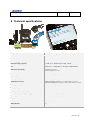
8 Technical specifications
Product
MiniCom® Guardian [Complete Kit CMC-1010-00-004]
External Communication standard
GSM /SMS
Power supply (standard)
DC input voltage (optional)
AC Adapter 230VAC -4,5VDC. / 2W
4,5 <VDC<7,5 V. Maximum input voltage 7,5V DC
CE
EN 61000-6-1 / 3 EN301489-1/7 EN 55022. LVD2006/95/EC
Dimensions (W x H x D)
Housing: 9 x 16 x 3 cm
Sensor housing: 4 x 4 x 2 cm
Environment
Indoor, or inside approved outdoor cabinet. DIN rail mount.
System setup
SMS
Sensor (Included)
External sensor, temperature and humidity
Temperature Accuracy
Overall Temperature accuracy +/- 1,0 °C from -20 °C to +70 °C
Guaranteed Temperature accuracy +/- 0,5 °C from +10 °C to + 40 °C
Humidity Accuracy
20 -80 % rel humidity +/- 3 pp
Factory Settings
MINTEMP=18 MAXTEMP=26 MINHUM=10 MAXHUM=60
Temperature Operating Range (Sensor)
-30 °C - + 80 °C
Humidity Operating Range (Sensor)
0 -100 % rel humidity (n.c .) +/- 7 pp
Operating Environment (MiniCom® Guardian)
0 - 40 °C Indoor. Outdoor in approved cabinet with heating
Display
3 x status LED
Keyboard
Single button operation
Battery Backup
Yes
Connection
RJ45 digital I/O
Page 16 of 16