1
INTERNET OPERATED
PROGRAMMABLE
RELAY
WITH ENCRYPTION
AND
AN ASTRONOMICAL TIMER
Table of contents
1.INTRODUCTION......................................................................................................................................4
1.1. About the software..............................................................................................................................4
1.2. A few words about safety....................................................................................................................4
2.BUILD.........................................................................................................................................................6
3.TECHNICAL SPECIFICATION.............................................................................................................8
4.ADDITIONALLY....................................................................................................................................10
4.1. Firmware...........................................................................................................................................10
4.2. Interfaces...........................................................................................................................................10
4.3. Safety code........................................................................................................................................11
4.4. Programming and operation..............................................................................................................12
4.5. A few words about the device's configuration...................................................................................13
4.6.The software’s main window.............................................................................................................14
5.CONTENTS OF THE PACKAGE..........................................................................................................15
6.SAFETY MEASURES YOU SHOULD COMPLY WITH AT ALL TIMES........................................15
7.FIRST RUN..............................................................................................................................................17
7.1.Password and SALT...........................................................................................................................18
7.2.Computer Network.............................................................................................................................25
7.3.Entering the device into the configuration and password saving mode..............................................26
8.TIME SYNCHRONIZATION................................................................................................................29
8.1. When do you need to synchronize the time using the USB cable?....................................................29
8.2. Battery..............................................................................................................................................29
8.3. Updating time in the computer..........................................................................................................29
8.4.What to remember about when making time related settings.............................................................31
8.5. How to synchronize time?.................................................................................................................36
9.MAIN CONFIGURATION.....................................................................................................................38
9.1. Network configuration......................................................................................................................40
9.2. What is an NTP server?.....................................................................................................................43
9.3. Geographic location of the device.....................................................................................................45
9.4. 12V battery charging parameters.......................................................................................................47
10.INPUTS & OUTPUTS...........................................................................................................................48
10.1. INPUTS..........................................................................................................................................49
10.1.1.First tab – INP...VIR – settings for physical and virtual inputs....................................50
10.1.2.Second and third tab.....................................................................................................55
10.1.3.The fourth tab – X variables and output relays............................................................59
10.1.4.The fifth tab – input operation using the astronomical clock and timers.....................61
10.1.5.The sixth tab – input and relay behavior after reset.....................................................64
10.1.6.The seventh tab – counters...........................................................................................65
10.1.7.The eighth tab – cooperation with other PLC2011 devices..........................................66
10.2.OUTPUTS.......................................................................................................................................74
11.MODBUS................................................................................................................................................75
12.ASTRO TIMER.....................................................................................................................................81
12.1. What is the Astro timer for..............................................................................................................82
12.2. How does the Astro timer work.......................................................................................................82
12.3. Where do you use the Astro timer...................................................................................................84
12.4. TIMER function – Night Breaks ( Night Intervals )........................................................................86
13.WWW SERVER.....................................................................................................................................94
14.HOW TO USE THE DEVICE – IN SHORT........................................................................................99
14.1.Starting the software........................................................................................................................99
14.2.Main window.................................................................................................................................100
14.3.Main window description...............................................................................................................102
14.4.USB CONSOLE tab.......................................................................................................................110
14.5.SETTINGS tab...............................................................................................................................111
14.5.1.Cryptographic salt for secret passwords.....................................................................111
14.5.2.Encryption tools..........................................................................................................112
14.5.3.SAVE/RESTORE configuration.................................................................................117
14.5.4.LANGUAGE selection...............................................................................................117
14.5.5.NTP settings................................................................................................................118
14.6.DEVICE A1 tab.............................................................................................................................119
14.6.1.Display ( radio buttons 1 to 5 )...................................................................................120
14.7.Adding a new device......................................................................................................................123
14.8.Resetting the device using the software.........................................................................................125
14.9.Operation in tray............................................................................................................................126
15.FIRMWARE UPDATE........................................................................................................................127
15.1.How to turn on the firmware update mode.....................................................................................127
15.2.Firmware update............................................................................................................................128
15.3.Errors during firmware update.......................................................................................................132
16.ADDITIONAL INFORMATION........................................................................................................133
1. INTRODUCTION
The device is more than just a programmable relay.
It's main tasks are:
•
•
1.1.
remote control of electrical circuits and devices through the Internet in a manner ensuring
absolute safety
automatic operation, without the user's constant supervision
About the software
The software for Windows does not have any functions that would spy on the user. It does
not steal data, connect to unknown internet addresses or to the manufacturer or the software's
author. No data are saved to the Windows registry system and all settings and configuration files
are created only in the folder containing the *.exe executable file. The software does not
automatically check for updates so the user's ip address and location are not logged. There are no
functions of this type.
Using this software is extremely safe, especially when you want to control a device placed in a
building far away. You can expose the relay's IP address to the public address pool or do a port
redirection at the router without any concern that the device will be broken into.
The relay cannot be broken into because it has no operating system able to execute a code received
from the outside. This problem does not exist at all due to how the device is built.
When running the software on Windows 7 you should be logged in as the administrator when you
want to edit the time server or firewall settings.
1.2.
A few words about safety
The device was designed with a lot of attention put on safety. An advanced, military
strength cryptographic system protects data from being intercepted during transmission and used
again, prevents unauthorized access to the device by people trying to impersonate the rightful user.
From now on you can safely open gates or roller shutters even on the other side of the planet
without fear that an intruder will intercept the Internet transmission and use it to break into your
house, open your gate or roller shutters or disarm the alarm.
The safety system is based on many factors
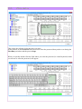
For the communication with the device to start you need to enter a long password. You do
this either using your keyboard or using your mouse and a virtual keyboard on your screen. This is
a means of defense against spy-software, especially programs which register keystroke.
The entered password is not transmitted through the Internet. This password is only used to
mathematically generate a substitutionary password using the SHA256 hash function. This digest
is also not transmitted through the Internet. The digest is used to encrypt the data between the
user's computer and the device, and is automatically wiped from the computer's memory before the
software is shut down. The long password you entered is overwritten in the memory when
approved and a memory dump after the software is closed will not reveal our secrets.
The device has a digest of an identical password, entered to it's own memory while it was
being configured through USB but does not have a password per se. It also does not have a
function reading anything from the device's memory that could reveal the password or it's digest. It
is impossible to extract the password through USB, the Internet or from electronic elements of the
device. You can only change the password personally after connecting the device to your computer
by an USB cable and entering the 12 byte PIN code which prevents unauthorized password change
through USB.
During the first phase, the password goes through one way hashing function SHA256. This
is a cryptographic function which changes any character string to a so called digest that is 256 bits
long (32 bytes). This digest will be used as a password to the actual encryption algorithm AES256, which requires a 256 bit long password.
Before a packet of data is encrypted, a 128 bit random number is generated, precisely the
same length as the block of data that is being processed by the AES-256 algorithm. From this
moment, a packet of data with commands transmitted to the device is formed. Placed in this packet
is also our computer's current system time with no more than a 15 second difference between the
device and the computer. The packet is then put through the XOR function with the generated
random number. The random number is generated separately for every packet. Next, the random
number and the packet are encrypted with the 256 bit digest. You say that a packet like this is time
stamped and encrypted. Additionally, every packet looks different thanks to the random numbers
and is only valid for 15 seconds after being formed. As the device has it's own independent realtime clock, the communication will work if the time stamp entered in the transmitted data packet
before encryption is the same (the difference can be up to 15 seconds) in the computer and in the
device. The password or digest are not processed at all during the transmission. The device
receives the packet and tries to decrypt it using the digest in it's memory. If the decryption is
unsuccessful, the device will not reply to the packet at all. It will not find data identifying the
sender, the time stamp will be incorrect, the data will be encrypted using a different key etc.
The way the data is encrypted is transparent and it's safety is not based on secret
algorithms. It's based mainly on the length of the password and whether or not you keep the
password to ourself or lose it. If you have any doubts whether your password is still safe you can
always change it through USB and using the PIN code, and reinstall the infected operating system.
Used security technologies:
•
•
•
Hash function SHA-256 - http://en.wikipedia.org/wiki/Sha256
Symmetrical encryption with the AES-256 algorithm - http://en.wikipedia.org/wiki/Aes256
Time stamping
2. BUILD
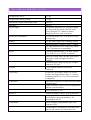
3. TECHNICAL SPECIFICATION
Weight of the device
0,35 kg
Weight of the whole package
0.70 kg
Dimensions length/width/height [mm]
144/90/57
Mounting
DIN rail
Power supply
An external, stabilized 15V 1A power-supply
unit. Plug with plus inside. The PSU must
always generate 15V. Otherwise battery
charging will be to weak or to heavy.
Electricity consumption
Ca. 1W with relays off + ca. 0.45W for every
working relay
Battery
12V gel battery input with a charging system
Maximum battery charging current – 100mA
Use VRLA batteries in the range from 2Ah to
17Ah. 7Ah batteries recommended.
Inputs
6 optically isolated binary ( two state ) inputs
( 110-230VAC or 12-24VDC if ordered)
Optically isolated inputs through optocouplers (
transoptors ) with a strength of at least
1500VAC
Maximum input voltage on any pair of input
connectors 250 VAC
Outputs
7 relay outputs with both NO and NC
connectors
Used relays
8A 250VAC for resistive loads. Use circuit
breakers not bigger than 6A type A – (fast) to
not damage the device. Use of circuit breakers
is obligatory.
Connectors
RJ45 Ethernet interface 10 Mbit used for remote
communication
USB 2.0 interface used for device configuration
and time synchronization
RS232 interface as TTL
Ethernet
10Mbit full duplex without polarity detection
A surge protector for the LAN and for the
power supply requires grounding!!! For
grounding use pin 22.
Additionally
Relay's complex programmable logic with
elements of PLC
A multichannel, astronomical clock that tracks
sunrises and sunsets, and which may also
cooperate with the built-in timer
Real-time clock synchronized with Internet time
via NTP
A web server for viewing on mobile phones,
tablets and computers
Data encryption system AES 256
Powerful yet easy to use software that allows
you to prepare the task and then verify its
correctness by simulation
4. ADDITIONALLY
4.1.
Firmware
This relay has an easy-to-use, user friendly firmware update function. Frequent firmware
updates will accommodate the device to the user's needs.
On request we can prepare additional functions for the device.
Firmware can be updated very conveniently through USB and any breaks in
communication will not result in damage to the device. Firmware update is secured by a long PIN
code so that no unauthorized persons can use this function. Every firmware is digitally signed
which ensures that only the manufacturer's firmware will work in the device.
4.2.
Interfaces
The device has all interfaces used for communication and no additional cords or adapters
are required. Standard computer network wiring is enough for the device to work properly. This
type of functionality is not found in any other device available on the market.
This type of functionality is not found in any other device available on
the market.
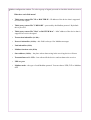
4.3.
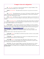
Safety code
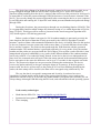
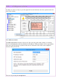
Code 147 – simply enter 147 into the field marked by the red arrow.
When you enter this code, the device will exit the 'safe mode'.
This mode protects you from accidentally clicking on an input, the RESET button or a relay.
It is a sort of a safety fuse.
After you enter the number 147, the screen will change color into light pink and all the options in
the program will be unlocked.
Pressing the small 'RESET' button, placed next to the field where you enter the code, will put the
device back into safe mode. In safe mode you can enter individual menus but you cannot click on
strategic places on the screen.
Another PIN code – 369 – also exists. It has a similar function as the one presented above
but it also makes the device send out packets 10 times per second. This mode is for testing the
bandwidth.
4.4.
Programming and operation
This is not a typical programmable relay. You do not program it in the STL language or
build a LAD ladder.
This is a relay programmable by building logic functions using available variables,
intended for people who do not have time to learn how to program relays but who need to carry out
a quick modernization of their electrical installation, who want to equip it with additional logical
functions, temporal dependencies between circuits but first and foremost who want to control the
installation using the Internet without having to worry whether the transmission is safe.
With this one device you can replace several different
types of timer relays.
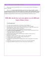
Possible applications
1. To control entry or garage gates at your house, shop, company etc.
2. To control how your boiler room works, turn on and off furnaces, pumps
3. Watering gardens, pitches, fields, all kinds of green terrain e.g. right after sunset or just
before sunrise (controlled with the Astro timer)
4. To control roller shutters, motors, lighting based on the Astro timer
5. To control by yourself through logical functions, the timer and the Astronomical Clock
6. Control over the relay via the Internet
7. Supervision and status check using a cell phone
8. Cooperation with access systems, alarms
9. Remote starting, shutting down, and restarting of computers, network devices
10. Starting power-generators
11. Multi-way ( staircase ) switches based on the time of day and night
12. Counting people, employees, clients coming in and going out
13. Counting electric energy consumption
14. Economically efficient control over lighting and heating, keeping them on only when
necessary
15. Various other applications that depend on user's needs, ideas and imagination
16. Equipping installations and devices with a safe, Internet control system
4.5.
A few words about the device's configuration
In this manual we will describe individual block components but we will not be teaching
programming.
Programming lessons will be available as video tutorials/instructions and will be based on
simple examples.
The relay is not programmed literally. It is configured using a simple menu.
Relay is configured using the included software.
Configuration looks like this:
1. Pick the type and mode of operation of individual inputs
2. Set the relations between input operation and Astro Timer events
3. Build equations which include the full set of relations and events which you want to occur
to trigger the activation of subsequent functions or variables
4. Direct the equation result to the chosen inputs
To sum up, it works this way:
•
From the input configuration tab you receive the INP or I signal
•
The INP or I signal is directed to the T timers or X variables and processed before being
directed to the RELAY or it can be directed straight to the RELAY
•
Any INP or I can be directed to any T or X variable.
•
You can also set the feedback from the relays or X variables.
•
Additionally you now have 3 virtual inputs V1, V2 and V3.
You can click them using the PC or the Android software, however they do not have any
corresponding electrical inputs.
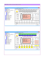
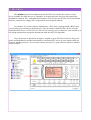
4.6. The software’s main window
5. CONTENTS OF THE PACKAGE
1.
2.
3.
4.
The device
USB cable for connecting the device to a computer ( 1,8 m )
Stabilized, impulse15VDC Power Supply Unit
CD with drivers, the user's manual and basic version of the software
6. SAFETY MEASURES YOU SHOULD COMPLY WITH AT ALL
TIMES
•
•
•
Before unpacking you should check whether or not the package has been damaged during
transport
After unpacking you should check whether or not the device is mechanically damaged in a
visible way. Do not start the device if you have any doubts. In this case contact the seller.
Before starting the device you should read the manual, especially the part regarding
safety.
ATTENTION!!!
The device should be installed and wired up only by a qualified electrician.
Working with high voltages over 28V AC or DC can result in serious injury or death.
ATTENTION!!!
The device can only be used with triple-wire electrical installations with a separate PE ground
wire. Connector #22 (the first one from the top, on the left side of the device) must be connected to
a working Protective Earth/Ground wire. You cannot connect the neutral N wire or leave the
connector unused.
ATTENTION!!!
Large, induction loads (over 1A) must not be connected directly to the relays as it may cause
damage to their connectors. You must also not connect large amounts of fluorescent lamps with
induction electrical ballast. Such installations should be made using an external contactor.
ATTENTION!!!
Every relay output should be secured with a circuit breaker not bigger than 6A type A – a so called
fast circuit breaker. Exceeding that value may lead to relay output damage.
ATTENTION!!!
Connection to mains electricity must be done accordingly to the manufacturer's instructions and
applying safety measures.
Use only the power supply unit provided by the manufacturer together with the device. The
electrical outlet to which you plan on connecting the device, should itself be connected to a
switchgear equipped with appropriate fuses and circuit-breakers (RCDs) to ensure that the user is
safe from being electrocuted.
All voltages going through the device's relays' connectors should also come from circuits equipped
with circuit-breakers and fuses. Appropriate fuses should be chosen by a qualified installer.
The electrical installation should be done by licensed personnel and in accordance with safety
standards and applying norms.
The manufacturer and distributor are not responsible for any injuries to a third-party or damage
done to objects as a result of not following the instructions above.
7. FIRST RUN
In short:
1. You configure the network addresses and set up the password through an USB cable
2. You synchronize time through an USB cable
The first run can only be carried out using an USB cable. You cannot do it
through the local computer network. It is a safety measure so that the password
cannot be changed remotely. You can only change the password if you connect
with the device directly using an USB cable.
To run the device for the first time you also need the PIN code.
This code is placed on the cover of the CD containing drivers.
This code must not be lost! Without it you will not be able to re-acquire control
over the relay if you lose or forget your password.
The purpose of the first run is to set the device's:
1.
2.
3.
4.
Network addresses
TCP/IP protocol port numbers
Time zone
Password
7.1. Password and SALT
The password should have at least 15 characters to be sure that device is immune to
hacker attempts at guessing or breaking the password. In buildings of heavy importance the
recommended password length is over 24 characters.
In the older software versions the password had to be at least 15 characters long and you could not
save the configuration if the password was too short. There was no way of surpassing this
requirement due to user safety.
In the newer versions of the software you can now create a shorter password or an empty
password (the password field is left empty). This is due to frequent user requests motivated by
operation convenience.
However, we advise you to use a password of at least 15 characters.
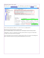
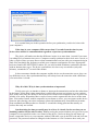
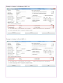
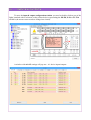
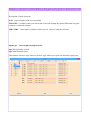
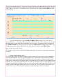
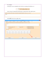
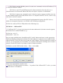
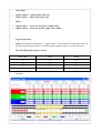
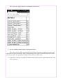
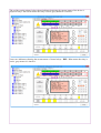
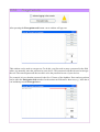
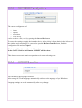
If the password is too short then the following message will display in the console.
The configuration will be saved but the following message will be displayed:
Password is too short.
The field where the password is entered will be in red. This is to show that the password is shorter
than 15 characters.
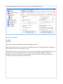
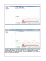
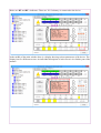
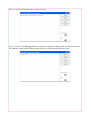
If the password is 15 characters or longer the message in the console will look like this:
Configuration was saved.
The field where you enter the password has changed to green which means the password is 15
characters or longer.
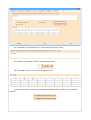
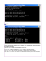
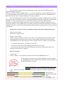
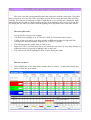
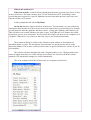
Information shown in the console
The first part is a cryptographic hash ( also called digest ) generated using SHA-256 function.
In our case the password is fifteen "1" ( 111111111111111 ) without SALT.
Hash for this password will always look the same:
D3447652BB8A5FBB29C85423666D645A50C12D47B9B037D2E0E326EF0922ABEA
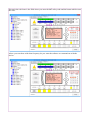
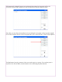
Additionally, to make it even harder to break the password, that it is to guess it if the hash is
revealed, you can turn on the SALT function.
Salt is data added to the password before hashing with the SHA-256 function. It's nothing more
than a connection of the text of your password and another, non secret text.
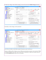
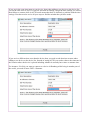
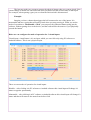
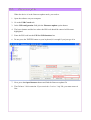
To activate the SALT function we have to go to the SETTINGS tab first.
You have two options
Salt PLC
Salt TXT
Only the first function is important when assigning a password.
Both of the Salt functions are switched on by default and consist of a random string of characters.
In the fields you can enter any Salt you want.
The Salt can consist of up to 64 characters. The characters should be entered randomly. It is also a
good idea to use special characters such as letters written in different alphabets. The more
complicated, the better. Both Salts must be different from each other. More about Salt for text
messages is written in a latter part of the manual.
To make any changes to the default settings you must first check the Enable changes checkbox.
The ability to make changes will be unlocked.
You will now be able to switch Salt on and off and enter your own Salt text.
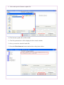
Using two different Salts will give you two different encryption keys for the same password. When
you send commands to your PLC device they will be encrypted in a different way than when you
use the Encryption tools window for text messages.
After you save the changes with the SAVE button the ability to modify the settings will be blocked
until you check the Enable changes checkbox again.
To return to default settings you need to press the Reset button while remembering to first check
the Enable changes checkbox.
The settings will be changed to the default settings and the ability to make changes will be blocked
until you check the Enable changes checkbox again.
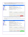
The values entered in these fields are kept in an XML file in the folder with the software to control
the PLC.
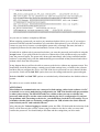
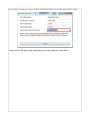
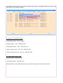
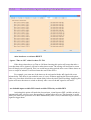
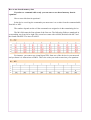
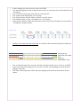
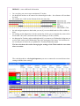
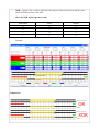
Below you have a comparison of a password hash for the same password (fifteen “ones”):
– without Salt
– with the default Salt
As you can see, both are completely different.
When assigning a password you need to pay attention whether Salt is on or not. If you assign a
password with Salt switched on and then you switch the Salt option off, you will not be able to
connect to your device because even though the password is seemingly the same, the hash is
completely different for the salted and unsalted versions of the password.
A hash with or without salt is generated each time you enter the password and confirm it using the
Accept button. If you pick from the list a device without salt or with a different salt, you need to
enter the password again. The password is destroyed immediately after being confirmed and the
software is operating solely with the mathematically processed hash of that password and with or
without values from the Salt options.
It may happen that you will not be able to connect to the device without any apparent reason. You
should then check the Salt settings, remind yourself what settings have you made in the software
and how did you configure the device via USB. If the device password was set without Salt then
you need to switch off the Salt PLC option, then save the settings and enter the password again.
Both the Salt PLC and Salt TXT options are switched on by default and use the default values to
operate.
We advise to use even the default values.
ATTENTION!
Most failures in communication are connected to Salt settings, either in the software for PC
or Android, or to errors made during configuration via USB. You should really pay attention
to what you are doing. The SHA-256 hashes are visible so that you can see whether the
password with salt gives out the same result as during the device configuration. If you have
any problems with connecting to the device, you should first check the SALT settings. Try to
remember whether Salt was on during configuration via USB, whether the Salt is now the
same in both your PC and Android software.
After choosing the Verbose logging to console option, the SHA-256 hash with the inclusion of the
SALT will be shown in the console, when trying to connect to the device after you enter and
confirm the password. You should analyze this data and the settings that you have made.
7.2. Computer Network
The computer network parameters must be set accurately as otherwise there is no chance of
connecting with the device. Remember to enter the IP address with the dots, do not enter other
characters. You configure the device, entering network addresses and the password, 'blindly'. There
is no possibility or any function of the device or software that will enable you to retrieve the
password or set parameters if communication through the computer network is lost or you forget
your passwords. In this case you need to use the PIN code and then reenter all the parameters. The
values seen in the configuration window at the moment are only default values, an example of how
the values should be entered, and you need to change them to your own values. Those values are
not read from the device, they are entered by the software itself only as an example.
Every device should have a unique IP address and network interface MAC address, these
two parameters are the minimum that should differ the devices from each other. Otherwise there
will be conflicts in the local network. The computer you are planning to use for testing should
belong to the same subnetwork as the device whose IP address you have entered ( Relay ).
First, we must set up our computer, at least for a while, to be sure that a connection is possible.
Network addresses in our computer should be set statically.
Our computer's IP address should be set to 10.0.5.2
Our subnet mask should be set to 255.255.255.0
Our gateway should be set to that of the router's – usually ends with '1' – 10.0.5.1
Save the network settings.
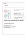
7.3. Entering the device into the configuration and password saving
mode
1. Connect the power supply unit to the device.
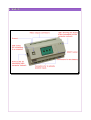
2. Connect the device with your computer using an USB cable – the USB socket is on the left
side of the front panel
3. Wait ca. 10 seconds
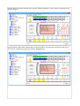
4. Press the round RESET button on the device's casing
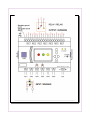
5. Keep the RESET button pressed until all 3 LEDs turn on, then only the red will stay on,
next the red LED will turn off and the yellow will turn on again. When the yellow LED
turns on you need to release the RESET button. The green LED will turn and stay on.
All LEDs simultaneously
red LED
yellow LED (release RESET)
green LED stays on
The device entered the new configuration and
password saving mode or the firmware update
mode. It is the same mode.
6.
7.
8.
9.
Keep the device in this mode with the green LED staying on
Run the software ( on the CD in the package ) on the computer
Enter the first tab ('USB CONSOLE') in the main window
In the 'USB configuration' field click the 'Save configuration' option button. Appropriate
boxes will become highlighted.
10. Assuming the default values stay unaltered, you only need to enter the PIN code from the
sticker on your CD cover, enter an at least 15 character password in the password text box,
set the time zone and mark whether or not the device is placed in a location in which
summer is during winter in Europe (southern hemisphere) e.g in Australia. The time zone is
very important as you need the correct time to be able to connect to the device through the
LAN. The PIN code text box is in the lower right corner. We remind you once more that a
password shorter than 15 characters will not be accepted and configuration parameters will
not be saved to the device.
11. The failure of this operation is usually caused by entering a wrong PIN. For example,
make sure that you have distinguished the number '1' from the letter 'l' or the number
'0' from letter 'O'
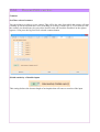
12. Press the configuration saving button – Save configuration
13. If the actions presented above are executed properly then in the text window you will see a
message with the digest of your password. It is the proper password which will be used to
encrypt the transmission. Do not save the digest. It is of no use to us and can help hackers.
The digest is presented only to slake the user's curiosity during the first configuration and
should not be saved anywhere.
14. After this action, communication will not yet be possible. On the left side of the program
window you will see that your device has been added but you must synchronize time before
communication between the device and the computer network is possible. If you enter
different IP addresses you must also change the device's description in the device list on the
left. Without a proper entry on the device list, you will not be able to connect with the
device by LAN or the Internet.
15. After completing these actions press the RESET button and wait until the device reboots
itself an enters it's normal work mode. From this moment the device's WWW website will
be working and you can ping the device's IP address.
16. To see if this is true open your web browser and type in “http://10.0.5.100” or whatever
other IP address you have given the device. Our devices web server response should show
up.
17. You can also open menu START->Run and type in the command “ping -t 10.0.5.100” or
other given IP address. Remember to type without the quotation marks.
18. Communication using software will not yet be possible due to safety concerns as the
software allows you to deeply interfere with the device and switch the relays. You still
need to do a one-time time synchronization.
19. Please watch the video manual and read the chapter about time synchronization.
8. TIME SYNCHRONIZATION
8.1.
When do you need to synchronize the time using the USB
cable?
1. After you run the device for the first time and save the password and network settings
2. Every time you unplug the main power supply and the battery, meaning after a total loss of
power supply
8.2.
Battery
A battery must be connected to the device at all times.
Without a battery you will need to connect the device with a computer using an USB cable and
synchronize time every time there is a loss of power supply.
During a period of power outage, the device should work on a battery so that you can
connect to the device via the computer network and remotely check the cause of the power
loss. Therefor a battery should always be used. This allows us not to worry about connecting the
device to a computer and synchronizing time every time there is a power outage. We recommend
that you use a 7Ah gel battery.
Without the time set correctly the features related to the Astronomical clock will
malfunction or not function at all.
Admittedly, the device does have automatic synchronization and downloads the correct
time from NTP server set by us but only within the range of the same minute. The year, month,
day, hour, minute and day of the week must all match. After a loss of power the time and date will
be calculated from zero so communication will be impossible.
8.3.
Updating time in the computer
Before you update the time in your device, you first need to update the time in your
computer. Some clocks in computer can be ahead or behind the actual time even ten-odd seconds.
This is not a good occurrence. Synchronization of time in the device means you download the time
from your computer to the device via an USB cable. This means you need to have the correct time
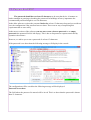
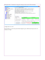
set in your computer. In any Windows operation system updating time is easy. Just double-click on
the clock in the lower right corner of your screen, at the end of the task bar. The 'Date and time
properties' window will pop-out. In this window in the 'Internet time' tab you will find a button
used to update the time.
It is essential that you do this operation before you synchronize your device's time with
your computer's.
If the time in your computer differs more than 15 seconds from the time in your
device, there will be no communication regardless of previous synchronization.
The device will make sure that the difference in time is no more than 1 second if you enter
a working IP for a Internet time server. Computers usually synchronize their clock once a week, so
after a couple of days you may discover that communication was lost with your computer being at
fault. You can change the frequency at which your computer synchronizes it's time. Appropriate
tools are found in the 'SETTINGS' window. So, you need to make Windows synchronize the time
with an Internet time server. The device synchronizes it's time every two minutes (only odd
minutes), around the 30th second of the minute.
It does not matter whether the computer and the device use the same time server, they can
use different servers, after synchronization they will always have the same time with a difference
of no more than 1 second.
Why all of this? Why is time synchronization so important?
If only not to give an intruder a chance to intercept the transmission and use the stolen data
in the future. All the data is time stamped an is valid in the present, not an hour or even a minute
later. In the same time, the ability to access the device from several computer at once is preserved.
All this is for safety. Remember that a couple of users can be connected to the device at the same
time. You can have small, mobile computers in your home or office, you can connect to the device
from one place having your other computers connected simultaneously from different locations.
Sent commands and data packets are invalid 15 second after being generated but usually are
useless after only one second.
Synchronizing the time personally may be a bit a of a hassle for the user but you are
shedding comfort for the sake of safety. Without seeing the password when you type it in to your
computer it is not possible to take over control of the device. And even then you can always go
home, connect the device to your computer with an USB cable, type in the PIN code and set a new
password. The password cannot be changed via the Internet so even if someone does steal your
password, he will not be able to change it afterwards. You always have the possibility to take away
access to the device by changing the password.
Remember that if you lose the PIN code you received with the device, you will not be
able to change the password ever again. Therefor this code should be kept safe. It has been
generated automatically and the manufacturer does not posses a copy. The PIN code is written into
the device permanently and cannot be changed. When entering the password, remember different
letter sizes are recognized.
The PIN code is not needed for time synchronization.
The only thing you need is the password you have entered when you started the device for the first
time. The PIN code is used for the first and any other configuration and firmware update.
8.4. What to remember about when making time related settings
You need to ensure that the device always has the most up-to-date time as possible. Before
synchronizing the time in the device with the time in your computer you must download the
current time from an internet time server. You should not synchronize time if you entered the time
in your computer manually. It is highly probable that when the computer finally downloads the
time from a time server, the difference between the accurate time and what you entered manually
and wrote into your device is so big that you will lose the ability to connect to the device. In this
case you would need to synchronize the time again. However, if you download the accurate time
from the internet from the beginning then you will avoid such problems.
Remember to properly set the time zone where the device is mounted. For example, if the
device is in a place where the time zone is GMT+10 but during synchronization you set the time
zone to GMT+1 then the device will have problem with communication with the time server and
will not update it's time. You do not change time zones when switching from winter to summer
time or back. A properly configured device will take care of it itself. For example, if you place the
device in Melbourne or Sydney then during the summer you should not change the time zone from
GMT+10 to GMT+11, the software will do it for you automatically. Analogically, if you place it in
Paris, Berlin or Rome then during the summer the time zone stays GMT+1, you do not change it to
GMT+2. If the device is placed in the southern hemisphere then remember to check the check
box for the option that makes the device recognize this. Otherwise the device will not properly
recognize it's time zone and time changes will be executed in an improper manner.
Example of settings for a device located in Paris:
Example of settings for a device located in Melbourne:
Remember to enter the rules concerning time changes in the location of the device. If you choose
wrong months, days or hours of the time changes then in the moment when the time actually
changes, either in the device or in your computer, connection with the device will be lost because
the time will suddenly become incorrect.
Example of settings for Melbourne (GMT+10)
Example of settings for Paris (GMT+1)
If you are in the same time zone as your device, then when adding a new device to the device list
you set the time zone to AUTO. If you are sure that all settings, except the time settings, are correct
then failure to connect while in AUTO mode means that there is definitely a problem with the time
settings. You then need to revise all your steps to find the mistake that you have made.
If you are in a different time zone than the device then you need to take that into account when
adding a new device to the device list. Instead of setting AUTO you need to choose the timezone in
the location where the device is placed including whether it currently has winter or summer time.
For instance, if in July you want to connect to a device in Hamburg while being in another part of
the world, you need to enter GMT+1 Summer.
If you want to connect to a device in New York in December, you need to enter GMT-5 Winter.
You use the AUTO option only when being in the same timezone as the device.
8.5.
How to synchronize time?
To synchronize time you need to enter the device into the time synchronization mode.
1. Press and hold the arrow button on the front panel ( left “<-” or right “->” ).
2. Holding the arrow button, press shortly the round RESET button (do not hold!) .
3. At first, all 3 LEDs will turn on and then off. Next the red LED will blink and then the
yellow LED will turn and stay on.
4. Keep holding the arrow button until the yellow LED goes on.
5. Release the arrow button.
6. The device is now in time synchronization mode.
7. In the 'USB console' tab click the Synchronize time round option button.
8. Boxes needed for this operation will become highlighted.
9. You need to set the timezone, enter your password and press the 'Time synchronization'
button. After a second you should get the message shown below and the device will reboot
itself. If thb43e password entered is incorrect, the device will not reset and the red LED on
the left will switch on. In this case you need to reenter the password correctly.
10. From this moment communication between the device and the computer should be
working.
11. After synchronization you do not need to reenter the password when switching to the
'Device' tab.
12. Sometimes you need to close and reopen the added device on the device list on the left.
Double-click to collapse and the double-click again to expand. This should initiate the IP
addresses again.
ATTENTION!!!
The main causes of failure in achieving connection between the device and a computer are
wrong time, wrong timezone or inaccurate network parameters. As the timezone you should enter
it's name e.g. Europe/Berlin, set AUTO for local time or enter as GMT+2, GMT+1, GMT etc.
Entering the precise name of the timezone in which the relay is located (Europe/Berlin) gives you
certainty that summer and winter time will be included automatically.
Your computer's local time and timezone are not important. You can be in any timezone
you wish. The relay however is mounted in a certain timezone with certain rules regarding
switching from summer to winter time and back. For instance, if you mount the relay in Moscow,
the timezone should be 'Europe/Moscow'.
9. MAIN CONFIGURATION
The main configuration panel is designed to change the devices settings using the Internet,
after you have successfully executed the 'First Run' procedure and synchronized time, meaning you
should now be able to communicate with the device via the Internet. You will not be able to use
this option without proper communication with the device.
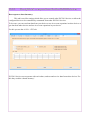
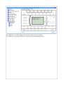
To enter the main configuration panel press the Main configuration button in the
program's main screen. On the picture below this button is marked with a red arrow.
A window with the main configuration panel will pop out
The following settings can be changed in this window:
1. All parameters of the computer network
2. The geographical coordinates of the device's localization
3. Set the time zone, the way of calculating the day of the switch from standard to summer
time (DST) and back, and mark whether or not the device is placed in a location in which
summer is during winter in Europe (southern hemisphere) e.g in Australia
4. Battery loading parameters
5. Switch RS232 on or off
6. Switch ethernet full duplex on or off. We recommend to switch off full duplex to reduce
interference between the signals in the computer network cable.
7. You cannot change the password. The password can only be changed when the device is
connected to your computer via an USB cable and you enter the PIN code.
Be careful and know what you are doing when configuring the
computer network. If you enter a wrong parameter you will not be
able to communicate with the device. You will then have to connect
the device to a computer with an USB cable and use the PIN code to
execute the First Run procedure again.
You will not need to synchronize time again if the only thing wrong is the IP address.
If you keep the device at your house then configuring again using an USB cable will not be
a big hassle, but if it's at your company or shop then you will lose precious time to get there and
reconfigure the device. The transmission is secured using a couple of methods, including
cryptographically, and there is no chance that the lack of communication is caused by the device. If
a packet has even 1 bit corrupted is not possible to decrypt the packet, the whole packet will be
recognized as invalid and rejected by the device.
9.1.
Network configuration
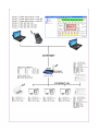
An example of how the network can be configured is shown on the next diagram.
Presented network addresses are just the exemplary settings. Your
real addresses and router configuration should be provided to you by
your network administrator.
The relay must have an invariable static IP address or otherwise you will not be able to
connect to the device from outside the local network or even in the local network. Your every
device must have a static IP known to you if you want to communicate with it.
It is also good to have a public, static IP address visible from the Internet. If that is a
problem, you can also use DDNS services (dynamic domain name system). Router configuration is
up to the network administrator. Every router is different and therefor you should read it's manual
or ask the administrator.
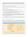
Example of network configuration
IP: 10.0.5.100 – every device in a local network must have a unique IP address. There
cannot be two identical IP addresses in a LAN segment.
MASK: 255.255.255.0 – The subnet mask is the same for every device in a Local Area
Network.
GW: 10.0.5.1 – The default gateway is the router's LAN interface IP address. The router's
address depends on the settings done by the network administrator. A router can be a dedicated
device or one of the computer in the network.
NTP: 10.0.5.1 – An NTP server (time server) can be any computer, or even the router, if it
has a time server function. It can be any computer on the Internet, your network or even your own
computer.
MAC: 00:11:12:13:14:15 – The MAC address must be unique in the whole Local Network
Area. It's the physical address of the Network Interface Controller in the device. There cannot be
two identical MAC addresses in one LAN segment.
WWW PORT: 80 - The TCP port at which the device's WWW server listens. Normally
this port is set to 80. If you change this value then after entering the address in a web browser you
need to add ' :port_number '. For example, if you change the port to 81 then you need to type in '
http://10.0.5.101:81 ' or ' http://www.myrouter.com:81 '.
If you enter 0 as the port number, the WWW server in the device will be switched off.
If you enter 80 as the port number, you will not have to add the colon and port number to the
address.
The port number can be a value in the range from 1 to 65535.
UDP PORT: 27136 - The UDP port at which the relay listens. It can be set to any number
in the range from 1 to 65535.
NTP PORT: 123 – UDP port that the relay connects to. It is usually the time server port
and you should expect the time server will use this port.
OUT PORT: 27015 - Local exit port for the UDP packets. When the device sends a
message to the NTP server, it sets this number as the source's port and awaits a response at this
port. It can be set to any number in the range from 1 to 65535.
STATIC IP – The router assigns IP addresses statically. This means the device will not
acquire a new network address each time it is connecting to the network but you must set a
permanent IP address. An example of how to set addresses of devices inside a network is shown on
the picture below.
9.2.
What is an NTP server?
An NTP server is also called a time server. It is used to give us the current time. It
synchronizes itself to another computer in the Internet or an atomic time standard.
It's very important for communication with the relays that you
have the actual current time. Computers used to control the device
should have their times synchronized with an Internet time standard.
If the time in your computer and the time in your device differ by
more than 15 seconds, the communication between them will be lost.
This does not mean however that the communication has been lost for good.
Communication will be regained if you synchronize your computer's time to an Internet or your
own time server.
If you use several relays, you should not set the same time server for every one of them.
This time server will be flooded by packets coming from several devices, looking as if they all
came from one source. This may cause the NTP server administrator to refuse you access to his
server. This regards public NTP servers available on the internet.
In this case you can use a local device, like your router, to be the NTP server for your
devices. The router would then synchronize it's time with an external NTP server and your relays
would synchronize their time to the router without flooding an external NTP server. Your own time
server would be able to handle a lot of your devices without creating too much traffic on an
external server that does not belong to you but allows you access. You can also use a different NTP
server for each of your devices.
NTP server addresses can be found using Internet search engines. There are lots of these
servers and you should pick the ones close to your location.
The safest method is to set one of the computers in your local network or your router as the
NTP server. The computer will not have to work all the time. It should be on every 2-3 days so that
the relays can download the current time.
If the NTP server is not switched on continuously then it may happen sporadically that a
command sent to the relay will not be executed. This occurs because when checking the
communication with the NTP server, the device also checks communication with the local
network. The relay the executes a short network settings initiation procedure which may cause loss
of a command that was supposed to get to the relay at that moment. This is a way of protection
against freezing. The relay must send out a question and receive an answer from the NTP server. If
there is no response, data packets will be removed and network settings will be initiated again.
The relay logic processes are not disrupted.
You need to make sure the computer frequently synchronizes time with the Internet. This is
the safest method as it eliminates the risk of using a fake time server or someone manipulating
with the time server. Any computer with any Windows system can be a time server. In some
systems the time server option is turned off by default. You can switch it on using the tools in the
'SETTINGS' tab. Also, unblock port 123 in the Windows Firewall. For your laptop to become your
time server you need to start the server service, set your laptop's update time to 3600s and unblock
a port in the firewall. If you are using your laptop in your office even for only five minutes it will
be enough for the relays to update the time.
It is good to have a continuously working router with a time server.
9.3.
Geographic location of the device
In the devices location fields enter the geographical coordinates of the place where the
device is mounted. They are required for the Astro timer to work correctly. The Astro timer uses
this data to calculate the sun's position based on the location on Earth. You must also set your time
zone in relation to the universal time (UT, UTC, GMT).
The next field contains options regarding automatic changes from standard time to summer
time and back. For example, summer time starts on the last Sunday of March at 2:00 (A.M.) and
ends on the last Sunday of October at 3:00 (A.M.). You can set this settings adequately for your
region and in following years the time changes will be made automatically.
In this field there is one more important box. The options here are:
1.
2.
3.
4.
5.
6.
Winter time (+0h), (-0.833°), astronomic twilight
Summer time (+1h), (-0.833°), astronomic twilight
Winter time (+0h), (-6.000°), civil twilight
Summer time (+1h), (-6.000°), civil twilight
Auto Summer time, (-0.833°), Summer time honored for Sun calculations
Auto Summer time, (-6.000°), Summer time honored for Sun calculations
[RECOMMENDED]
7. Auto Summer time, (-0.833°), Summer time disabled for Sun calculations
8. Auto Summer time, (-6.000°), Summer time disabled for Sun calculations
•
Picking fields 1 to 4 will mean that you have to set winter and summer time manually. On
the day that the time is changed you need to connect to the device and change it's time
accordingly. After changing the time, the connection between the computer and the
device will be lost as there will now be an hour of time difference. After you change
your computer's time, the connection should be restored.
•
Picking fields 5 to 8 will mean that the time change will be done automatically on the dates
set above.
Astronomic twilight – the center of the Sun is -0.833° below the horizon. The Sun is not
visible however the sky is still pretty bright. This is the time between sunset and dusk and between
dawn and sunrise.
Civil twilight – the center of the Sun is -6° below the horizon. The Sun has not been visible
for a long time now. At dusk it is almost completely dark. At dawn it is starting to get bright.
“Summer time honored” – an hour will be added to the astronomical time during summer.
The Astro timer is also corrected by an hour during summer.
“ Summer time disabled” – during summer the astronomical time will not be changed and
an hour will not be added to sunset/sunrise calculations
This does not influence the three additional 'break' time periods that you can set
individually for every day of the week ( timer ). These periods of time are always based on the
current local time that changes from winter time to summer time and back. An hour will not be
added to sunrise and sunset times, they will always stay in winter time – in relation to bars 1 and 2
in the Astro timer.
The default setting, appropriate for most users, is setting 6. In this
setting everything is automatic. Twilight is set to civil, during summer
an hour is added to the astronomical time.
At the bottom there is the Summer is during European Winter check-box. Tick it only if
your device is actually in a place where summer is during European winter (southern hemisphere)
such as Australia.
9.4.
12V battery charging parameters
In the upper right corner there are two parameters – ADC voltage correction for proper
measurement and ADC value when we treat battery as connected.
Remember that what type of battery (what capacity or if it is used or brand new) you use is
only your decision. Therefore you have the ability to calibrate the parameters.
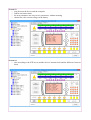
The current voltage on the battery clamps can be seen on the screen on the main window
after you click the '3' option button. Other useful and interesting data will also be shown. If the
voltage value is not equal to the value measured using a universal meter then you can make
calibrations by adding or subtracting the value you feel is appropriate in the ADC voltage
correction for proper measurement box. You need to save the settings for them to take effect and
results to be visible. If the results are not satisfactory, correct the settings until they are.
The second parameter is the moment when the battery is treated as connected. A brand new,
properly functioning battery does not consume power when it is fully charged. The battery is
charged to a voltage of about 13.5V and then flow of electricity stops almost completely.
The ADC value when we treat battery as connected parameter gives you the ability to
correct the detection voltage drop of the connected battery. If the battery is detected, two 'lamps' in
the software's main window will switch on. In the software, these 'lamps' are placed where the
battery connectors are in the actual device. If the set value of this parameter is too low, the 'lamps'
will switch off near the end of the charging period.
The following steps should be taken:
1. First, correct voltage readings with regard to the universal meter. 1 ADC unit corresponds
to around 0.01V.
2. Next, read the ADC value from the software with the battery disconnected.
3. Enter this value into the ADC value when we treat battery as connected field and
subtract +/- 10 units by clicking the down arrow.
4. Save the parameters and check whether they are working correctly. Check whether the
'lamps' switch off when the battery is disconnected.
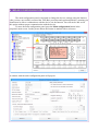
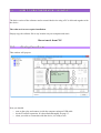
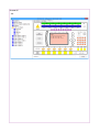
10.
INPUTS & OUTPUTS
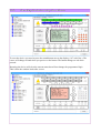
To enter the input & output configuration window you need to double-click on one of the
'lights' (marked with a red arrow on the picture below) representing the X0-X8, I1-I6 or T1-T16
variables (the mouse cursor needs to change into a hand).
A window with A1 O/I settings will pop out – A1 device inputs/outputs.
10.1.
INPUTS
The device has 6 physical and 3 virtual inputs.
Physical inputs.
Every input has a built-in optocoupler that separates the dangerous mains electricity voltage
from the device circuit.
The inputs are adapted to an 110 - 230 VAC ( alternative current ) but there is a possibility
to re-adapt them to a low voltage (12-24 V) direct current. Any input may be re-adapted
individually. If you are interested in re-adapting your inputs, please contact us.
You may also order a device with inputs already configured as
per your request.
The voltages on the input do not have to be equal in phase, they may be different from each
other. The device synchronizes itself to each input so that 50/60Hz voltage can be detected
doubtlessly. Each voltage can be powered by voltage of different amplitude, frequency and phase.
The inputs do not measure the voltage. They are Normally Open/Normally Closed inputs.
10.1.1.
First tab – INP...VIR – settings for physical and virtual inputs
Description of used acronyms:
I1-I6 – physical inputs with screw terminals
INP1-INP6 – variables which you can switch on and off clicking the inputs INP button using the
computer or Android software
VIR1-VIR3 – virtual inputs, variables which you can ‘click on’ using the software
Input type – concerns physical inputs I1-I6:
type NC (Normally closed)
type NO (Normally open)
This module converses logic states to positive logic where true equals one and false equals zero.
Mode of operation:
You pick how do you want the input to behave. Whether it should be monostable or bistable
(refers to physical inputs I1-I6, variables INP1-INP6)
“ + Click” gives us the ability to influence the physical, electric input by defining it's status using
the computer software.
In the current software version you can choose from five modes of operation.
Monostable – the physical input operates monostably, it's status cannot be changed using the PC
or Android software.
Bistable + click - the physical input operates bistably and you can additionally force a permanent
change in status using the PC or Android software.
Monostable + click – the physical input operates monostably and you can additionally force an
instantaneous change in it's status using the PC or Android software.
Likely bistable – the physical input is disconnected from the relay and works only as a voltage
detector in the PC or Android software. You can click the input using a command with the 'likely'
option in the Android software and the result will be a conditional switch to the opposite status.
Likely monostable – the physical input is disconnected from the relay and works only as a voltage
detector in the PC or Android software. You can click the input using a command with the 'likely'
option in the Android software and the result will be a conditional impulse.
The last two modes are present to protect the physical inputs when you want to check if the
remote change of status was successful but when you do not use the electric status of that input.
For example, when opening a gate you see when the limit switch is disconnected.
Example:
Imagine you have a button that triggers the bell connected to one of the inputs. It is
monostable and has a spring that will push it back when you stop pressing it. When you set the
mode of operation to “Monostable + click” you can press the connected button using just the
software, without getting close to the device, and the result will be the same as if you physically
pressed the button.
Below we can configure the mode of operation for 3 virtual inputs
Virtual input ( virtual button ) it is an input, which you can click only using PC software or
Android software. This is not a physical input.
There are two modes of operation for virtual inputs:
Bistable – after clicking it in PC software or Android software this virtual input will change it’s
status to opposite permanently.
Monostable – after clicking it in PC software or Android software this virtual input will change it’s
status and then will return to the status from before click.
In parenthesis in the mode of operation selection field you have commands which you can use with
each mode in the Android software.
For inputs I1-I6 and INP1-INP6:
- monostable mode – does not apply
- bistable mode + click - INP, INS, INC
- monostable mode + click – INP, INS, INC
- likely bistable mode – ISL, ICL, INP, INS, INC
- likely monostable mode - ISL, ICL, INP, INS, INC
For virtual inputs VIR1-VIR3:
- bistable mode – INP, INS, INC
- monostable mode – INP, INS, INC
Android software command descriptions are placed in the manual for Android software.
Feedback to inputs:
Setting feedback to an input will cause that input to switch on when the chosen signal appears. The
input will be active until that signal disappears or you switch the input off.
If the input is active then it will not react to a feedback signal appearing. It will however switch off
when the feedback signal disappears.
Options to choose:
- X1-X9 – the input will be activated when the X1-X9 variables appear
- R1-R7 – the input will be activated when the R1-R7 relays are switched on
- Feedback OFF – the feedback option is off
The same feedback signals are available for both physical inputs INP1-INP6 and virtual inputs
VIR1-VIR3.
10.1.2.
Second and third tab
The second tab – settings for timers 1 to 12
The third tab – settings for timers 13 to 16 and additional description of setting options
Description of used acronyms:
TI1 – TI16 – timer inputs 1 to 16
In this field you enter logic functions for timers – equations which will then be directed to time
modules.
T1 – T16 – timer outputs – timer logic functions after being processed by time modules
Values which can be used in equations for TI1 – TI16:
AC – Astro corrected, the astronomical clock after correction
AT – Astro timer, the astronomical clock
R – Astro red, the red timer of the astronomical clock
G – Astro green, the green timer of the astronomical clock
B – Astro blue, the blue timer of the astronomical clock
CPL – automatic status changing every second
I1...I6 – physical, electrical inputs
INP1...INP6 – inputs/variable which you can ‘click’ using the software
VIR1...VIR3 – virtual inputs
TI1...TI16 – timer inputs 1 to 16
T1...T16 – timer outputs 1 to 16
X1...X9 – variables x1 to x9
R1...R7 – relays on outputs 1 to 7
REL1...REL7 – virtual relays
M1...M32 – shared memory variables
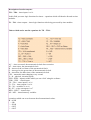
operations which can occur between the aforementioned values:
& = AND
| = OR
^ = XOR
~ = NOT
! = NOT
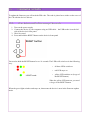
Example of equations which you can enter on the timer input:
Example
On the input of timer TI1 you entered ((INP3 | INP4)) & AC.
This means that for the timer to become active, the AC function must be active as well as either
input INP3 or INP4. This can be used if you want the effects of activating one of these inputs to be
valid at a certain time of day.
The equation entered on the timer input is then passed to the time modules
There are three time modules available for each timer.
•
Time to ON – is the time from when the voltage reaches the input (NO) or is cut off from
the input (NC) to when the input reacts. This option can be used if you want to delay the
reaction time. For example, if the voltage reaches the input, but the disappears again before
the given period of time passes, the input will not be triggered, the timer will be reset and
the input will again wait for the voltage. Only when the voltage is given for a period of
time longer than the one entered, the input will be triggered.
•
Time to OFF – this module works opposite to the first one. For example, in NO, if the
voltage disappears for some period of time, shorter than the one you set, the input will not
be triggered.
•
Pulse time – this is the time that will pass from the moment the timer activating signal
appears to the moment the timer is deactivated. For example, if you enter the value of 20
seconds, the time will deactivate automatically after 20 seconds. If the command which
triggers the signal appears again during those 20 seconds, the countdown will start again. If
the signal disappears before the given time has passed, the timer will be deactivated.
Example:
Let's say you have a backup power-generator in case of power outages and you want to
control the time that has to pass until the generator is started or switched off. If you set each timer
to 10 seconds then this will mean that the voltage will have to be gone for more than 10 seconds
for the device to start the generator and also that it will have to be back for more than 10 seconds
for the device to switch the generator off. The input will be immune to short power outages.
10.1.3.
The fourth tab – X variables and output relays
In the fourth tab you set logical functions for X variables and output relays R
Available functions and the operations between them are the same as for the timers in the second
and third tab.
You enter the equations in the assigned fields:
The equations for X variables – the conditions, which must occur for the X variable to be
activated, must be entered in these fields. Each variable has it’s own field.
Equations for output relays R – the conditions, which must occur for the given relay to switch on,
must be entered in these fields. Each variable has it’s own field.
In this example, the R1 relay will switch on when timer T1 is activated or virtual input VIR3 is
turned on.
10.1.4.
The fifth tab – input operation using the astronomical clock
and timers
In the fifth tab you have options which allow you to configure the behavior of chosen inputs
(only if they are operating in bistable, bistable + click, monostable + click, likely bistable or likely
monostable mode) in combination with astronomical clock and timers.
This option is very useful eg. when you want to switch off all unnecessary lighting at dawn or
switch the necessary lighting on at dusk.
The functions used in this tab are:
ASTRO – A
ASTRO CORRECTED – AC
RED – R
GREEN – G
BLUE – B
Options with the upward arrow switch on inactive inputs when the chosen function
becomes active AC, AT, R, G or B
For instance, if you chose option R/ (with the upward arrow) for input 1, the input will
become active (if it was not active) in the moment when the RED function, set up in the ASTRO
Timer (in this case it is the red timer) configuration menu, switches on.
The R\ (with the downward arrow) option will switch off an active input in the moment that the
chosen function becomes inactive (configuration description in the Astro Timer section).
For instance, if you choose option R\ for input 1, the input will switch off in the moment
when the RED function, set up in the ASTRO Timer configuration menu, switches off.
If you choose the not option, it will reverse how the function works. With the not option chose that
function will switch off an active input in the moment the chosen function becomes active. In our
case, if input 1 was active, it would have been switched off in the moment that the RED function
became active.
Using the adjusted Astro Timer ASTRO CORRECTED you then “move” the time of
dawn and dusk by +/- two hours. This means that if the sun rises at 6 in the morning, but you want
the input reset to occur a half an hour later then you can set the +30 minutes sunrise correction in
the ASTRO TIMER. To do this you need to enter the ASTRO Timer configuration window. The
configuration manner is described in the part of the manual related to the ASTRO Timer.
How can this function be useful?
For instance, if you want to switch off all lights connected to the inputs at sunrise and switch them
at sunset.
This is control using events.
If it is to be successful, the inputs which you want to control this way must be either in bistable or
CLICK bistable mode. If you use external bistable relays controlled by impulses then the inputs
must be set to CLICK monostable and an additional wire detecting the voltage from the bistable
relay must be connected to the physical input. You should analyze examples of stair lighting wiring
diagrams. PLC works as the last of the two-way switches and only executes a single switch on/off
operation and then does nothing while the user can use the circuit in the normal way. The PLC will
simply switch off the light instead of the user if it was on and vice versa. This will occur once per
event in such a way as if an invisible watchman switched the lights off for us at sunrise.
10.1.5.
The sixth tab – input and relay behavior after reset
After hardware or software RESET
– ignore “Time to ON” value for timer T1-T16
If the chosen timer has a set Time to ON then choosing this option will cause that after a
reset that time will be ignored, will not be taken into account. The setting will itself not be resent
but will simply once be ignored. This is to avoid long waiting periods after resets if those times are
set to a couple of minutes. It will accelerate the start of the device.
For example, you want one of the timers to be activated with the AC signal with a two
minute delay. This delay is not needed in case of a reset. Without applying the discussed option,
after every reset there would be a two minute delay before the timer started working. Applying this
option will cause the timer to switch on directly after a reset if the AC signal is still active.
- set clickable input variable INP/virtual variable VIR/relay variable REL
Activating this option will make the chosen input, virtual input or REL variable switch on
automatically after a device reset, disregarding it’s status before the reset. This function is useful
when you want some operations to be done automatically after a reset, without having to wait for a
signal to trigger them.
10.1.6.
The seventh tab – counters
Counters
Set/Clear selected counters
You can assign a set value to every counter. This will be the value from which the counter will start
counting up. At the moment there is no such thing as clearing a counter per se. If you want to clear
the counter you should enter 0 or any other desired value and check the checkbox on the right to
approve. Next press the big Set/Clear selected counters button.
Global sensitivity of bistable inputs
This setting declares the shortest length of an impulse that will cause a reaction of the input.
10.1.7.
The eighth tab – cooperation with other PLC2011 devices
Data export to shared memory
This tab is used for settings which allow you to control other PLC2011 devices or allow the
configured device to be controlled by commands from other PLC2011 devices.
To be exact, you can send out data from your device to use it to create equations in other devices or
get data from other devices and use it to create equations in your device.
For this you use the A1 I/O – CFG tab.
PLC2011 devices can cooperate with each other, send out and receive data from other devices. For
this they used the ‘shared memory’.
A couple of conditions must be met for this function to be working.
First, the cooperating devices must have the exactly the same password and salt set in the main
configuration (read more in the section about the password and salt).
Second, the devices must have the same transmission channel.
The transmission channel for the device is set in the Channel field. It is a value between 0 and
255.
Third, the devices must be in the same local area network.
Depending on whether you want the device to send out or receive commands you need to
set the options:
Enable shared memory input
Enable shared memory output
If you want the device to do both those things, you need to select both of these options.
The command which you can use are the same as those presented in the third tab. You
cannot however send out a combination of commands or an equation. Equations will be created in
the receiving device using data from your device.
Entered commands will be signals from your device that will trigger a reaction in other
devices. For example, if you enter INP1 into the table then the signal for other devices will be sent
out when you switch on this input in the transmitting device. Also, the signal will be sent out when
the input is switched off. The command will then stop being active.
Sending out commands
First, you need to set the Start Address Offset. This is the place in the shared memory
where you will start entering commands which you want to send to other devices.
The command table has 32 spaces (cells). This is the maximal number of commands that
can be transmitted between devices on one channel. Therefor you need to pick a values between 1
and 32.
The table is the same for all cooperating devices, but at any given moment you can only see
the commands coming from the device you are currently logged on to.
From your device you cannot see what variables on what addresses are sent out from other
devices.
This is why you should be careful when entering commands from multiple devices. You
should not enter more than one command in a single cell. This may cause unpredictable changes in
how the device works.
We advise you to print out or draw a similar table and use it as a ‘cheat sheet’ where you
can check what command from which device is in which cell.
The Start Address Offset field is supposed to help you keep the command in the shared
memory in order.
For example:
you begin to enter commands in the first device starting with address no.1
enter a string of command remembering to separate them with a signle space
click SAVE in the lower right corner
the commands will automatically be sorted and separated by comas
the number of commands will be counted automatically
the commands will be entered in the designated cells
you must remember to switch on command transmitting and, if needed, also command
reception
In the next device you need to set the Start Address Offset to 4 because the first three addresses
are already taken and the command table will be filled from this device starting with cell no.4.
You act in a similar fashion in other devices.
How to use shared memory data
If you have a command table ready you can start to use shared memory data in
equations.
How to enter this data in equations?
In the device receiving the commands you must enter it as a value from the command table,
from M1 to M32.
The number depends on the cell the command was assigned to in the transmitting device.
The M1 field starts the first column of the first row. The following fields are numbered in
an ascending way from left to right. The second row starts with cell M9, the third with M17 and
the fourth with M25. The last cell is M32.
For instance, you want to use virtual input VIR1 from one of the devices in your network
and you know it is written into cell M29. This is the value you need to enter into your equations.
What are you going to use these commands for depends solely on your creativity. The
commands from the shared memory can be bound together in more complex equations or used
with data from the receiving device
An advantage of the solution used in the device is that the commands are sent out to
each cooperating device at the same time.
Thanks to this you avoid situations where devices receive and react to a command with
delay caused by the fact that the commands were sent out to each device separately. This enables
you to carry out synchronized operations in many devices at the same time.
10.2.
OUTPUTS
The device has 7 relay outputs and every relay has a normally open (NO) and a
normally closed (NC) connector.
To make sure that the battery lasts as long as it can in case of a power outage you need to
configure the device in a way that minimizes the amount of relays working in the normally open
state throughout the day. This is why every relays has NO and NC connectors.
For instance, if you connect a device that works all day with only a short break during the
day, it is better to use NC connectors and only use the relay to break the circuit during it's break
rather than keep the relay on for most of the day. When calculating how long will the battery last,
have in mind that every relays uses ca. 0.45W.
In contrast to the A0 device, there is no separate output configuration window. Output
configuration is done in the X...R tab. Output programming is also different. You do not have to set
values such as Time to ON as they can now be contained in the timer variables and there is no
need to double them. Also, the ability to ‘click’ the relay using the computer software is gone.
However you can achieve a similar result if you assign the output to one of the virtual relays
REL1...7.
The function which you want to send to a given input may be configured freely. You can
assign a signal or a combination of signal to the output. An example of configuration is shown in
the X...R tab under the fields where you enter equations for outputs. Available signals and
commands binding them with each other are shown in tab T13...T16.
11.MODBUS
11.MODBUS
The Modbus protocol was implemented in PLC2011A1 to make the resources of the
device available for other devices or computers. In a cheap and easy way you can expand your
installation, based on PLC, with additional interfaces. You can also use PLC2011A1 as an Internet
interface controller for a bigger PLC using mobile and encrypted software.
For instance, if you have another manufacturer’s PLC device equipped with a RJ45 input,
you can share your resources with that device. You can control a different PLC device using an
Android mobile device via PLC2011A1. PLC2011A1 can also act as a shield for your network as it
has strong transmission encryption mechanisms with the AES-256 algorithm.
You can activate or deactivate an input or variable in your PLC2011A1 device using your
phone and immediately send this information to a different PLC device in your ethernet network
using the Modbus protocol. You can also connect your device’s open collector outputs to another
device’s inputs.
PLC2011A1 uses the Modbus protocol to send out a command to a desired IP address, TCP
or UDP port and MAC address.
PLC2011A1 uses TCP and UDP protocols for data transmission from the device to a
chosen internet or local network address and does not expect a response or confirmation.
PLC2011A1 ignores any commands sent it’s direction, ignore responses and does not react
to other Modbus inquiries from other Master devices. A computer, other PLC device, router or any
other device can be a recipient.
Due to a lot of errors in network protocol implementation in many older PLC devices,
which are not supported anymore, we decided on the following configuration.
PLC2011A1 send out TCP or UDP packets in the following way:
PLC2011A1 → different PLC
1. If “different PLC” is in your local network, the same subnetowork, the same network segment,
that means it has a similar IP address, e.g.:
PLC2011A1: 10.0.5.5
different PLC: 10.0.5.10
then you must establish what is that different PLC’s MAC address and enter it in the appropriate
field in the Modbus configuration window. The MAC address is a physical, device address of the
ethernet interface. There are may ways to find out a MAC address. It can be printed on a sticker on
a device, you can program your own address, use software dedicated for checking devices inside a
network, check in the router or by doing a couple of simple operations.
In Windows, run the CMD window (Start → Run → enter cmd)
In the cmd (command line) window enter:
c:\>ping 10.0.5.10 (there must be an answer – 3-4 packets if the “different PLC” is alive, you must
of course know it’s IP address)
Next enter:
c:\> arp -a
A table with IP and MAC addresses will be displayed. Write down the MAC address belonging to
the IP address in question.
In the PLC2011A1 Modbus configuration you should enter:
IP:10.0.5.10 – IP address of the different PLC to which you will send out packets
port: 502 – TCP or UDP port of the different PLC to which you will send out packets
MAC: 00:11:12:13:14:!0 – MAC addres of the different PLC to which you will send out packets
2. If the “different PLC” is ‘somewhere’ in the Internet, which means it has a completely different
IP address (it must be a public address), then you must establish it’s router’s LAN interface IP
address and the routers MAC address instead of looking for the “different PLC’s” IP and MAC
address.
Knowing the router’s IP address you can establish it’s MAC in the way shown before, first pinging
the router and then reading it’s arp table entering the “arp -a” line.
For example, you will receive this data which you must enter in the Modbus configuration field of
your PLC2011A1 device:
IP: 10.0.5.1 – this will be the router’s IP address
port: 502 – this will be the TCP or UDP port of the remote PLC – you do not change this
MAC: 00:A2:1A:3F:D4:18 – this will be the router’s MAC address
To resume, if the receiving device is in your local network, you send data directly to
the device. If it is somewhere in the internet, you sen data to it’s router.
Modbus packets sent from PLC2011A1 to a different PLC reach the space in it’s memory
entered in the Start address (16 bit) field, e.g. address no.300. Starting from this address, there
will be as many 16bit words taken as is the total from the options you selected using the check
boxes next to these options which interest you.
Every kind of data which is transmittable using PLC2011A1 has a defined length in 16 bit,
2 byte words and that many cells in the receiving PLC will be taken up, beginning from the start
address.
The data is connected, ‘glued’ together.
If you select three check boxes, like in the picture below, then first nine words will come from the
Astro Timer, the next four from timers T9...T16, and the last four from INP3...INP6, VIR1...VIR3.
They will be sent out in one packet in this order. The order goes from top of the list to the bottom.
Under the start address 300 of the receiving PLC you will find the first word of the Astro
Timer, then the first word of T9...T16 begins in 309 and INP3...INP6, VIR1...VIR3 in 313.
If you select another data segment which lies in between the currently selected one, then
the data below the selected check box will be moved down by as many cells as needed for the new
data segment. The data order in the receiving PLC will change.
You can use this data in the receiving PLC in any way you want, depending on your needs
and abilities.
Other fields also require some explanation.
Some older PLC’s with errors in Modbus implementation simply do not accept certain
values entered in the fields Transaction indentifier and lower.
There are controllers which do not accept certain values and there is no logical explanation
as to why this occurs. This concerns especially the Transaction indentifier value.
Remember that errors in entering the IP or MAC address will cause a total lack of
transmission. The device will not receive anything and will not signal that something is wrong.
These settings should be made carefully.
As the Modbus protocol is in no way secured from attacks at devices, encrypted or secured from
impersonating devices, you should take steps to ensure safety of the wiring and separate the
devices, which receive the transmission, from the internet with routers. Its good to configure a
VPN tunnel between boundary routers. This exceeds the contents of this manual and you should
consult a specialist on this matter.
Your PLC2011A1 sends out packets directly to the network interface of the destination PLC using
it’s MAC address without making ARP “who has” inquiry and without waiting for ARP “is at”
response.
This is why you need to establish the destination MAC address ‘manually’. This is an advantage as
an intruder trying to intercept IP addresses and corresponding MAC addresses will not be able to
‘hear’ the devices. This is because ARP packets are sent to every switch port and are ‘broadcast’
packets which makes possible to use them to create a device list and impersonate these devices.
Another reason to know the MAC address during configuration are examples of tested devices
which did not have properly operating network protocols.
We advise you to use the UDP protocol for transmission instead of TCP. The UDP protocol
generates highly lower network traffic between devices. Because the PLC2011A1 only sends out
data to another device, the retransmission ability of the TCP is not needed and even undesirable as
it generates unnecessary traffic and CPU usage. However, using the UDP protocol may not always
be possible as some devices may not adapted to it’s operation.
Using the Modbus protocol you can send out PLC2011A1 data from the AstroTimer, normal
timers, shared memory variables M, X variables, virtual relays REL, physical inputs INP and
virtual inputs VIR. All signals are assigned to a group which is sent out together. You cannot send
out a signal from a single input or variable. For instance, if you want to send out the signal for X3
you need to select the group X1...X8. Available signal groups are shown on the right of the
Modbus configuration window. To select a group of signal you need to check the check box next to
it.
What does each field mean?
•
Third party remote PLC IP or ROUTER IP – IP address of the device that is supposed
to receive the signal.
•
Third party remote PLC UDP PORT – port used by the Modbus protocol. By default
this is port 502.
•
Third party remote PLC MAC or ROUTER MAC – MAC address of the device that is
supposed to receive the signal
•
Transaction indentifier (16 bit) –
•
Protocol indentifier (16 bit) – this field is always 0 for Modbus messages
•
Unit indentifier (8 bit)
•
Modbus function code (8 bit)
•
Start address (16 bit) – the place where data saving in the receiving device will start
•
Transmit Interval 1...255s – how often will the device send out data to the receiver
•
UDP src port
•
Modbus mode – the type of used Modbus protocol. You can choose UDP, TCP or Modbus
OFF
12.
ASTRO TIMER
12.1.
What is the Astro timer for
The Astro timer is used to start and shut down various types of electric devices, e.g. lighting,
accordingly to the daily rhythm of sunrises and sunsets for the given geographic zone.
12.2.
•
•
•
How does the Astro timer work
The Astro timer operates based on the following information:
current date
the device's location (geographical coordinates of the place where the device was mounted)
time zone (time difference between the time zone where the device is used and universal
time)
This information must be entered during the device's primary configuration or in our device's at
any time via the computer network. Based on these information, the Astro timer switches on and
off appliances connected to the device, accordingly to astronomical sunrise and sunset.
What is universal time.
Universal time (UT, UTC, GMT) – the mean solar time on the Prime Meridian at
Greenwich Royal Observatory. It is the prime time zone. The time in other time zones is measured
in reference to this time zone.
Time zone – a region on Earth, more or less bounded by lines of longitude, that has a
uniform, legally mandated standard time, usually referred to as local time. The main 24 time zones
on Earth compute their local time as an offset from UTC. Local time in each time zone is UTC
plus current time zone offset for the location in question.
The Earth is divided into 24 time zones.
Examples of time zones and countries within them:
•
•
•
•
•
•
•
•
UTC +0:00 - United Kingdom, Ireland, Portugal
UTC +1:00 - Germany ( the local time in Germany differs by +1h from the universal time
meaning that when it is 12:00 AM in a country which uses UTC+0:00, like the United
Kingdom, in Germany the time is shifted forward by an hour to 13:00 or 1:00 PM) ,
Poland, Austria, Belgium, France, Denmark, Spain, The Netherlands, Norway, Switzerland,
Italy
UTC +2:00 - Finland, Greece, Turkey
UTC +3:00 - European Russia
UTC +8:00 - China (the whole country uses the same local time, despite its large area),
UTC +9:00 - Japan, North and South Korea
The United States are scattered across several time zones.
UTC -8:00 - West Coast, states such as California ( Los Angeles, San Francisco ) or
Washington ( Seattle )
UTC -5:00 - East Coast with cities such as New York or Washington D.C.
To enter Astro Timer settings click the Astro Timer button:
A new window will pop out:
12.3.
Where do you use the Astro timer
The Astro timer can be used in street lighting systems, shop-window lighting systems,
billboard lighting systems etc.
The way it works is similar to light sensors – it's task is to switch on or off the lighting on a street
or square depending on the time of day. It can turn on the lights when the sun is setting and turn
them off when the sun is rising and lighting is no longer required.
The main difference between the Astro timer and devices based on light sensors is that the
Astro timer can work whether or not it is getting information about the current state of illuminance
outdoors. It is also much more precise. It can work closed in a electrical cupboard and is
insensitive to factors such as high cloudiness, massive snowfall or rainfall etc. which can cause
temporary darkness. Also, light sensors can get dirty which can make them malfunction. The timer
calculates the time of sunrise and sunset each day and commands connected devices based on these
calculations.
In the device, you can 'correct' ( speed up or delay ) the time of sunrise and sunset.
What does this mean?
Look at the example below.
•
•
•
Sunset is at 4:48 P.M.
Traffic on the street where you have your shop or your billboard starts growing at 3 P.M
Approximately half-an-hour before sunset it starts getting dark and your shop-window,
your billboard (or any other thing you want to expose) is not as visible as you would like
•
•
•
→ correct the sunset time by 30 minutes (4:18 P.M.)
→ your device will switch on the lighting 30 minutes before sunset
→ the corrected time will of course be different every day, the actual sunset time will
always be corrected by 30 minutes
How do you do it?
•
Assume that:
today is Tuesday – the current day of the week is always highlighted in red
For the device to work on a given days schedule you need to check
the 'Activated' check-box (single click). Otherwise the commands for
this day will not be executed.
Sunrise and sunset times are calculated by the device for the
given day are marked on the first horizontal axis under the
timer – yellow is the period of time between sunrise and sunset, the day and black is the
night
•
•
•
•
•
•
•
•
in this example, the sun sets at at 16:09 or 4:09 P.M.
You want the lighting to turn on half-an-hour earlier, so you must correct the sunset time by
-30 minutes
You correct the sunset time in the 'Sunset correction' box
You set this value individually for every day
You either enter the desired values yourself or use the arrows
The available range is from -128 minutes to +127 minutes
In the picture, the box where the sunset time on the current day (Tuesday) was corrected by
-30 minutes is marked in blue
•
settings of the timer after the correction are visible on the second horizontal axis under the
timer
•
•
You see that the sunset time was moved back 30 minutes and is now at 16:18 or 4:18 P.M.
If you correct the time using arrows you will see on the corresponding axis how the time
changes on-the-fly
The effect of this operation will be that your lighting will switch on half-an-hour before
sunset
•
12.4.
TIMER function – Night Breaks ( Night Intervals )
The device also has a programmable timer that cooperates with the Astro timer. Using this
timer you can set for every day of the week three periods of time when the Astro timer will stop
working. This function is sometimes called a 'Night Break' as you usually use it during the night
when despite the fact that it is dark outside you turn off the lighting to save energy. You can also
use during the day when you want to turn the lighting on for a period of time even after sunrise.
How does this work?
•
•
•
•
•
Let's go back to our previous example
You turned your lighting on at 16:18 or 4:18 P.M. So 30 minutes before sunset.
Traffic on the street where your shop-window or billboard is placed is high until late
evening hours and stops almost completely at 23:00 or 11:00 P.M.
The following day the traffic starts at 5:00 (A.M.)
Between 23:00 (11:00 P.M) and 5:00 (A.M.) almost no one passes by your shop-window or
billboard so there is no point in lighting it due to the costs.
You want to turn off the lighting for those 6 hours during the night
How do you do it?
•
In the middle part of the 'Astro timer' window there is a timer – on the picture below this
timer is inside the green frame
•
•
For each day you can set three periods of time where the way the Astro timer works will be
modified
Each of these periods has two fields:
➔ 'Start time'
➔ 'Stop time'
•
In the first of the fields enter the time you want the break to start, in the second the time
you want it to end
•
•
In this example the devices task is to turn on the
lighting after sunset, so reversing that function
will turn the lighting off
Go to the current day in the timer window
First pick the time you want the 'break' to start
In the 'Start time' box, set 23:00 (11:00 P.M.)
using the arrows or typing it in
• In the 'Stop time' you should enter 5:00 (A.M.)
but since the break starts one day and ends the
next day you need to 'divide' the break into two
parts
• The first part of the break should be 23:00-00:00
(11-12 P.M.) of the current day (Friday)
• The second is 00:00-05:00 (12 P.M. - 5 A.M.) the
next day (Saturday)
• The device will smoothly switch from Tuesday to
Wednesday merging the two parts into one
Remember to check the 'Activated' check-box for both Tuesday and Wednesday!
•
•
•
The results of the settings done so far are:
1.
2.
3.
4.
5.
6.
7.
The lighting switches on half-an-hour before sunset
It is on until 23:00 (11 P.M.)
At 23:00 (11 P.M.) switches off automatically
The lighting stays off until 5:00 (A.M.) the next day
At 5:00 (A.M.) the lighting switches on again.
It stays on until sunrise.
At sunrise the lighting switches off
You can of course apply these settings for the whole week:
Remember to check the 'Activated' check-box for every day of the week.
BREAKS – some additional information
•
•
•
•
•
•
for every day you can set up a maximum of 3 breaks
the breaks do not have to be entered in a chronological order – the software will sort them
by itself
the settings are visible on the diagram below the timer bar.
the red and green parts are the breaks you set (if you set a third break it will be visible in
blue)
the settings on the diagram are for the current day, below you see that the day starts with a
break until 5:00 (A.M.) and ends with a break starting at 22:00 (10 P.M.)
the diagram for Tuesday ends at midnight and if you want to see Wednesday's diagram you
need to click on the word 'Wednesday' above the main part of the timer. You will then see
the second part of the break you planned for Tuesday/Wednesday night.
The last axis shows the result of merging the settings of the Timer and the Astro timer
after correction.
The result depends on what logical operator you use to connect the corrected Astro timer
settings with the timer settings.
Astro timer
•
•
logical value 0 – yellow field on the axis
logical value 1 – black field on the axis
Timer
•
•
logical value 1 – when on (red, green or blue field)
logical value 0 – when off (no bar, empty field visible)
Logical operators:
•
OR (can be called as 'alternative') – logical value 1 will be achieved if either the timers or
the Astro timer logical value is 1 or both of their's logical value is 1 at the same time.
How the OR logical operator works
Astro timer
Timer
Result
0
0
0
0
1
1
1
0
1
1
1
1
Example:
•
XOR – logical value 1 will be achieved if the logical values on the timer and the Astro
timer are different from each other
How the XOR logical operator works
Astro timer
Timer
Wynik
0
0
0
0
1
1
1
0
1
1
1
0
Example:
Comparison
On the picture above:
– ASTRO CORRECTED – name of the variable used in the input's logic functions
– ASTRO – name of the variable used in the input's logic functions (the result of logic
operations between ASTRO CORRECTED and the Timer)
The OR function will change it's logical value from 0 to 1 but not the other way around.
The XOR function will change it's logical value as the timers value is always 1
Logical functions do not occur during breaks between the timer's periods of work. The
corrected Astro timer is not processed and is simply copied to the lower axis.
If the color on the lowest axis is yellow it means that during that period of time the value of
the logical operator is 0.
If the color on the lowest axis is black it means that during that period of time the value of
the logical operator is 1.
Only the values seen on the lowest axis, obtained as a result of a logical function
between the timer and the Astro timer are passed on to be used by the relay if the 'ASTRO'
function is on.
If you use the 'ASTRO CORRECTED' function, the values further processed by the
relay are the values on the second axis as that is where the relay takes data for processing
from.
A new option was added in the newest versions
You can also set the relay to process the values from the third axis which represent the
hours of the so called 'night breaks'.
Descriptions
– R – red bar ( RED )
– G – green bar ( GREEN )
– B – blue bar ( BLUE )
These bars are the so called 'night breaks', the first one of which is red on the diagram, the
second one is green and the third is blue, which is why they are described as R, G and B.
The values may be connected with each other and also with other logic functions available for the
chosen input.
The functions work similarly to functions “ASTRO” and “ASTRO CORRECTED”. The red, green
or blue bar depicts logical value “1”. A white field instead of a bar means that the logical value is
“0”.
This means that e.g. the “R” function will be active in the period of time shown on the third
diagram as a red bar. The “G” and “B” functions will act analogically, taking into account their
own bars.
13.
WWW SERVER
The device has a built-in WWW server that you can access using a web browser from your
computer or cell phone. It is a simple website designed specially for cell phones. It allows you to
check the current status of the devices inputs and outputs. You cannot however switch anything.
Configuration
1.
2.
3.
4.
Run the software
If you have several devices, pick the one you want to connect to from the list on the left
Enter the password
When you are connected, press the Main Configuration button in the main window
5. The opened window will allow you to configure the computer network
The WWW Server will be visible in the local network under the IP address that was given
to the device when the network was configured
For example, on the picture below the IP address is: 10.0.5.3
6. Additionally, you must pick the TCP port on which the device's WWW server listens. Enter
the number of the port in the field marked red on the picture below. Our example looks like
this:
TCP port for WWW: 81
The standard number for this port is 80.
If you have a couple of devices in the local network then each should have a different
WWW port number
What should you enter in your web browser? (local network related)
•
•
•
if the port number is the standard 80 then type in only the IP address of your device (you do
not need to add the port number) – in this example “http://10.0.5.3 “
if you changed the port number to a value different than 80 then you need to add a colon
and the port number after the IP address – in this example “http://10.0.5.3:81"
if you change the port number to 0, the WWW server will be deactivated
The WWW port number can be any value between 1 and 65535.
Remember to save your settings after changing them using the SAVE button.
7. After saving your settings, return to the program's main window and press the
"Texts/WWW" button.
8. The Website editor window will pop out.
What is this window for?
Title of the website - in this field you should enter the name you want your device to have
in the web browser. The name can have up to 32 ASCII characters (UTF-8 encoding). Some
special characters (typical for a specific alphabet) can take more than one letter spot so the text
entered will have to be shorter.
In this example the title will be My Home
On the left listed are inputs and relays in the device. You can name every one of them by
entering the desired name in to the text-box next to the input/relay of your choosing. For example,
you can name the after the appliance that they control – garage gate, lighting, roller shutters, etc.
This will allow you to check whether your gate is open, your lights are on or shutters are pulled
down when you are away from home. You can check this using a web browser on a computer or a
cell phone. What device you connect to the relay is up to your needs and invention.
These names will also be visible in the software's main window as descriptions of
individual inputs or relays. The description is shown when you put the mouse cursor on the
input/relay buttons. This is done so that you do not have to guess which device is where if you do
not remember.
The website refreshes automatically with a frequency that you set. Changes made in the
names of inputs and relays are visible after the next refresh. You can also refresh the website
manually (F5) and then the changes are visible immediately.
This is an example of how the website looks in a computer web browser:
This is how the website looks in a cell phone web browser:
9. Server visibility outside of the Local Network Area
The server can be visible from outside the LAN but you need to configure the router and
redirect the packets accordingly. Router configuration is not a part of this manual but you can be
sure that you make the appropriate settings in any ADSL or cable router.
10. If the device was given a public IP address then it will be visible on the Internet just as any
other computer.
14.
HOW TO USE THE DEVICE – IN SHORT
The basic version of the software used to control the device using a PC is delivered together with
the device.
The software does not require installation.
Simply copy the software file to any location on your computer and run it.
Do not run it from CD!
14.1.
Starting the software
This window will pop out
Next you should:
– turn on the relay and connect it with the computer using an USB cable
– do the 'First Run' operation. It is described thoroughly on page 13.
– when you achieve connection with the device, it's ready to use
14.2.
Main window
This is how the software looks any time you run it.
At the bottom, in the Password field you need to enter the password that you have set during the
First Run procedure and the press Accept.
When you quickly double-click the field where you enter the password, a virtual keyboard, which
you can use to enter the password, will appear.
You need to enter the password every time you run the software.
Without entering the password it is impossible to connect to the device through the internet.
After you enter the correct password for the chosen relay, the triangle indicator will turn yellow.
This means that connection has been achieved.
14.3.
Main window description
On the left there is a list of the devices added so far.
The triangle showed on the picture below indicates whether you are connected to the currently
chosen device. Successful connection will result in the triangle changing color to yellow. When
there is no connection the triangle will be gray.
The red box on the picture below shows indicator depicting the current status of the device’s
physical relays – R. Green means the relay is active, gray means it is inactive.
Lower are indicators showing the current status of virtual relays – REL. Blue means the relay is
active, gray means it is inactive.
The indicators in the red frame on the picture below show the status of X variables. Active
variables are shown in pink, inactive ones are shown in gray.
The indicators beneath the display show whether electric current is flowing through the given
physical input. If the current is flowing, the indicator will be orange. If not, it will be gray.
Placed lower are INP control which allow you to ‘click’ the chosen input using the software.
The inputs will react only if the 147 safety code is currently entered. An active input will be
displayed in yellow. A gray icon means that the input is inactive.
On the right there are virtual input VIR controls. The virtual inputs will react only if the 147 safety
code is currently entered. An active virtual input will be displayed in yellow. A gray icon means
that the virtual input is inactive.
Below are BT- and BT+ indicators. These are ‘lit’ if a battery is connected to the device.
In the middle of the main window there is a display showing various parameters of the device. The
display has five different screens. An individual description of each screen is in a further part of the
manual.
Left of the display there are button which open the Main Configuration, WWW configuration
and MODBUS configuration windows. Below there is also the Astro Timer configuration window
button.
Right of the display there is the round RESET button. Clicking it is only possible with the 147
safety code entered and it will cause the device to restart.
Shown in the red frame is the field where you enter the 147 safety code and the button which resets
the code.
Above you can chose with what frequency do you want the software to communicate with the
device.
On the right of the main window there are the T timer indicators. Active timers are shown in red,
inactive in gray.
On the bottom of the main window there is the field where you enter the password to the device.
You need to confirm the password with the Accept button.
14.4.
USB CONSOLE tab
This tab is for:
– configuring the device and setting up the password
– updating firmware (last section of this manual)
– synchronizing time
All these procedures require the device to be connected to the
computer with an USB cable!!!
14.5.
14.5.1.
SETTINGS tab
Cryptographic salt for secret passwords
Salt configurations are described in the Password and Salt section.
14.5.2.
Encryption tools
After pressing the Encryption tools button a new window will pop out.
This window can be used to encrypt text. To do this, you first need to enter a password in the field
where you normally enter the password to your device. This password will then be used to decrypt
the text. The entered password does not have to be the password to one of your devices.
For example, let's say that the password is the first 15 letters of the alphabet. Enter and accept them
and re-enter the Encryption tools window. In the main text field enter a short text, e.g. 'Alice has a
cat' and then press the Encrypt button.
The text will be substituted with a character string.
Now, if you press the Decrypt button, the character string will change back into the previous text.
The character string will be different each time even if the password stays the same.
If the password is changed between encryption and decryption, the decryption will not be
successful. Instead of the original text, you will get back a different character string.
Only after you enter the password that was in use during the encryption, will you get the original
text. In this example, the text will be decrypted after you re-enter the first 15 letter of the alphabet.
The Cut button clears the contents of the screen and copies it to storage. You can then paste it
anywhere else, like an SMS, a text document or an e-mail using the paste function.
The Paste button enters the content of the storage to the software encryption window.
The Erase button permanently erases the contents of the window, together with the text, and clears
the place in the computers memory where the password was stored.
Using the ENCRYPTION TOOLS function you can send someone a secret, encrypted
message.
The recipient will only need the relay PC or Android software, even if he himself does not
own a device, and the password to read the message. If someone unauthorized intercepts the
message then without the software and the password, the message will be useless to him. The
message can be read only by a person who knows the password.
Keep in mind that the SALT TXT settings will impact the ability to decrypt someone’s
message. This function is designed for a group of people in a house or company who want to keep
their conversations confidential to telecommunication operators and use the same password and
salt
For safety reasons you should not use passwords which you use elsewhere, e.g. in your email account. The password must have at least 15 characters. When entering the password
remember that the software differentiates capital and small letters. The letter 'A' will be treated
different than the letter 'a' and the software will act in the same way with other characters. Before
entering the password remember to check whether the Caps Lock button is pressed as this can be a
frequent reason as to why the password could be read as wrong.
You should also check SALT TXT settings (analogically as when setting SALT for PLC)
Salt is a non-confidential text and you do not need to hide it. It is an additional obstacle in the
process of trying to break the password using mathematical methods.
VERBOSE LOGGING TO THE CONSOLE
READ LOGS TO THE CONSOLE
The functions concern the PLC2011B0 Programmable Alarm Unit
14.5.3.
SAVE/RESTORE configuration
The current configuration of:
– inputs
– outputs
– astro timer
– www server
can be saved to a file (*.ccr) by pressing the Save to file button.
To restore the settings or apply the in another device, after picking it from the list in the left part of
the window and connecting to it, you need to press the Restore from file button, find the
configuration file and press Open.
The device will load the configuration file and restart.
In the STATUS field the information “RESET” will be shown.
This does not concern the main configuration as the network settings etc.
14.5.4.
LANGUAGE selection
You can choose the language from a list.
After setting AUTO the language automatically switches to the language of your Windows.
Language settings are saved automatically after every change.
14.5.5.
NTP settings
To use the following settings you need to log on as the
administrator on computers with Windows7 !!!
Local NTP server on this computer
This is a tool that allows you to configure your computer to be the NTP server. This menu does not
require being connected to the device as it's used to configure only your computer.
NTP client – this service downloads the current time from the internet. It should always be on.
NTP server – this service will allow other computers or relays to download the time from your
computer. It will 'serve' time to relays.
NTP Client – pooling interval – how often (in seconds) will your computer download time from
the internet as an NTP client. If you want the time in your computer to be correct you should enter
3600 – update every hour.
Windows Firewall settings on this computer
You need to configure your Windows Firewall to let through requests going to the NTP server if
you want your computer to work as one. You need to allow UDP packets with port number 123 to
go from the LAN to your NTP server service.
In Windows Vista and Windows 7 you need to run the software
when logged in as the administrator.
14.6.
DEVICE A1 tab
This tab is used to control the device, configure the inputs and outputs, astro timer and www
server.
You can see the status of the inputs and outputs as well as the X variables and T timers of the relay
that you are connected to.
You can change the relay and output status after you enter the 147 safety PIN code in the field in
the right of the window. When you enter the code, the display in the middle of the screen will
change it's color to pink. After you are finished making changes, we advise you to switch back to
safe mode so that you do press and change anything by accident. To do this press the Reset button
next to the field where you entered the code. The display will go gray again and you will be able to
make changes only after you enter the code again.
14.6.1.
Display ( radio buttons 1 to 5 )
Screen #1
– name of the chosen device
– it's IP address
– UDP port number
– firmware version
Screen #2
– counter status of the chosen device
Screen #3
– ping between the device and the computer
– sunrise and sunset times
– the next parameters are only service parameters, without meaning
– shown last is the current voltage on the battery
Screen #4
– time according to the NTP server and the device's internal clock and the difference between
them
Screen #5
- tbd
14.7.
Adding a new device
To add a new device (relay) to your list right-click in the field where the list is placed on the left
side of the window.
Pick Add a new device
The Add a new device window will pop out. Here enter the name under which you want the
device to be displayed on the list, the device's IP address, UDP port number, device type and the
time zone where the device is placed. If the device's timezone is the same as the computer's
timezone then pick AUTO.
You save by pressing the Accept button.
The added device will be displayed on the list on the left of the window.
To connect to it you need to choose it, enter the password and the accept it.
14.8.
Resetting the device using the software
To reset the device you need to press the round button next to the display ( 147 code first ). The
cursor will change to hand when you put it over the button. The button changes to red when
pressed.
Resetting the device will clear the current status but will not change the programmed logic.
This is how the window looks after a reset.
14.9.
Operation in tray
Double-clicking the display will cause the program to collapse to an icon on the toolbar next to the
clock.
Status change of any of the inputs while the program is operating in tray will cause a message to be
displayed:
The information contains the name and IP address of the device where the status change occurred.
15.
FIRMWARE UPDATE
To update the firmware you will need the PIN code. The code is placed on a sticker on the cover of
the CD with the device's drivers.
15.1.
How to turn on the firmware update mode
1. Turn on the power supply
2. Connect the device to your computer using an USB cable - the USB socket is on the left
side of the device's front panel
3. Wait 10 second
4. Press and hold the RESET button on the device's front panel
You need to hold the RESET button for ca. 10 seconds. The LEDs will switch on in the following
way:
– all three LEDs switch on
– red LED stays on
– yellow LED switches on (let go of
the RESET button)
When the yellow LED turns on, you need
to let go of the RESET button.
When the green light switches and stays on, that means the device is now in the firmware update
mode.
15.2.
Firmware update
When the device is in the firmware update mode, you need to:
1. Open the software on your computer
2. Go to the USB Console tab
3. In the USB configuration field pick the Firmware update option button
4. The lower buttons and the box where the PIN code should be entered will become
highlighted.
5. Enter the PIN code into the PIN for USB functions box
6. Do not press the 'ENTER' button on your keyboard, it's enough if you just type it in
7. Next, press the Open firmware button and find the firmware update file
8. The file has a '*.bin' extension. If you received a '*.rar' or '*.zip' file, you must extract it
first
9. Select and open the firmware update file
10. The firmware update file will be loaded
11. The file's path and size will be displayed in the console window
12. Next, you need to write the loaded file
13. Press the Write firmware button marked red on the picture below
14. When you press the Write firmware button, the update will start. You can view it's
progress on a bar in the lower right corner. During update, the progress bar changes color
from gray to red. The progress is measured in '%'.
15. When the update is finished, the progress bar will change color to green.
16. The console will display information about the update being finished and the version of the
new firmware
17. After you update the firmware, you need to reset the device
18. Press the RESET button on the front panel
19. All three LEDs will switch on, then the red one will stay on for a short time
20. The device is ready for normal operation
15.3.
Errors during firmware update
If an error message, similar to the one on the picture below, is displayed after you press the
Write firmware button, it means that:
1. You did not enter the device into firmware update mode or
2. You did not enter the PIN code correctly
Repeat both of these operations.
16.
ADDITIONAL INFORMATION
In this file you can find examples and diagram of connections that can help you build your own
intelligent house instalation
The manual is updated systematically so please check it on a regular basis.